Abstract
Vibration of manufacturing machine parts can be reduced by applying CFRP to precision machines. Recently, the use of 3D printers in manufacturing has increased. However, there are few studies on the vibration characteristics of 3D printed composite materials. The objective of this study is to analyze the vibration reduction effect of a 3D printed composite material used as a CFRP chuck adapter. The existing chuck adapter is made of steel. In this study, the vibration values for three types of CFRP, steel, and CFRP with steel chuck adapters are compared. The products were rotated at 10, 500, and 1000 rpm, and the vibration velocity and displacement were calculated as an average value after repeating each measurement 5 times. Vibration velocity was improved by up to 64% and displacement by up to 31.1%. These results can be usefully applied to other mechanical parts requiring vibration damping.
1. Introduction
With recent industrial advances, research on the development of materials that can simultaneously satisfy the light weight and stability requirements of materials, including composite materials, is being actively conducted. Carbon fiber reinforced composite plastics (CFRP) have been extensively used in many applications, such as aerospace, mechanical, and civil structures, because of their high strength-to-weight and stiffness-to-weight ratios. CFRP materials are made using an epoxy resin with excellent mechanical and chemical properties, combined with carbon fibers as a raw material. The stiffness and strength of each fiber can be controlled in a complex manner, and CFRP can be produced using fibers with different moduli of elasticity [1,2].
The vibration reduction of a chuck adapter has important application value in reducing the vibration of machine tools. The vibration characteristics of the mechanical parts have been studied. Zhang et al. [3] studied a method for reducing motor vibration. It was found that the CFRP motor housing had a reduced vibration amplitude compared with the conventional motor frame. Druesne et al. [4] studied modal characteristics applied to vibration variability for an electromagnetic motor. Mendon et al. [5] studied the dynamic characteristics of rotors installed on composite shafts. Marco et al. [6] studied experimental characterization of a high-damping viscoelastic material enclosed in carbon fiber reinforced polymer components. Enrico et al. [7] studied the influence of freeze-thaw aging on the impact performance of damped carbon fiber reinforced plastics for automotive applications.
Most chuck adapters are now made of AISI 1045 steel and other metals, but the damping capacity of metals is limited, with too much vibration. CFRP is a type of structural and functional material with high strength, high specific strength, high specific modulus and light weight. It also exhibits excellent damping performance and can be directly applied in structures for vibration reduction [8,9,10]. Adams and Bacon [11] studied dynamic Young’s modulus of CFRP and metals and the flexural damping capacity.
Recently, several studies have focused on the vibration characteristics of composite materials. Rueppel et al. [12] applied the logarithmic decay method, dynamic mechanical characteristics, and the vibration beam method to study the damping characteristics of a CFRP laminate. The results showed that the damping of the structure increased with the angle of the laminate when the frequency was below 300 Hz. Maheri [13] studied the effect of deposition and boundary conditions on the modal characteristic of composite panels. Abramovich et al. [14] studied the damping measurements of aluminum and laminated composite materials using the hysteresis loop method. Composite laminates have large damping loss factors. Martone et al. [15] and Assararet et al. [16] investigated the damping properties of composite plates and cantilever-beam structures. Zhang et al. [17] studied structure and modal analysis of a carbon fiber reinforced polymer raft frame. Hong et al. [18] studied vibration analysis of a composite blade. Wen et al. [19] studied the design and vibration damping of a truss-type CFRP raft frame. Billups and Cavalli [20] studied 2D damping predictions of fiber composite plates (layup effects).
CFRP is a material with three times the inelasticity of steel, and excellent vibration damping. Vibration in machine parts that require precision in operation can be reduced by applying CFRP during manufacturing. If a composite material is produced using a 3D printer, the shape can be free form and the fiber content and orientation can be adjusted so that the product can be manufactured fit for purpose. With the development of the 3D printing industry, interest in research on the vibration behavior of composite materials is also growing. However, few related studies have been conducted. Ekoi et al. [21] conducted a study on the fatigue and mechanical behavior of woven and nonwoven continuous CFRP composites manufactured using 3D printers. More studies on the vibration characteristics of CFRP are urgently needed to produce mechanical parts that are stable in terms of vibration and have excellent vibration reduction characteristics.
In this study, modal and vibration experiments were conducted on a CFRP chuck adapter. The results were compared with the vibration of a steel chuck adapter and a CFRP with steel chuck adapter. This has important applicable value for reducing the displacement and vibration of machine tools. This method is illustrated in Figure 1.
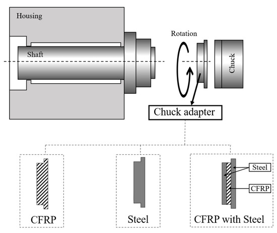
Figure 1.
Schematic illustration of vibration experiment for different chuck adapters (CFRP, steel, and CFRP with steel).
2. Materials and Method
2.1. 3D Printer
3D printing, also known as additive manufacturing, has gained increasing attention owing to its unique potential for creating geometrically complex structures, which enables mass production while having economic and environmental benefits. In this study, a chuck adapter was fabricated using a 3D printer (Mark Two, Markforged, MA, USA). Figure 2 shows the Markforged Mark Two 3D printer used in this study, and Table 1 lists the performance parameters of the printer.
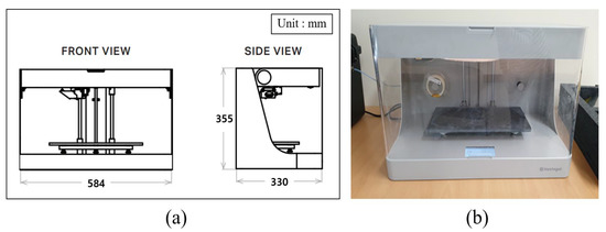
Figure 2.
3D printer. (a) drawing and details, (b) photograph.

Table 1.
Mark two 3D printer specifications.
2.2. Chuck Adapter
A chuck adapter is a device that is attached to the end of a machining tool to hold the workpiece. Three or four jaws are attached to hold the piece being machined. It is fixed to the main shaft and used to hold the workpiece steady while being machined. In this study, a steel chuck adapter was selected as a reference. The CFRP chuck adapter is designed to be identical to the steel chuck adapter. Figure 3 shows the steel chuck adapter, CFRP chuck adapter, and CFRP with the steel chuck adapter.
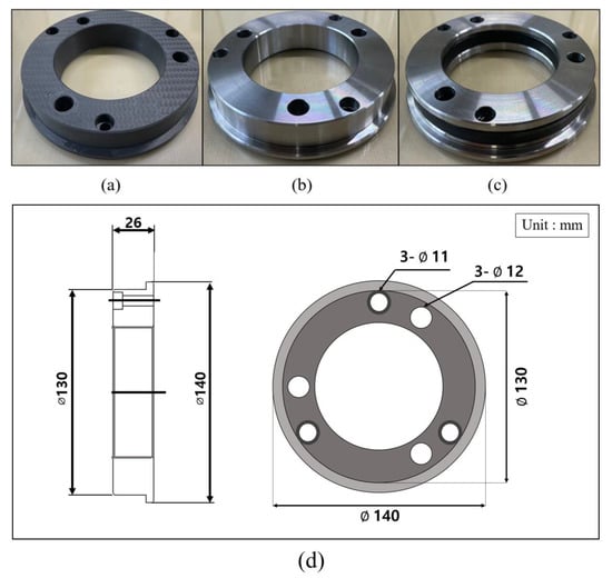
Figure 3.
Photographs and drawing of chuck adapter. (a) CFRP, (b) steel, (c) CFRP with steel, and (d) drawing.
The material used in the experiment is a structure in which Onyx material (a type of nylon filled with micro carbon fibers) and carbon fibers are laminated layer-by-layer. Onyx material is 1.4 times stronger and harder than ABS, and has excellent surface finish, chemical resistance, and heat resistance. Carbon fiber has the highest strength-to-weight ratio among the reinforcing fibers and is six times stronger than Onyx material. The chuck adapter was 140 mm in width, 130 mm in length, and 26 mm in height, and the Onyx and carbon fibers were laminated in layers 0.125 mm thick. Table 2 and Table 3 list the chemical composition and mechanical properties of the steel. Table 4 lists the physical properties of Carbon and Onyx.

Table 2.
Steel chemical composition (wt.%).

Table 3.
Steel mechanical properties.

Table 4.
Onyx and Carbon material composites.
2.3. Experimental Setup
A chuck adapter vibration experiment was conducted using a lathe machine (SE2200A, Hyundai WIA, Changwon, Republic of Korea). A chuck adapter was attached to the chuck, and the chuck was attached to the lathe for the vibration experiment. A controller was used to operate the lathe, and the experiment was conducted at 10, 500, and 1000 rpm. A system capable of monitoring the vibrations through a computer connected to data acquisition equipment was established. Figure 4 shows the equipment used for the chuck adapter vibration experiments.
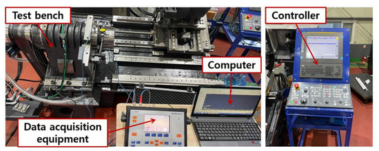
Figure 4.
Experimental arrangement for vibration experiment.
2.4. Measurement
The equipment used in this test (Figure 5) is a vibration measuring device (VL8000, Hofmann, Pfungstadt, Germany) with a resolution of 0.1–200 mm/s, a vibration half range of 0.05 mm/s, and an uncertainty of 0.0289 mm/s. The bandwidth of the measuring device was determined to be 10 Hz–10 kHz using the root mean square (RMS) method.
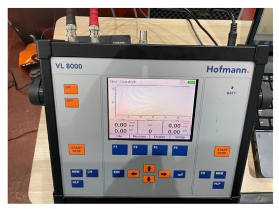
Figure 5.
Vibration measurement device.
During the test measurement, the vibration measurement position of the chuck adapter was one point for the bearing part and two points for the fastening part, and the values were compared by assigning the effective RMS value, peak value, and peak-to-peak value to the vibration velocity settings. The environmental conditions during the experiment were a temperature of 21.0 ± 1.0 °C and a relative humidity of 50 ± 5%. Measurements were repeated five times each. The measurement points are shown in Figure 6.
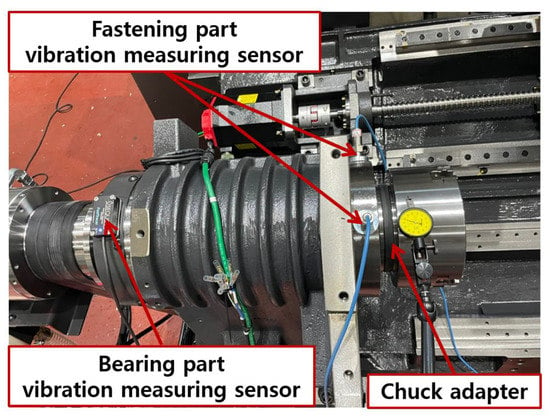
Figure 6.
Experimental setup for vibration experiment.
2.4.1. Natural Frequency Measurement Standard
Frequency is the number of times that repetitive motion occurs per unit of time when an object continuously repeats a constant reciprocating movement in a vibrating motion. This can be expressed using the following relationship:
where f is the frequency (Hz), T is the period (s), and ω is the angular velocity (rad/s).
The natural frequency is the unique frequency of an object. The vibration of the system, including the object, can be obtained using mass, springs, and dampers. For a one-degree-of-freedom vibration system with one mass and one spring, the theoretical natural frequency can be obtained using the following equation [22,23]:
where is the natural frequency (Hz), k is the spring constant (N/mm), and m is the mass (kg).
2.4.2. Vibration Measurement Standard
Vibration measurements were conducted according to the ISO 20816-1 [24] standard. Measures representing the magnitude of vibration include vibration displacement (μm, peak-peak), vibration velocity (mm/s, RMS), and vibration acceleration (m/, RMS), and this standard adopts RMS, which is the effective value of the measured vibration velocity.
The RMS value of the vibration velocity was calculated as the time record v(t) of the vibration velocity. This can be expressed as:
Spectral analysis shows that the magnitudes of the vibration acceleration, velocity, and displacement are (m/), (mm/s), and (μm, peak-peak), respectively, which represent the vibration frequencies (i) (j = 1, 2, …. n) and can be obtained as a function of the RMS velocity, as follows:
If the oscillations are given as only two major frequency components, then if the RMS values are and , then is approximately determined. This can be expressed as:
This can be expressed simply when any specific vibration component is excellent as:
where v is the peak amplitude of the vibration velocity (mm/s), s is the peak-peak amplitude of the vibration displacement (μm), and f is the dominant vibration frequency (Hz).
3. Results and Discussion
3.1. Natural Frequency of Chuck Adapter
A natural frequency experiment was conducted to present the experiment under natural frequency experimental conditions, and a durability experiment was conducted to show that the CFRP chuck adapter had a durability similar to that of a conventional mechanical part. The natural frequency and durability experiments were conducted before the vibration characteristics experiments to demonstrate that the three types of chuck adapters were manufactured consistently and to compare frequencies with conventional mechanical parts.
The natural frequency experiment of the chuck adapter was conducted on the J260/SA7M high-amplitude vibration tester (J260/SA7M, IMV, Osaka, Japan), as shown in Figure 7 and Table 5. One sensor was attached to the table for control and the other sensor was attached to the chuck adapter to check for resonance when measuring the resonance frequency. The frequency response data were transferred to a computer.
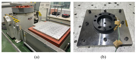
Figure 7.
Natural frequency and durability experiments for chuck adapter testing equipment. (a) High-amplitude vibration, and (b) natural frequency experiment.

Table 5.
Vibration tester specifications.
The vibration measurements were conducted according to the ISO 10811-1 [25] standard. Natural frequency data were obtained using the K2/L sine vibration control system software(IMV, Osaka, Japan). Natural frequency experiments were conducted at a frequency of 2 kHz, gravity acceleration of 4 g, time period of 518 s, and vibration of 172 kilocycles. The frequency response signals showed similar trends for each of the three types as shown in Figure 8. The resonance frequencies were concentrated in the range of 980–1000 Hz for all three types. The results are presented in Table 6. The experimental conditions were determined to consider the natural frequencies of each of the three types of chuck adapters at 10, 500, and 1000 rpm. In addition, durability experiments were conducted at a frequency of 545 Hz, gravity acceleration of 4 g, time of 1800 s, and vibration of 172 kilocycles. The samples were stable with no vibration defects or damage during the durability experiments.
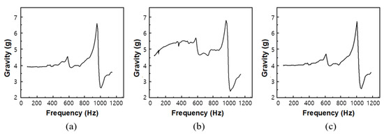
Figure 8.
Natural frequency of the chuck adapter. (a) CFRP, (b) steel, (c) CFRP with steel.

Table 6.
Experimental results of three types of chuck adapters.
3.2. Chuck Adapter Vibration Experiment
Vibration characteristic experiments using the three types of chuck adapters were conducted. The vibration velocity and displacement of the three types of chuck adapters were measured using the Fast Fourier Transform (FFT) method. The vibration source rotated at 10, 500, and 1000 rpm, generating the vibrations; 10 rpm is inoperative and very low speed, 500 rpm is medium speed, 1000 rpm is high speed. These rates were set in consideration of the actual rotation speed used in the machining tool. The vibration velocity and displacement in the bearing and fastening parts were measured. The bearing part generates a lot of vibration in the machining tool, and the fastening part is directly fastened to the machining tool. Both parts are greatly affected by vibration. The vibration speed and displacement of the two parts were measured to compare and analyze the vibration characteristics of the three types of chuck adapters.
3.2.1. Bearing Part Vibration Characteristics
The vibration value of the bearing part was measured to see the vibration value of the chuck adapter. The sensor was attached to the bearing part and the measured data was stored in the computer. The rotational speed of the three kinds of chuck adapter was 10, 500 and 1000 rpm and adjusted the output of the controller. The chuck adapter was run for 30 s, giving the vibration velocity and displacement for each of the 3 kinds of chuck adapter. The time-domain signals were transformed into Fast Fourier Transform to accurately evaluate the vibration performance of the CFRP chuck adapter. The vibration velocity at each rotational speed was analyzed in the frequency domain near the rotation frequency of the chuck adapter, that is, only the rotation vibration of the chuck adapter was considered.
It may be seen in Table 7 that only the rotational vibration of the chuck adapter is considered; the vibration velocity on the bearing part increased as the rotational speed increased, and the velocity increased when the rotational speed increased from 10 rpm to 1000 rpm. The vibration velocity of the CFRP chuck adapter increased by 83%, the steel chuck adapter by 105%, and the steel chuck adapter by 42%. The minimum performance improvement rate of vibration velocity was 5.6% at 10 rpm and the maximum improvement rate of vibration velocity was 18.2% at 1000 rpm on the bearing part.

Table 7.
Vibration velocity of bearing part.
Table 8 shows displacement due to vibration measurement. The displacement of the CFRP chuck adapter increased by 50%, the steel chuck adapter by 33%, and the steel chuck adapter by 47%. The vibration velocity of the CFRP chuck adapter was measured to be the lowest in all rpm conditions. The displacement of the CFRP chuck adapter was lower than that of the steel chuck adapter at 10, 500 rpm, and higher than that of the steel chuck adapter at 1000 rpm. The minimum performance improvement rate of vibration velocity was 5% at 10 rpm, and the maximum rate of vibration velocity improvement was 9% at 500 rpm on the bearing part. Figure 9 shows the performance improvement rate of the CFRP chuck adapter compared to steel in the bearing part. Overall, the CFRP chuck adapter has better vibration velocity reduction than the conventional steel chuck adapter in the bearing part.

Table 8.
Displacement of bearing part.
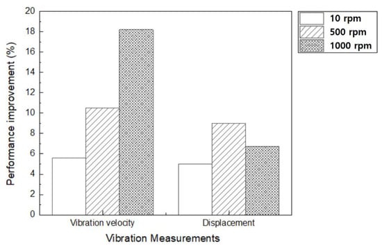
Figure 9.
Performance improvement rate of the CFRP chuck adapter compared to steel in the bearing part.
3.2.2. Fastening Part Vibration Characteristics
The vibration value of the fastening part was measured to determine that of the chuck adapter. The sensor was attached to the fastening part and the measured data were stored on a computer. The rotational speeds of the three types of chuck adapters were synchronized to the output of the controller. The chuck adapter was operated for 30 s, and the vibration velocity and displacement for each of the three kinds of chuck adapter were obtained. The time-domain signals were transformed using the FFT method to evaluate the vibration performance of the CFRP chuck adapter accurately. The vibration velocity at each rotational speed was analyzed in the frequency domain near the rotation frequency of the chuck adapter; that is, only the rotation vibration of the chuck adapter was considered.
The results are shown in Table 9. The vibration velocity of the fastening part increases as the rotational speed increases. The vibration velocity for the CFRP chuck adapter increased by 17%, the steel chuck adapter by 37%, and the steel chuck adapter by 5%. The displacement increased by 6.7% at 1000 rpm and the maximum performance improvement rate of displacement was 9% at 500 rpm on the fastening part. The minimum of performance improvement rate of displacement was 12% at 10 rpm, and the maximum rate of displacement was 64% at 500 rpm on the fastening part.

Table 9.
Vibration velocity of fastening part.
Table 10 shows displacement due to vibration measurement. The displacement for the CFRP chuck adapter increased by 79%, the steel chuck adapter by 108%, and the steel chuck adapter by 40%. The vibration velocity and displacement of the CFRP chuck adapter were the lowest at all rotational speeds. The minimum and maximum performance improvement rates of the vibration velocity for the fastening part were 12.5% and 31.1%, at 500 rpm and 1000 rpm, respectively. Figure 10 shows the performance improvement rate of the CFRP chuck adapter compared to steel in the bearing part. Overall, the CFRP chuck adapter has better or similar displacement than the conventional steel chuck adapter in the fastening part.

Table 10.
Displacement of fastening part.
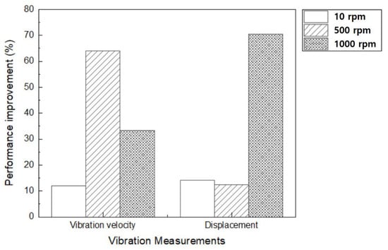
Figure 10.
Performance improvement rate of the CFRP chuck adapter compared to steel in the fastening part.
4. Conclusions
In this study, a CFRP chuck adapter was designed and its natural frequency, vibration velocity, and stability were examined. The vibration velocity reduction during operation of the CFRP chuck adapter was compared with that of the other two types. The following conclusions were drawn.
- A composite material with excellent mechanical performance was manufactured by stacking Onyx materials and carbon fibers using a 3D printer. Appropriate vibration measurement equipment was constructed, and experimental conditions suitable for measurement were selected to measure the vibration velocity and displacement.
- The CFRP chuck adapter had the same vibration shape as a steel chuck adapter and a CFRP with steel chuck adapter, and the natural frequencies of CFRP, steel, and CFRP with steel chuck adapters were presented with an error of 0.4%. The vibration in the stable range was measured for all three types of chuck adapters in the vibration stability test.
- The maximum vibration velocity reduction of the CFRP chuck adapter was 64%, which proved that the vibration velocity of the CFRP chuck adapter was reduced more than the steel chuck adapter. In addition, the maximum displacement reduction of the CFRP chuck adapter was 31.1%, which proved that the displacement of the CFRP chuck adapter was reduced more than the steel chuck adapter.
In this study, a vibration comparison analysis was performed with steel and CFRP chuck adapters. The results of this study are not limited to chuck adapters and can be applied to other parts.
Author Contributions
Conceptualization, M.-J.K. and D.-H.K.; methodology, M.-J.K.; software, J.-H.L.; validation, M.-J.K.; formal analysis, M.-J.K.; investigation, M.-J.K. and D.-H.K.; resources, M.-J.K.; data curation, J.-H.L.; writing—original draft preparation, M.-J.K. and D.-H.K.; visualization, M.-J.K.; writing—review and editing, D.-H.K.; supervision, D.-H.K. and C.-M.L.; project administration, S.-H.K. and C.-M.L.; funding acquisition, S.-H.K. and C.-M.L. All authors have read and agreed to the published version of the manuscript.
Funding
This work was supported by the National Research Foundation of Korea (NRF) grant funded by the Korea government (MSIT) (No. 2019R1A5A8083201).
Institutional Review Board Statement
Not applicable.
Informed Consent Statement
Not applicable.
Data Availability Statement
Data presented in this article are available upon request from the corresponding author.
Conflicts of Interest
The authors declare no conflict of interest.
References
- Jia, Z.; Fu, R.; Niu, B.; Qian, B.; Bai, Y.; Wang, F. Novel Drill Structure for Damage Reduction in Drilling CFRP Composites. Int. J. Mach. Tools Manuf. 2016, 110, 55–65. [Google Scholar] [CrossRef]
- Liu, J.; Zhang, D.; Qin, L.; Yan, L. Feasibility Study of the Rotary Ultrasonic Elliptical Machining of Carbon Fiber Reinforced Plastics (CFRP). Int. J. Mach. Tools Manuf. 2012, 53, 141–150. [Google Scholar] [CrossRef]
- Zhang, J.; Yang, H.; Li, X.; Ye, W. A Method of Reducing Motor Vibration: Natural Frequency, Damping Ratio, and Vibration Analysis of CFRP Motor Frame. Shock. Vib. 2020, 2020, 6021640. [Google Scholar] [CrossRef]
- Druesne, F.; Hallal, J.; Lardeur, P.; Lanfranchi, V. Modal Stability Procedure Applied to Variability in Vibration from Electromagnetic Origin for an Electric Motor. Finite Elem. Anal. Des. 2016, 122, 61–74. [Google Scholar] [CrossRef]
- Mendonça, W.R.D.P.; de Medeiros, E.C.; Pereira, A.L.R.; Mathias, M.H. The Dynamic Analysis of Rotors Mounted on Composite Shafts with Internal Damping. Compos. Struct. 2017, 167, 50–62. [Google Scholar] [CrossRef]
- Troncossi, M.; Taddia, S.; Rivola, A.; Martini, A. Experimental Characterization of a High-Damping Viscoelastic Material Enclosed in Carbon Fiber Reinforced Polymer Components. Appl. Sci. 2020, 10, 6193. [Google Scholar] [CrossRef]
- Virgillito, E.; Sisca, L.; Carello, M. Influence of Freeze-Thaw Aging on the Impact Performance of Damped Carbon Fiber Reinforced Plastics for Automotive Applications. Appl. Sci. 2022, 12, 4020. [Google Scholar] [CrossRef]
- Lin, H.; Xiang, Y.; Yang, Y. Coupled Vibration Analysis of CFRP Cable-Tube System under Parametric Excitation in Submerged Floating Tunnel. Procedia Eng. 2016, 166, 45–52. [Google Scholar] [CrossRef]
- Khazaei Poul, M.; Nateghi-Alahi, F.; Zhao, X.L. Experimental Testing on CFRP Strengthened Thin Steel Plates under Shear Loading. Thin-Walled Struct. 2016, 109, 217–226. [Google Scholar] [CrossRef]
- Capozucca, R.; Bonci, B. Notched CFRP Laminates under Vibration. Compos. Struct. 2015, 122, 367–375. [Google Scholar] [CrossRef]
- Wang, X.-J.; Schmitt, C.; Payne, M.; Adams, R.D.; Bacon, G.C. Measurement of the Flexural Damping Capacity and Dynamic Young’s Modulus of Metals and Reinforced Plastics. J. Phys. D Appl. Phys. 1973, 6, 27–41. [Google Scholar]
- Rueppel, M.; Rion, J.; Dransfeld, C.; Fischer, C.; Masania, K. Damping of Carbon Fibre and Flax Fibre Angle-Ply Composite Laminates. Compos. Sci. Technol. 2017, 146, 1–9. [Google Scholar] [CrossRef]
- Maheri, M.R. The Effect of Layup and Boundary Conditions on the Modal Damping of FRP Composite Panels. J. Compos. Mater. 2011, 45, 1411–1422. [Google Scholar] [CrossRef]
- Abramovich, H.; Govich, D.; Grunwald, A. Damping Measurements of Laminated Composite Materials and Aluminum Using the Hysteresis Loop Method. Prog. Aerosp. Sci. 2015, 78, 8–18. [Google Scholar] [CrossRef]
- Martone, A.; Antonucci, V.; Zarrelli, M.; Giordano, M. A Simplified Approach to Model Damping Behaviour of Interleaved Carbon Fibre Laminates. Compos. B Eng. 2016, 97, 103–110. [Google Scholar] [CrossRef]
- Assarar, M.; Zouari, W.; Ayad, R.; Kebir, H.; Berthelot, J.M. Improving the Damping Properties of Carbon Fibre Reinforced Composites by Interleaving Flax and Viscoelastic Layers. Compos. B Eng. 2018, 152, 248–255. [Google Scholar] [CrossRef]
- Jinguang, Z.; Hairu, Y.; Guozhi, C.; Zeng, Z. Structure and Modal Analysis of Carbon Fiber Reinforced Polymer Raft Frame. J. Low Freq. Noise Vib. Act. Control. 2018, 37, 577–589. [Google Scholar] [CrossRef]
- Hong, Y.; He, X.D.; Wang, R.G. Vibration and Damping Analysis of a Composite Blade. Mater. Des. 2012, 34, 98–105. [Google Scholar] [CrossRef]
- Wen, X.; Li, W.; Fang, Y.; Song, C.; Zhang, J. Design and Vibration Isolation Performance of Truss-Type CFRP Raft Frame. Shock. Vib. 2019, 2019, 4281958. [Google Scholar] [CrossRef]
- Billups, E.K.; Cavalli, M.N. 2D Damping Predictions of Fiber Composite Plates: Layup Effects. Compos. Sci. Technol. 2008, 68, 727–733. [Google Scholar] [CrossRef]
- Ekoi, E.J.; Dickson, A.N.; Dowling, D.P. Investigating the Fatigue and Mechanical Behaviour of 3D Printed Woven and Nonwoven Continuous Carbon Fibre Reinforced Polymer (CFRP) Composites. Compos. B Eng. 2021, 212, 108704. [Google Scholar] [CrossRef]
- Rhakasywi, D.; Marasabessy, A.; Hatuwe, M.R.; Kotahatuhaha, S. Safety Factor of Pump Vibrations on Ships Based on The Natural Frequency of Pump Vibrations According to ISO 10816-3. Safety 2020, 43, 180–192. [Google Scholar]
- Zhu, D.; Tudor, M.J.; Beeby, S.P. Strategies for Increasing the Operating Frequency Range of Vibration Energy Harvesters: A Review. Meas. Sci. Technol. 2010, 21, 022001. [Google Scholar] [CrossRef]
- ISO 20816-1:2016; Mechanical Vibration. International Organization for Standardization: Geneva, Switzerland, 2000. Available online: https://www.iso.org/standard/63180.html (accessed on 11 January 2023).
- ISO 10811-1:2000; Mechanical Vibration and Shock. International Organization for Standardization: Geneva, Switzerland, 2000. Available online: https://www.iso.org/standard/33210.html (accessed on 11 January 2023).
Disclaimer/Publisher’s Note: The statements, opinions and data contained in all publications are solely those of the individual author(s) and contributor(s) and not of MDPI and/or the editor(s). MDPI and/or the editor(s) disclaim responsibility for any injury to people or property resulting from any ideas, methods, instructions or products referred to in the content. |
© 2023 by the authors. Licensee MDPI, Basel, Switzerland. This article is an open access article distributed under the terms and conditions of the Creative Commons Attribution (CC BY) license (https://creativecommons.org/licenses/by/4.0/).