Abstract
This paper presents a novel procedure for the emergency sensorless operation of a six-phase electric drive. More degrees of freedom provided by multiphase technology have been utilized to determine the rotor flux position. The proposed technique is based on the direct measurement of the back EMF generated on a disconnected three-phase winding of a six-phase permanent-magnet synchronous machine (PMSM). The method is suitable for the emergency operation of an electric drive in the case of speed/position sensor failure. The proposed solution has been verified utilizing a six-phase permanent-magnet synchronous machine with a displacement of 30° between two three-phase sets of the stator winding and a power of 1 kW.
1. Introduction
This paper focuses on the sensorless control of six-phase PMSMs. Multiphase machines have been demonstrated as propulsion equipment in the marine industry [1], as generators in windmills power plants [2] and also as propulsion equipment for electric aircrafts [3] and electric vehicles [4]. The reason for the utilization of multiphase machines is the reduction in per-phase current and torque ripple [5]. Their benefit lies also in the improvement in the system redundancy and post-fault characteristics [6]. The six-phase machine with 30° displacement between two three-phase windings is one of the most discussed types of multiphase machines. The dual three-phase solution allows utilization of the standard three-phase power inverters, and the 30° displacement is beneficial for harmonics reduction in the magnetomotive force [7] and produced torque [8].
Sensorless control represents the replacement of the speed/position sensors. The replacement can be permanent, usually for reasons regarding price and space reduction. Sensorless control can also be used as a backup during speed/position sensor failure [9]. In this case, sensorless control is in temporary, emergency operation. The sensorless control of permanent-magnet synchronous machines for low-speed regions utilizes high-frequency signal injection with salience tracking algorithms, which has been applied in [10] to a six-phase PMSM. For middle- and high-speed regions, back-EMF observers are the standard solution [11]. Observers belong to model-based sensorless control techniques, which makes them sensitive to changes in parameters. Stator winding resistance is highly dependent on temperature changes. Synchronous inductances change significantly with the saturation of the magnetic core. The EMF constant changes with temperature and can also be influenced by the flux-productive component in the field-oriented control. The inertia is difficult to define or measure for real complex systems and changes with changes in the system mechanically coupled with the machine. The standard Luenberger-type back-EMF observer in the γδ reference frame has been applied to a six-phase PMSM in [12]. This paper focuses on middle- and high-speed sensorless control for a six-phase PMSM, utilizing a new procedure that can be applied to multiphase electric drives as a promising alternative to back-EMF observers. The proposed method is similar to the search coil method, where an additional winding is placed in the stator [13]. The search coil usually has only a few turns with a small cross section and represents the inbuilt resolver. With the method proposed in this paper, additional sensors such as search coils and resolvers are not required, and one three-phase set of the six-phase stator winding is utilized instead. The proposed method is applicable to multiphase permanent-magnet synchronous machines. A six-phase PMSM with field-oriented control (FOC) and the vector space decomposition (VSD) method [14] have been utilized in this work. The speed and the position of the rotor are obtained via the resolver in healthy conditions (Section 5), and via the novel sensorless procedure in the case of resolver failure (Section 6). In an emergency operation, the drive continues with reduced power since only one three-phase winding is utilized for torque generation, while the disconnected winding is used as the back-EMF sensor. The drive can also operate at the nominal power if the system is designed for the overload conditions, which usually applies to discontinuous operation.
2. Mathematical Model of Six-Phase PMSM
The mathematical model of the six-phase PMSM can be constructed as the model of the dual three-phase machine (1) and (2) [15]. To each three-phase system corresponds one torque- and flux-productive subspace d1–q1 and d2–q2. Parameters Ld1, Lq1, Ld2 and Lq2 represent synchronous inductances of the first and the second three-phase windings, while Md12 and Mq12 are mutual inductances between them. The size of the mutual coupling between partial three-phase systems in comparison to synchronous inductances is shown in (3) and (4), where M is the mutual inductance between two phases placed in the same position.
Another procedure for the construction of the mathematical model of the six-phase machine is the vector space decomposition (VSD) method [14]. The method represents the harmonics segregation in partial orthogonal subspaces. Only one subspace d–q is torque- and flux-productive (5), which covers the basic harmonic and harmonics of the order 12k ± 1 (k = 1, 2, 3, …). The additional subspace z1–z2 is created (6) to cover all degrees of freedom in the six-phase machine. The subspace z1–z2 includes harmonics of the order 6k ± 1 (k = 1, 3, 5, …) and represents the difference between the partial subspaces d1–q1 and d2–q2 defined in (1) and (2).
The mutual coupling between two three-phase systems is not present in the vector space decomposition procedure, as the changes between partial systems are moved to the z1–z2 subsystem. The value of the synchronous inductances Ld and Lq from the model (5) and (6) is defined in (7). Comparing dual three-phase and VSD mathematical models, the relation between inductances can be defined as shown in (8) and (9).
Rs is a resistance, and Lσ is a leakage inductance of one stator phase. They remain the same in both modeling procedures since they correspond only to the main diagonal in the mathematical model regarding phase coordinates. ωe is the electrical angular speed of the rotor, and ψpm is the EMF constant. The subsystem z1–z2 defined in (6) is in the stationary reference frame, while the d–q subspaces defined in (1), (2) and (5) are in the synchronous reference frame. The electromagnetic torque generated by the machine is defined with the VSD approach in (10), where p is the number of pole pairs.
The torque constant Kt is defined in (11) and represents the relation between synchronous torque and the stator current, as can be identified in (10). m represents the number of phases and c is the coefficient of proportion, which is in the amplitude-invariant VSD method for the six-phase machine, equal to 2/6. The coefficient, and subsequently also the torque constant, changes with the number of active phases.
3. Field-Oriented Control with Vector Space Decomposition
The control structure shown in Figure 1 is based on the vector space decomposition procedure [16]. Field-oriented control is achieved by controlling only one torque- and flux-productive subspace d–q for the whole six-phase machine. The transformation of vector space decomposition from phase coordinates to partial orthogonal subspaces is defined in (12)–(17). The coefficient K represents the amplitude-invariant behavior for the six-phase (K = 0.5) and three-phase (K = 1) operations.
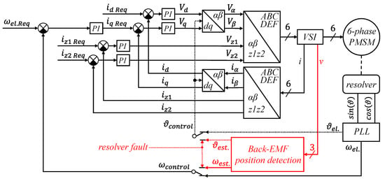
Figure 1.
Field-oriented control structure with the vector space decomposition method, and emergency detection of the rotor speed/position.
The resultant α–β subspace is transformed to the synchronous reference frame utilizing the standard Park transformation (18), where ϑe is the electrical position of the rotor flux.
The transformation of reference voltages in the inverse path is realized similarly to the transformations shown in (12)–(18), considering the inverse form of the transformation matrices. The subspace z1–z2 is controlled in the stationary reference frame. Currents iz1 and iz2 are controlled to zero to keep the six-phase operation in balanced conditions. The difference between amplitudes of phase currents in partial three-phase systems (the current sharing problem) and the harmonics of the order 6k ± 1 (k = 1, 3, 5, …) are then eliminated. Since the required values for the z1–z2 subspace are constant DC values (zero), the PI controllers can be used for the control of currents iz1 and iz2. Otherwise, resonant controllers would be required. The speed loop of the field-oriented control has been set by the pole placement method, where the transfer function of the current loop has been considered as the unity gain. The current controllers for d–q currents have been set by the zero-pole cancelation method, where the integration time constant of the PI controller is equal to the time constant of the RL circuit represented by the machine winding.
4. Back-EMF Processing
Detection of the back-EMF position (Figure 2) is based on the phase-locked loop (PLL) method. Three-phase voltages measured on the second system D–E–F are shifted from the first system A–B–C by 30°. Utilizing the transformation shown in (13) are α–β voltages aligned with the correct reference frame, where phase A, as well as the α component, start at the zero position as the sine function (Figure 3). The PI controller in the PLL forces the difference between the electrical rotor position ϑe and the estimated position ϑest. to zero. The procedure estimates the electrical rotor speed ωest. without derivation.

Figure 2.
Emergency detection unit of the rotor speed/position.

Figure 3.
Simulation of the transformation between phase coordinates D–E–F to the stationary α–β subspace at the zero-position reference frame.
The transformation from a symmetrical three-phase system into the orthogonal subsystem brings the ability of zero-sequence components (harmonics of the order 3k, where k = 1, 3, 5, …) and the DC offset segregation, as shown in Figure 4a. However, it is not able to exclude harmonics of the orders 12k ± 1 (k = 1, 2, 3, …) and 6k ± 1 (1, 3, 5, …), as shown in Figure 4b.
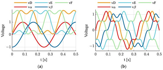
Figure 4.
Simulation of the transformation between phase coordinates D–E–F to the stationary α–β subspace at the zero-position reference frame: (a) basic harmonic with the third harmonic and the DC offset; (b) basic harmonic with the fifth harmonic.
5. Operation Mode with the Healthy Speed/Position Sensor
The healthy operation of the six-phase PMSM drive is presented in Figure 5, Figure 6, Figure 7, Figure 8, Figure 9 and Figure 10, followed by the back-EMF investigation in the three-phase operation (Figure 11, Figure 12, Figure 13 and Figure 14). In this case, the speed/position feedback is obtained from the resolver (sensor-based control).

Figure 5.
Phase current during the startup transient of the six-phase operation.
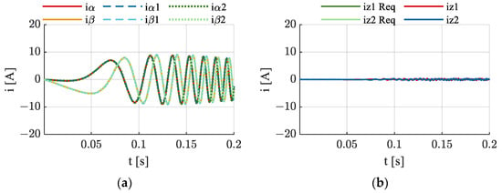
Figure 6.
Current in transformed subsystems during the startup transient of the six-phase operation: (a) α–β subsystems; (b) z1–z2 subsystem.
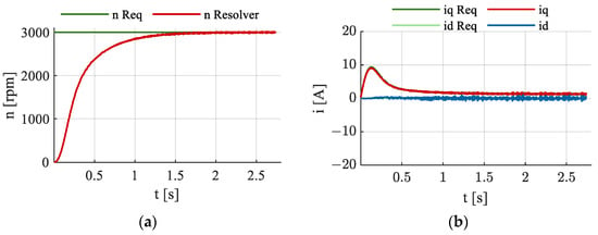
Figure 7.
Startup transient of the six-phase operation: (a) rotor speed; (b) current in d–q subsystem.
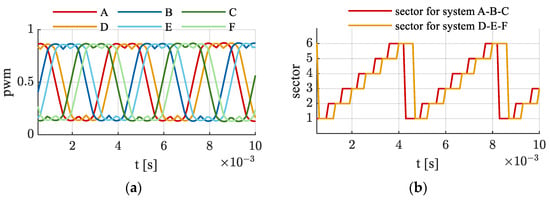
Figure 8.
Double zero-sequence SVM during the steady-state six-phase operation: (a) PWM references; (b) SVM sectors.

Figure 9.
Oscilloscopic record of the measured voltage during the steady-state six-phase operation.
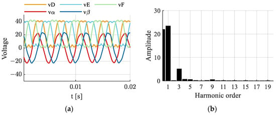
Figure 10.
Measured voltages during the steady-state six-phase operation: (a) measured phase voltages and their transformed α–β components; (b) frequency spectrum of the measured voltage vF.

Figure 11.
Phase current during the startup transient of three-phase operation.

Figure 12.
Oscilloscopic record of the measured voltage during the steady-state three-phase operation.
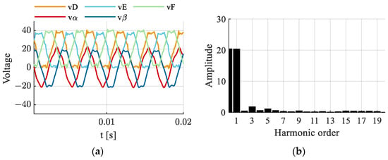
Figure 13.
Measured voltages during the steady-state three-phase operation: (a) measured phase voltages and their transformed α–β components; (b) frequency spectrum of the measured voltage vF.
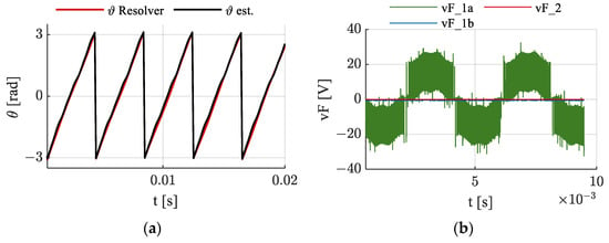
Figure 14.
Steady-state three-phase operation: (a) electrical rotor position measured by resolver and estimated from back-EMF voltages D, E and F; (b) oscilloscopic record of the measured voltage.
Currents of the z1–z2 subspace are controlled to zero, which eliminates the differences between partial α–β components (Figure 6a,b). This technique also eliminates the current sharing problem [16] and the harmonic disturbance from the phase current [17], as shown in Figure 5.
The startup in the speed loop control from 0 to 3000 rpm is shown in Figure 7a. The maximal current of the machine is 19 A, so the dynamic of the speed controller for the standard six-phase operation can be set higher, as shown in Figure 7b. However, the dynamic has been set according to the three-phase operation, wherein the startup current reaches the maximum, as shown in Figure 11.
The dual zero-sequence SVM technique [18] has been utilized for the generation of PWM references (Figure 8). The modulation has been realized using inverse transformation (depicted in Figure 1) with the injection of the third harmonic saw. The third harmonic injection allows us to increase the DC-bus voltage utilization so the machine can reach a higher speed than that of the purely sinusoidal PWM references.
The PWM references with the third harmonic are also beneficial in this experiment for the recognition of the source voltage’s influence on measured voltages. Voltage measured with an oscilloscope on phase F is shown in Figure 9. The DC-bus voltage of the application is 45 V, which corresponds to the PWM pulses measured on the phase connector of the power inverter (vF_1). The voltage signal is then filtered with hardware filters and amplified by an operational amplifier (vF_2). The voltage signal is sampled by a microcontroller (vF), which is shown in Figure 10. Measured voltages are a combination of the power supply voltage and the back-EMF voltage, so the estimated position from this operation does not correspond to the actual electrical position of the rotor flux.
The three-phase operation is presented in the following part of the paper to investigate the back-EMF behavior in the disconnected system. The second three-phase winding is not supplied to eliminate the influence of the stator voltage on the measured voltage. Both top and bottom transistors of phases D, E and F in the power inverter are turned off.
The control structure is still in the VSD form (Figure 1). However, specific modifications are required. The control of the z1–z2 subspace is turned off by setting voltages Vz1 and Vz2 to zero. Currents in the z1–z2 subspace behave as defined in (16) and (17), considering the second α–β subspace to be equal to zero. The coefficient K in (14)–(17) is changed to K = 1, so the control remains amplitude-invariant, and the coefficient of proportion changes to 2/3. The torque constant is then, according to (11), reduced to half. Based on (1)–(9), synchronous inductances of the VSD model Ld and Lq are changed to the synchronous inductances of the first three-phase system Ld1 and Lq1 (3). Modified values of parameters are used for the readjustment of the FOC controllers. Supply voltages and currents flowing through phases D, E and F are now zero. The measured voltage (Figure 12) then theoretically corresponds only to the back EMF produced by the flux of permanent magnets. The elimination of the supply voltage with the third harmonic from the measured voltages can be seen in the frequency spectra in Figure 13. The remaining third and fifth harmonics are generated with the EMF of the machine, but also through the armature reaction.
The position (Figure 14a) has been estimated from transformed α–β components (Figure 13a) using the PLL method shown in Figure 2. The third harmonic and the DC offset have been separated during the transformation, which does not apply to the fifth harmonic, as can be seen in Figure 13a. This fact confirms the results from Figure 4. The utilized PLL has a filtrating characteristic. Harmonics of the orders 6k ± 1 (k = 1, 3, 5, …) and 12k ± 1 (k = 1, 2, 3, …), which are not segregated during the transformation process, are damped with the PI controller in the PLL structure. However, to keep the dynamic of the observer useful for control procedures, the damping property cannot be set too high, and the remaining harmonics can appear at the observed speed and position. Therefore, the proposed method is more appropriate for machines with a negligible fifth harmonic of the EMF. The switching frequency can still be observed in the measured voltage (Figure 12). The machine winding of the second system D–E–F has been physically disconnected from the inverter to identify the source of this signal, which is possible in the sensor-based three-phase operation (Figure 14b). The voltage has been measured separately on the machine winding (vF_1a) and the connector of the inverter (vF_1b). The signal with the switching frequency is generated through the machine, and the source is the first set of the active stator winding A–B–C.
6. Operation Mode with the Faulty Speed/Position Sensor
The emergency three-phase operation is shown in this part of the paper. A resolver fault is assumed. The control procedure is the same as the three-phase operation mode described in the previous section, except for the speed/position feedback, which is now obtained from back-EMF voltages measured on the winding of the second system D–E–F. The results for sensorless control are presented in Figure 15, Figure 16, Figure 17, Figure 18, Figure 19 and Figure 20. The value of the back EMF is proportional to the rotor speed, so the proposed method does not work in the low-speed region. This technique is based on the phase angle of measured voltages, and the position of the measured three-phase signal is unrecognizable in the noise if the amplitude is small. The results of the acceleration from 300 rpm to 3000 rpm are shown in Figure 15, Figure 16 and Figure 17. Data from the resolver are shown in Figure 17, Figure 19 and Figure 20 only to verify the correctness of the estimated speed/position, and they are not used in the control algorithm. The startup shown in Figure 17 has been executed for no-load conditions.

Figure 15.
Phase current during the startup transient of the emergency three-phase operation.
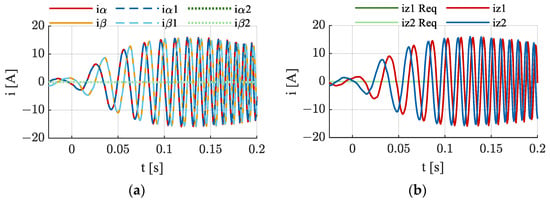
Figure 16.
Current in transformed subsystems during the startup transient of the emergency three-phase operation: (a) α–β subsystems; (b) z1–z2 subsystem.
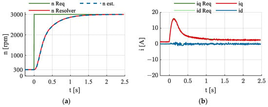
Figure 17.
Startup transient of the emergency three-phase operation: (a) rotor speed; (b) current in d–q subsystem.
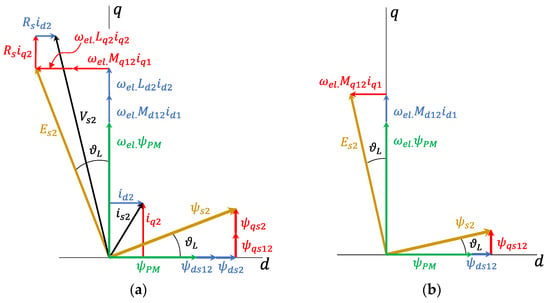
Figure 18.
Vector diagram of the second three-phase system D–E–F in the synchronous reference frame: (a) six-phase operation; (b) three-phase operation.
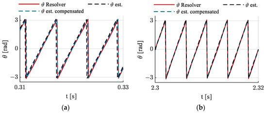
Figure 19.
Electrical rotor position: (a) startup transient of the emergency three-phase operation at approximately 2000 rpm; (b) no-load steady state of the emergency three-phase operation at 3000 rpm.
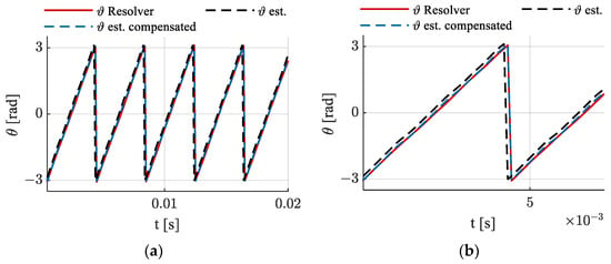
Figure 20.
Electrical rotor position: (a) load steady state of the emergency three-phase operation; (b) zoom of the load steady state at the emergency three-phase operation.
As follows from the mathematical model (1)–(4), the increase in the stator current in the active winding generates an induced voltage in the disconnected winding. This state creates a phenomenon called the armature reaction. The position of the measured voltage represented by the space vector Es2 is displaced from the actual rotor flux position by the load angle ϑL, as shown in Figure 18 [19]. The armature reaction is compensated, as described in (19) and (20), where the flux-producing component of the stator current is considered to be equal to zero.
The position behavior corresponding to the no-load startup (Figure 17) is shown for the transient at approximately 2000 rpm in Figure 19a. The steady-state operation at 3000 rpm is presented in Figure 19b. The next test was performed at the steady-state 3000 rpm operation, where the mechanical load was increased by the DC machine with 0.5 kW power coupled mechanically to the tested six-phase PMSM. The load torque is at the level corresponding to 9 A of the stator current in the three-phase operation of the six-phase PMSM.
The compensation of the position error due to the mutual coupling between two sets of three-phase windings is based on the mutual inductances and the voltage constant, as defined in (19). The position correction can be affected by a change in parameters. However, the portion of the q-axis mutual cross-coupling is much lower than what is sketched in Figure 18. The real value of the position displacement is shown in Figure 20. The compensation is used only as the position corrector after the estimation process, so the speed is not directly influenced by the parameters, as is standard for many model-based back-EMF observers. Experimental verification presented in Section 5 and Section 6 has been executed on the setup shown in Figure 21. Data have been captured utilizing the FreeMaster software tool (NXP) and imported to MATLAB. The six-phase PMSM has been supplied utilizing the six-phase inverter controlled by the microprocessor S32K344 (NXP semiconductors). Parameters of the machine are listed in Table 1.
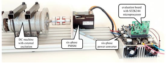
Figure 21.
Setup used for the experimental verification.

Table 1.
Machine parameters.
7. Conclusions
This paper focuses on a novel alternative for the emergency sensorless control of a six-phase PMSM that is less parameter-dependent than standard back-EMF observers. The proposed solution is useful as a backup in the case of a speed/position sensor failure in the middle- and high-speed regions. In the case of a sensor fault, the second three-phase winding of the six-phase machine is disconnected, and the machine continues with reduced power or in overloaded conditions. The sensorless technique is based on the estimation of the rotor position from the back-EMF measured on the disconnected winding. The proposed method is appropriate for six-phase PMSMs with two symmetrical three-phase windings because of the processing based on the goniometric functions. The healthy six-phase operation was proposed at first, following the investigation of the three-phase control mode. The change in parameters between the six-phase and three-phase modes has been described and utilized to readjust the FOC controllers. The mutual coupling in the form of the armature reaction has been investigated, and its compensation has been designed based on the vector diagram. The proposed emergency sensorless control method has been verified experimentally between 300 rpm and 3000 rpm at various load conditions. The control has been applied to a six-phase permanent-magnet synchronous machine with a power of 1 kW and 30° displacement between two sets of three-phase windings.
Author Contributions
Conceptualization, M.F.; methodology, M.F. and P.M.; software, M.F.; validation, M.F.; formal analysis, M.F.; investigation, M.F.; resources, M.F.; data curation, M.F.; writing—original draft preparation, M.F.; writing—review and editing, P.M.; visualization, M.F.; supervision, P.M.; project administration, P.R.; funding acquisition, P.R. All authors have read and agreed to the published version of the manuscript.
Funding
This research was funded by the Slovak Scientific Grant Agency VEGA No. 1/0768/22 and the Slovak Scientific Grant Agency VEGA for project support 688 1/0795/21.
Institutional Review Board Statement
Not applicable.
Informed Consent Statement
Not applicable.
Data Availability Statement
Not applicable.
Conflicts of Interest
The authors declare no conflict of interest.
References
- Kuznetsov, S. Machine design and configuration of a 7000 hp hybrid electric drive for naval ship propulsion. In Proceedings of the IEEE International Electric Machines & Drives Conference, Niagara Falls, ON, Canada, 15–18 May 2011. [Google Scholar]
- Duran, M.J.; Kouro, S.; Wu, B.; Levi, E.; Barrero, F.; Alepuz, S. Six-phase PMSG wind energy conversion system based on medium-voltage multilevel converter. In Proceedings of the 14th European Conference on Power Electronics and Applications, Birmingham, UK, 30 August–1 September 2011. [Google Scholar]
- Anton, F. eAircraft: Hybrid-elektrische Antriebe für Luftfahrzeuge. Siemens AG 2019, BBAA. Available online: https://www.bbaa.de/fileadmin/user_upload/02-preis/02-02-preistraeger/newsletter-2019/02-2019-09/02_Siemens_Anton.pdf (accessed on 6 December 2022).
- Riveros, J.; Bogado, B.; Prieto, J.; Barrero, F.; Toral, S.; Jones, M. Multiphase machines in propulsion drives of electric vehicles. In Proceedings of the 14th International Power Electronics and Motion Control Conference (EPE/PEMC), 2010 14th International, Ohrid, Macedonia, 6–8 September 2010; ISBN 978-1-4244-7855-2. [Google Scholar]
- Dhulipati, H.; Iyer, K.L.V.; Mukundan, S.; Mukherjee, K.; Tjong, J.; Kar, N.C. Investigation of 6-phase surface PM machines with concentrated windings for reduction in space harmonics, leakage inductance and magnet loss in direct-drive EV. In Proceedings of the 2016 XXII International Conference on Electrical Machines (ICEM), Lausanne, Switzerland, 4–7 September 2016; ISBN 978-1-5090-2538-1. [Google Scholar]
- Che, H.S.; Duran, M.J.; Levi, E.; Jones, M.; Hew, W.P.; Rahim, N.A. Postfault operation of an asymmetrical six-phase induction machine with single and two isolated neutral points. IEEE Trans. Power Electron. 2013, 29, 5406–5416. [Google Scholar] [CrossRef]
- Furmanik, M.; Staňo, M.; Rafajdus, P. Analytical Exploration of Harmonics Behavior in Multiphase Machines. In Proceedings of the ICEM 2022, Valencia, Spain, 5–8 September 2022; ISBN 978-1-6654-1432-6. [Google Scholar]
- Dhulipati, H.; Mukundan, S.; Li, W.; Tjong, J.; Kar, N.C. Investigation of phase angle displacement in six-phase PMSM with concentrated windings for reduced MMF harmonics. In Proceedings of the IEEE 21st ICEMS 2018, Jeju, Republic of Korea, 7–10 October 2018; ISBN 978-89-86510-20-1. [Google Scholar]
- Rehorik, K.; Elsman, A.; Grothmann, B.; Reiland, N.; Gerling, D.; Capponi, F.G. Position-sensorless control design for safety-relevant steer-by-wire applications. In Proceedings of the ECCE 2020, Detroit, MI, USA, 11–15 October 2020. [Google Scholar]
- Pulvirenti, M.; Rù, D.D.; Bianchi, N.; Scarcella, G.; Scelba, G. Secondary saliences decoupling technique for self-sensing integrated multi-drives. In Proceedings of the SLED 2016, Nadi, Fiji, 5–6 June 2016. [Google Scholar]
- Kim, H.; Harke, M.C.; Lorenz, R.D. Sensorless control of interior permanent-magnet machine drives with zero-phase lag position estimation. IEEE Trans. Ind. Appl. 2003, 39, 1726–1733. [Google Scholar]
- Scelba, G.; Scarcella, G.; Cacciato, M.; Pulvirenti, M.; Testa, A. Compensation of rotor position estimation errors in sensorless dual-three phase PMSM drives through back-EMF sensing. In Proceedings of the SLED 2017, Catania, Italy, 18–19 September 2017. [Google Scholar]
- Tornello, L.D.; Scelba, G.; Scarcella, G.; Cacciato, M.; Testa, A.; Foti, S.; Caro, S.; Pulvirenti, M. Combined Rotor-Position Estimation and Temperature Monitoring in Sensorless, Synchronous Reluctance Motor Drives. IEEE Trans. Ind. Appl. 2019, 55, 3851–3862. [Google Scholar] [CrossRef]
- Zhao, Y.; Lipo, T.A. Space vector PWM control of dual three-phase induction machine using vector space decomposition. IEEE Trans. Ind. Appl. 1995, 31, 1100–1109. [Google Scholar] [CrossRef]
- Karttunen, J.; Kallio, S.; Peltoniemi, P.; Silventoinen, P.; Pyrhönen, O. Dual three-phase permanent magnet synchronous machine supplied by two independent voltage source inverters. In Proceedings of the International Symposium on Power Electronics, Electric Drives, Automation and Motion, Sorrento, Italy, 20–22 June 2012. [Google Scholar]
- Che, H.S.; Levi, E.; Jones, M.; Hew, W.P. Current control methods for an asymmetrical six-phase induction motor drive. IEEE Trans. Power Electron. 2014, 29, 407–417. [Google Scholar] [CrossRef]
- Furmanik, M.; Vidlak, M.; Rafajdus, P. Current Harmonics Control in Six-Phase PMSM. In Proceedings of the 2022 ELEKTRO (ELEKTRO), Krakow, Poland, 23–26 May 2022. [Google Scholar]
- Prieto, J.; Levi, E.; Barrero, F.; Toral, S. Output current ripple analysis for asymmetrical six-phase drives using double zero-sequence injection PWM. In Proceedings of the 37th Annual Conference of the IEEE Industrial Electronics Society, Melbourne, Australia, 7–10 November 2011; 2011. [Google Scholar]
- Miller, T.J.E.; McGlip, M.I. Analysis of multi-phase permanent-magnet synchronous machines. In Proceedings of the IEEE ICEMS, Tokyo, Japan, 15–18 November 2009; ISBN 978-1-4244-5177-7. [Google Scholar]
Disclaimer/Publisher’s Note: The statements, opinions and data contained in all publications are solely those of the individual author(s) and contributor(s) and not of MDPI and/or the editor(s). MDPI and/or the editor(s) disclaim responsibility for any injury to people or property resulting from any ideas, methods, instructions or products referred to in the content. |
© 2023 by the authors. Licensee MDPI, Basel, Switzerland. This article is an open access article distributed under the terms and conditions of the Creative Commons Attribution (CC BY) license (https://creativecommons.org/licenses/by/4.0/).