
Estimation of Impact Loads Transmitted to Vibro-Ripper Housing Using Transfer Path Analysis

 and
and
Abstract
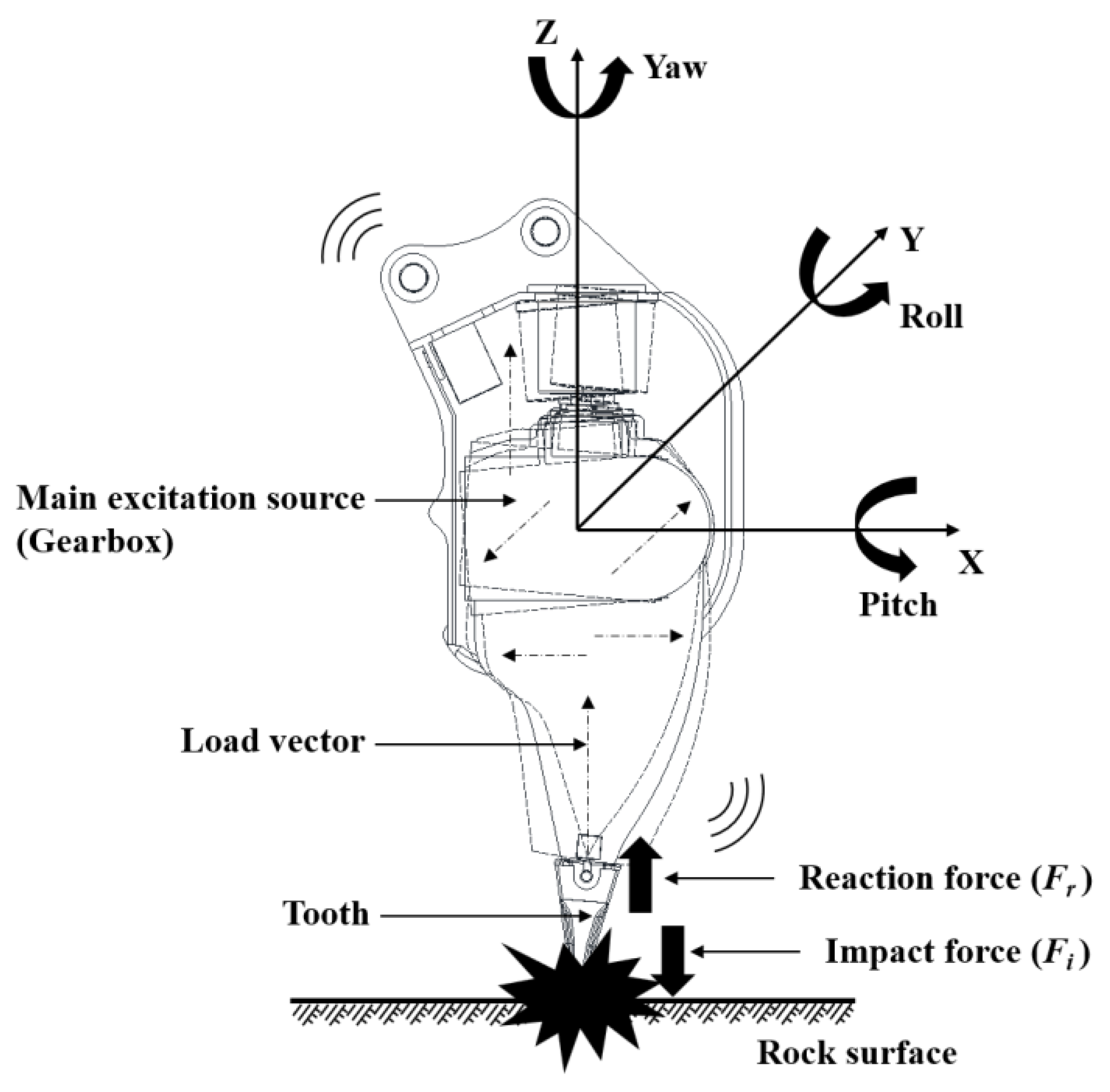
:1. Introduction
2. Vibration Experiments with a Vibro-Ripper
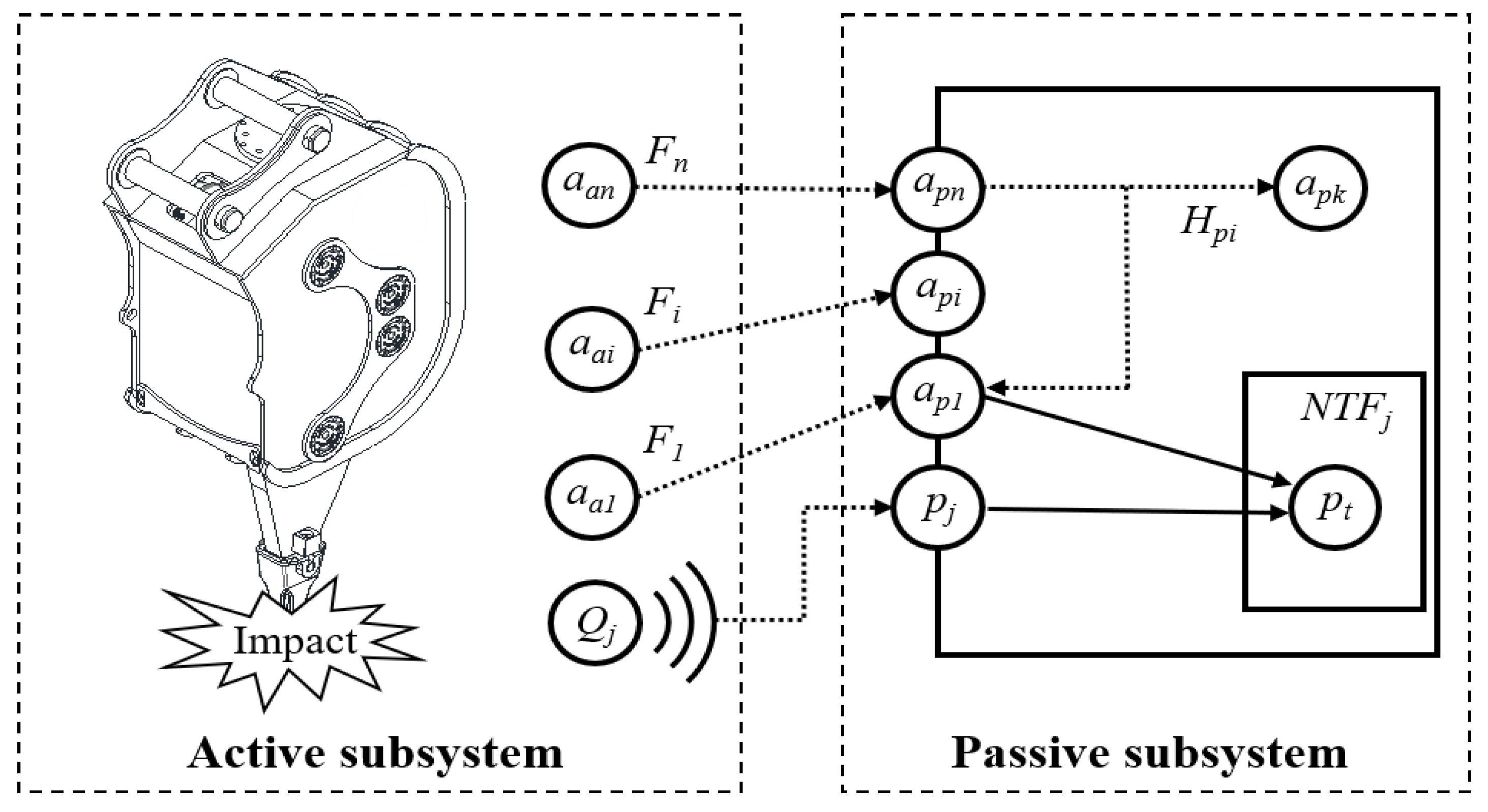
2.1. Theoretical Background of Transfer Path Analysis
2.2. Frequency Domain Analysis of TPA
2.3. Time Domain Analysis of TPA
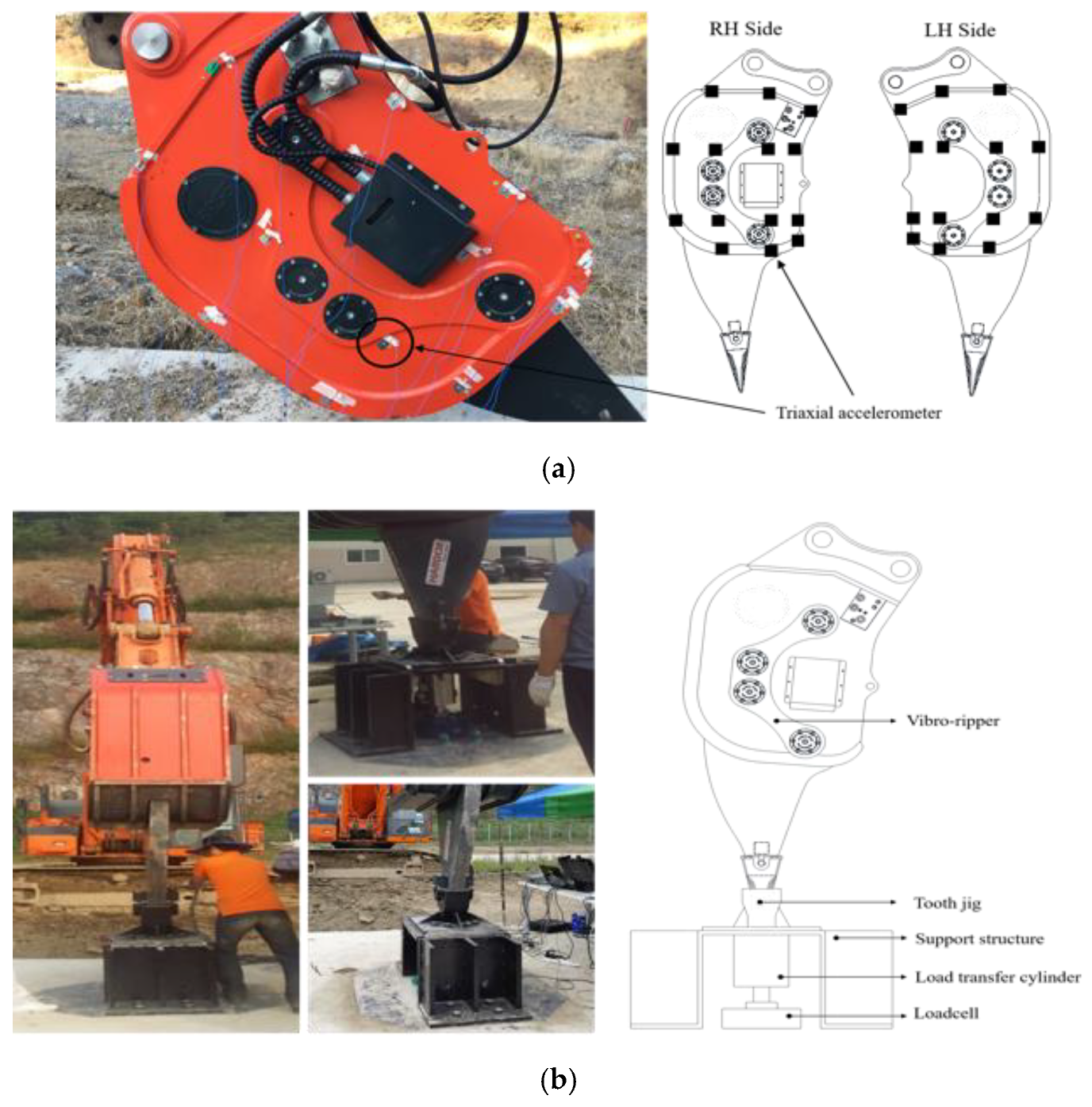
2.4. Vibration Experiment Setup
2.5. Striking Force Measurement
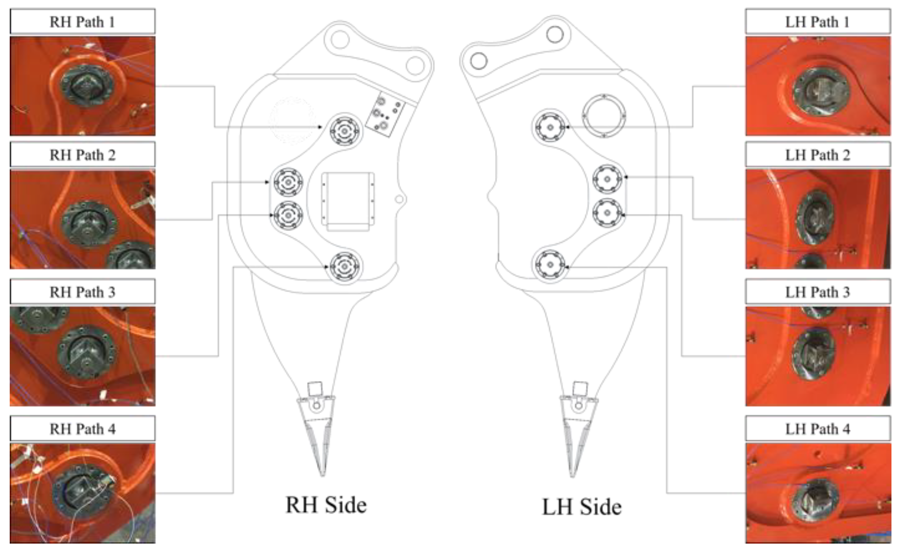
2.6. Selection of Load Transfer Path
2.7. Acquisition of Transfer Function in the Modal Experiment
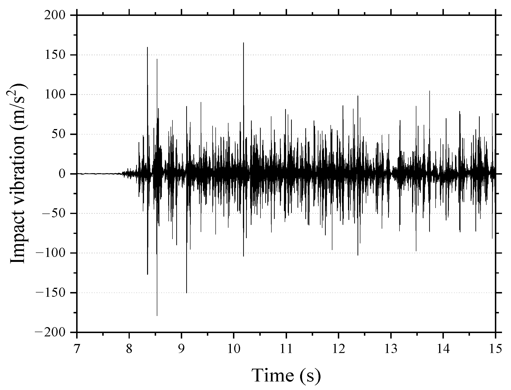
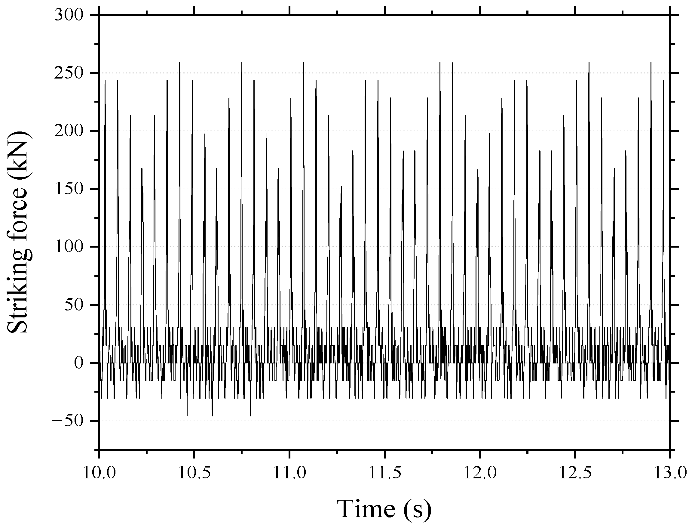
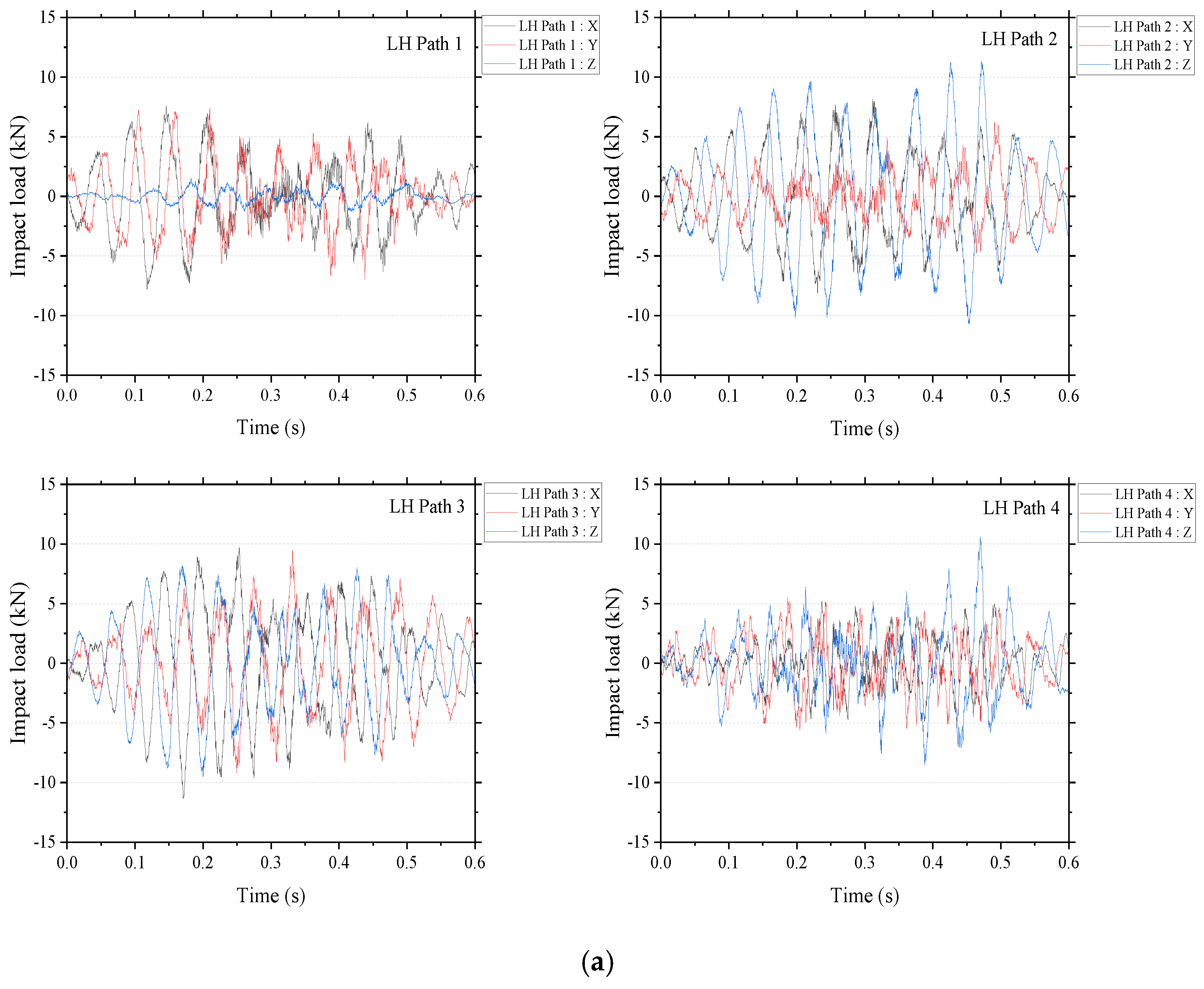
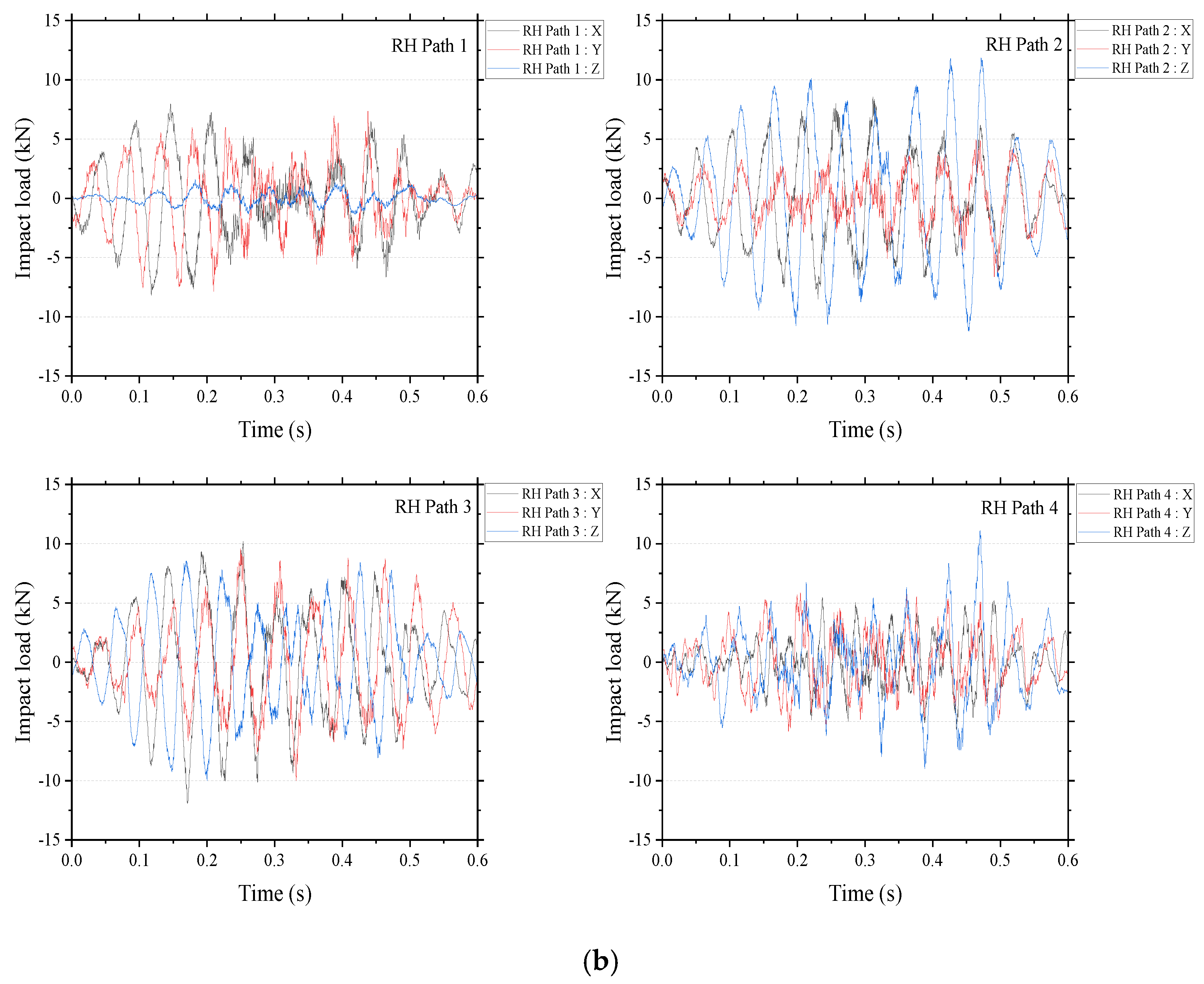
3. Results and Discussion
4. Conclusions
Author Contributions
Funding
Institutional Review Board Statement
Informed Consent Statement
Data Availability Statement
Acknowledgments
Conflicts of Interest
References
- Jonck, J.; Slabbert, G.A. Analysis of a failed spur gear from a vibro-hammer. Eng. Fail. Anal. 2013, 34, 511–518. [Google Scholar] [CrossRef]
- Chen, F.Q.; Wang, J.W.; Li, D.Y.; Qiao, W.G. Application and advance of vibratory driving techniques using high-frequency hydraulic vibratory hammer. Chin. J. Geotech. Eng. 2011, 33, 224–231. (In Chinese) [Google Scholar]
- Xu, G.N.; He, M.; Wu, J.F. Transient vibration analysis of impact ripper. Appl. Mech. Mater. 2014, 551, 150–157. [Google Scholar] [CrossRef]
- Oh, K.K.; Kim, J.; Park, J.Y.; Yang, G.; Park, J.; Kim, S.H. Evaluation of fatigue life of welded joint of gear box-shank in vibro ripper using PSN curve. Trans. Korean Soc. Mech. Eng. A 2015, 39, 1207–1212. (In Korean) [Google Scholar] [CrossRef]
- Lee, S.; Yoon, K.; Kim, E. A Study on Mechanical Vibrational Properties of Vibro-hammer. J. Korean Soc. Hazard Mitig. 2013, 13, 107–112. (In Korean) [Google Scholar] [CrossRef]
- Ficarella, A.; Giuffrida, A.; Laforgia, D. Numerical investigations on the working cycle of a hydraulic breaker: Off-design performance and influence of design parameters. Int. J. Fluid Power 2006, 7, 41–50. [Google Scholar] [CrossRef]
- Ficarella, A.; Giuffrida, A.; Laforgia, D. Investigation on the impact energy of a hydraulic breaker. In SAE Technical Paper; SAE International: Warrendale, PA, USA, 2007. [Google Scholar]
- Ficarella, A.; Giuffrida, A.; Laforgia, D. The effects of distributor and striking mass on the performance of a hydraulic impact machine. In SAE Technical Paper; SAE International: Warrendale, PA, USA, 2008. [Google Scholar]
- Lee, S.H.; Han, C.S.; Song, C.S. A study on the performance improvement of a high efficiency hydraulic breaker. J. Korean Soc. Tribol. Lubr. Eng. 2003, 19, 59–64. [Google Scholar]
- Kim, B.S.; Kim, M.G.; Byun, D.W.; Lee, S.M.; Lee, S.H. A study on the structure improvement of bracket housing for structural noise and vibration reduction in hydraulic. J. Korean Soc. Precis. Eng. 2006, 23, 108–115. (In Korean) [Google Scholar]
- Park, G.B.; Park, C.H.; Park, Y.S.; Choi, D.H. Optimal design for minimizing weight of housing of hydraulic breaker. Trans. Korean Soc. Mech. Eng. A 2011, 35, 207–212. (In Korean) [Google Scholar] [CrossRef]
- Song, C.; Kim, D.J.; Chung, J.; Lee, K.W.; Kweon, S.S.; Kang, Y.K. Estimation of impact loads in a hydraulic breaker by transfer path analysis. Shock Vib. 2017, 2017, 8564381. [Google Scholar] [CrossRef]
- Baker, W.E.; Dove, R.C. Measurement of internal strain in a bar subjected to longitudinal impact. Exp. Mech. 1962, 2, 307–311. [Google Scholar] [CrossRef]
- Suzuki, S. Measured dynamic-load factors of cantilever beams, frame structures and rings subjected to impact loads. Exp. Mech. 1971, 11, 76–81. [Google Scholar] [CrossRef]
- Knapp, J.; Altmann, E.; Niemann, J.; Wemer, K.D. Measurement of shock events by means of strain gauges and accelerometers. Measurement 1998, 24, 87–96. [Google Scholar] [CrossRef]
- Shepherd, C.J.; Thomas, G.J.A.; Wilgeroth, J.M.; Hazell, P.J.; Allsop, D.F. On the response of ballistic soap to one-dimensional shock loading. Int. J. Impact Eng. 2011, 38, 981–988. [Google Scholar] [CrossRef]
- Xue, X.; Ren, T.; Zhang, W. Analysis of fatigue damage character of soil under impact load. J. Vib. Control 2013, 19, 1728–1737. [Google Scholar] [CrossRef]
- Hashiba, K.; Fukui, K.; Liang, Y.Z.; Koizumi, M.; Matsuda, T. Force-penetration curves of a button bit generated during impact penetration into rock. Int. J. Impact Eng. 2015, 85, 45–56. [Google Scholar] [CrossRef]
- Zhang, J.; Guo, S.L.; Wu, Z.S.; Zhang, Q.Q. Structural identification and damage detection through long-gauge strain measurements. Eng. Struct. 2015, 99, 173–183. [Google Scholar] [CrossRef]
- Asbjörnsson, G.; Bengtsson, M.; Hulthén, E.; Evertsson, M. Modelling of discrete downtime in continuous crushing operation. Miner. Eng. 2016, 98, 22–29. [Google Scholar] [CrossRef]
- Kim, S.J.; Lee, S.K. Prediction of interior noise by excitation force of the powertrain based on hybrid transfer path analysis. Int. J. Automot. Technol. 2008, 9, 577–583. [Google Scholar] [CrossRef]
- SIEMENS. Technical Info Issued: What is Transfer Path Analysis. 2014. Available online: http://www.plm.automation.siemens.com/en_us/products/lms/testing/transfer-path-analysis.shtml#lightview-close (accessed on 10 May 2017).
- Qian, K.; Hou, Z.; Liang, J.; Liu, R.; Sun, D. Interior sound quality prediction of pure electric vehicles based on transfer path synthesis. Appl. Sci. 2021, 11, 4385. [Google Scholar] [CrossRef]
- Gajdatsy, P.; Janssens, K.; Desmet, W.; Auweraer, H.V. Application of the transmissibility concept in transfer path analysis. Mech. Syst. Signal Process. 2010, 24, 1963–1976. [Google Scholar] [CrossRef]
- Kahraman, S.; Bilgin, N.; Feridunoglu, C. Dominant rock properties affecting the penetration rate of percussive drills. Int. J. Rock Mech. Min. Sci. 2003, 40, 711–723. [Google Scholar] [CrossRef]


| Items | Parameters | Values |
|---|---|---|
| Tracking | Measurement method | Time trace |
| Duration | 30 s | |
| Increment | 0.5 s | |
| Acquisition | Bandwidth | 6400 Hz |
| Resolution | 4 Hz | |
| Vibro-ripper | Flow rate | 290 lpm |
| Working pressure | 200 kg/cm2 | |
| Rotational speed | 900 rpm |
| Model | Specifications | Values |
|---|---|---|
| BR-55 | Applicable excavator | 42–52 ton |
| Frequency | Max. 28 Hz | |
| Working pressure | 250 kg/cm2 | |
| Oil flow rate | 290–310 lpm | |
| Weight | 5200 kg |
| Model | Specification | Value |
|---|---|---|
| ULM-T100 | Capacity | 100 tonf (980.7 kN) |
| Compensated temperature range | −10~60 °C | |
| Nonlinearity | 0.05% R.O. | |
| Hysteresis | 0.05% R.O. | |
| Repeatability | 0.03% R.O. | |
| Diameter | 310 mm | |
| Height | 130 mm | |
| Weight | 60 kg |
| Mode No. | Mode Shapes | Natural Frequency (Hz) |
|---|---|---|
| 1 | Bending and torsion | 75.5 |
| 2 | Bending | 124.9 |
| 3 | Bending | 134.1 |
| 4 | Bending | 181.8 |
| High | Bending | 294.9 |
| High | Torsion | 459.6 |
| Path No. | Axis | Load (kN) | Maximum Load (kN) | |
|---|---|---|---|---|
| +Dir. | −Dir | |||
| LH Path 1 | X | 7.6 | 7.8 | 7.8 |
| Y | 7.4 | 7.0 | 7.4 | |
| Z | 1.5 | 1.3 | 1.5 | |
| LH Path 2 | X | 8.1 | 8.1 | 8.1 |
| Y | 6.3 | 4.8 | 6.3 | |
| Z | 11.3 | 10.7 | 11.3 | |
| LH Path 3 | X | 9.7 | 11.3 | 11.3 |
| Y | 9.4 | 9.2 | 9.4 | |
| Z | 8.1 | 9.5 | 9.5 | |
| LH Path 4 | X | 5.2 | 5.4 | 5.4 |
| Y | 5.5 | 5.6 | 5.6 | |
| Z | 10.6 | 8.5 | 10.6 | |
| RH Path 1 | X | 8.0 | 8.2 | 8.2 |
| Y | 7.4 | 7.9 | 7.9 | |
| Z | 1.6 | 1.3 | 1.6 | |
| RH Path 2 | X | 8.6 | 8.5 | 8.6 |
| Y | 5.0 | 6.6 | 6.6 | |
| Z | 11.9 | 11.2 | 11.9 | |
| RH Path 3 | X | 10.2 | 11.9 | 11.9 |
| Y | 9.6 | 10.0 | 10.0 | |
| Z | 8.6 | 10.0 | 10.0 | |
| RH Path 4 | X | 5.5 | 5.7 | 5.7 |
| Y | 5.9 | 5.8 | 5.9 | |
| Z | 11.1 | 9.0 | 11.1 | |
Disclaimer/Publisher’s Note: The statements, opinions and data contained in all publications are solely those of the individual author(s) and contributor(s) and not of MDPI and/or the editor(s). MDPI and/or the editor(s) disclaim responsibility for any injury to people or property resulting from any ideas, methods, instructions or products referred to in the content. |
© 2023 by the authors. Licensee MDPI, Basel, Switzerland. This article is an open access article distributed under the terms and conditions of the Creative Commons Attribution (CC BY) license (https://creativecommons.org/licenses/by/4.0/).
Share and Cite
Kim, D.; Park, H.-J.; Oh, J.-Y.; Cho, J.-W.; Chung, J.; Song, C. Estimation of Impact Loads Transmitted to Vibro-Ripper Housing Using Transfer Path Analysis. Appl. Sci. 2023, 13, 10990. https://doi.org/10.3390/app131910990
Kim D, Park H-J, Oh J-Y, Cho J-W, Chung J, Song C. Estimation of Impact Loads Transmitted to Vibro-Ripper Housing Using Transfer Path Analysis. Applied Sciences. 2023; 13(19):10990. https://doi.org/10.3390/app131910990
Chicago/Turabian StyleKim, Daeji, Hyune-Jun Park, Joo-Young Oh, Jung-Woo Cho, Jintai Chung, and Changheon Song. 2023. "Estimation of Impact Loads Transmitted to Vibro-Ripper Housing Using Transfer Path Analysis" Applied Sciences 13, no. 19: 10990. https://doi.org/10.3390/app131910990
APA StyleKim, D., Park, H.-J., Oh, J.-Y., Cho, J.-W., Chung, J., & Song, C. (2023). Estimation of Impact Loads Transmitted to Vibro-Ripper Housing Using Transfer Path Analysis. Applied Sciences, 13(19), 10990. https://doi.org/10.3390/app131910990