1. Introduction
As modern weaponry and explosive technologies advance, traditional energetic material charging technologies are revealing their limitations. These traditional methods encompass the casting charging method, the pressure charging method, and the plastic charging method. Over time, the inefficiencies and shortcomings of these methods have become evident, especially during production.
Many scholars try to apply 3D printing technology in the field of energetic material charge or solid propellant [
1] from two aspects. On the one hand, they try to change the 3D printing position and improve the resin performance, including printing energetic material [
2] at a specific position on the surface of thermal resin; using inkjet printing, attaching energetic molecules to the resin surface [
3]; or improving the curing time of UV resin [
4]. On the other hand, they try to improve the formulation of energetic slurry, which is improved in the manufacturing process of MEMS pyrotechnic products [
5]: CL-20/EDF-11 energetic slurry [
6,
7]; RDX/acetonitrile/methanol/tetrahydrofuran energetic slurry [
8]; nanoscale RDX energetic slurry [
9]; CAB/RDX energetic slurry [
10]; CL-20/Plexiglass composite material [
11]; and polyvinylidene fluoride/hydroxypropyl methylcellulose/thermite energetic slurry [
12]. One promising solution is visible light-curing charging technology, which is inspired by digital light processing 3D printing (DLP). This approach addresses issues such as high refractive index, limited penetration, and UV-related environmental issues by replacing UV with visible light. This light provides a higher level of safety; it has no harmful radiation and produces no ozone during irradiation, minimizing health risks [
13]. Combining the above two methods, a new 3D printing platform using visible light curing was innovatively designed. This encompasses a visible light-curing lamp, a structural design for the machine, and a leveling device. The visible light-curing 3D printing platform is composed of the control module, conveying module, leveling module, and light source module. The forming diagram of the energetic drug column is shown in
Figure 1.
In trials, this machine was used to 3D print an energetic slurry formula made up of components like RDX, ammonium perchlorate (AP), aluminum powder (Al), and visible light-curing slurry. The formula (mass fraction) of visible light-curing slurry is 60.46% epoxy acrylate (EA)/polyurethane acrylate (PUA), 37.21% pentaerythritol triacrylate (PETA)/1,6-Hexanediol diacrylate (HDDA)/butyl acrylate (BA), 0.47% camphorquinon (CQ), 0.93% dimethyltryptamine (DMT), and 0.93% additive. The energetic powder column formulation (mass fraction) is 9.57% RDX, 57.45% AP, 11.7% Al, 21.28% visible light-curing slurry. Further studies were conducted to analyze the surface structure, compatibility, burn rate, and combustion consistency of the photocurable energetic powder column, aiming to understand its comprehensive properties better.
2. Materials and Methods
2.1. Design and Construction of Visible Light-Curing 3D Printing Platform
The visible lighting-curing 3D printing platform consists of four parts, respectively, a control module, a conveying module, a leveling module, and a light source module. The control module uses the melt deposition 3D printer (FDM) as the carrier and uses computer software and G-code to control the printing process of the printer.
We selected Mks-Robin as the control board, Marlin 2.0 as the control system, single cantilever structure as the printing mode. We used Simplify3D and G-code to control the 3D printer, and realized the preset printing process through editing the G-code. The power supply of the 3D printer is 12 V 100 W, and its bracket, track and accessories are ordinary consumables and 3D printed parts.
In the conveying module, PVC pipes (tensile strength 600 kg/cm2, tearing strength 155 kg/cm2, the manufacturer is Yueqing He Pneumatic factory) with diameters of 6.4 mm and 3.2 mm were selected as the feed pipes, and the pipes were connected with Ruhr inner and outer rotating joints. The BJ-1030-4 peristaltic pump facilitates the transportation of the energetic slurry. By maintaining a height difference between the inlet and outlet, it ensures that the visible light-cured slurry maintains proper fluidity. Depending on the viscosity of the slurry, pipelines of varying diameters are utilized. Specifically, the pipeline we used had an internal diameter of 3 mm and an external diameter of 5 mm, while the funnel was constructed from a pipe with a 9 mm internal diameter and an 11 mm external diameter.
In the leveling module, an ultrasonic vibrator was chosen. As the visible light-solidified slurry travelled between the tube and the casing, the ultrasonic waves influenced its surface tension. Research indicates that higher ultrasonic power results in decreased liquid surface tension, making it more conducive to leveling and wetting. The ultrasonic vibrator’s structure comprises two main components: the transducer and the ultrasonic vibrator itself. Ruhr inner and outer rotating joints as shown in
Figure 2.
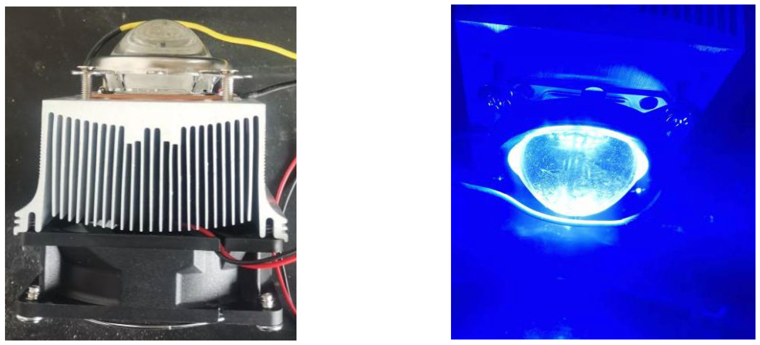
The choice of light-curing lamp should be based on the photosensitive wavelength of the photoinitiator. Existing curing lamps are mainly categorized as ultraviolet curing lamps, visible light-curing lamps, or infrared curing lamps. Visible light-curing lamps have certain differences in performance parameters according to different luminous principles, luminous intensity and use environment. The curing lamp is the main working part of light-curing equipment; curing lamps should have a long service life, long working time, high power, short curing time and other characteristics, and should output a stable and ideal band of light. The central wavelength of the CQ photosensitive band is 468 nm. In this study, an LED was selected as the light-curing lamp; LEDs are low priced, with a long lamp life (10,000~100,000 h), good stability, only a small amount of degradation of output power over time, and a light intensity of more than 1000 mW/cm
3, which can be improved by stacking the number of lights. LEDs have the advantages of simple operation, strong energy and low heat production, and are suitable for curing lamps. Additionally, for precise light-curing time, a time relay with two control channels was selected as the control device, and the time relay is shown in
Figure 3.
2.2. Reagents and Materials
When preparing visible light-curing slurry, we used Epoxy acrylic resin (EA); Polyurethane acrylic resin (PUA) as a prepolymer; pentaerythritol triacrylate (PETA); 1, 6-hexadiol diacrylate (HDDA); Hydroxypropyl acrylate (HPA) as an active diluted monomer; polyether modified polydimethyloxane (BYK-333); defoamer (BYK-A 530); and adhesion Promoter (HEMAP) as an additive.
The components of the energetic drug column include RDX; AP.
The solvents used in the experiment were anhydrous ethanol C2H5OH and shellac C6H9.6O1.6.
2.3. Preparation of Visible Light-Curing Slurry
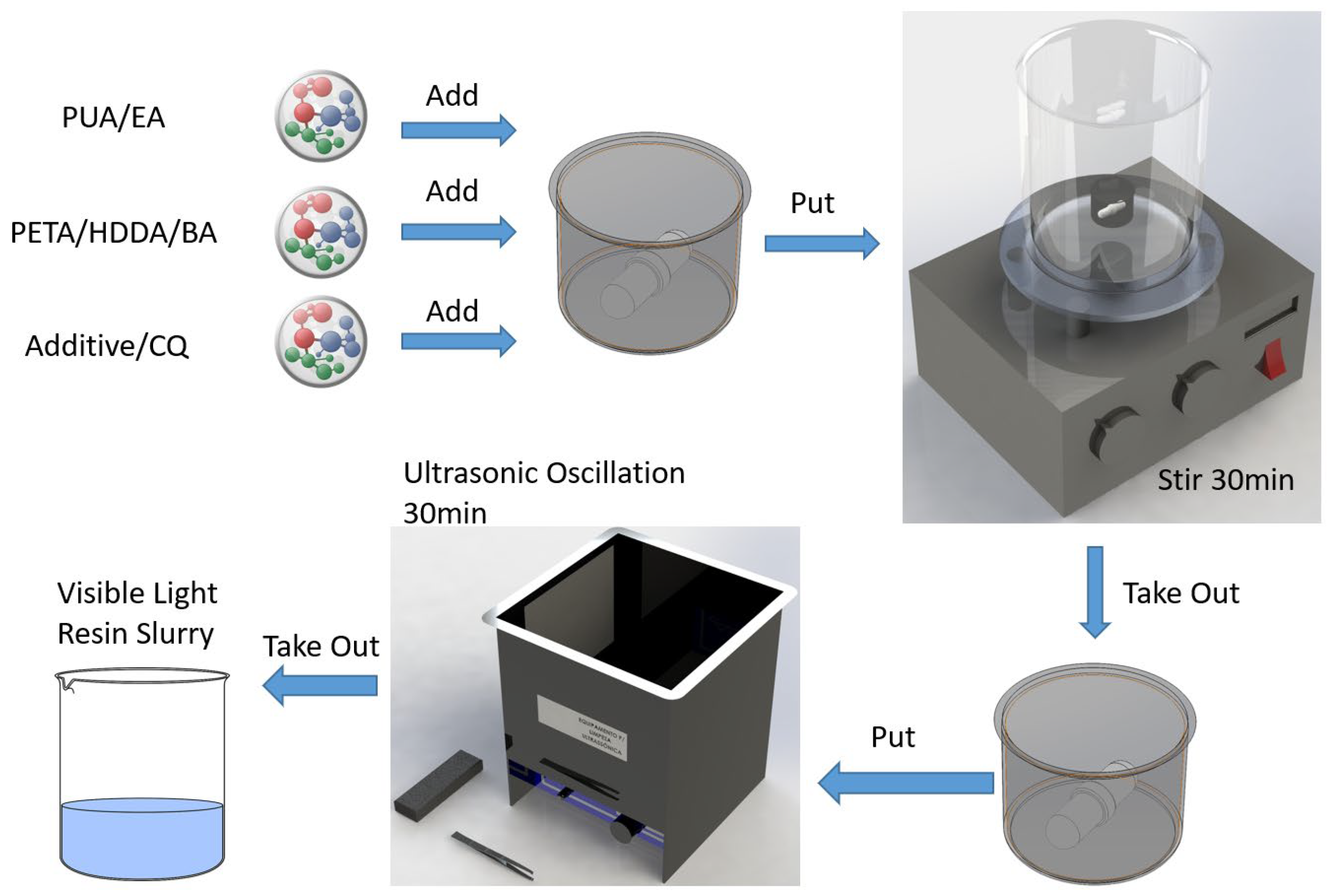
We carried out proportional weighing of quantitative EA/PUA, PETA/HDDA/BA, CQ, and placed them in the beaker. The rotor was added to the intelligent magnetic stirrer for mixing, and the beaker was sealed. The rotating speed was 510 rpm, the temperature was 30 °C, and the beaker was stirred for 30 min, so that the whole system was evenly mixed. The mixed solution was ultrasonic dispersed in the ultrasonic cleaning machine, and taken out after 30 min, and stored away from light for use. The preparation process of visible light-curing slurry is shown in
Figure 4.
2.4. Preparation of Energetic Power Column
By mixing RDX, AP, and Al powder with visible light-curing slurry, mixing for 1 h at a rotating speed of 500 r/min, and then dispersing under ultrasound for 5 min, energetic slurry was obtained. Benzene was selected as the inactive diluent of visible light-curing slurry, and 20% was determined as the solid content of energetic slurry. The energetic powder column formulation (mass fraction) was 9.57% RDX, 57.45% AP, 11.7% Al, and 21.28% visible light-curing slurry. The visible light-curing charging machine used G-code to control its operation. Each layer was transported 0.05 mL into the tube shell. The ultrasonic oscillation time was 30 s and the curing time was 120 s.
2.5. Material Characterization
- (1)
We judged whether the visible light-curing charging machine can operate normally and determined the best process parameters through flow rate test, single cantilever moving test, relay working test and light-curing lamp luminosity test.
- (2)
According to the “GB 1728-1979 paint film, putty film drying time determination method” we determined the visible light-curing paste surface drying time and actual drying time. We used NDJ-79 rotary viscometer to measure viscosity. We determined the hardness of visible light-curing paste concerning “GB/T 6739 2006 Pencil method for Determination of paint Film hardness of paint and varnish”.
- (3)
Using the PMS-XHD-AF optical microscope, the morphology of the energetic powder column was determined. The burning rate of energetic charge was measured by the target line method. The Ocean Fx fiber-optic spectrometer, Ocean Insight Instrument Co., Ltd. (Shanghai, China) was used to determine the combustion uniformity of the energetic power column. HX30 camera Sony Corporation. (Shanghai, China) was used to record the process of combustion effect and the combustion state at each period.
3. Results
3.1. Visible Light-Curing 3D Printing Platform Test
The visible light-curing 3D printing platform encompasses several modules: a light source, control, leveling, conveying, time relay, and heat dissipation. Upon assembly of all components, the completed visible light-curing 3D printing platform is depicted in
Figure 5.
We conducted tests on various components: the peristaltic pump, the three-axis stepper motor, the time relay, and the light-curing lamp. First, we carried out the peristaltic pump flow rate test. Second, we carried out the swing test on the single cantilever. Third, we observed whether the time relay provided the interrupt signal in time. Finally, the working state of the light-curing lamp was observed. Deionized water was introduced into the system through the funnel, and its flow was managed via the peristaltic pump and connected piping. The operational state of the pump is captured in
Figure 6. By executing the pre-set G-code, we monitored the movement of the single cantilever, illustrated in
Figure 7. Upon activation, the time relay was set to halt after 58 s; its functioning is demonstrated in
Figure 8. Lastly, when powered, the light-curing lamp emitted illumination as captured in
Figure 9.
In
Figure 6, the peristaltic pump effectively manages the deionized water from the funnel, providing a consistent and steady discharge, confirming its operational efficiency.
Figure 7 showcases the single cantilever moving exactly as pre-set, verifying its proper functionality. The time relay when activated, as depicted in
Figure 8, starts its countdown from 53 s, confirming its successful time management capability. Lastly, the regular light emission from the light-curing lamp, as seen in
Figure 9, attests to its optimal working condition. After the energetic slurry is added into the feeding funnel, the energetic slurry will flow along the pipe under the action of the peristaltic pump. At this time, the sprinkler head located on the X-axis pulley is controlled by the control motherboard. When the sprinkler head moves to the housing position, the computer software controls the peristaltic pump to put a certain amount of energetic slurry into the tube shell through extrusion. The first control channel of the time relay starts to control the work of the transducer, the transducer energizes the ultrasonic oscillator to generate ultrasound, and the ultrasound is transmitted to the slurry in the shell through the platform and the housing, so that the energetic slurry is smooth, the first control channel of the time relay cuts off the power, and the ultrasonic oscillator stops working. The second control channel of the time relay is activated, the control curing lamp provides enough visible light radiation to cure it, and the curing of a layer of energetic slurry is completed. Through the above process, the curing of the energetic slurry is completed layer by layer into the housing.
3.2. Study on the Formulation and Combustion Performance of Visible Light-Cured Slurry
The core ingredients of the visible light-curing paste comprised the prepolymer, active diluent monomer, photoinitiator, and various additives. The prepolymer was EA/PUA, the active diluted monomer was PETA/HDDA/BA, and the photoinitiator selected was camphorone (CQ), augmented with dimethyl terephthalate (DMT) as the active agent. The additives encompassed the leveling agent BYK-333, the defoamer BYK-A530, and the adhesion accelerator HEMAP [
14,
15]. The curing time
t, curing hardness
H, and curing depth
h are the important indexes used to evaluate the performance of the photocuring paste: EA/PUA ratio (A), the active diluent–monomer blend of PETA/HDDA/BA (B), the photoinitiator CQ’s concentration (C), and the quality of the additive (D). Orthogonal experiments helped determine the optimal formula.
Table 1 shows the quality represented by the four levels, while
Table 2 represents the result of orthogonal test.
As shown in
Table 1 and
Table 2, the curing time, curing hardness and curing depth were analyzed using the range analysis method. The curing time of visible light-curing pastes is less than 12.1 s, and the main factor affecting the curing time is the content of CQ (C). The factor that had the greatest influence on the curing hardness was the active diluent monomer (B). CQ (C) was the most important factor affecting the curing depth. Each factor affected the main order from the largest to the smallest for curing depth, curing time, curing hardness. Therefore, A
4#B
3#C
1#D
2# was selected as the best formula, and its mass fraction is shown in
Table 3. Its viscosity, curing hardness, curing time, and other performance parameters are shown in
Table 4.
The properties of visible light-cured paste are shown in
Table 4. The curing time is 7.5 s, the viscosity is 226 mPa·s, the curing hardness is 2 H, the gel rate is 96.67%, the shrinkage rate is 98.35%, and the curing depth is 9.41 mm.
3.3. Formulation and Morphology Analysis of Energetic Power Column
To produce the energetic paste, solid filler was combined with the visible light-curing paste. This mixture was stirred for 1 h at a rotation speed of 500 r/min, followed by 5 min of ultrasonic dispersion. Various visible light-curing pastes, with solid contents of 85%, 80%, 75%, and 70%, were prepared and assessed.
Table 5 showcases the results to determine the formation consistency of these pastes.
Table 5 reveals that with a solid content of 85%, the energetic slurry remains unformed. However, at 80% solid content, it takes shape. Therefore, 80% was chosen as the ideal solid content for the energetic slurry. Using the standard deviation as the assessment metric [
16,
17], the preparation of the energetic drug column considered four primary factors: the quality of RDX (A), AP (B), Al (C), and the visible light-solidified slurry (D). An analysis based on orthogonal experiments helped determine the best formula [
18,
19]. Details of these orthogonal factor levels are presented in
Table 6, while
Table 7 displays the standard deviations derived from the orthogonal test results.
It can be seen from
Table 7, with the standard deviation as the evaluation index, the order of influence of the four factors is visible light-solidified slurry > RDX > AP > Al, and the R value of visible light-solidified slurry is 0.11, which has the greatest influence; that is, A
3B
1C
1D
2 is the optimal energetic slurry formula. A 20% solid content was established for the energetic slurry. The composition of this slurry includes 9.57% RDX, 57.45% AP, 11.7% Al, and 21.28% of the visible light-curing slurry. The slurry cures in 30.5 s, with a curing depth of 2.3 mm and a hardness rated at HB.
Figure 10 provides a visual of the energetic paste. The casing measures Φ6 mm × 6 mm with a wall thickness of 0.5 mm. Post-charging, the energetic power within the shell retains the size of Φ6 mm × 6 mm. This charged energetic column within the shell is depicted in
Figure 11.
To explore the difference between 3D printing and traditional pressure loading by using the PMS-XHD-AF optical microscope, the energetic power column made by the visible light-curing charge mechanism and the power column made using the pressing charge method were observed. The microscopic picture of the pressing power column is shown in
Figure 12a. The microscopic diagram of the 3D-printed energetic power column is shown in
Figure 12b.
As shown in
Figure 12a, there are structural defects such as obvious cracks and holes on the surface of the pressure power column, and the particle distribution is uneven. As shown in
Figure 12b, the surface of the energetic power column is smooth, the packing is evenly distributed, the surface is flat, and there are no defects such as protrusions, which can ensure the combustion performance of the power column.
3.4. Calculation of Burning Rate of Energetic Charge
The mass burning velocity of energetic powder column was measured using the target line method. The linear burning rate can be calculated by the Formula (1).
where
v denotes the 3D-printed powder column linear burning rate, mm‧s
−1;
h refers to the distance between two target lines, mm; and
t stands for burn time.
The burning time of the energetic power column was recorded using an oscilloscope. The CH1 channel and CH2 channel of the oscilloscope are connected at both ends of the energetic power column, respectively, and the energetic power column is detonated by a detonator. The CH1 channel voltage of the oscilloscope changes when the powder column burns to target line 1, and the CH2 channel voltage changes when it burns to target line 2. The burning time of the powder column is obtained by observing the distance between the CH1 signal and the CH2 signal of the oscilloscope. The burning time of the energetic powder column is recorded using the oscilloscope, as shown in
Figure 13. The burning rate and standard deviation of the energetic power column are shown in
Table 8.
As shown in
Table 8, according to formula 1, the length of the energetic power column is 6 mm, the average burning rate is 1.165 mm·s
−1, and the standard deviation is 0.0283 mm·s
−1. The difference in burning rate between power columns is not large, and the residue rate is small. The largest residue ratio, belonging to energetic power column 3#, is only 2.988%.
The visible light-curing charge machine was used to charge the energetic slurry with a solid content of 80%. The cylindrical power column with a size of Φ6 mm × 6 mm was formed and ignited, and the combustion status of the energetic power column was observed and analyzed. The combustion effect of the energetic power column photographed with the camera shoot at a distance of 10 cm is shown in
Figure 14.
Figure 14 illustrates the combustion progression of the energetic propellant column and its state at various intervals. Between 1 s and 2 s, the power column ignites, producing a luminous yellow flame that projects uniformly in a specific direction. From 2 s to 4.5 s, the flame elongates, maintaining a stable combustion with a clear interface, and there is no emission of black smoke. As it transitions from 4.5 s to 5 s, the flame starts to diminish until the burn concludes. Throughout this process, the powder column exhibits consistent burning. The flame’s elongation, followed by its reduction, suggests the complete reaction of the energetic powder column components and the high dispersion of the solid filler within the energetic slurry. The entire combustion is marked by a radiant flame, devoid of black smoke, and showcases parallel layer burning, producing a consistent yellow flame.
The luminosity resulting from the energetic power column’s combustion can be perceived as a point light source. This is directed towards the visible light detector’s probe and is kept at a fixed distance. As the combustion ensues, its optical effect is captured by the detector probe and relayed to OPT2000. This feedback allows for the charting of the combustion’s luminous intensity over time, which in turn helps ascertain the consistency of the energetic power column’s burn. These findings are visually represented in
Figure 15.
In
Figure 15, it is evident that upon ignition, the energetic powder column’s combustion rapidly intensifies within the first 0.5 s, achieving its peak luminous intensity. This intensity stabilizes around 202.2 lx, with a peak value reaching up to 205.3 lx. This means that the light intensity is 2.053 cd. However, after the 4.5-s mark, there is a gradual decline in light intensity until it ceases entirely, signaling the end of combustion. Such a pattern reflects the relative stability and sustainability of the powder column’s combustion.
4. Discussion
A visible light-curing 3D printing machine has been developed, comprising a control device, conveying apparatus, leveling mechanism, and a light source module. The control system is an integration of the Mks-Robin control board, the Marlin 2.0 control system, and the Simplify3D software, orchestrating the operations of the leveling and light source devices as well as the conveying mechanism. The conveying apparatus, built around the BJ 1030-4 peristaltic pump and its feed pipeline, ensures the precise transportation of energetic slurry. The leveling mechanism employs a transducer and an ultrasonic oscillator to ensure the uniform distribution of the energetic slurry within the tube shell. Lastly, the light source module, featuring a cooling fan and a 50 W visible light-curing lamp, facilitates the curing of the energetic slurry contained within the shell. This design introduces a groundbreaking 3D printing charging method that boasts zero pollution, no radiation, and heightened safety.
Through orthogonal experimentation and range analysis, with the curing depth as the evaluation index, the best formulations for the visible light-curing slurry were EA/PUA (prepolymer), 37.21% PETA/HDDA/BA (active diluent monomer), 0.47% CQ (visible light initiator), 0.93% DMT (active agent), and an additional 0.93% of other additives. Using standard deviation as the evaluation index, the optimal formulation of the energetic power column was 20% visible light-curing slurry, 57.72% AP, 15.28% Al, and 7% RDX. The experimental results show that the section of the energetic powder column was smooth, the packing was evenly distributed, and it had good compatibility. The average combustion rate of the energetic propellant column was 1.165 mm·s−1; the maximum light intensity during the combustion of the charge column was 2.053 cd. This novel light-curing 3D printing platform provides a new way for charging the energetic charge column.
Author Contributions
Conceptualization, Y.F. and S.B.; methodology, S.B.; software, Y.F.; validation, Y.F., B.Z. and L.L.; formal analysis, Y.Y.; investigation, Y.F.; resources, Y.F.; data curation, B.Z.; writing—original draft preparation, Y.F.; writing—review and editing, Y.F.; visualization, S.B.; supervision, S.B.; project administration, S.B. All authors have read and agreed to the published version of the manuscript.
Funding
This research received no external funding.
Institutional Review Board Statement
Not applicable.
Informed Consent Statement
Not applicable.
Data Availability Statement
Not applicable.
Conflicts of Interest
The authors declare no conflict of interest.
References
- Degges, M.J.; Taraschi, P.; Syphers, J.; Armold, D.; Boyer, J.E.; Kuo, K. Student investigation of rapid prototyping technology for hybrid rocket motor fuel grains. In Proceedings of the 49th AIAA/ASME/SAE/ASEE Joint Propulsion Conference, San Jose, CA, USA, 14–17 July 2013; American Institute of Aeronautics and Astronautics: Atlanta, GA, USA, 2013; Volume 15, p. 2337. [Google Scholar]
- Primera-Pedrozo, O.M.; Pacheco-Londoño, L.; Ruiz, O.; Ramirez, M.; Hernández-Rivera, S.P.; Briano, J. Spectroscopic characterization of thermal inkjet transfer of deposits of energetic materials. In Proceedings of the Third LACCEI International Latin American and Caribbean Conference for Engineering and Technology, Boca Raton, FL, USA, 8–10 June 2005. [Google Scholar]
- Michael, V. Nist program to support T&E of trace explosives detection. ITEA J. 2007, 9, 16. [Google Scholar]
- Kuo, S.M.; Yang, C.C.; Shiea, J.; Lin, C.H. A post-bonding-free fabrication of integrated microfluidic devices for mass spectrometry applications science direct. Sens. Actuators B Chem. 2011, 156, 156–161. [Google Scholar] [CrossRef]
- Amy, D. Explosive Ink Formulation for the Loading of MEMS; NDIA: Baltimore, MD, USA, 2006; Volume 91, p. 122. [Google Scholar]
- Fuchs, B.E. Direct Write Explosive Ink Formulations; NDIA: Baltimore, MD, USA, 2007; Volume 92, p. 176. [Google Scholar]
- Fuchs, B.E.; Wilson, A.; Cook, P.; Stec, D., III. Development, performance and use of direct write explosive inks. In Proceedings of the 14th International Detonation Symposium—IDS, Coeur d’Alene, ID, USA, 11–16 April 2010; p. 283. [Google Scholar]
- Windsor, E.; Najarro, M.; Bloom, A.; Benner, B.; Fletcher, R.; Lareau, R.; Gillen, G. Application of inkjet printing technology to produce test materials of 1,3,5-trinitro-1,3,5 triazcyclohexane for trace explosive analysis. Anal. Chem. 2010, 82, 8519. [Google Scholar] [CrossRef]
- Ihnen, A.; Fuchs, B.; Petrock, A.; Samuels, P.; Stepanov, V.; Di Stasio, A.; Lee, W. Inkjet printing of nanocomposite high explosive materials. In Proceedings of the 14th International Detonation Symposium, Coeur d’Alene, ID, USA, 11–16 April 2010; p. 126. [Google Scholar]
- Ihnen, A.C.; Petrock, A.M.; Chou, T.; Samuels, P.J.; Fuchs, B.E.; Lee, W.Y. Crystal morphology variation in inkjet-printed organic materials. Appl. Surf. Sci. 2011, 258, 827–833. [Google Scholar] [CrossRef]
- Wang, D.; Zheng, B.; Guo, C.; Gao, B.; Wang, J.; Yang, G.; Huang, H.; Nie, F. Formulation and performance of functional submicro CL-20-based energetic polymer composite ink for direct-write assembly. RSC Adv. 2016, 6, 112325. [Google Scholar] [CrossRef]
- Wang, H.; Shen, J.; Kline, D.J.; Eckman, N.; Agrawal, N.R.; Wu, T.; Wang, P.; Zachariah, M.R. Direct Writing of a 90 wt% Particle Loading Nanothermite. Adv. Mater. 2019, 31, 1806575. [Google Scholar] [CrossRef] [PubMed]
- Park, H.K.; Shin, M.; Kim, B.; Park, J.W.; Lee, H. A visible light-curable yet visible wavelength-transparent resin for stereolithography 3D printing. NPG Asia Mater. 2018, 10, 82–89. [Google Scholar] [CrossRef]
- Armold, D.; Boyer, J.E.; Kuo, K.; Fuller, J.K.; Desain, J.; Curtiss, T.J. Test of hybrid rocket fuel grains with swirl patterns fabricated using rapid prototyping technology. In Proceedings of the 49th AIAA/ASME/SAE/ASEE Joint Propulsion Conference, San Jose, CA, USA, 14–17 July 2013; American institute of Aeronautics and Astronautics: Atlanta, GA, USA, 2013; Volume 17, p. 2346. [Google Scholar]
- Ba, S.-h.; Yang, Y.-l.; Shen, H.-q.; Wang, S.-t.; Sun, W.-d. Delay Property of Energetic Grain via Digital Light Processing Photocurable 3D Printing. Chin. J. Energ. Mater. 2022, 30, 363. [Google Scholar]
- Brousseau, P.; Anderson, C.J. Nanometric Aluminum in Explosives. Propellants Explos. Pyrotech. 2002, 27, 300–306. [Google Scholar] [CrossRef]
- Eisenreich, N.; Fietzek, H.; Juez-Lorenzo, M.d.M.; Kolarik, V.; Koleczko, A.; Weiser, V. On the mechanism of low temperature oxidation for aluminum particles down to the nanoscale. Propellants Explos. Pyrotech. 2004, 29, 137–145. [Google Scholar] [CrossRef]
- We, Y.; Wan, J.; An, C.; Li, H. Curing reaction and rheological properties of a slurry of htpb/cl-20-based composite explosive. Int. J. Energ. Mater. Chem. Propuls. 2015, 5, 437. [Google Scholar] [CrossRef]
- Muravyev, N.V.; Monogarov, K.A.; Schaller, U.; Fomenkov, I.V.; Pivkina, A.N. Progress in Additive Manufacturing of Energetic Materials: Creating the Reactive Microstructures with High Potential of Applications. Propellants Explos. Pyrotech. 2019, 44, 941–969. [Google Scholar] [CrossRef]
Figure 1.
Process flow chart.
Figure 1.
Process flow chart.
Figure 2.
Ruhr inner and outer rotating joints.
Figure 2.
Ruhr inner and outer rotating joints.
Figure 4.
Visible light-curing slurry preparation process.
Figure 4.
Visible light-curing slurry preparation process.
Figure 5.
Visible light-curing 3D printing platform.
Figure 5.
Visible light-curing 3D printing platform.
Figure 6.
Peristaltic pump text.
Figure 6.
Peristaltic pump text.
Figure 7.
Single cantilever swing test.
Figure 7.
Single cantilever swing test.
Figure 8.
Time relay test.
Figure 8.
Time relay test.
Figure 9.
Working test of light-curing lamp.
Figure 9.
Working test of light-curing lamp.
Figure 10.
Energetic slurry.
Figure 10.
Energetic slurry.
Figure 11.
Energetic cylinders printed in metal tubes.
Figure 11.
Energetic cylinders printed in metal tubes.
Figure 12.
Microstructure of energetic power column (a) Traditional pressure power column structure defects; (b) 3D printing of power column structure.
Figure 12.
Microstructure of energetic power column (a) Traditional pressure power column structure defects; (b) 3D printing of power column structure.
Figure 13.
Burning rate test oscilloscope waveform diagram.
Figure 13.
Burning rate test oscilloscope waveform diagram.
Figure 14.
Combustion state diagram of energetic drug column (a) 0 s; (b) 0.5 s; (c) 1 s; (d) 1.5 s; (e) 2 s; (f) 2.5 s; (g) 3 s; (h) 3.5 s; (i) 4 s; (j) 4.5 s; (k) 5 s.
Figure 14.
Combustion state diagram of energetic drug column (a) 0 s; (b) 0.5 s; (c) 1 s; (d) 1.5 s; (e) 2 s; (f) 2.5 s; (g) 3 s; (h) 3.5 s; (i) 4 s; (j) 4.5 s; (k) 5 s.
Figure 15.
Relationship between burning light intensity and time of energetic powder column.
Figure 15.
Relationship between burning light intensity and time of energetic powder column.
Table 1.
Orthogonal test factor level table.
Table 1.
Orthogonal test factor level table.
| | A (g) | B (g) | C (g) | D (g) |
|---|
| Level 1# | 5.0 | 5.0 | 0.05 | 0.05 |
| Level 2# | 5.5 | 4.5 | 0.10 | 0.10 |
| Level 3# | 6.0 | 4.0 | 0.15 | 0.15 |
| Level 4# | 6.5 | 3.5 | 0.20 | 0.20 |
Table 2.
Experimental results of orthogonal test.
Table 2.
Experimental results of orthogonal test.
| A | B | C | D | t (s) | H | h (mm) |
|---|
| 2# | 4# | 3# | 2# | 7.4 | 5 | 6.67 |
| 4# | 3# | 2# | 4# | 5.9 | 3 | 12 |
| 1# | 4# | 4# | 4# | 9.1 | 6 | 6 |
| 2# | 2# | 1# | 4# | 6.1 | 2 | 13 |
| 4# | 1# | 4# | 2# | 6.0 | 5 | 8 |
| 1# | 2# | 2# | 2# | 4.1 | 4 | 13 |
| 1# | 3# | 3# | 3# | 6.8 | 10 | 6.5 |
| 3# | 4# | 2# | 1# | 7.5 | 3 | 11 |
| 3# | 3# | 1# | 2# | 7.0 | 10 | 17 |
| 4# | 4# | 1# | 3# | 6.5 | 6 | 12 |
| 2# | 3# | 4# | 1# | 10.1 | 3 | 4 |
| 2# | 1# | 2# | 3# | 7.9 | 1 | 10 |
| 4# | 2# | 3# | 1# | 6.5 | 8 | 11 |
| 3# | 2# | 4# | 3# | 12.1 | 5 | 6 |
| 1# | 1# | 1# | 1# | 8.9 | 1 | 23 |
| 3# | 1# | 3# | 4# | 6.9 | 3 | 16 |
Table 3.
Best formula of visible light-curing slurry.
Table 3.
Best formula of visible light-curing slurry.
| Name | Mass Fraction (%) |
|---|
| EA/PUA (2:1) | 60.46 |
| PETA/HDDA/BA (1:1:1) | 37.21 |
| CQ | 0.47 |
| DMT | 0.93 |
| Additive | 0.93 |
Table 4.
Visible light-curing paste formula performance parameters.
Table 4.
Visible light-curing paste formula performance parameters.
| Name | Value |
|---|
| Curing tim (s) | 7.5 |
| Viscosity (mPa·s) | 226 |
| Curing hardness (H) | 2 |
| Gel ratio (%) | 96.67 |
| Percentage of contraction (%) | 98.35 |
| Curing depth (mm) | 9.41 |
Table 5.
Curing degree of energetic slurry with different solid content.
Table 5.
Curing degree of energetic slurry with different solid content.
| Solid Content | Molding Degree |
|---|
| 70% | Successful |
| 75% | Successful |
| 80% | Successful |
| 85% | Failed |
Table 6.
Level table of factors for orthogonal test of energetic slurry.
Table 6.
Level table of factors for orthogonal test of energetic slurry.
| | A (g) | B (g) | C (g) | D (g) |
|---|
| Level 1# | 5 | 54 | 11 | 18 |
| Level 2# | 7 | 57 | 13 | 20 |
| Level 3# | 9 | 60 | 15 | 22 |
Table 7.
Orthogonal design standard deviation results.
Table 7.
Orthogonal design standard deviation results.
| | A | B | C | D | Standard Deviation (s) |
|---|
| 1 | 1# | 1# | 1# | 1# | 0.120 |
| 2 | 1# | 2# | 2# | 2# | 0.220 |
| 3 | 1# | 3# | 3# | 3# | 0.317 |
| 4 | 2# | 1# | 2# | 3# | 0.180 |
| 5 | 2# | 2# | 3# | 1# | 0.108 |
| 6 | 2# | 3# | 1# | 2# | 0.085 |
| 7 | 3# | 1# | 3# | 2# | 0.031 |
| 8 | 3# | 2# | 1# | 3# | 0.169 |
| 9 | 3# | 3# | 2# | 1# | 0.159 |
| R | 0.099 | 0.077 | 0.063 | 0.11 | |
Table 8.
Combustion performance of energetic powder column.
Table 8.
Combustion performance of energetic powder column.
| | Length | Burning Time | Burning Rate | Average Burning Rate | Standard Deviation | Residue Ratio |
|---|
| (mm) | (s) | (mm·s−1) | (mm·s−1) | (mm·s−1) | (%) |
|---|
| 1# | 6 | 5.13 | 1.169 | 1.165 | 0.0283 | 2.912 |
| 2# | 6 | 5.32 | 1.128 | 3.012 |
| 3# | 6 | 5.01 | 1.197 | 2.988 |
| Disclaimer/Publisher’s Note: The statements, opinions and data contained in all publications are solely those of the individual author(s) and contributor(s) and not of MDPI and/or the editor(s). MDPI and/or the editor(s) disclaim responsibility for any injury to people or property resulting from any ideas, methods, instructions or products referred to in the content. |
© 2023 by the authors. Licensee MDPI, Basel, Switzerland. This article is an open access article distributed under the terms and conditions of the Creative Commons Attribution (CC BY) license (https://creativecommons.org/licenses/by/4.0/).


