1. Introduction
With the vigorous development of China’s economy and the dynamic implementation of urbanization, high-rise, and super-high-rise buildings are growing up. According to the statistics of the Council on Tall Buildings and Urban Habitat (CTBUH), by the end of 2022, there are 11 of the world’s top 20 skyscrapers in China, and Shanghai Tower, with a total height of 632 m, ranks the second in the list [
1]. In high-rise and ultra-high-rise buildings, conventional elevators often operate at slow speeds, resulting in low transportation efficiency. This has prompted elevators to evolve for higher speeds and greater comfort. At present, the high-speed elevators used in Shanghai Tower have reached 18 m/s. The increase in speed of these elevators meets the vertical transportation needs of high-rise buildings and improves traffic efficiency. However, along with the speed upgrade, there are some negative effects. For example, high-speed elevators experience greater wear and tear on their components during operation, which requires higher wear resistance and strength of structural materials. The higher running speed of the elevators results in more noticeable vibrations and makes them more susceptible to external stimuli, leading to abnormal vibrations that affect ride comfort [
2,
3]. Previous research has shown that slight vibration generally will not affect the safety and health of passengers. However, when the amplitude reaches a certain value, it will trigger the resonance phenomenon of the organs of passengers, which results in irreversible damage to their health [
4]. Additionally, the human body has a sensitive range for cabin vibrations, which is 4–8 Hz vertically and 1–2 Hz horizontally with a higher sensitivity [
5]. Vibration control, as one of the core technologies of high-speed elevators, directly influences the comfort of elevator rides and is also an important criterion for evaluating the quality of high-speed elevators. With the large scale of existing high-speed elevators and demanding requirements for safety and comfort, effective control of lateral vibrations in elevator cars holds great engineering significance for improving the quality of elevator rides.
The lateral vibration control of the car can be divided into three main methods: passive control, active control, and hybrid control. Among them, passive control consumes the least energy but can only target vibrations within a narrow frequency band, making it less suitable for dynamic high-speed elevator parameters [
6]. On the contrary, active control provides the best results but consumes the most energy. Hybrid control considers the coupling relationships between high-speed elevator structural parameters and active control, achieving a balance between power consumption and vibration reduction effectiveness.
Presently, there are few studies on the lateral vibration of high-speed elevator cars. Nakano [
7] et al. designed a new type of damping element consisting of two rotating motors and an eccentric disc. Experimental results show that the dampers can reduce lateral vibrations, but their actual effect depends on the accuracy of the manufacture and installation of the components. Liu [
8] et al. established a model for the horizontal vibration dynamics of high-speed elevator cars by considering the relationship between lateral forces and overturning moments and horizontal displacement, deflection angle displacement, and rated speed. Utsunomiya [
9] et al. analyzed the vibration spectrum of the guide rail, which indicated that the disturbance of the rail mainly concentrated in the low-frequency areas, and there was a main disturbance frequency which was directly proportional to the running speed of the elevator and inversely proportional to the guide-rail length. Colón [
10] et al. used the Karhunen–Loève Transform and polynomial chaos method to study the dynamic characteristics and control means of the horizontal vibration of elevator car caused by rail irregularity through the establishment of the irregular stochastic model of the rail profile. Santo [
11] et al. investigated the horizontal vibration response due to guideway roughness in a three-degree-of-freedom lift vertical motion model and proposed a control strategy based on the state-dependent Riccati equation. Zhang [
12] et al. designed a BPNN-PID controller with a linear predictive model using linear motors as actuators for the intelligent control of car vibration under uncertain external excitation. Wang [
13] et al. proposed a semi-active damping method based on a Particle Swarm Optimization (PSO) algorithm to control the adjustable damper of magneto-rheological fluid. In the aforementioned research on lateral vibration control of elevators, most of the research methods have only remained in the experimental stage and have not been applied to actual elevators. Moreover, all the studies have shown insignificant control effects on the lateral vibration of the car. That is, they have not reduced the resonance amplitude of the human body within the sensitive frequency range.
Most of the vibrations in high-speed elevators are caused by the unevenness of the guide rails. In order to reduce the impact of the guide rails, the car is “suspended” on them. The electromagnetic active rolling guide shoes can exert active control force through electromagnetic force, which can separate the car from the guide rails and reduce the impact of the uneven guide rails on the car [
14]. This structure can also be easily added to the traditional guide shoes of the elevator. The electromagnetic active rolling guide shoes can be regarded as a traditional damper between the car and the guide rails. Traditional dampers have the disadvantage of increasing vibration when the absolute speed and relative speed are opposite, while the sky-hook damping control strategy can effectively compensate for that [
15,
16]. Therefore, this paper adds electromagnetic active rolling guide shoes to the structure of high-speed elevators and introduces the sky-hook damping control strategy. In the strategy, many important parameters related to vibration reduction need to be adjusted. However, manually determining a set of optimal parameters to effectively suppress car vibration requires a large amount of difficult calculation. Optimization algorithms can solve the problem of seeking the optimal solution for multiple parameters. Sparrow Search Algorithm (SSA) is a new intelligent optimization algorithm proposed by Xue [
17] et al. in 2020 based on the foraging and anti-predation behavior of sparrows. Compared with other swarm intelligence optimization algorithms, SSA has the advantages of strong optimization ability, fast convergence speed, strong robustness, and stable performance. Therefore, this paper proposes a lateral vibration control strategy based on SSA for the lateral vibration of the high-speed elevator cabin within the human-sensitive frequency range. Through Simulink numerical simulation research and analysis of experimental results, it is demonstrated that the method proposed in this paper can effectively reduce the lateral vibration of high-speed elevators within the human-sensitive frequency range and improve the ride quality of high-speed elevators.
The remaining sections of this paper are arranged as follows: In
Section 2, a mathematical model for car vibration is established based on the structure and vibration modes of high-speed elevators. The control equation for sky-hook damping is also introduced in this section. In
Section 3, the SSA is presented. In
Section 4, a Simulink simulation model is built based on the mathematical model in
Section 2, and simulations are performed using the model. In
Section 5, the specific structural parameters obtained through the optimization algorithm are applied to an actual high-speed elevator for verification.
Section 6 concludes the paper.
2. High-Speed Elevator Car Vibration Model and Sky-Hook Damping Control Strategy
The guiding system of a high-speed elevator is composed of guide shoes and guide rails, and the guide shoe structure has a great impact on the lateral vibration of the elevator car [
18]. Compared with traditional guide shoes, electromagnetic active sliding guide shoes, and electromagnetic active rolling guide shoes have better vibration reduction performance. The electromagnetic active sliding guide shoes form a gap between the guide shoes and the guide rails through the electromagnetic force. Thus, the car is suspended on the guide rails so as to effectively reduce the lateral vibration of the high-speed elevator. However, it requires high control technology and reliability [
19]. Therefore, it is not widely used in practice. Electromagnetic active rolling guide shoes use an electromagnet to exert active control force on the basis of rolling guide shoes. Its structural diagram is shown in
Figure 1. Since this structure has little change to the original high-speed elevator, it owns a wider range of applications. The introduction of electromagnetic active rolling guide shoes in the vibration control of high-speed elevators aims to convert the damping related to car vibration into an adjustable one.
In order to effectively reduce the vibration of the elevator car, the electromagnetic active rolling guide shoe structure is introduced. Inspired by the sky-hook damping control strategy in high-speed train cabin vibration control, the strategy is also introduced into the vibration control of high-speed elevators.
The sky-hook damping control method compensates for the shortcomings of traditional dampers in that the damping force generated by the damper increases the vibration of the car when the car’s motion speed and relative speed (between the car and the frame) are opposite. The strategy of sky-hook damping control is to make the damping force of the damper zero or reduce it to a minimum when the car’s motion speed and the relative speed between the car and the frame are different, thereby reducing the vibration of the car in the above-mentioned situation. The calculation for the sky-hook damping control is shown as Formula (1).
where
and
respectively denote the horizontal speed and frame of the elevator car, and
represents the damping coefficient of transverse shock absorber.
In practice, the relative speed between the car and the car frame may be zero or a minimum. According to Formula (1), in such cases, the value of
will tends to infinity, exceeding the maximum value of the actual adjustable damper and damping coefficient. Since the damping force that can be generated by the actual shock absorber has a range, it can only approximately achieve some characteristics of the ideal sky-hook damper. Therefore, the values of
and
are set in this case. The actual application of sky-hook damping control in lateral vibration control of high-speed elevators is represented by Formula (2).
The high-speed elevator car system consists of three parts, namely, the car frame, the car, and the vibration-damping rubber block at the bottom. In order to establish a mathematical model for the lateral vibration of the elevator car in a high-speed elevator, the vibration-damping rubber blocks in the car system and the rolling guide shoes in the guiding system are simplified as a spring-damping system, while the other parts can be considered as rigid bodies. By simplification, a schematic diagram of the simplified structure of the elevator car and guiding system in a high-speed elevator can be obtained, as shown in
Figure 2.
According to the theory of dynamics, a mathematical model for lateral vibration of a high-speed elevator with four degrees of freedom, considering the separation of the car frame and the car, and the upper and lower guide shoes, is established. Formulas (3)–(5) correspond to the translational, pitch, and roll motion modes shown in
Figure 2.
where
,
,
and
represent the horizontal displacements of the four guide shoe wheels.
The lateral vibration simulation model of a high-speed elevator car can be obtained by synthetically establishing the equations of the three motion modes. Different motion modes involve different motion equations as follows [
20]:
In the case of translational motion, the motion equation of the high-speed elevator car frame is shown in Formula (6):
The car motion equation of a high-speed elevator is shown in Formula (7):
where
is the mass of the car frame,
is the displacement of the mass center of the car frame,
is the mass of the car,
is the displacement of the car,
is the lateral stiffness coefficient of the vibration-damping rubber block at the car bottom,
is the damping coefficient of the vibration damping rubber block,
is the stiffness coefficient of the rolling guide shoes, and
is the damping coefficient of the rolling guide shoes.
When pitching, the motion equation of the high-speed elevator car frame is drawn in Formula (8).
The motion equation of a high-speed elevator car is shown in Formulas (9)–(11):
where
to
are the dimensions of the high-speed elevator car,
is the car rotational inertia under the mode,
is the car frame rotational inertia under the mode,
is the car angle, and
is the car frame angle.
When doing Roll motion, the motion equation of the high-speed elevator car frame is drawn in Formula (12):
The motion equation of the high-speed elevator car is shown in Formula (13):
where
is the moment of inertia of the car,
is the moment of inertia of the car frame,
is the corner of the car, and
is the corner of the car frame.
In the established mathematical model of the high-speed elevator, the inclusion of the electromagnetic active rolling guide shoes allows the damping of the guide shoes to be controllable in the three modes of motion with lateral vibration. In lateral vibration control, these three damping parameters are crucial. Manual adjustment of these damping parameters and the values of the damping boundaries in the sky-hook damping control strategy cannot satisfy the requirement of minimizing vibration. Therefore, an optimization algorithm is needed to adjust these three damping parameters and the values of and in the sky-hook damping control strategy.
3. Optimization of Lateral Vibration Parameters Based on the SSA
In order to address the optimization of vibration control parameters within the range of human sensitivity in high-speed elevators, the optimization algorithm of SSA is employed. The objective function is defined as the minimum mean value of vibration amplitude within the frequency range of 1–2 Hz. Through iterative calculations, the optimization process aims to find the optimal values for the three damping parameters of the electromagnetic active rolling guide shoes and the parameters and in the sky-hook damping control strategy for minimizing vibrations. In this algorithm, the fitness of each generation of the sparrow population is continuously calculated during the iteration process, and then the parameters are fed back and adjusted to make the sparrows in the population move toward the global optimal value and quickly converge near the value. Specifically, it is divided into the following steps:
First, the sparrow population is constructed according to Formula (14):
where
d represents the parameter dimension to be optimized, and
n denotes the number of sparrow populations.
The fitness function is considered to obtain the fitness matrix of the sparrow population, as shown in Formula (15):
where
F represents the sparrow population fitness matrix, and
f denotes the fitness function.
The sparrows in the SSA population are mainly divided into three categories: the discoverer, the follower, and the vigilante. The discoverer is responsible for searching for areas with rich food, which has better adaptability. It can provide the follower with the areas and directions for foraging. The follower searches for food simultaneously. The watcher takes the responsibility for observing whether there exist predators around or not. The discoverer owns a larger foraging search range, and the identities of the discoverer and the follower will be dynamically updated. When the follower finds a better food source, it will turn its identity to the discoverer.
Under normal circumstances, the discoverer prioritizes obtaining food based on the higher adaptability when searching for food. Furthermore, the positions of these successful sparrows are updated after each iteration. The position-updated formula of the discoverer is shown in the following:
where
represents the position of a sparrow,
represents the current iteration number,
represents the maximum number of iterations,
represents a random number within the interval
,
represents the danger value, which ranges within the interval
, and
expresses the safety value, which also ranges between within the interval
,
is a random number subject to normal distribution.
represents a
matrix in which all elements are 1.
If the watcher finds a predator in the foraging environment, an alarm signal will be sent. When the danger value is greater than the safety value, the discoverer will take the follower to other safe areas for foraging. For the watcher,
DG < ST manifests that the danger value is lower than the safety value. In other words, it means that there is no predator, and the discoverer can continue searching. If
DG ≥ ST, it indicates that the watcher has found the predator, and all sparrows should leave the area for other safe places. The initial position of the watcher is randomly generated in the population, and the position expression is shown in Formula (17):
where
denotes the current global optimal location, indicating that the food source here is the most abundant and the population is also the safest.
is a random number subject to a normal distribution with a mean value of 0 and a variance of 1, which is used here as the step control parameter and the direction of sparrow movement.
is a random number.
is a non-zero constant, which is used to avoid the case where the denominator is zero.
is the fitness value of the current individual sparrow.
and
are the current global best and worst fitness values, respectively.
means that the sparrow is at the edge of the population and is extremely vulnerable to predators.
means that the sparrows in the middle of the population are aware of the danger and need to be close to other sparrows to minimize the risk of predation.
During the foraging process of the sparrow population, the follower constantly monitors the actions and movement patterns of the discoverer. For followers they will replace discoverers if they find a better food source, and the identities will exchange. The updated position formula of followers is shown in Formula (18):
where
stands for the best position discovered by the discoverer.
is a row matrix of size
where each element in the matrix is either 1 or −1, and
.
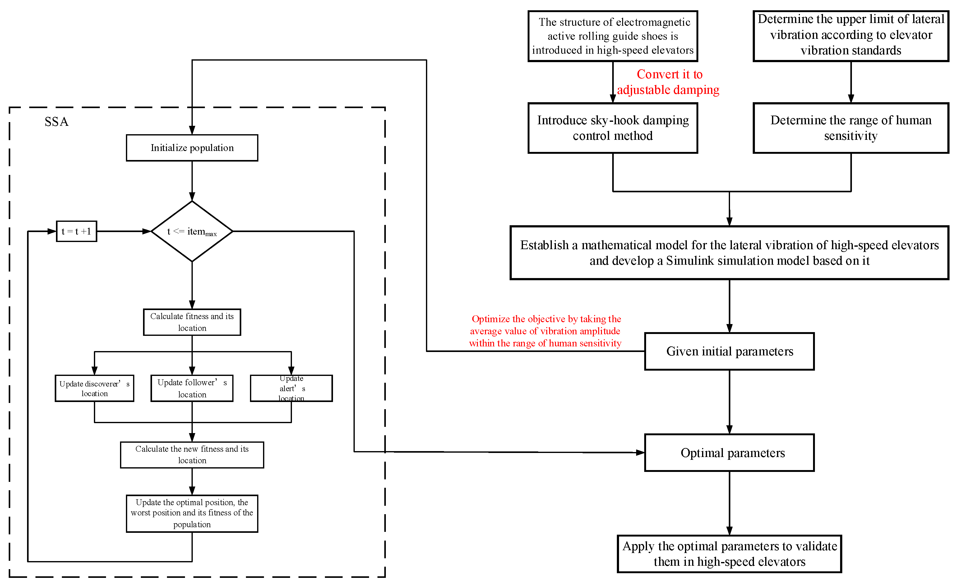
Ultimately,
Figure 3 depicts the flow chart of the lateral vibration control strategy of a high-speed elevator, with the main steps as follows:
- (1)
Replace the traditional guide shoes in the cabin guiding device with electromagnetic active roller guide shoes to reduce the impact on the cabin caused by uneven guide rails.
- (2)
To overcome the drawbacks of the electromagnetic active roller guide shoes, introduce a sky-hook damping control strategy to avoid the increase in cabin vibration due to the damping force generated by the electromagnetic active roller guide shoes when the cabin’s motion speed and relative speed (cabin frame and cabin) are opposite.
- (3)
Establish three different types of mathematical simulation models for cabin motion in high-speed elevators, and then construct Simulink simulation models based on the sensitivity range of the human body to elevator vibrations.
- (4)
Introduce the SSA optimization algorithm and take the mean value of vibration amplitude within the sensitive range of the human body as the optimization objective. Optimize the damping coefficients c of the electromagnetic active roller guide shoes and the Cmin and Cmax in the sky-hook damping control strategy in all three motion modes of the simulation model to obtain the optimal solution.
- (5)
Apply the optimized parameters obtained from SSA to actual high-speed elevators to verify the effectiveness and advancement of the proposed cabin vibration control strategy.
4. Simulation Analysis
In general, the horizontal acceleration of the elevator car floor is considered a direct indicator of comfort. In order to better control the lateral vibration of high-speed elevators and improve ride comfort, this paper first searches for specifications of lateral vibration of high-speed elevators. Existing specifications state that the maximum peak-to-peak value of horizontal vibration during elevator operation should not exceed 0.20 m/s
2, and the A95 peak-to-peak value should not exceed 0.15 m/s
2 [
21,
22,
23]. Next, a Simulink simulation model is constructed based on the mathematical model of lateral vibration of high-speed elevators mentioned in the second section. An SSA optimization algorithm is then introduced to minimize the mean vibration amplitude within the range of human sensitivity as the optimization objective. This is performed to optimize five parameters: damping
of the electromagnetic active rolling guide shoes
and
of the sky-hook damping control strategy for the three movement modes of high-speed elevators. This is to obtain an optimal set of parameters. Finally, based on the optimal parameters, the high-speed elevator is adjusted for actual testing to verify the effectiveness of the lateral vibration control strategy proposed in this paper.
Generally speaking, the natural frequency range of the car transverse vibration lies in 0–10 Hz, and the human sensitive transverse vibration frequency is 1–2 Hz [
24,
25]. Therefore, only the amplitude within 0–10 Hz is considered in this paper. According to the derivation of the mathematical model of elevator car vibration, the Simulink simulation model is built for subsequent simulation analysis.
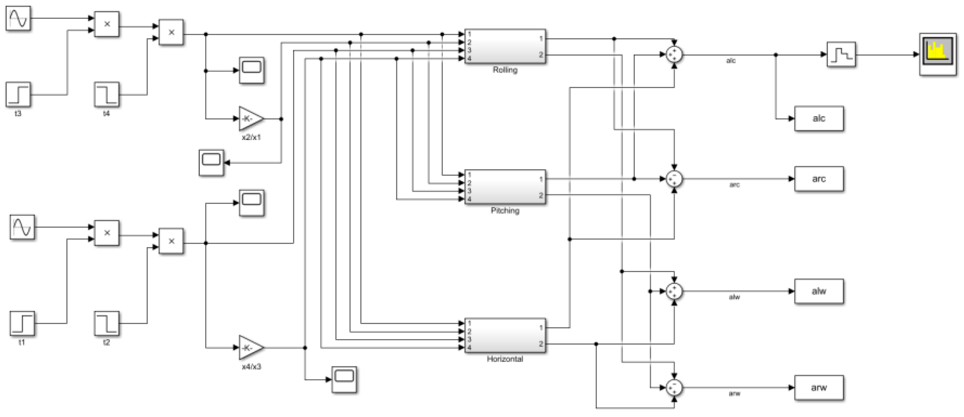
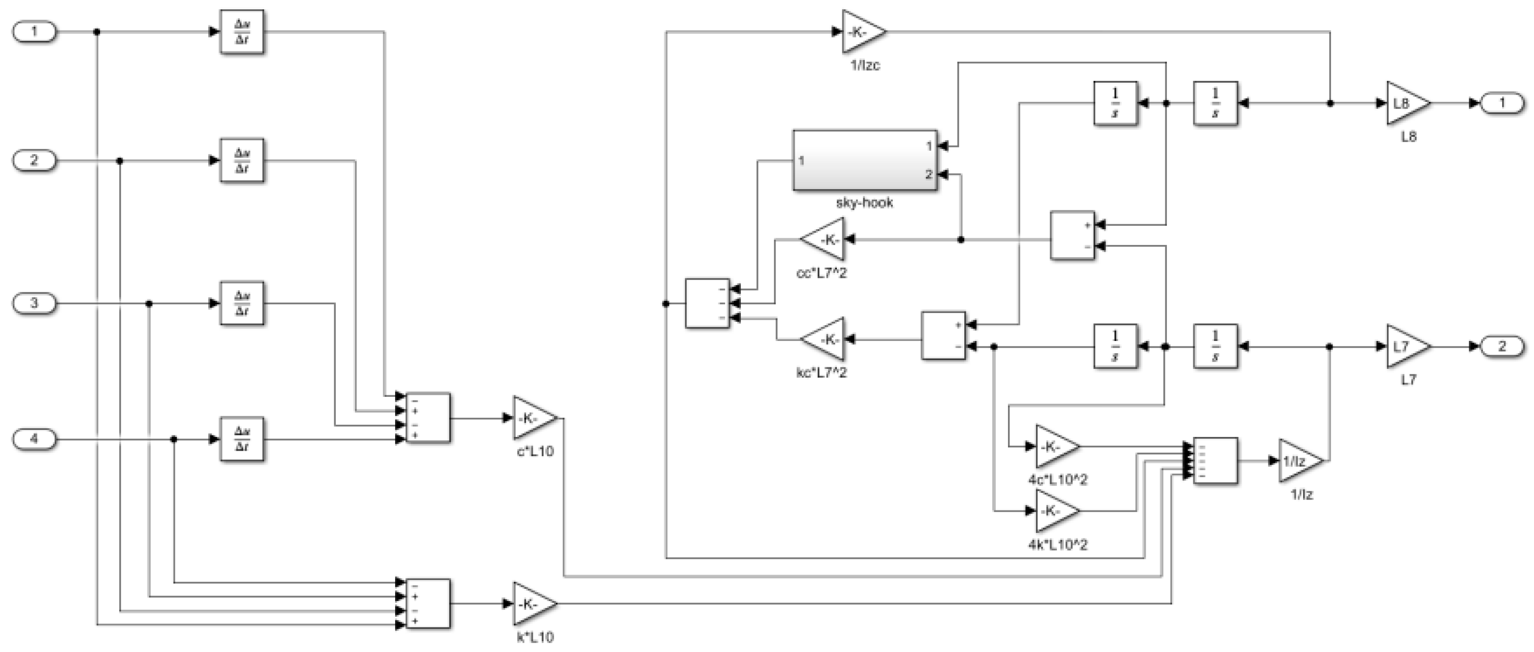
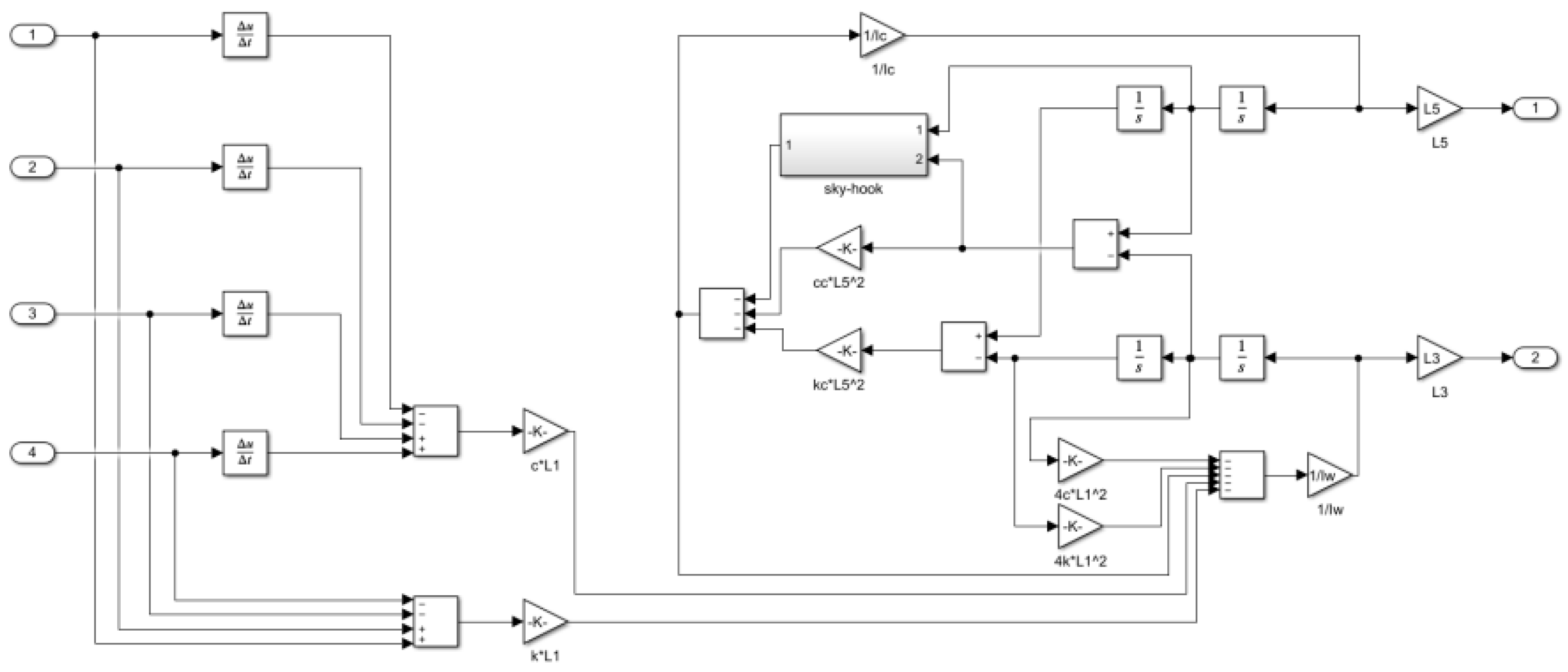
Figure 4 is the Simulink simulation model.
Figure 5,
Figure 6 and
Figure 7 express the Rolling, Pitching, and Horizontal motion models of the elevator car, respectively.
During the simulation process, an m-file is used to input the guide rail excitation. The damping coefficient of the electromagnetic active rolling guide shoes and the controller parameter settings are bounded using upper and lower limits, as shown in
Table 1. To demonstrate the superiority and applicability of the SSA algorithm in optimizing the parameters for controlling lateral vibration of high-speed elevator cars, a comparison is made by optimizing the corresponding parameters using the Genetic Algorithm (GA) [
26] on the same simulation model. The parameters for both optimization algorithms are set in the same way, as shown in
Table 2.
After calculation, the obtained fitness curve is shown in
Figure 8.
As can be seen from
Figure 8, SSA has a faster convergence speed and higher parameter fitness than those of GA. In terms of algorithm principle, GA mainly relies on crossover and mutation to get better results. It has a stronger global search ability but a poorer local search ability. In the later stage of evolution, the search efficiency goes low, which is prone to premature convergence. However, SSA has stronger local search ability and faster convergence speed. Given these advantages, the more reliable SSA was used for optimization this time, which can provide better optimization results.
Table 3 shows the optimal parameters obtained after optimization through SSA.
Then, the simulation results obtained from Simulink are imported into the analysis tool. The time-domain data in the workspace is processed using the Fast Fourier Transform (FFT) with a rectangular window function to obtain the frequency spectrum of the vibration signal. The frequency spectrum is used to evaluate whether the lateral vibration control results meet the requirements.
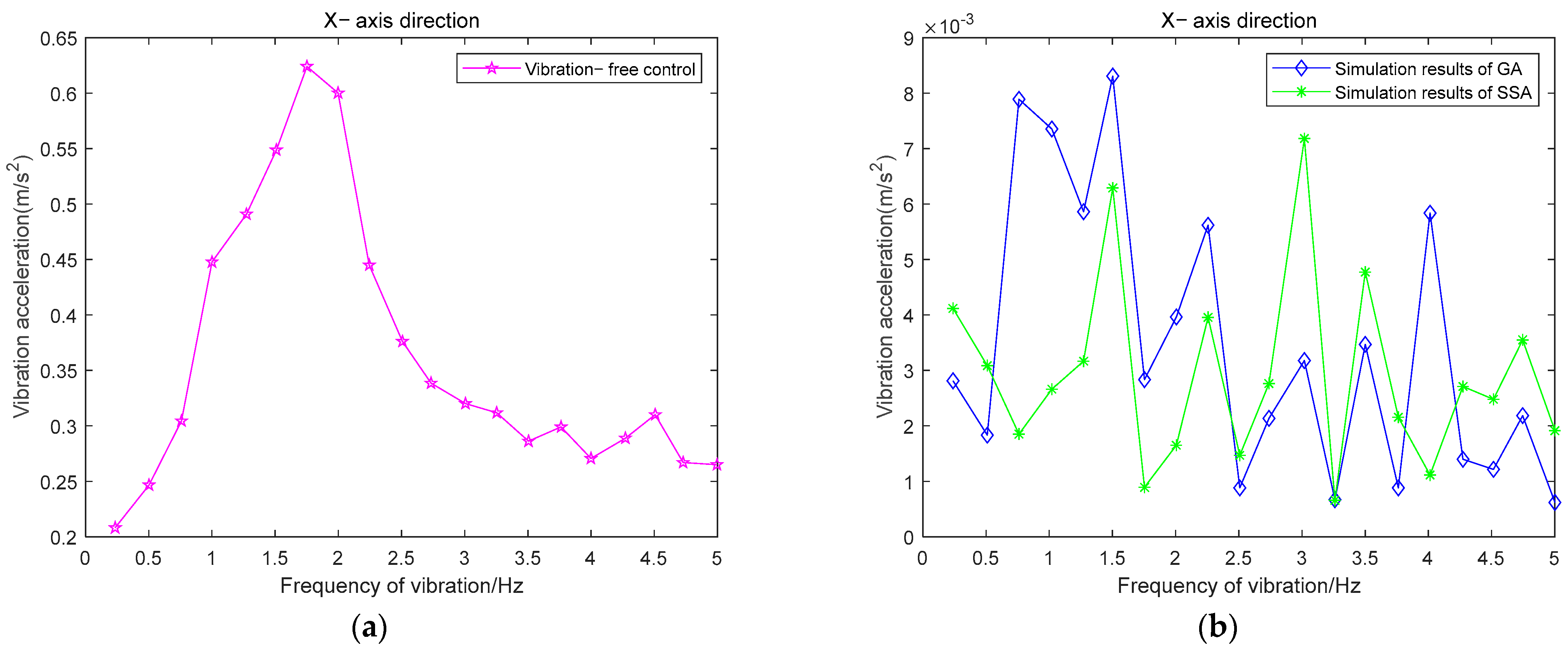
In order to further demonstrate the effectiveness of the proposed lateral vibration control method and the advanced nature of the SSA optimization algorithm, simulations are conducted according to the original parameters of the high-speed elevator (without vibration control) and optimized parameters of GA and SSA. During the simulation, the same guide rail excitation is applied, and the frequency spectrum graphs of the simulation results are shown in
Figure 9.
From
Figure 9, it can be observed that within the human sensitivity range of 1–2 Hz, the maximum amplitude of vibration without vibration control is 0.63 m/s
2, significantly exceeding the comfort standard of 0.2 m/s
2. However, after adjusting the parameters based on intelligent optimization algorithms, the vibration amplitude within 1–2 Hz decreases by two orders of magnitude, far below the comfort standard of 0.2 m/s
2. Moreover, most of the results from optimal parameters obtained through SSA are lower compared to those from optimal parameters by GA within 1–2 Hz. This demonstrates the effectiveness of introducing electromagnetic active roller guide shoes and sky-hook damping control in vibration control for high-speed elevators, as well as the efficacy of seeking optimal parameters through SSA.
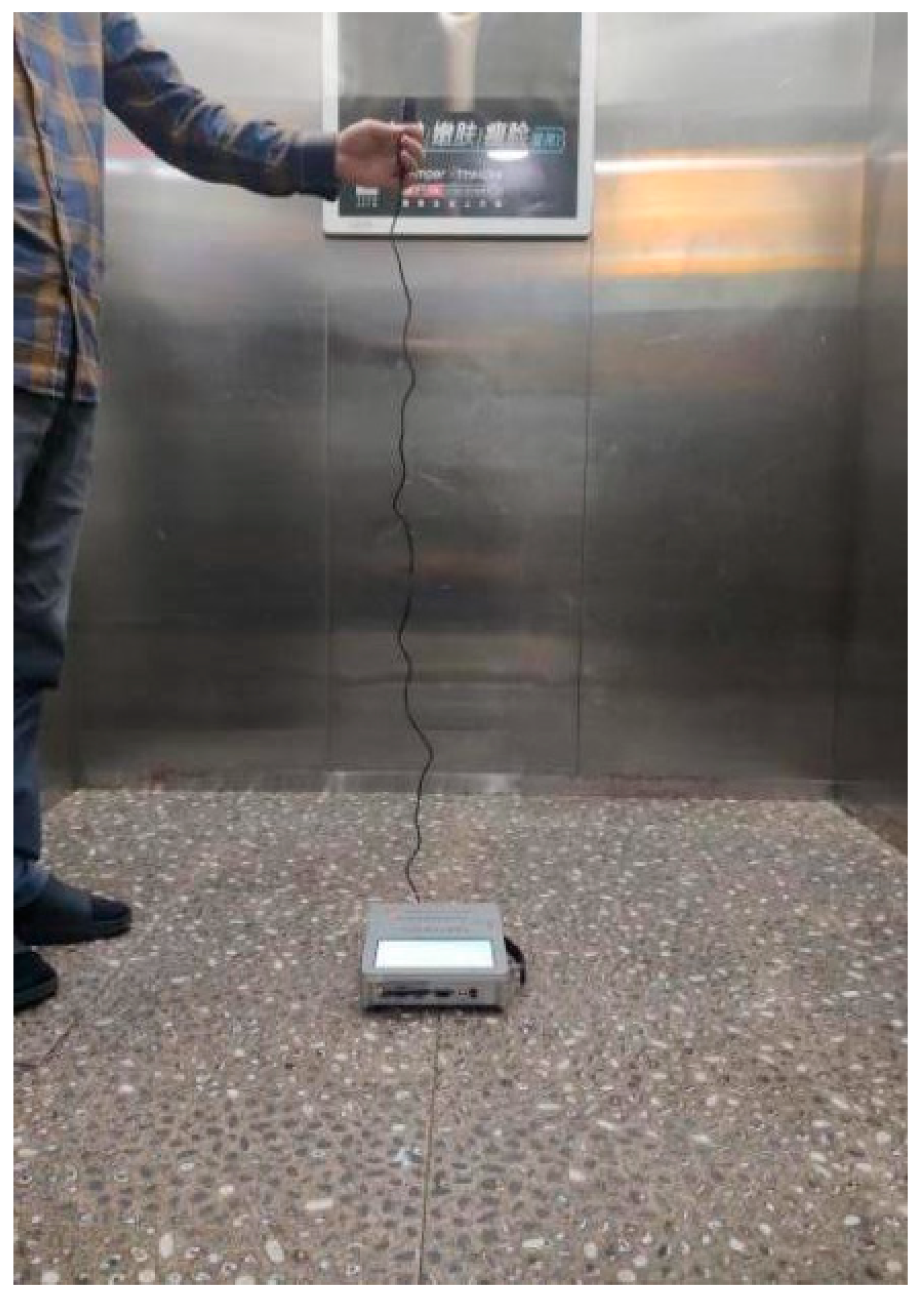
5. Experimental Analysis
High amplitude vibrations not only decrease passenger comfort but also cause damage to the components of high-speed elevators, reducing their lifespan. In order to verify the simulation results, the ATL-ERT2 high-precision elevator riding transportation quality tester was used to collect vibration data from a certain model of a high-speed elevator in Jiaxing City, Zhejiang Province, China, with a lifting height of 150 m and a running speed of 3.5 m/s
2. This test instrument is equipped with a MEMS high-precision three-axis accelerometer to measure the vibration acceleration in three directions of the car. The sampling frequency during the experiment was set to 2000 Hz. Before the experimental verification phase, structural improvements were made to the tested high-speed elevator, which included incorporating electromagnetic coils to form electromagnetic active roller guide shoes and introducing a sky-hook damping control strategy. Subsequently, the structural parameters of the high-speed elevator were adjusted based on the optimal parameters obtained from the simulation.
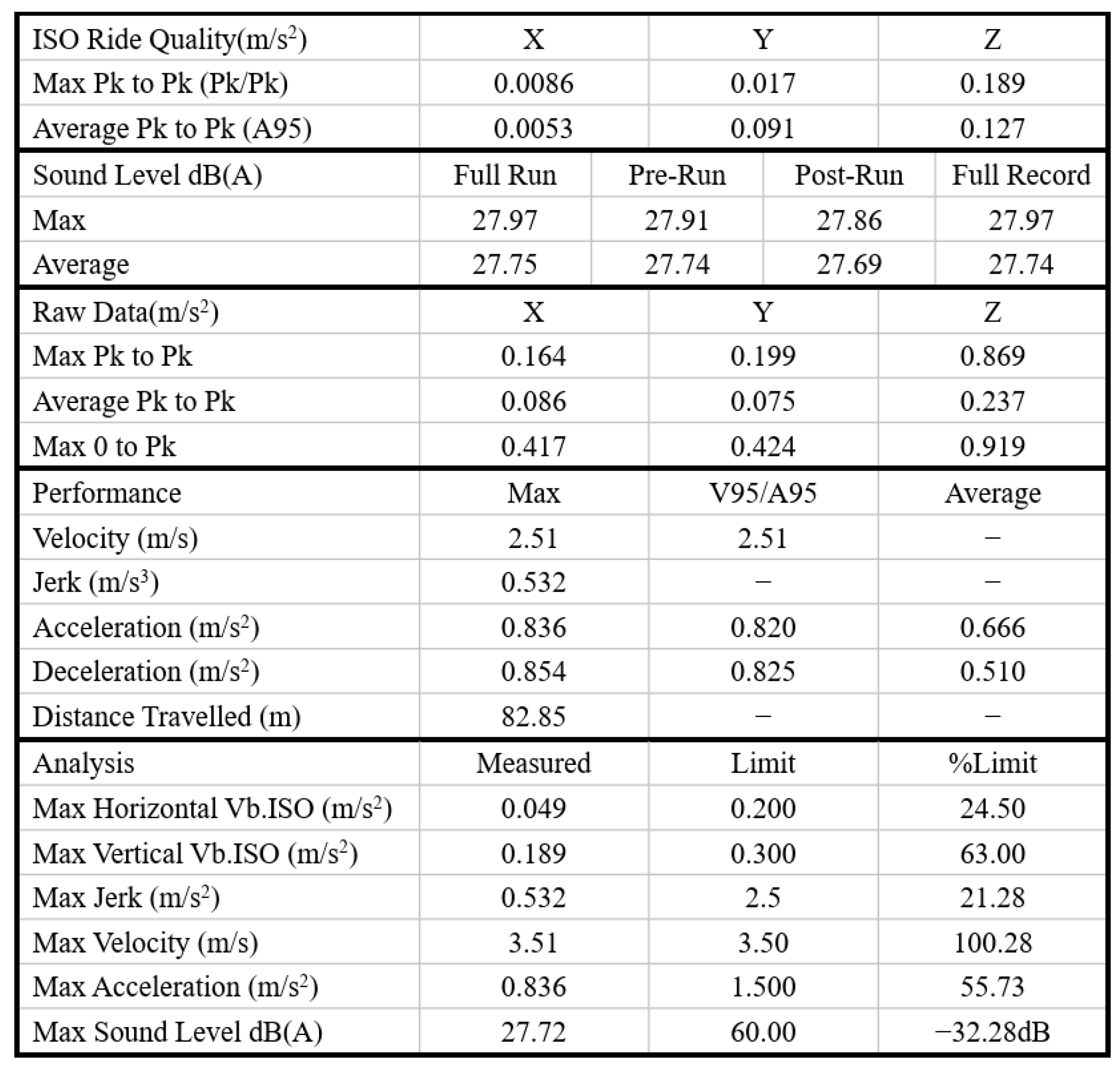
Figure 10 and
Figure 11 show the on-site testing photos and the collected results, respectively.
From the analysis of the test report, after adding the lateral vibration control strategy for high-speed elevators proposed in this paper, the maximum amplitude of the car on the X-axis and Y-axis is far less than 0.2 m/s2, which meets the comfort standard. The result fully indicates that the control scheme proposed above is advanced and feasible.
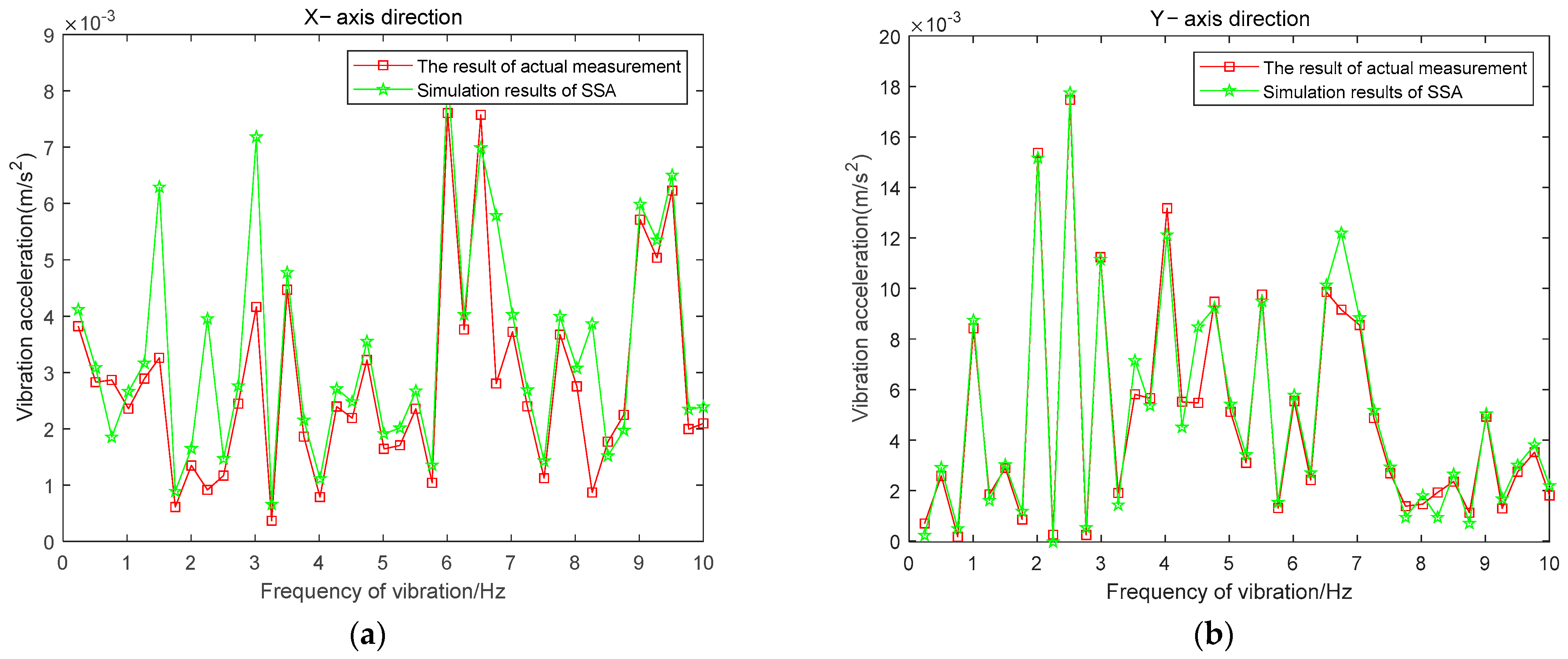
In order to further verify if the optimal parameters obtained from SSA are consistent with vibration acceleration results in both simulation and actual tests, so as to further demonstrate the correctness and effectiveness of the constructed simulation model, the simulated data and the measured data of the horizontal acceleration of the elevator car floor in the X and Y directions are compared. The results are shown in
Figure 12.
From
Figure 12, it can be observed that the simulated data are visually consistent with the measured results in terms of the specific fluctuation trend. The root mean square error (RMSE) is used as the evaluation metric for the fitness between the simulated and measured results, and its calculation formula is shown in Formula (19).
where
represents the total number of data,
represents the
data value in the actual test data,
represents the
data value in the simulated data.
The RMSE in the X-axis direction is 0.001, and in the Y-axis direction, 0.0008. Based on the RMSE values, it can be concluded that the optimal parameters obtained from SSA are highly consistent between the simulation and actual testing data.


