1. Introduction
The rapid evolution of modern wireless communication is causing serious electromagnetic (EM) interference. It seems that EM radiation has emerged as the fourth most important source of pollution in the environment, after air, water, and noise. Therefore, there is an increasing demand for the development of appropriate materials and techniques to suppress the consequences of EM radiation, and EM interference and EM compatibility have become very important. The presence of any disturbing EM wave source or an object reflecting the waves from the source affects the measurements and the operation of electronic equipment [
1].
It is vital that electronic equipment can perform accurately and reliably with electromagnetic compatibility across a wide frequency range (FR) without any interference [
2]. Due to the intense use of most frequency bands, the presence of a disturbing EM wave source at the measurement point causes errors in the measurements. In addition to damaging various systems and devices, EM waves also harm living organisms [
3].
Since concealment from enemy targets is one of the most important military needs, research on stealth technology has grown significantly over the past 25 years, the principal goal of which is to minimize the target’s scattered EM energy so that it becomes invisible to a radar receiver. The application of functional materials having radar/microwave absorbing capabilities is the only feasible solution for the implementation of stealth characteristics [
4]. To avoid the abovementioned problems, EM absorber materials are used [
5], because, due to their magnetic or dielectric losses, EM absorbers can absorb electromagnetic radiation. In the literature, microwave absorbers were developed in two different ways: multilayer and frequency-selective surface screen-based. Multilayer radar/microwave absorber (MRA/MMA) structures have drawn attention recently due to their improved absorption capabilities [
6]. Since the electrical and magnetic permeability of different materials varies according to frequency, the properties of the material used in the structure of the absorber are very important in terms of absorption performance.
Michielssen et al. (1993) identified 16 different types of materials to develop the microwave absorbers using a genetic algorithm (GA), comprising lossless dielectric, lossy magnetic materials, and lossy magnetic with relaxing type materials, all of which are frequency-dependent. A narrow, broad-band microwave absorber with a large angle of incidence is the best design for electromagnetic radiation suppression [
7].
Numerous criteria are considered while creating the ideal broadband microwave absorber, including operating frequency, incidence angle, wave polarization, material dielectric constants and permittivity, and layer thickness [
8,
9].
In the literature, many parameters are adjusted to obtain the optimum properties of the absorber by using various optimization techniques [
10,
11,
12], including the number of layers, dielectric constant, permeability, layer thickness, frequency, angle of incidence, and wave polarization [
13].
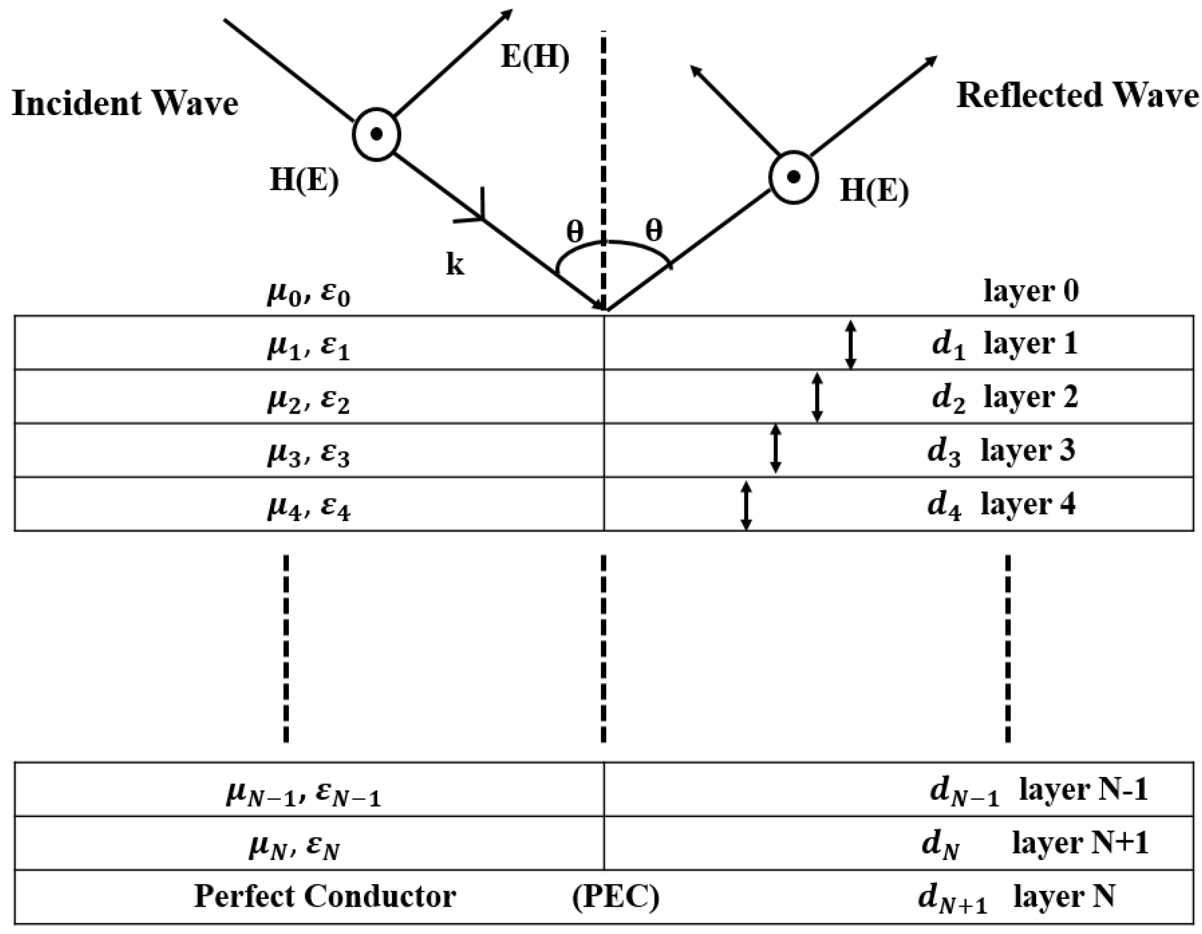
The main problem in constructing an absorber is to keep the reflection coefficient (RC) of an incident wave on a multilayer structure as low as possible for a variety of frequencies and incidence angles [
14,
15]. Numerous studies in the literature address this issue [
16,
17,
18]. The RC depends on each layer’s thickness and electrical and magnetic properties. In the studies, the RC of multilayer structures is calculated using Chew’s recursive method [
15] at every angle of incidence [
8,
10,
19]. This formula is used to calculate the RC for both TE and TM polarizations. For normal incidence RC is calculated with the same equation for both polarizations [
7].
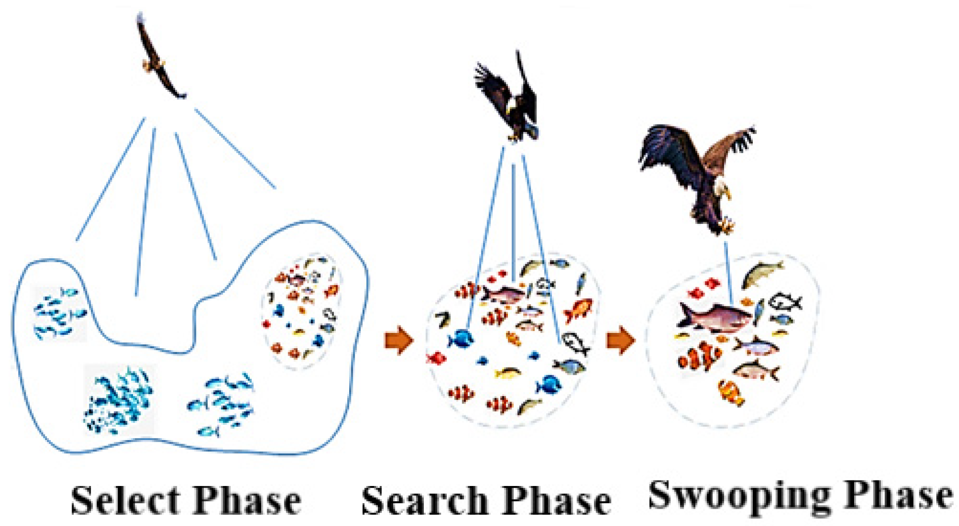
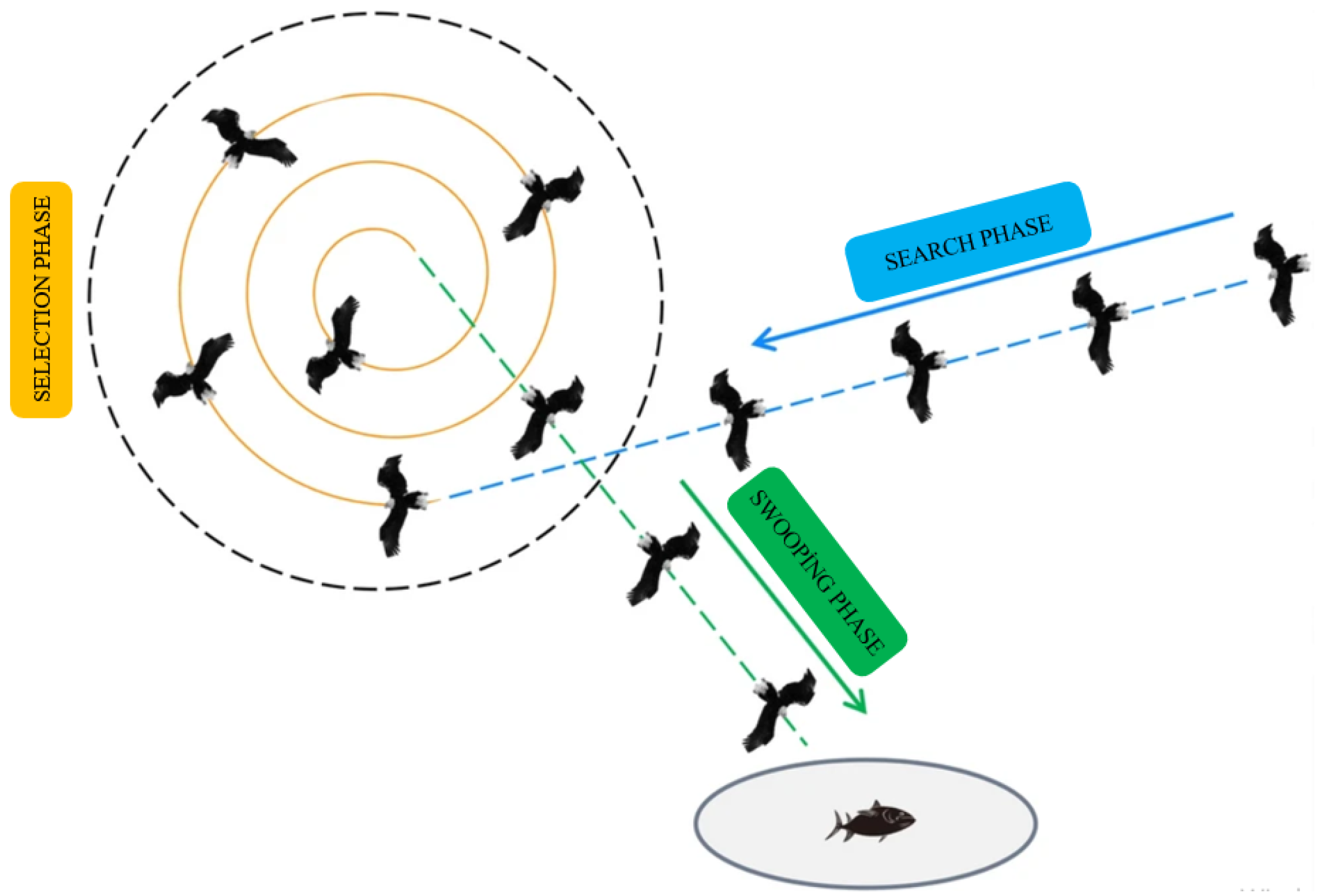
In this study, multilayer microwave absorber (MMA) designs in various FRs have been realized. These designs were produced using a new meta-heuristic process, the Bald Eagle Search Optimization Algorithm (BESOA), the utilization of which, to find the ideal MMA design for the required performance, was the main focus of this study. The aim of the study is to design MMAs with lower maximum RC and overall thickness, which turns the problem into a multiobjective optimization problem. The performances of MMAs were investigated for TE and TM modes and wide angle of incidence, for broadband frequency.
In-house prepared codes programmed with basic coding using MATLAB2021 software [
20] are used to calculate the reflection coefficient equations and to implement the BESOA. Codes to illustrate the performance of the designed MMAs by drawing the reflection coefficient graphs are also prepared similarly.
Literature Review
There have been various multilayer material structures created with different optimization approaches for the optimal design of MMAs, as shown in the following sample studies.
Michielssen et al. (1993) presented structure models for MMA structures in the FR of 0.2–2 GHz and 2–8 GHz, given a predefined set of materials with frequency-dependent electrical permittivity and magnetic permeability. Using a genetic algorithm (GA), they aimed to minimize the RC and the thickness of the absorber structure, and they simultaneously determined the optimal material selection and thickness for each layer [
7].
Asi and Dib (2010) modified the CFO algorithm to design the optimum MMA for normal incidence in a given frequency band. It was determined that the CFO findings were superior to those produced by the SADE algorithm, PSO, and GSA [
10].
Roy et al. (2015) compared the performances of different variations of the PSO algorithm to obtain the optimal designs of multilayer microwave absorbers over different frequency ranges, angles of incidence, and polarizations. Numerical optimal results were presented for each variation of PSO and the best results were compared with those available in the literature. Various absorber designs were obtained in the wideband frequency range in both TM and TE modes for normal and oblique incidences. In comparison to those described in the literature, the produced microwave absorber models obtained by Roy et al. (2015) were typically thinner and had a better frequency response [
13].
Yiğit and Duysak (2019) proposed a double-stage artificial bee colony (DS-ABC) algorithm for the optimal design of an MRA. The number and order of layers were evaluated separately from the thicknesses The developed MRAs were compared to those optimized by other techniques, demonstrating that the DS-ABC approach outperformed others in terms of finding the ideal layer order and matching thickness [
21].
3. Results
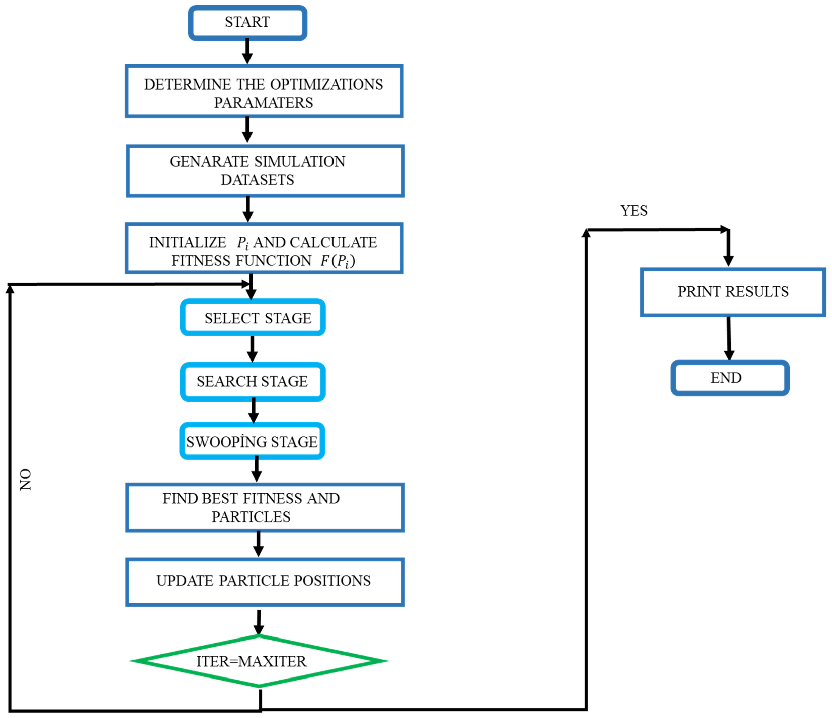
The BESOA was used to design multilayer electromagnetic absorbers for the microwave frequency band. The materials and thicknesses of layers were considered to minimize the maximum RC in the required FR. Chew’s recursive formula (Equation (1)) was used to calculate the RC of the MMA for both TE and TM polarizations. The optimizations were performed for both normal and oblique incidences. The BESOA was used to build microwave absorbers for a variety of material combinations, several layers, a large FR, and a broad angle of incidence; these MMAs were then compared with existing ones.
In the optimization process, the population of eagles was set to 50. The dimension, which stands for the layers and their corresponding thicknesses, was considered as two times the number of layers. The maximum layer thickness was set to 1.5 mm to restrict the search boundary. For each design, 20 independent trials were performed with 150 iterations. The best results and their comparison with the recent literature are presented. Sixteen MMA designs with the least maximum RC and the thinnest overall thickness are obtained and compared with 25 different designs. Thirteen of them have lower maximum RCs and thinner overall thickness. The optimum designs are obtained with less than 100 iterations. Referring to the literature, it is seen that the maximum iteration number for DE [
16], CFO [
10], PSO [
11,
13,
18], GSA [
10], and LSA [
12] is 1000. This value is 650 for DS-ABC, which is 150 is for the first stage and 500 for the second stage. The fewer the iterations, the less the computation time. The optimizations are performed on Intel (R) Core (TM) i7-6700HQ CPU (2.60 GHz; 2.59 GHz with 16 GB). The execution time for BESOA with a population of 50 is calculated as 798.531 s for 20 trials.
A FR of 1 to 20 GHz was considered. The MMAs were designed for 2–8 GHz, 12–18 GHz, 2–18 GHz, and 1–20 GHz FRs, and the frequency increment was set to 0.1 GHz. The angle of incidence varied from 0° to 75°for a set size of 15°. Here, φ1 and φ2 were considered as 1 and 1000, respectively.
3.1. Normal Incidence
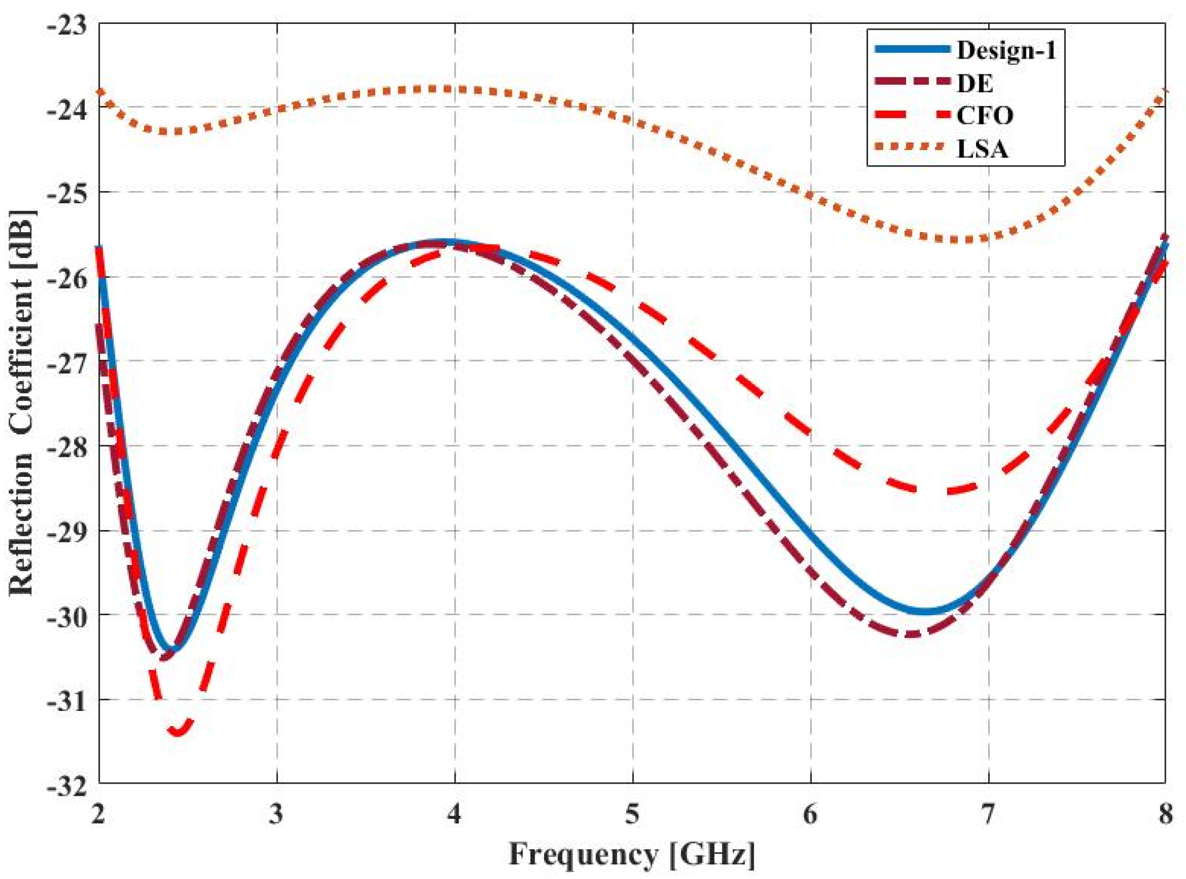
3.1.1. Design-1
A five-layer microwave absorber was designed in the FR of 2–8 GHz for normal incidence. The materials and thicknesses of layers were optimized to minimize the maximum RC in this FR. The maximum total thickness was set to 5 mm in the optimization process. The parametric comparison of the optimized design with the existing designs obtained by DE [
16], CFO [
10], and LSA [
12] methods is shown in
Table 2. The maximum RC of the proposed design was −25.765 dB. Although its total thickness was slightly larger than the design in Asi and Dib (2010) [
10], it was less than the design in Dib et al. (2010) [
10] and Lu and Zhou (2017) [
12]. Visual comparisons of the RC curves versus frequency are shown in
Figure 5.
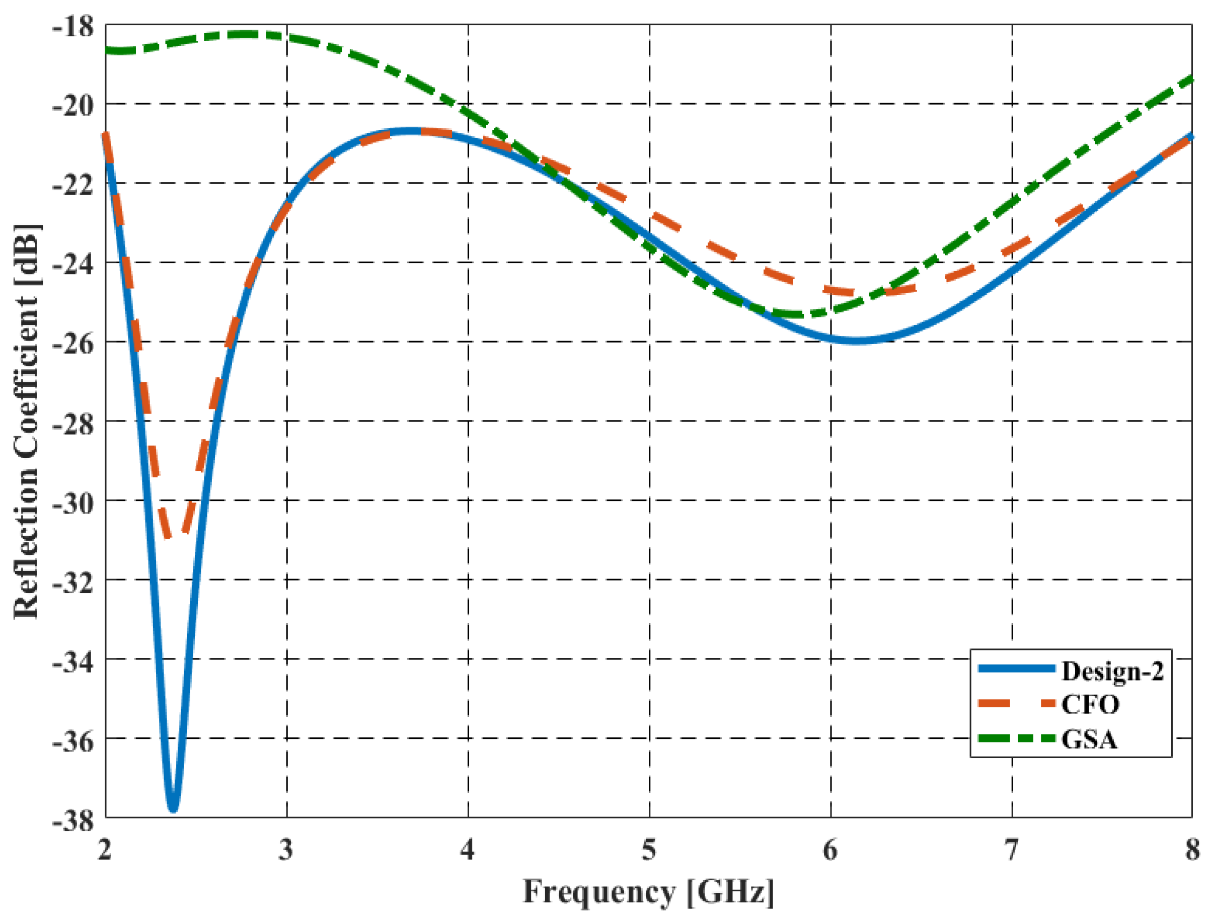
3.1.2. Design-2
Design-2 was optimized for normal incidence for the 2–8 GHz FR. The maximum total thickness of the MMA was set to 2.55 mm. The MMA with the required total thickness (2.55 mm) and a maximum RC of less than −20 dB (−20.1799 dB) was obtained. Compared with [
10], the maximum RC value obtained is also lower than the designs obtained by the CFO (−20.6994 dB) and GSA (−18.264 dB) (
Table 3). The comparison of the RC vs. frequency is illustrated in
Figure 6.
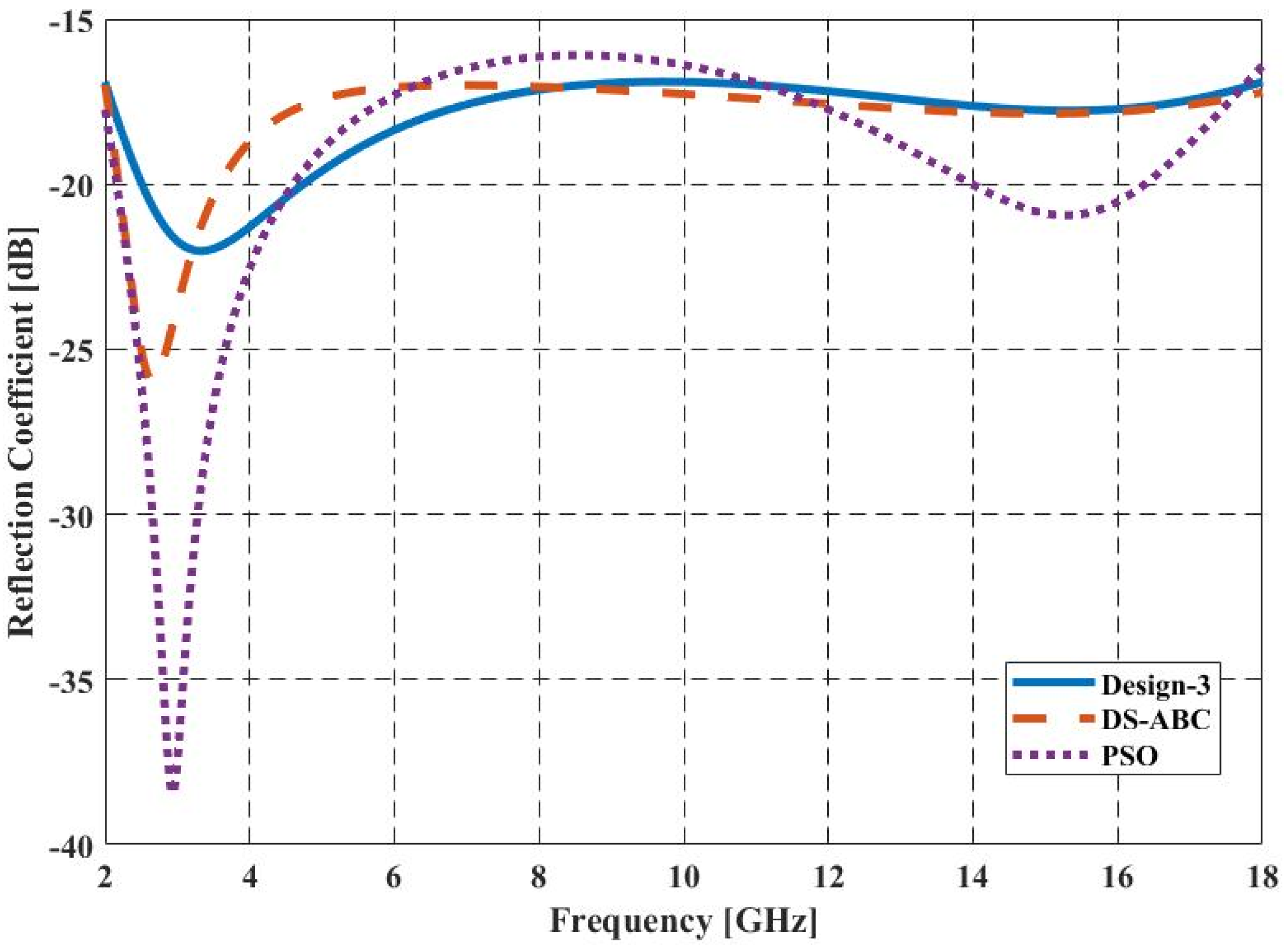
3.1.3. Design-3
Five-layer microwave absorbers were optimized for a 2–18 GHz FR for normal incidence (Design-3). The materials and thicknesses of layers were optimized to minimize the RC in this FR. Optimization was carried out by scanning the FR with 0.1 GHz frequency increments.
The optimized design parameters are compared with similar designs in the literature (
Table 4). The maximum RC for the proposed design is −17 dB and the overall total thickness is 3.20 m. The visual comparison of the RC versus FR is also given in
Figure 7.
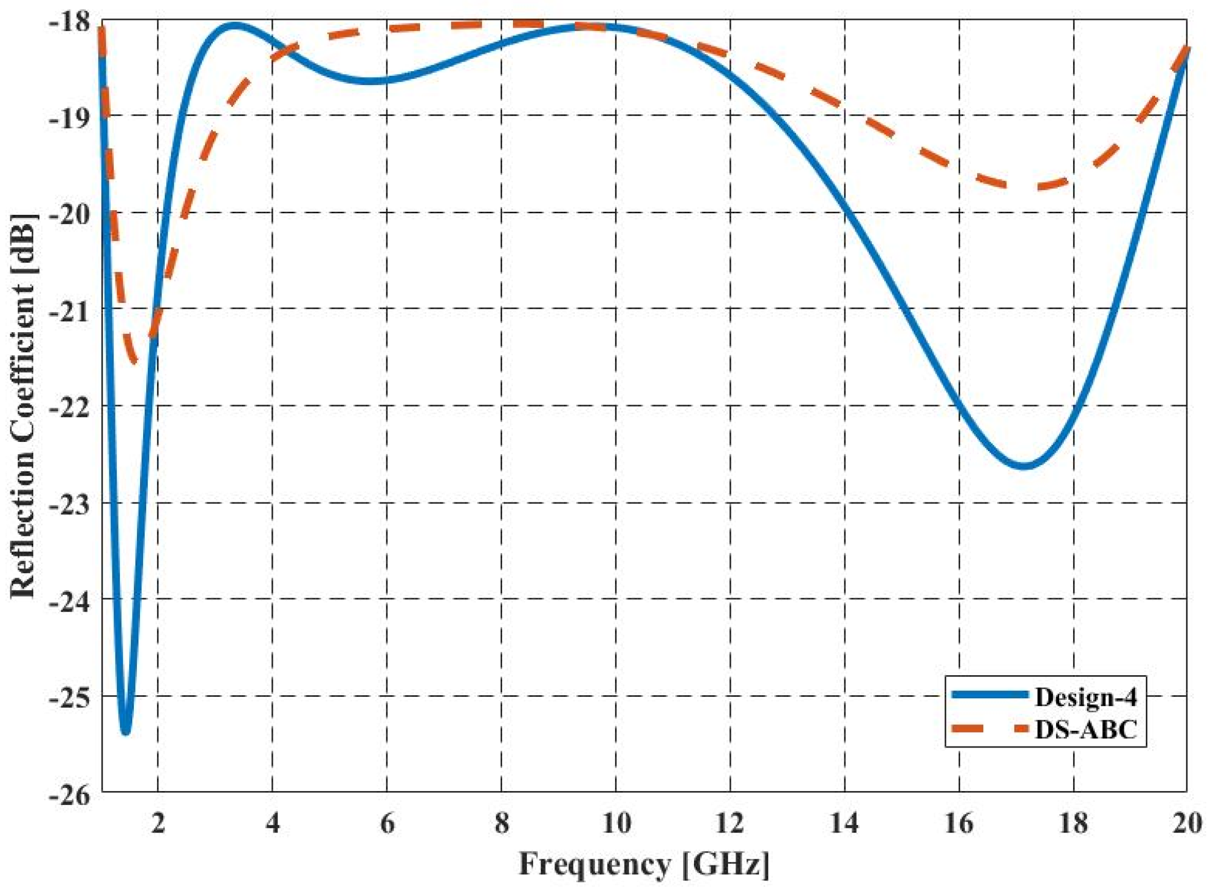
3.1.4. Design-4
Five-layer microwave absorbers were optimized for a 1–20 GHz FR for normal incidence (
Table 5). The materials and thicknesses of layers were optimized to minimize the RC in this FR. An MMA for a maximum RC of −18.0721 dB with a total thickness of 4.69 mm is designed. The comparison of RC versus frequency with similar designs is illustrated in
Figure 8.
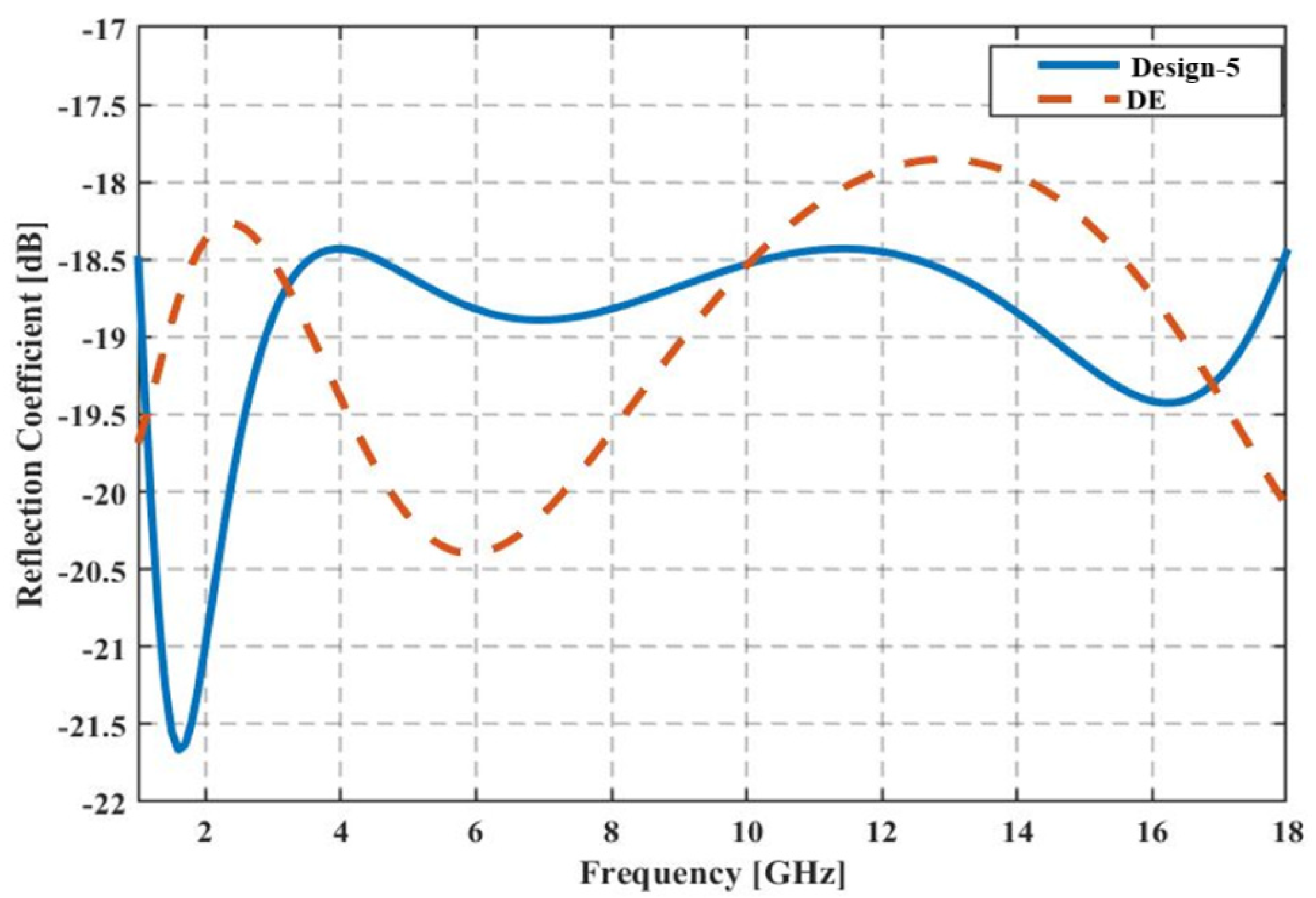
3.1.5. Design-5
A 7-layer MA was designed for applications in the FR of 1–18 GHz. Design-5 has the least total thickness (6.5 mm) and RC (−18.4311 dB) as compared to a similar design (
Table 6). For visual comparison, the RC versus frequency is also illustrated in
Figure 9.
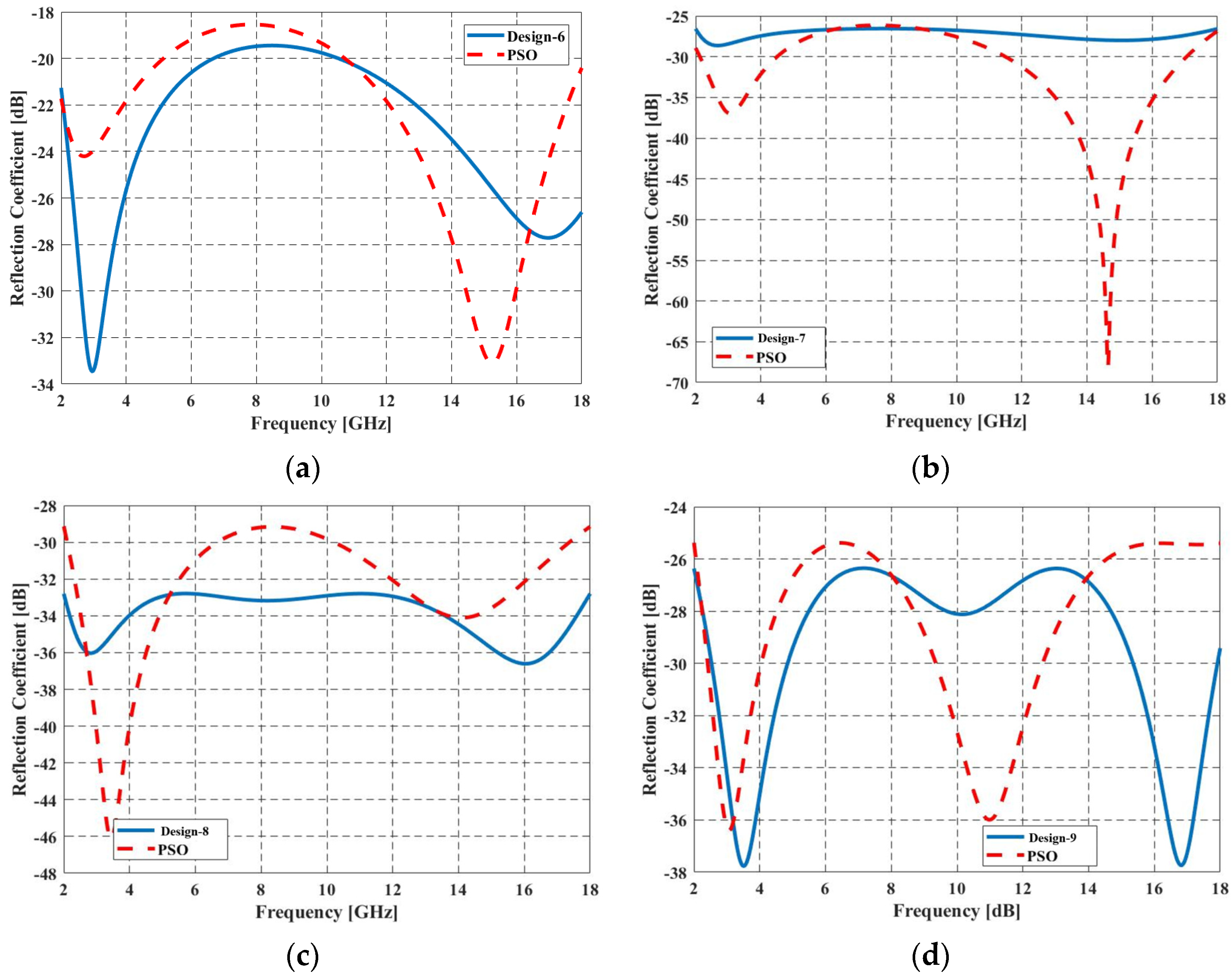
3.2. Oblique Incidence
The design parameters of MAs, Design-6, Design-7, Design-8, and Design-9, for different oblique incidences of TM polarization, are given in
Table 7. Each design was obtained for a single angle of incidence that varied from 30° to 75°, with 15° angle increments. All designs had the least total thickness and reflectivity (<−20 dB) when compared to similar designs in the literature. The overall thickness and the maximum RC are −3.401 mm and 20.8919 dB for Design-6, 3.84 mm and −26.5667 dB for Design-7, 3.966 mm and −32.7952 dB for Design-8 and 3.125 mm and −26.3625 dB for Design-9. The obtained results show that the method allows the realization of broadband/wide angle MMA designs.
Figure 10 illustrates the comparison of RL versus the required FR.
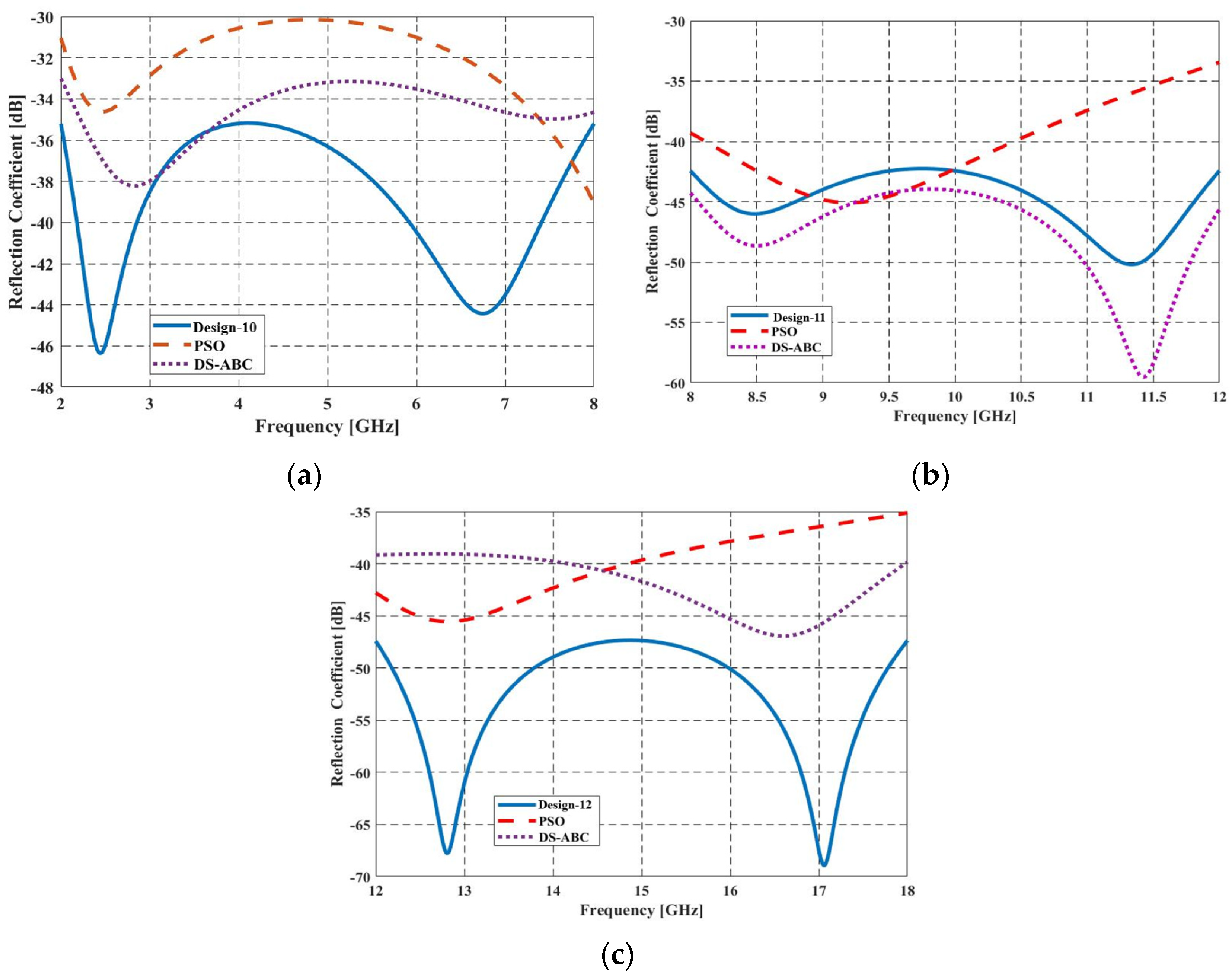
Three different MAs, Design-10, Design-11, and Design-12, were designed for the applications in the frequency bands 2–8 GHz, 8–12 GHz, and 12–18 GHz, respectively (
Figure 11). The design parameters for 45° oblique incidences for TM polarization are shown in
Table 8. For Design-10, the maximum RC and total thickness are obtained as −35.1971 dB and 3.90 mm, respectively. These values are −42.2578 dB and 2.47 mm for Design-11, and−47.3111 dB and 2.07 mm for Design-12. Compared to the most recently designed MMA with the best maximum RC and thickness presented in [
21]: For Design-10, a design of 0.09 mm thinner with a maximum RC at least 2 dB less is obtained. Although the maximum RC value is higher than [
21], an equal overall thickness is obtained for Design-11. A 0.0.25 mm thinner design with a maximum RC 8.211 dB less is obtained for the 12–18 GHz frequency band (Design-12).
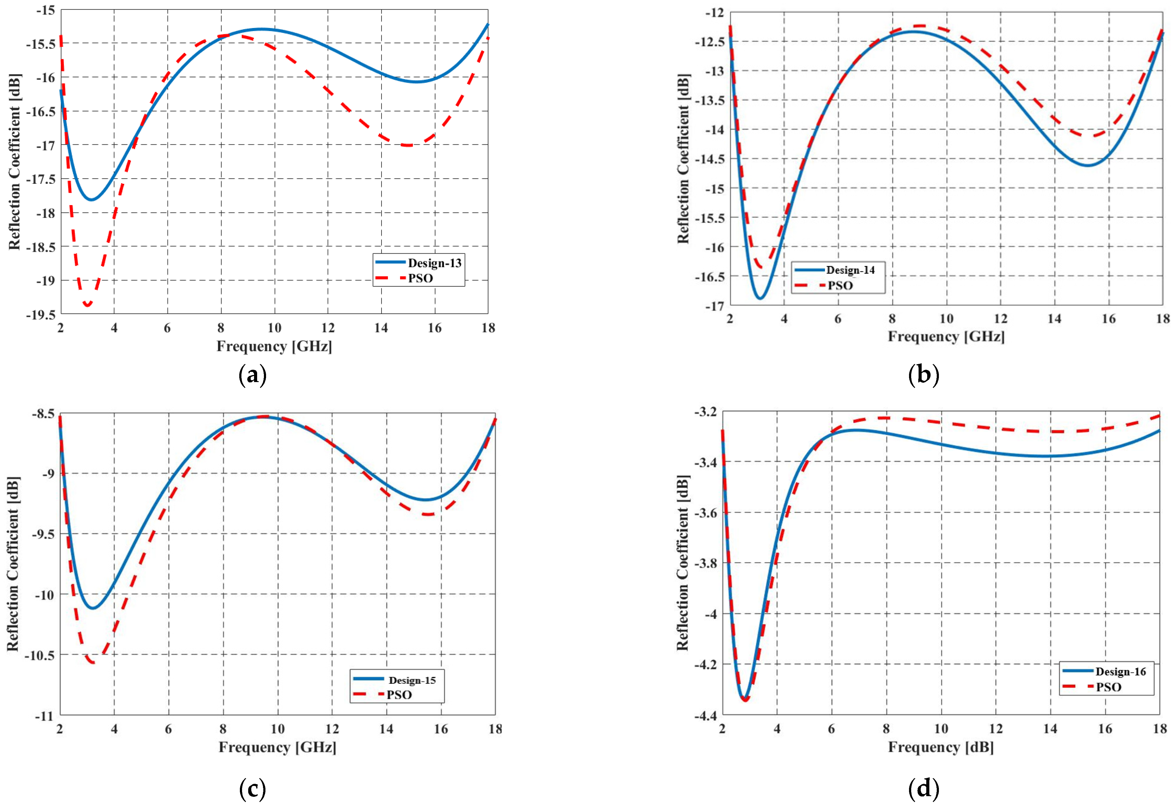
The design parameters of MAs, Design-13, Design-14, Design-15, and Design-26, for different oblique incidences for TE polarization, are given in
Table 9. Each design is obtained for a single angle of incidence which is varied from 30° to 75° with 15° angle increments. Although the designs for TE polarization outperform the existing designs, the comparison of the
Table 8 and
Table 9 reveals that the TM polarization provides a lower RC.
Figure 12 illustrates the comparison of RC for TE polarization versus the required FR. The maximum RC values for the obtained designs are −15.50209 dB, −12.3418 dB, −8.54521 dB, and −3.2771 dB for Design-13, Design-14, Design-15, and Design-16, respectively, which are above the −20 dB.
4. Discussion
BESOA is a recently introduced optimization algorithm used to optimize the sequences of materials and thickness of the layers to obtain optimum MMAs with less overall thickness and lower RC for a wide FR and angle of incidence. Its performance is studied in the design of wideband MMAs; the results are compared to similar designs obtained by other well-developed algorithms, such as DE, PSO, GSA, CFO, LSA, and DS-ABC. In this study, for consistency, 16 dielectric and magnetic materials, which have been used to design MMAs in the literature for the last 25 years, are preferred. The optimized MMAs are thinner and have a lower RC than the designs presented in the literature and the results of BESOA are comparable to those obtained by other algorithms. The BESOA converges to the minimum with less than 100 iterations.
5. Conclusion
Sixteen MMA designs with the least maximum RC and thinner overall thickness were obtained and they were compared with 25 different designs. Thirteen designs had lower maximum RCs and thinner overall thickness; one of them had the same thickness as the design against which it was compared, but had a lower RC; one of them had the same thickness and maximum RC values as the literature; and one had the same thickness value but a slightly higher RC of −42.2578 dB.
The results showed that designs obtained for TM polarization for oblique incidences from 30° to 75° (Design-6, Desihn-7, Design-8, and Design-9) had a maximum RC value lower than −20 dB. The maximum RC values of the MMAs for TE polarization for oblique incidence were −15.50209 dB, −12.3418 dB, −8.54521 dB, and −3.2771 dB for Design-13, Design-14, Design-15, and Design-16, respectively, which were above the −20 dB.
Although the maximum iteration number was set to 150 for BESOA, at the end of 100 iterations, it was possible to reach the best solutions. The maximum iteration number for DE [
16], CFO [
10], PSO [
11,
13,
18], GSA [
10], and LSA [
12] was set as 1000. This value was 650 for DS-ABC that was 150 for the first stage and 500 for the second stage. The less the iteration, the less the computation time. Although the execution time for BESOA with a population of 50 is calculated as 798.531 s for 20 trials, with the predefined computer, evidence of this value is not found in the literature for the other algorithms for this optimization problem, for comparison.


