Review

Advancements in Electrical Steels: A Comprehensive Review of Microstructure, Loss Analysis, Magnetic Properties, Alloying Elements, and the Influence of Coatings

1
Magnetics and Materials Research Group, School of Engineering, Cardiff University, Cardiff CF24 3AA, UK
2
Department of Electrical and Electronics Engineering, College of Science and Technology, Qaminis P.O. Box 10, Libya
*
Author to whom correspondence should be addressed.
Appl. Sci. 2023, 13(18), 10283; https://doi.org/10.3390/app131810283
Submission received: 15 August 2023 / Revised: 29 August 2023 / Accepted: 11 September 2023 / Published: 13 September 2023

Abstract

:
Electrical steels play a crucial role in modern electrical devices and power systems due to their exceptional magnetic properties. This comprehensive review delves into the advancements in the field of electrical steels, focusing on key aspects such as microstructure, loss analysis, magnetic properties, alloying elements, and the influence of coatings. The microstructural characteristics of electrical steels are explored in relation to their impact on magnetic behaviour and overall performance. Loss analysis techniques are discussed, highlighting the importance of minimizing energy dissipation in applications. The intricate relationship between magnetic properties and material composition, including the role of alloying elements, is examined to elucidate the mechanisms governing magnetic behaviour. Furthermore, the influence of coatings on the performance of electrical steels is investigated, considering both protection against environmental factors and their impact on magnetic properties. Through a comprehensive synthesis of recent research, this review provides valuable insights into the multifaceted nature of electrical steels and sets the stage for further advancements in their design and application.

1. Introduction

Electrical steel, renowned for its exceptional soft magnetic properties, comprises specific steel grades utilized in electrical motors and transformers [1]. These grades primarily consist of iron–silicon (Fe–Si) and iron–silicon–aluminium (Fe–Si–Al) alloys, which are often available in the form of thin plates with thicknesses ranging from 0.35 mm to 0.5 mm [1].
These steel materials find diverse applications in transformer cores, generators, and motors, falling into two primary categories: grain-oriented electrical steel (GOES) and non-oriented electrical steel (NOES). GOES is cold-rolled steel containing 3% silicon, exhibiting grain orientations aligned in the rolling direction, and imparting excellent magnetic properties in that orientation. It is extensively used in transformer cores [2]. On the other hand, NOES is more common in drives and generators, featuring a cubic texture with specific planes aligned parallel to the layer and a uniformly scattered direction [100]. When examining how texture influences the magnetic characteristics of electrical steel, it becomes essential to have reliable quantitative parameters that can effectively define both the magnetic properties, which are the dependent variables, and the texture, which serves as the independent variable. Concerning the magnetic attributes, typical quantitative measures can be utilized, including core losses, permeability, coercive field values, remnant induction, and other features associated with the hysteresis curve. As for texture, it is important to consider the physical fact that the preferred magnetization directions within a Fe-single crystal are the [100] directions [3]. Analysing the magnetization curves of Fe-single crystals reveals that optimal soft magnetic properties emerge when the external field is applied along the [100] direction. Consequently, the most desirable texture for a soft iron core is one that maximizes the density of [100] crystal directions aligning with the magnetic induction’s flux lines. Since, in rotating applications, the flux lines are nearly evenly distributed across the laminated sheets, the optimal texture is that which enhances the prevalence of [100] directions within the sheet’s plane. This does not refer to the well-known Goss component ([110][001]), often observed in grain-oriented steels [4], but rather pertains to the orientations of the cube fibre, where [001] planes align parallel to the rolling plane. The latter texture components feature two coplanar [100] directions within the sheet’s plane, whereas the former component only presents one [100] direction within the lamellar plane.
Under alternating current (AC) magnetization, electrical steel generates heat and sound, leading to power losses through hysteresis, eddy currents, and hysteresis anomalous losses [5]. Transformers play a crucial role in efficient power delivery by stepping up or stepping down the voltage from high transmission levels (e.g., 400 kV) to lower voltages (e.g., 220–240 V) for residential and industrial use, thereby minimizing power losses during transmission [6]. However, magnetostriction, a change in a material’s length due to a magnetic field, can lead to cyclic magnetization and demagnetization, causing transformer hum noise that may inconvenience residents. While noise-isolating enclosures can mitigate this noise, they can be costly. Alternatively, modifying material properties, such as using coatings to eliminate surface closure domains, offers a potential solution to controlling magnetostriction and reducing transformer hum noise [7].
A growing trend in electrical steel production involves increasing the silicon (Si) and/or aluminium (Al) concentration beyond the traditional 3% weight composition. This trend is driven by the advantageous properties of these alloy compositions, such as their lower magnetic friction and magnetic contrast (K) values, coupled with higher electrical resistance. These characteristics contribute to reduced losses from eddy currents, making steel with higher Si and/or Al concentrations highly sought after [8].
Designed to possess specific magnetic properties including low hysteresis loss, low core loss, and high permeability, electrical steel is typically produced as cold-rolled strips with a thicknesses below 2 mm [5]. These strips are subsequently cut and stacked to create laminated cores for transformers as well as the stator and rotor components of electric motors. Various techniques such as punch and die cutting, laser cutting, or electrical-discharge-machining (EDM) wire cutting are employed to shape these strips into their final forms.
In recent years, significant efforts have been dedicated to developing improved steel grades that minimize iron loss and enhance energy efficiency [9]. One application of GOES involves using an effective coating that provides both insulation and tension, effectively reducing power loss in addition to magnetostriction. The magnetic activity and thickness of the coating are significant factors contributing to enhancing the stacking factor, indicating the quantity of the magnetic material in the core. Traditional coating systems like forsterite and aluminium orthophosphate typically have coating thicknesses ranging from 4 to 8 microns. However, it is essential to note that these non-magnetic coatings can reduce permeability and saturation, resulting in a stacking factor of approximately 96% [10].
In electrical steel, iron loss is conventionally divided into three categories: hysteresis loss, eddy current loss, and anomalous loss. Hysteresis loss is influenced by several factors, including the volume, size, and distribution of impurities; crystallographic orientation; and stress levels within a material. Eddy current losses can be mathematically described using the following equation
P e = π 2 6 ρ d 2 f 2 B p k 2
where
  • Pe—eddy current loss;
  • Bpk—max peak flux density;
  • F—frequency;
  • t—lamination thickness;
  • ρ—the electrical resistivity.
Electrical steel, an iron alloy with varying silicon (Si) content, spans a range from 0 to 6.5% (Si:5Fe). Nevertheless, common commercial alloys usually contain up to 3.2% silicon to prevent brittleness during cold rolling. Minor amounts of manganese and aluminium, up to 0.5%, can also be incorporated [11]. The introduction of silicon notably enhances the electrical resistance of the steel, diminishing induced eddy currents and narrowing the hysteresis loop, ultimately leading to reduced core losses [12]. However, elevated silicon content can render the alloy’s grain structure harder and weaker, impacting workability, especially during recycling processes; raising the silicon (Si) content within the steel results in heightened levels of hardness and brittleness. Additionally, the manufacturing of thin sheets through cold rolling, particularly with a Si content surpassing 3.5 wt%, becomes notably challenging. J. Shin et al. conducted an investigation [13] delving into exploring the steel’s hardness within the silicon content range of 5% to 6.5% by conducting micro/nano-indentation tests, while considering different compositions and heat treatment conditions. To ensure optimal characteristics, it is crucial to maintain low levels of carbon, sulphur, oxygen, and nitrogen during alloying, as these elements can yield compounds like carbides, sulphides, oxides, and nitrides. Even minute quantities of these compounds, with diameters as small as one micrometre, can heighten hysteresis loss and curtail magnetic permeability. Carbon exerts the most detrimental influence, triggering magnetic aging over time as it precipitates as carbides, resulting in increased energy loss. To counteract these effects, the carbon level is typically kept at or below 0.005%, and annealing the alloy in a decarburizing atmosphere, such as hydrogen, can aid in reducing carbon content [14].
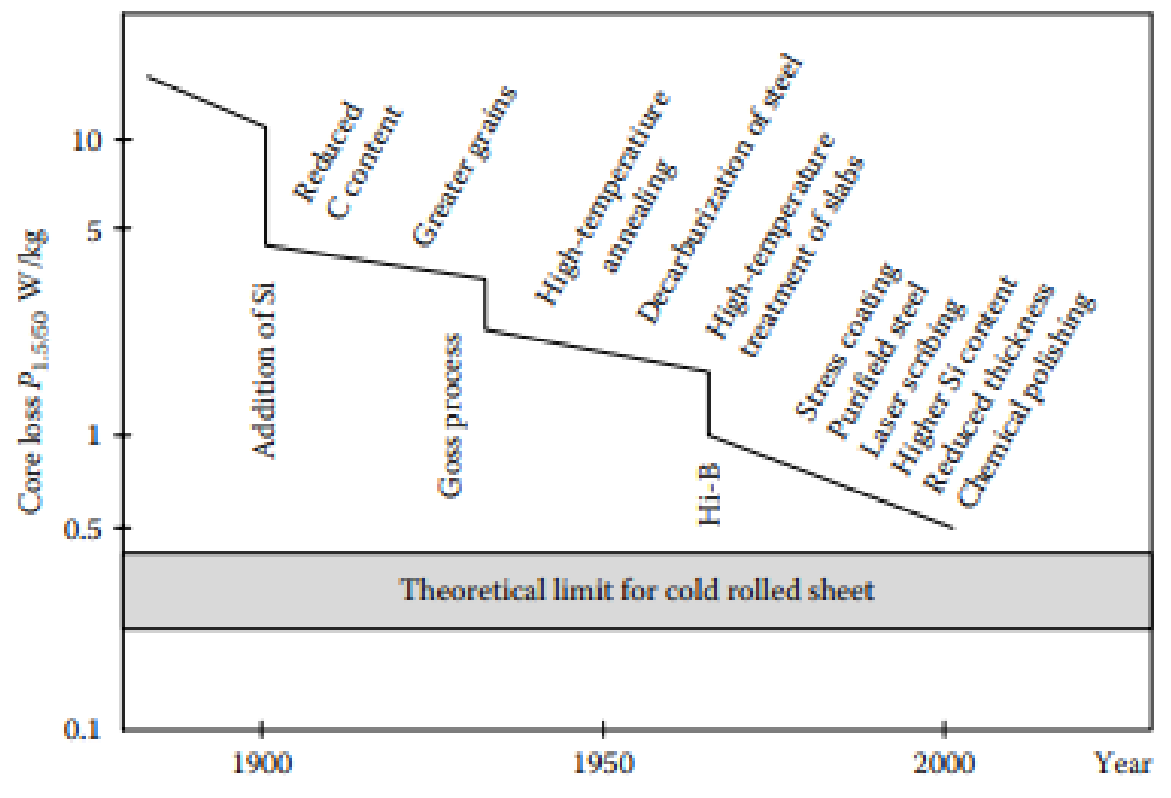
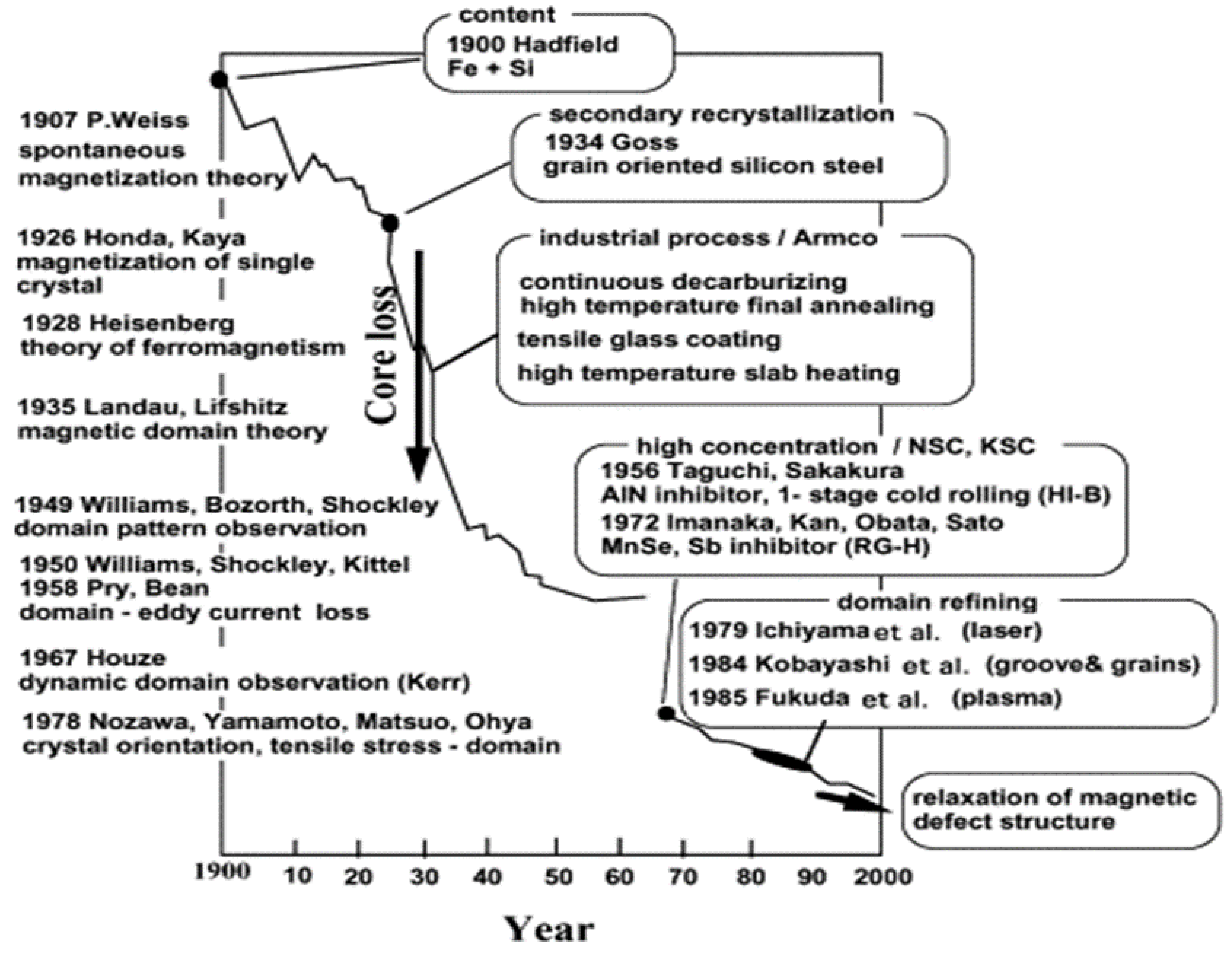
Presently, approximately 97% of all soft magnetic materials manufactured are electrical steels [15]. These steels collectively boast an annual amount of production surpassing 12 million tons, with roughly 80% constituting non-oriented (NO) grades and the remaining 20% being grain-oriented (GO) steels containing 3% silicon. The global demand for robust power generation and supply equipment has fuelled the development of low-magnetic-loss and high-permeability steels. Despite consistent progress over the years, as illustrated in Figure 1, magnetic losses in the central part of steel still contribute to 5–10% of the total electric power generated in advanced countries. While substantial breakthroughs in permanent magnets often involve entirely new material groups, improvements in electrical steels typically emerge from the introduction of new manufacturing processes and treatments [16].

2. Microstructure of Electrical Steel

The magnetic characteristics of soft magnetic materials, as electrical steel categories, are intricately linked to the microscopic structure and texture of the subsequent steel. The microstructural limits that play a significant role in magnetic properties, such as magnetization curves, permeability, coercive force, and specific magnetic loss, primarily include grain size, inclusions, internal pressures, the magnetic friction value, and surface defects. These microstructural factors govern the behaviour of the domain walls (coercive force) and their motion, these factors are responsible for shaping a material’s magnetic response, particularly at low- and medium-level magnetic fields. The crystalline structure further impacts magnetic behaviour, following various crystallographic guidelines. Specifically, [100] directions are even more susceptible to magnetization than other directional orientations. [110] or [111] or body-centred cubic (bcc) orientations (as depicted in Figure 2). In polycrystalline materials, the magnetic fabric influences the residual magnetic introduction and field rotation at high external magnetic field values.
For rotary machines, the optimal texture of electrical steel is a cubic fibre texture, where most grains have a normal [100] orientation in the sheet-planning machine. To enhance magnetic permeability and minimize overall power loss, the preferred microstructure is a coarse-grained configuration exhibiting a [100]//ND texture (known as the θ-fibre). This texture encompasses the cube, rotated cube, and all orientations where the [001] planes align with the sheet plane. This arrangement is advantageous due to its abundance of easy magnetization axes [001] within the sheet plane. Conversely, the [111]//ND (referred to as the γ-fibre) texture features hard magnetization axes [111] within the sheet plane, making it necessary to mitigate its presence in the final steel sheets [18,19]. An even spreading of crystalline orientations along these fibres results in most permeability and magnetic properties at the sheet level, and this class of electrical steel is known as NOES. Further, in applications involving static electrical machines like transformers, it may be preferable to use a distinct Goss texture [110] and [001] orientation since the magnetic field can align with the [001] direction [20]. Such steels have electrically oriented grains.
However, evaluating the effect of texture on magnetic properties presents challenges, as it is highly challenging to isolate its influence from factors like grain size or the presence of second-phase impurities in a material.
Figure 2. The magnetization curves for a single crystal of bcc iron [21].
Applsci 13 10283 g002
As the silicon content rises, the manufacturing process experiences higher temperatures, causing a slowdown in the production of non-oriented cold-rolled electrical steel. Consequently, the duration the finished strip spends in a furnace increases, resulting in a larger initial grain size. This, however, leads to a decrease in iron loss and an increase in magnetic induction intensity. The strong [111] surface texture in the final product of the electrical steel stems from intensive cold-rolling deformation, and even with continuous annealing, the dominance of the [111] texture persists. The continuous annealing process transforms the silicon steel structure into equiaxed ferrite overall but does not eliminate the genetic traits of microstructure and texture. Adjusting the annealing process counteracts the adverse effects of larger grain sizes, thus enhancing the [100] and [Goss] textures along with magnetic properties. Similarly, in non-oriented electrical steel, strategic process adjustments increase [100] and [Goss] texture content, thereby decreasing iron loss and enhancing magnetic induction. During normalization, Mn, Al, S, and N do not associate with Ti, whereas continuous annealing prompts the separation of secondary phases like AlN and MnS. The interaction of Ti with S, Fe, and O during normalization leads to compounds such as FeTiS and TiSO polymers. As depicted in Figure 3, the secondary phase particles within the tested steels of groups A, B, and C consist of polymerized and precipitated Mn, Ti, Al, S, and N elements [22].

3. Analysis of Losses in Electrical Steels

To precisely model and predict losses before assessing the impact of controlling material and physical properties, it is crucial to acknowledge potential errors in loss measurements, which are often overlooked in the profitable classification of electrical steels. These steels are primarily used in AC magnetic environments, and their magnetic properties are evaluated through testing under time-varying magnetic flux densities and sinusoidal waveforms, with maximum values of 1.5 or 1.7 tesla at 50 or 60 Hz, using methods such as the IEC Epstein square or the (SST) [23]. While these methods are well established for commercial classification, their use as research tools for studying loss mechanisms is limited and can be misleading because they do not provide accurate or absolute values of loss under ideal magnetic conditions.
A critical limitation arises from the necessity to assume a constant value for the length of the magnetic path in the Epstein square despite knowing that it varies with the material’s composition and magnetic conditions [24]. Recent reports have demonstrated that assuming this constant length leads to significant errors when comparing losses of similar steel grades [25]. In the worst-case scenario, although highly reproducible, the loss indicated by the Epstein square may deviate by 5–10% from the absolute value. In electrical machine cores, factors such as mechanical pressures, flux harmonics, and rotational magnetization introduce varying degrees of additional losses in different steel grades. Consequently, it is vital to ensure that these additional losses do not undermine the improvements achieved in the fundamental physical characteristics assessed using the Epstein test. The detrimental effects of these factors can be mitigated through the careful design and construction of the magnetic core, although they may result in an overall increase in basic losses by 10–30% [26]. Losses and other magnetic properties of the structure can be highly sensitive to mechanical pressures [27]. Given the challenge of eliminating various sources of stress in electrical machine cores, it becomes necessary to consider stress sensitivity curves, as shown in Figure 4, and ensure that any proposed new steel exhibits stress characteristics at least as good as those of the original material [28]. However, applying these properties directly to predict core losses is challenging due to the random and varied distribution of stress in large cores, where localized pressures may play a significant role [27].

4. Conventional Method for Studying Losses in Electrical Steels

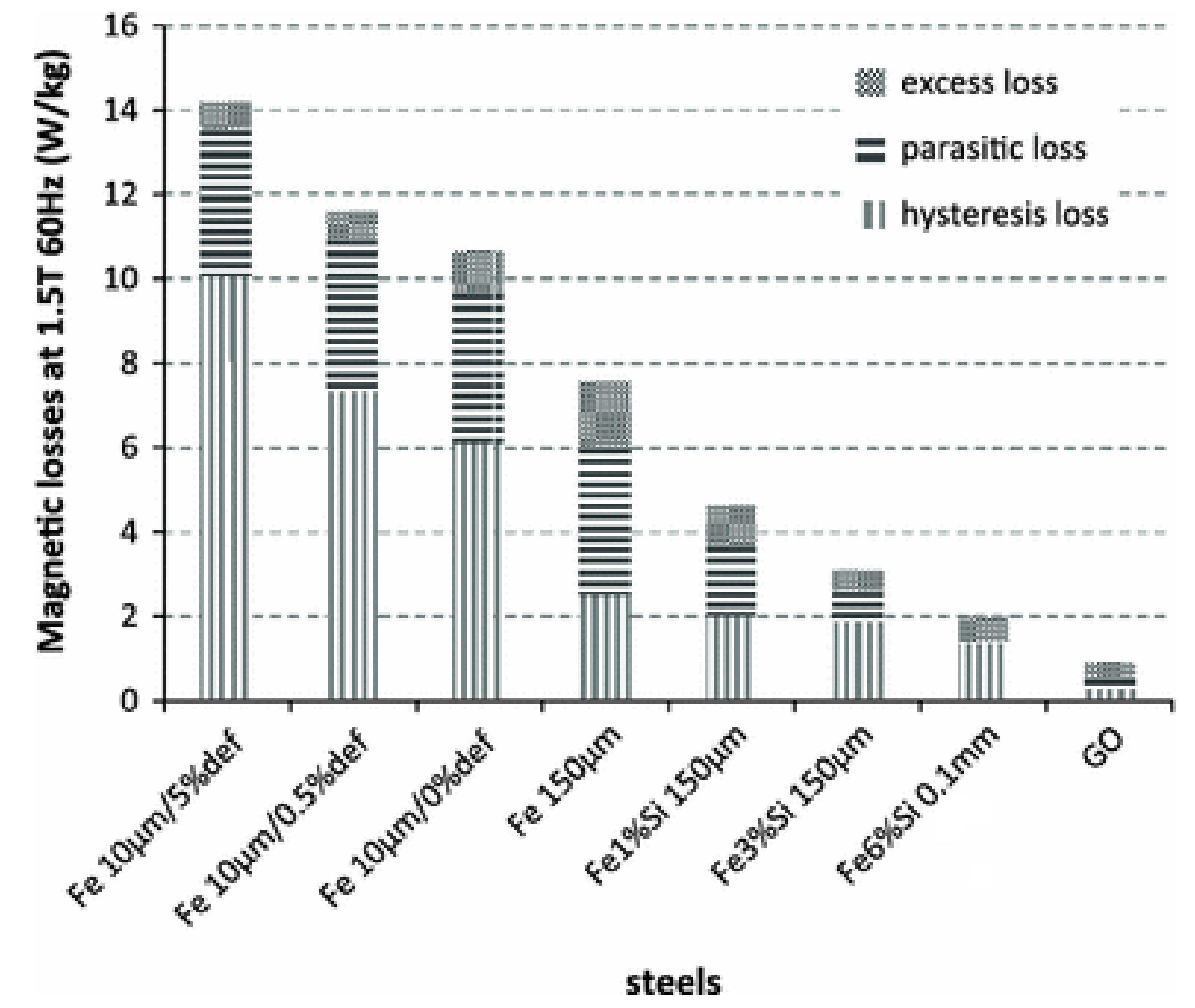
The manufacturing processes of electrical steels play a crucial role in determining these steels’ total losses. Plastic deformation increases hysteresis loss while reducing excess losses, whereas annealing promotes grain size growth, resulting in a decrease in the former and an increase in the latter (as depicted in Figure 5). In the case of non-oriented electrical steels, the total losses, at 1.5 T and 60 Hz, vary from 10 W/kg to 3 W/kg in the annealed condition, as indicated in steel manufacturers’ catalogs [29].
Motors, generators, and transformers are vital components in power systems, and their efficient design is essential to ensure regular power delivery while minimizing power loss. Recent research in this area has primarily centered around optimizing power loss. The consideration of power loss is a crucial aspect of machine design, and the core material’s magnetic properties at special frequencies play a significant role. Consequently, there is fierce competition between material designers to develop the most efficient materials with minimal power loss [30].
In these machines, power loss is commonly distributed into three components: copper loss (Pcu), which occurs in the machine windings; mechanical loss (Pme) caused by rotating parts or friction, including bearing abrasion; and magnetic core loss resulting from alternating magnetic fields. Magnetic core loss arises from three primary sources: eddy current power loss (Pe), hysteresis loss (Ph), and anomalous loss (Pa) [31].
The magnetic cores of electrical machines and magnetic devices have a vital function in concentrating magnetic fields, wherein they achieve this by maximizing the inclusion of magnetic flux as possible due to the dynamic nature of the flux [32]. However, this concentration of flux induces an electromotive force in the core lamination, resulting in the generation of eddy currents and subsequent energy loss in the form of an increase in heat along the paths of these eddy currents [33]. Among the different loss components, eddy current power loss (Pe) has been observed to be the most significant and, in certain cases, can even lead to complete machine failure [34]. To address this issue, cores are constructed using thin stacks of laminations, typically ranging from 0.23 to 0.65 mm in thickness, depending on the material type and application.
By laminating the material, the flow of eddy currents is forced along long and narrow paths, significantly reducing their magnitudes and the associated heat inside the material [35]. Moreover, both sides of the laminations are coated with insulating sheets to avoid direct contact between the layers, which further reduces eddy current circulation in the core [36]. This insulating coating also contributes to reducing hysteresis and anomalous loss by beneficially applying tensile strength to the material [37].
The application of tensile stress to a material aids in the minimization of losses by decreasing the size of domains perpendicular to the direction of magnetization and narrowing down the domain wall’s layout, leading to a decrease in anomalous loss by reducing the average domain wall velocity. Additionally, the addition a high silicon content of 3% to a material increases its resistivity, further reducing eddy currents [32] and thus enhancing the efficiency of new electrical devices.
Breaking down losses into hysteresis and eddy current factors provides valuable insights into the features influencing those losses and serves as a predictive tool for losses in electrical machine cores. The loss per cycle (Pc) at the magnetizing frequency (f) and peak flux density (Bm) is typically expressed as the total of static (DC) hysteresis loss (Ph), classical eddy current loss (Pe), and excess loss (Pexc), and it is written in forms such as
P c = P h + P e d 2 π 2 B m 2 k   ρ   f + P exc ( C 3   B m 1.5   f 0.5 )
where d is the sheet thickness, ρ is the electrical resistivity, k is a magnetization waveform-dependent constant, and C3 is a material-dependent fitting parameter.
Ph is determined through experimental observations as it is directly related to the region covered by the B-H loop when the magnetic field H is varied gradually. To obtain Ph, Figure 6 displays the correlation relating the loss per cycle with frequency, allowing for extrapolation to zero. The process of slow and cyclic magnetization involves well-defined movements of domain walls [38]. Additionally, hysteresis loss is attributed to micro-eddy currents that manifest on a miniature level when the walls are released by chance from material hold down locations [39].
Pe is determined through classical Maxwell equations, assuming an extremely thin sheet with constant permeability and a time-varying, unidirectional alternating flux and magnetic field within its plane. Equation (2) typically employs a value of k = 6, which is valid only when the flux variation follows a sinusoidal pattern throughout the sheet. However, in practical situations, the assumptions underlying these calculations may be questionable due to factors such as varying permeability, non-sinusoidal flux density, and non-unidirectional local flux density.
The origin of the phenomenon Pexc (excess loss) is still debated, and several attempts have been made to design and numerically adapt it to account for the discrepancy between the total measured loss and the combined losses of Ph and Pe at a particular given flow’s density and frequency. Table 1 displays the normal distribution of loss factors in various types of electrical steels, where Ph is usually predominates at power frequency and drops with reducing thickness. On the other hand, the excess loss, illustrated in Figure 5, occurs due to variations in the magnetization processes caused by larger and more regularly distributed domains.
Given that Pexc is frequently the minimum factor of NO steel, obtaining a reliable estimate of the total loss, as well as Ph and Pe, is essential. Figure 7 outlines the factors influencing the loss factors. For instance, a large-grained thick steel with minimal residual stress and limited impurity-induced holding sites results in relatively minimal Ph. Equally, a thin material with small grain and significant electrical resistance leads to relatively little Pe. Clearly, there are conflicting needs when trying to minimize Ph, Pe, and Pexc. While a perfect mixture of grain thickness and size might be attainable in practice, it relies on the pertinent frequency and flux density conditions. Moreover, many of the parameters listed in Figure 7 are interdependent, making it currently impossible to develop analytical equations that quantitatively predict them [16].
There is a growing recognition that this approach can produce misleading results when dealing with low loss, thin sheets, or predictions under non-standard magnetization conditions. This is primarily because it overlooks the impact of magnetic domain activity or microstructure on losses.

5. Types of Electrical Steel

Electrical steels can be classified into two primary categories: oriented and non-oriented (NGO) steels. Oriented steels can be further subdivided into grain-oriented (GO) and high-permeability (HiB) steels [40].

5.1. Grain-Oriented Electrical Steels

Grain-oriented electrical steels display significant variations in their magnetic properties, particularly with greater magnetism in the rolling direction. These steels are specifically designed to offer low core loss and high permeability, which are achieved by ensuring a specific chemical composition and through heat treatment. As a result, they are commonly utilized in the magnetic cores of transformers, where the magnetic flux predominantly follows a single direction. However, it should be noted that grain-oriented steels are more costly compared to non-oriented steels.
The observation of domain structures has been instrumental in advancing ferromagnetic materials, contributing to progress in metallurgical studies, production processes, magnetic applications, and other related fields. Presently, there are several industrial techniques for controlling dynamic domain wall behaviour [41].

5.2. Non-Oriented Steels

The first instance of incorporating silicon into iron to achieve favourable electromagnetic characteristics occurred in 1900 by Hadfield et al. [42]. Since 1905, these steels, known as electrical steels or silicon steels, have become crucial magnetic materials in industrial applications [43]. They are categorized as soft magnetic materials, easily magnetized and demagnetized. Additionally, the discovery of magnetic iron contrast in 1926 by Honda and Caia [44] led to the recognition that silicon addition reduces magnetic contrast and offers other advantages when used in rotating machines.
Non-oriented electrical steels (NOES) are a subset of electric steels for which the individual crystals within the material are randomly oriented [45]. Their magnetic properties are particularly useful in applications requiring magnetic flux to pass through steel, making them ideal for use in rotating machines like electric motors, where the magnetic flux frequently changes direction [46].
Efficiency in electromechanical applications has been a primary focus, as electric motors consume a significant portion of electricity worldwide [47]. For instance, in 2009, 60% of Japan’s electricity consumption was attributed to electric motors, and a 1% increase in their efficiency would be equivalent to the output of a 500 MW nuclear power plant [34]. Similarly, 70% of France’s industrial electricity consumption in 1996 was linked to electric motors, with 75% of their losses attributed to electricity loss and magnetism [48]. Losses in electric steel accounted for 4.5% of the total energy produced by the United States in 1992, resulting in 4 × 10 million tons of carbon dioxide emissions [49].
An investigation was conducted involving a non-oriented electrical steel containing 4.5 wt.% silicon. This steel, with a thickness of 0.50 mm, was produced using a standard processing route. Given limitations arise in the extensive shaping of silicon-rich steels due to certain constraints, this study concentrated on understanding how variations in the warm-rolling temperature influence the development of microstructure and texture within the hot-rolled sheet. This influence was observed after carrying out a carefully chosen annealing process [50].
While electrical steel manufacturers strive to produce steels with reduced losses, numerous variables affect the final properties of electric steel, including chemical composition, treatment stages, and environmental processes, these constraints affect both the shaping process and subsequently have an impact on the microstructure and physical properties of silicon-rich steels [51].
In summary, the addition of silicon to electric steel brings about several effects [52]:
Increased electrical resistance reduces induced eddy currents and energy loss.
Decreased magnetic anisotropy reduces magnetic hysteresis losses and ensures more isotropic magnetic properties.
Reduced magnetostriction leads to smaller dimensional changes during magnetization and demagnetization, resulting in lower magnetic hysteresis loss.
A decrease in saturation induction occurs as the density of magnetically polarized atoms decreases, thus optimizing magnetic induction and permeability.
However, a silicon content exceeding 3 wt% increases steel brittleness and significantly impairs cold deformability, making it difficult and costly to process the corresponding material [53].

6. Magnetic Properties

The magnetic characteristics of electrical steel are influenced by the heat treatment employed, as larger average crystal sizes result in reduced hysteresis loss. Hysteresis loss is measured using a standard Epstein tester and typically ranges from approximately 2 to 10 watts per kilogram (1 to 5 watts per pound) at 60 Hz and a 1.5 tesla magnetic field density for common grades of electrical steel.
Electrical steel can be delivered in a semi-processed state, allowing for final shaping through punching. After shaping, a final heat treatment can be applied to achieve the desired grain size, usually around 150 micrometres. Fully processed electrical steel is delivered with an insulating coating, full heat treatment, and well-defined magnetic properties. It is utilized in applications where punching does not significantly degrade the electrical steel’s properties. However, excessive bending, incorrect heat treatment, or rough handling can negatively impact the magnetic properties of electrical steel and may also increase noise due to magnetostriction [54]. The internationally standardized Epstein frame method is employed to test the magnetic properties of electrical steel.
Numerous properties contribute to the final product of electrical steel. Below is a description of the most crucial properties involved.

6.1. Magnetic Permeability

Magnetostriction is a characteristic exhibited by magnetic materials that causes them to undergo dimensional changes in the presence of a magnetic field. These materials possess a structured arrangement divided into magnetic fields, each having a region with uniform magnetic polarization. When a magnetic field is applied, the boundaries between these fields change, and the fields rotate, resulting in a shift in the material’s dimensions [55].
High-friction magnetic materials find applications in various sensor technologies, where their ability to change shape or dimensions during magnetization is utilized. However, in some cases, this magnetic friction can cause acoustic noise in transformers. For Fe-Si alloys, the degree of magnetic friction is relatively low, less than 10 ppm, but it can still contribute to noise generation.

6.2. Power Loss

The improvement in the core loss of electrical steel over the past century is illustrated in Figure 8. Starting from an initial value of 15 W/kg at 1.5 T under 50 Hz of AC magnetization, core loss has been significantly reduced and is now very close to the theoretical value of 0.4 W/kg [56]. Four significant milestones mark this progress: the addition of Si in 1900. In the timeline of advancements, the addition of Goss texture in 1934, followed by the introduction of HGO steel in 1970 and the incorporation of amorphous materials in 1980, marked significant milestones These advancements have contributed to the remarkable reduction in core losses in electrical steel over time [56].
In transformers or inductors, a portion of the power that should ideally be transferred through the device is dissipated as heat in the core. This is primarily caused by the cycles of magnetization and demagnetization that electrical steels undergo, resulting in energy dissipation. Power loss, which refers to the disparity between input power and output power, has been a focus of improvement since the discovery of (GOES) and advancements in production methods after 1934. Despite these advancements, around 5% of input power is still lost in transformers, and this is attributed to both core loss and copper loss [20].

6.2.1. Hysteresis Loss

The larger the loop area, the higher the loss occurring in each cycle. Hysteresis loss is a type of heat loss caused by the magnetic properties of iron. When the core of a motor is exposed to a magnetic field, the magnetic particles within the core tend to align with the field. As the core of an electrical machine core rotates, its magnetic field continuously changes direction. This constant movement of magnetic particles trying to align with the changing field direction leads to molecular friction, resulting in hysteresis loss.
Hysteresis loss in transformer steels is characterized by the area under the B-H curve when measured at 0 Hz. During cyclic magnetization, a material’s domain walls continually move back and forth, but they can be hindered by defects like dislocations, grain boundaries, impurities, or imperfections. Hysteresis loss occurs when these domain walls are created, moved, or annihilated. Although hysteresis loss is theoretically considered to be independent of frequency, its practical behaviour is influenced by the employed operating frequency, which affects the number of domain walls in motion [20].
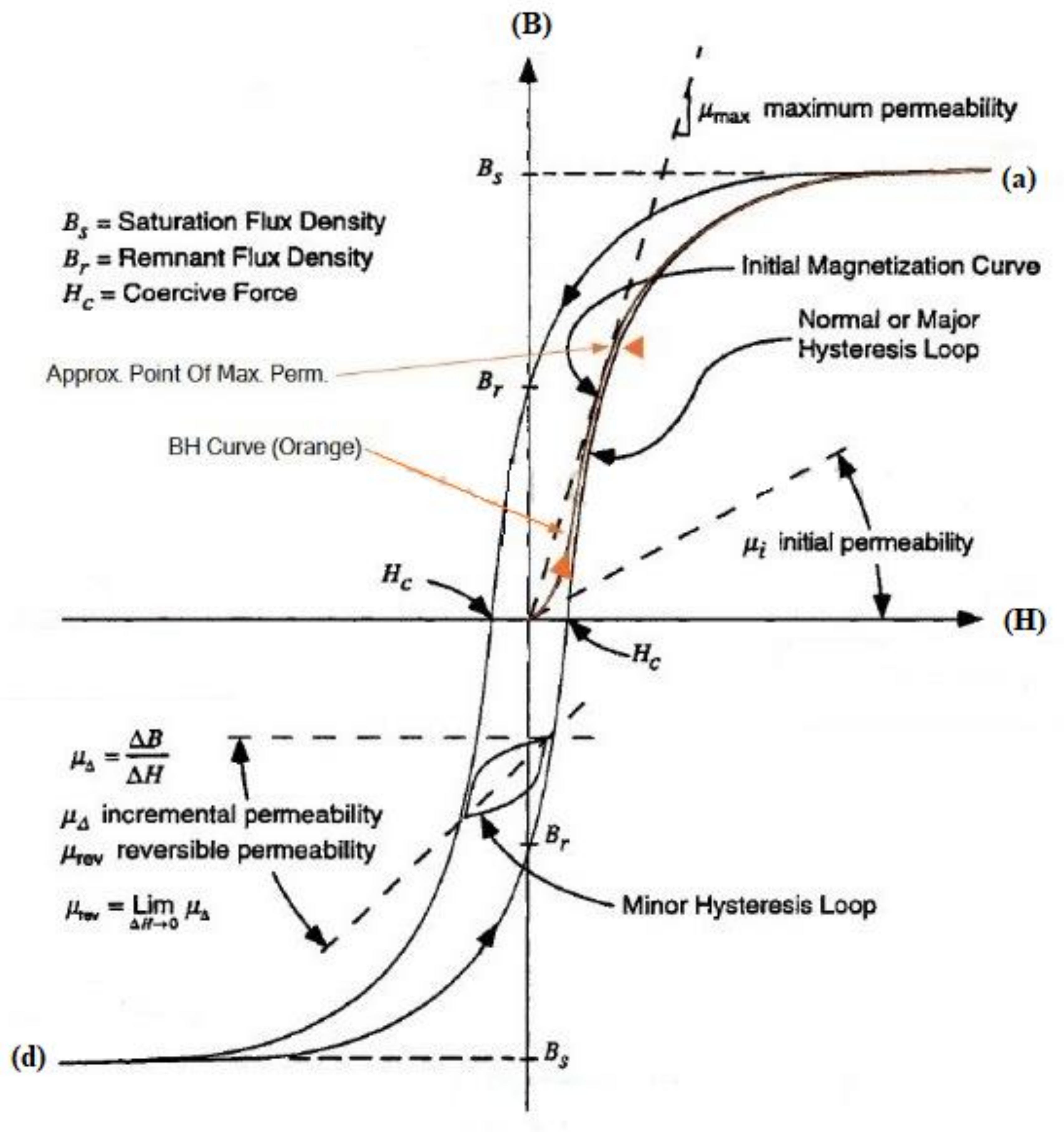
In Figure 9, as the magnetic field increases initially, the magnetization is reversible until reaching a specific threshold. Beyond this point, further increases in the magnetic field lead to irreversible magnetization. Point “a” on the loop represents saturation induction, indicating that additional increases in the magnetic field will have minimal impact on the magnetic flux density. When the magnetization is reduced to zero from point “a”, some magnetism remains in the material, which is known as remanence.
Subsequently, if the magnetic field is applied in the opposite direction, it reaches point “Hc”, which is known as coercivity. Coercivity represents the level of magnetic field intensity required to reset the magnetization back to zero. Point “d” represents the saturation flux density in the negative direction. This cyclic loop formed by these points is commonly referred to as a hysteresis loop.

6.2.2. Eddy Current Loss

The generation of eddy currents in the core results in resistive loss. The magnitude of this loss is inversely proportional to the resistance of the core material. One effective way of mitigating eddy current loss is by laminating the core material. Lamination involves using thin sheets of the core material, which helps reduce the flow of eddy currents.
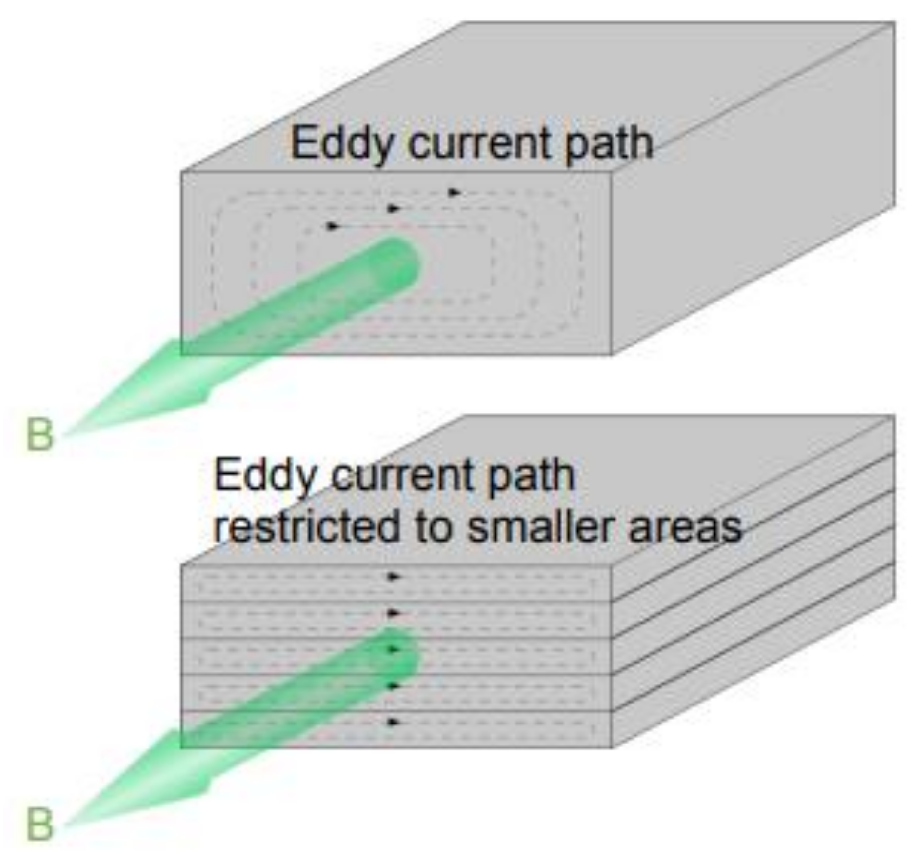
According to Faraday’s law, an adjustment in the magnetic field induces a counteracting electromotive force (emf). For of this induced emf, currents are produced within the core that do not contribute to the useful output power; instead, they dissipate as heat. This phenomenon is known as eddy current loss is a significant portion of total energy loss in electrical devices. To minimize eddy currents, various approaches can be employed, such as using thinner laminated sheets, increasing the silicon content, and reducing the grain size. Thinner laminations confine the flow of electrons within the layers, preventing the formation of wider current loops, as depicted in Figure 10.
While reducing the thickness of the core material seems advantageous with respect to minimizing eddy current loss, there are some drawbacks to consider. Thinner sheets can lead to instability in secondary-recrystallization behaviour, and the decrease in sheet thickness can also contribute to higher hysteresis loss due to increased surface roughness, resulting in more overall loss [58]. Therefore, finding an optimal thickness is essential to strike the right balance.
To enhance the resistivity of steel and reduce eddy currents, it can be beneficial to increase its silicon content. For instance, Chun [59] raised the silicon content from 0.21–2% in an electrical steel, resulting in an increase in resistivity from 15–38 µΩ-cm.
Eddy currents, in the case of uniform magnetic fields, uniform materials, and no skin effect, can be calculated using Equation (1) [58].
Figure 10. Schematic diagram of the eddy currents, in the case of uniform magnetic fields [59].
Applsci 13 10283 g010

6.2.3. Anomalous Loss

At first, the discrepancy between practical loss and theoretical loss was attributed to flux harmonics, arising from the non-linear B-H relationship. However, Brailsford et al. [8] showed that flux harmonics alone could not fully account for the additional loss when modelling thin ferromagnetic laminations. To address this phenomenon, Agarwal et al. [9] introduced the concept of domain wall bowing. According to this theory, the centre of the domain wall moves more slowly than the surface, leading to a difference between practical and theoretical loss, which was termed anomalous loss.
At specific frequencies, such as 50 and 60 Hz, anomalous loss can constitute up to 50% of the total loss [60]. The magnitude of anomalous losses is influenced by the grain size of the material, with a smaller grain size leading to reduced domain width. The domain width is determined by two energies: the magnetostatic energy and the domain wall energy. Minimizing the combined effect of these energies determines the domain width, which is directly proportional to the square root of the grain size [61]. A smaller domain width means that the wall covers a shorter distance in the same amount of time, ultimately resulting in reduced wall velocity.

7. Factors Affecting Loss for Electrical Steel

The impact of these factors can be understood in relation to total loss (Pc), hysteresis loss (Ph), and eddy current loss (Pe), all of which are influenced by grain size, silicon content, and domain control.

7.1. Grain Size

Grain size plays a pivotal role in magnetic materials and can be influenced by factors like cold rolling, strengthening temperature, and time. A larger grain size tends to enhance magnetic permeability since it results in uniformly oriented domains, whose alignment requires only a small magnetic field. However, larger grain sizes also lead to wider domain wall spacing, which improves overall loss. At higher frequencies, wide domain spacing necessitates rapid movement of the domain walls to return to their initial state, causing energy dissipation when new walls are created or when bowing occurs due to the larger distance between walls. Oppositely, a smaller grain size helps mitigate anomalous losses because the velocity of domain walls is reduced, but it may result in a higher proportion of grain boundaries, which can hinder domain wall motion through pinning [62]. Striking the right balance in grain size is crucial for minimizing losses. Refining or narrowing the domains can be employed as a technique to reduce losses, and finding the optimal balance is essential to achieve loss minimization. The mechanical characteristics of steel are greatly influenced by the size of grains and precipitates. Being able to assess these features without causing damage is important. In the study, a group of researchers altered the sizes and distributions of grains and precipitates in both low-carbon steel and lab model steel [63]. They then compared different magnetic properties obtained from major and minor magnetization loops [64].

7.2. Impurity Content

Impurities are commonly detected in magnetic materials in the form of metal sulphides, carbides, or nitrides as precipitates, ranging in size from 10 to 400 nm. Notably, aluminium nitride (AlN) and manganese sulphide (MnS) precipitates act as beneficial inhibitors, facilitating preferential grain growth in the direction of easy magnetization. However, excessive precipitation can hinder domain wall movement by pinning the walls.
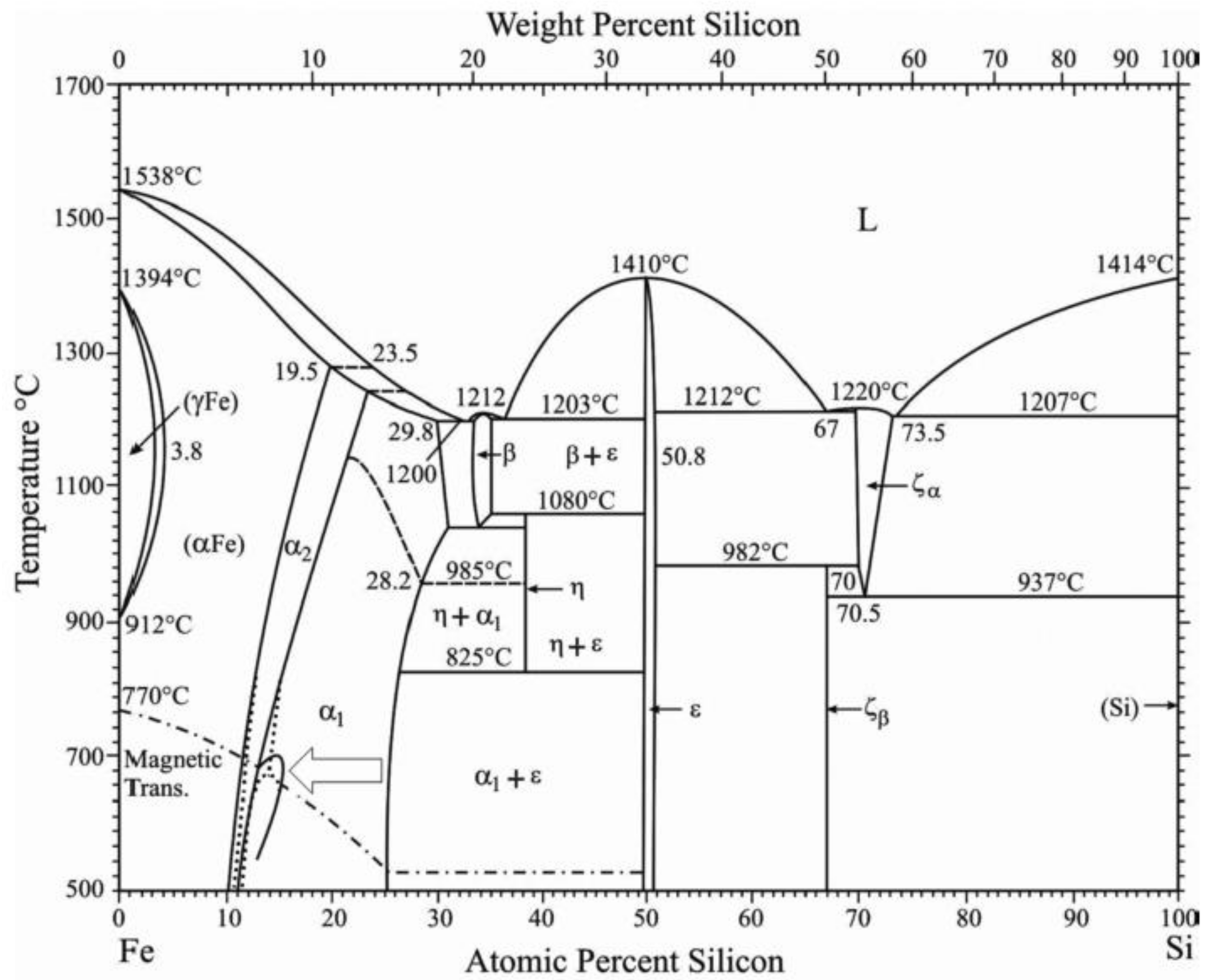
The magnetic permeability and occurrence of eddy currents are significantly influenced by the silicon content in a material. The addition of silicon modifies the A3 and A4 temperatures, creating a gamma loop at a specific silicon percentage and temperature. With further increases in silicon content, a material’s grain refinement is limited, resulting in larger grains, as depicted in Figure 11. Additionally, a higher silicon content effectively reduces eddy currents but can also affect a material’s permeability in different magnetic fields. However, higher silicon content can also lead to increased brittleness, posing challenges during the rolling process if the silicon content exceeds a certain threshold. The transformation of harmful carbides into graphite during rolling has proven to be beneficial in addressing this issue.
Carbon’s presence can be advantageous with respect to achieving a sharp crystallographic orientation with significant solid reduction. However, combining carbon with iron can lead to the formation of pearlite, which negatively impacts magnetic properties and results in undesired products. Moreover, if carbon is present in the solid solution, it may precipitate over time through a process called magnetic machinability. This process affects domain wall motion and, consequently, increases losses [60].

7.3. Soft Magnetic Materials

Soft magnetic materials are highly desirable due to their easy magnetization and low coercive fields, making them ideal for use in the cores of rotating electrical machines and transformers. To assess the performance of such materials, a key figure of merit is the relative permeability (µr), which indicates a material’s responsiveness to an applied magnetic field. Coercivity and saturation magnetization are two other critical parameters of interest, and they are determined by the hysteresis loop characteristics. An ideal soft magnetic material should exhibit a hysteresis loop with a small area, as this is directly proportional to the losses incurred in the material.

7.4. Hard Magnetic Materials

These materials possess remarkable stability and can serve as a permanent source of a magnetic field without being affected by external influences. They are characterized by a broad hysteresis loop, which can take on various shapes. Within this context, two crucial quantities come into play: remanent magnetization (remanence, Mr) and coercive field (Hc).

7.4.1. Remanence

Remanence is an intrinsic property that signifies the ability of a ferromagnetic material to retain a spontaneous degree of magnetization even in the absence of external magnetic fields or actions.

7.4.2. Coercive Field

A coercive field refers to the magnetic field strength needed to reduce the degree of magnetization from its remanent value to zero. It provides an indication of the magnitude of the magnetic fields that must be applied to a material to reverse its magnetization. Based on the values of these parameters, materials can be categorized into soft and hard magnetic materials [61].

7.5. Impact of Harmonics

Harmonics play a pivotal role in shaping the magnetic properties of electrical steel, exerting a notable influence on its behaviour and efficiency. When harmonics are introduced into electrical systems, they initiate a cascade of effects that ripple through a material. These effects are closely linked, creating a web of interconnected alterations in the steel’s magnetic characteristics. At the heart of this phenomenon lies the increased energy losses incurred due to non-sinusoidal currents [66]. These losses are intricately tied to the emergence of eddy currents within the material. As harmonics distort the regular current flow, eddy currents circulate within the steel, generating localized heat and, consequently, dissipating energy. Additionally, the rapid and irregular changes in the magnetic field, induced by harmonics, lead to heightened hysteresis losses. The steel’s magnetic domains struggle to align with the swiftly changing field, inducing friction-like losses as they realign. Furthermore, the material’s magnetic permeability undergoes shifts under the influence of harmonics, altering its capacity to channel magnetic flux effectively [67]. This can disrupt the functioning of devices reliant on stable magnetic properties. Notably, harmonics can even trigger the premature saturation of the material’s core, curbing its ability to handle expected magnetic field strengths. This effect could lead to compromised performance and potential overheating. Overall, the intricate shift between harmonics and electrical steel’s magnetic properties underscores the need for careful consideration and mitigation strategies in design and operation. By addressing these linked alterations, the efficiency and reliability of electrical systems can be effectively enhanced in the presence of harmonics [68].

8. The Effect of Alloying Elements on Electrical Steel

The addition of alloying elements can bring about modifications in the mechanical and chemical properties of steel. Alloys are frequently employed to tailor the characteristics of steel, making it more adaptable and advantageous for various applications. Steel, composed of a combination of carbon and iron, offers numerous benefits, including enhanced corrosion resistance and increased strength when alloyed with other elements. These advantages will be further detailed in the subsequent subsections [69].

8.1. Effect of Aluminium

The addition of aluminium (and silicon) to steel results in increased electrical resistance, leading to reduced energy loss in electrical appliances. Moreover, there is a positive impact on narrowing the magnetic properties of the steel. However, the drawback of these additives is that they make a steel extremely brittle and are challenging to process through conventional thermal-mechanical methods. To address this issue, the authors of one study developed an innovative processing technique in which the rolling of the fragile steel sheet was avoided. This process involves hot dipping the solid steel in a pure aluminium bath, followed by the diffusion treatment of the steel [70].
In the study conducted in [71], it was discovered that using silicon as a diffusant can effectively reduce power loss in non-oriented silicon iron. However, some issues were observed, such as an uneven distribution of aluminium on the surface, affecting both content and thickness penetration. The method of diffusion also had a slight influence on the anisotropy constants, potentially introducing the right amount of internal stress [72]. One significant drawback of this method is the creation of a permeable material on the steel’s side. To address this concern and regulate the amount of diffusant permeating the steel sheet, several measures can be implemented. These measures include restricting the number of diffusants, adjusting the structure and depth of the paste, or creating a suitable paste to ensure that a sufficient excess of diffusant is always available. Additionally, controlling the resistivity gradient along the thickness of the sheet may further enhance the steel’s performance under distorted magnetization conditions [72].
Aluminium is often added to electrical steels to improve their magnetic properties. In one study, an increase in aluminium content resulted in improved electrical resistance and caused changes in the resulting material’s properties. However, magnetic properties, such as magnetic core loss and magnetic permeability, were not significantly affected. Alloys with aluminium concentrations higher than 1% showed the best magnetic properties, with a core loss of about 3.5 W/kg (at 1.5 Tesla and 60 Hz) and permeability close to 4000 g/Oe (at 1.5 Tesla and 60 Hz) [73].
It was observed that a higher aluminium content in the steel led to lower magnetic flux density (B50), while the B50/Bs ratio remained constant at about 0.84 for all aluminium fractions. The decrease in B50 was attributed in samples with high aluminium content, there was a reduction in the saturation magnetization density (Bs). The maximum permeability also decreased with increasing aluminium content, and the highest permeability appeared at higher external magnetic fields for aluminium proportions greater than 6.54% by weight. The average grain size decreased with increasing aluminium content, while the texture was not significantly affected [74].

8.2. Effect of Silicon–Iron (Si Fe)

The most-used materials in electrical machines are iron alloys with a certain silicon content. These materials are available in two states: a Grain-Oriented (GO) state, which exhibits anisotropic properties with different permeabilities in different directions, and a non-oriented state, wherein magnetic properties are isotropic in all directions [75]. The addition of silicon to iron makes mechanical processing more challenging and increases electrical resistance. Sadly, this comes at a cost, as there is a slight decrease in saturation magnetization along with reduced permeability [76]. Similarly, aluminium also increases electrical resistance and further reduces a material’s permeability.
A higher manganese content in an alloy results in larger grains and, consequently, increased permeability. However, this also leads to higher losses [77].
Currently, the focus in relation to Si Fe steels is primarily on reducing iron losses, and this is driven by the need to address higher base frequencies due to increased machine speed and the presence of increased harmonics. These trends aim to improve the overall efficiency and performance of electrical machines.

High-Silicon-Content Non-Oriented Si Fe

Silicon-containing layers were developed to increase the electrical resistance of a material and thus reduce the eddy current. At present, the silicon content of these slats reaches 6.5%. However, in addition to reducing the maximum flux density and permeability of high-SiFe material, the silicon content makes alloys brittle and harder, resulting lead to increased manufacturing processes and costs and a need for more complex and expensive tools [78]

8.3. Effect of Cobalt–Iron (Co Fe)

Co-Fe alloys tend to be more expensive due to their high cobalt content. However, when combined with iron, cobalt exhibits the highest magnetization of all materials at room temperature, achieving 2.43 tesla for co-alloys with 35% and 65% iron proportions [79]. Typically, the Co content in these alloys ranges between 15% and 49% and often includes around 2% Vanadium.
The mechanical strength and magnetic properties of Co-Fe alloys can be controlled by adjusting the ratio of cobalt to iron content in a material [79]. Additionally, further enhancements can be achieved by mixing Niobium into a material or by adjusting the temperature cycle during the annealing process, which can range from 750 °C to 950 °C [80,81]. Lower annealing temperatures are advantageous for improving the mechanical properties of a material, while higher temperatures result in larger grain sizes and, consequently, improved magnetic properties [82].

8.4. Effect of Nickel–Iron (Ni Fe)

Typically, electrical machines utilize Ni-Fe alloys with a nickel content ranging from 40% to 50%. Higher nickel content leads to increased permeability in these alloys. However, it is essential to consider that higher nickel content also results in higher electrical conductivity and, consequently, greater eddy current losses [83].
To achieve optimal magnetic properties in NiFe alloys, a high-temperature annealing process exceeding 1100 °C is required along with the introduction of a surface oxide layer to develop desirable magnetic characteristics.
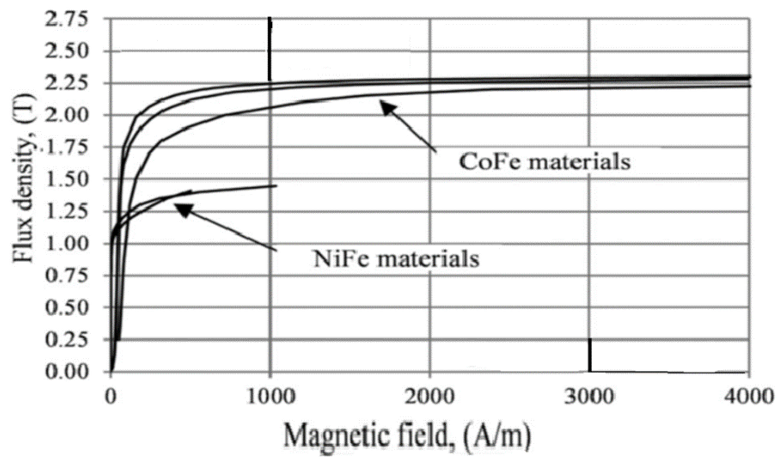
NiFe alloys containing approximately 45% to 50% nickel are commonly used in electrical machines for which low losses are prioritized, such as dental and surgical instruments operating in precisely controlled thermal environments. These alloys also find applications in aerospace devices for low-loss and non-driving components, such as analysers [84]. Figure 12 provides a comparison of the initial BH magnetization curves between typical lamination alloys (with a thickness of 0.35 mm) and alloys with 50% NiFe and 50% CoFe.
The advantages of high permeability and large resistivity in Ni-Fe alloys are further demonstrated in Figure 13, which presents iron losses for the same materials at a frequency of 400 Hz.

8.5. Effect of Manganese

Manganese (Mn) is a beneficial element in alloys as it effectively increases electrical resistance, leading to reduced losses. It is essential to maintain low sulphur content to avoid the unwanted precipitation of MnS, enabling Mn to remain in a solid solution [85]. In S-free steel materials, Mn additives ranging from 0.25% to 0.64% by weight result in linearly reduced losses (approximately 2.40 W/Mn wt%) and increased permeability and grain development. Studies have shown that electrical steels with 0.3% to 1.25% wt% Mn in Si-free steels exhibit improved magnetic properties, but higher Mn content leads to smaller grains, which, in turn, led to a deterioration in magnetic losses [86]. In ultra-low S grades with 0.5% wt% Si, the precipitation of MnSiN2 occurs, causing a decrease in grain size and an increase in {222} tissue components up to 0.94 wt% Mn [87].
Alloying with manganese has demonstrated textural improvements in alloy steels with high Si content [88]. In high-purity 0.5% wt% Si steel, adding 1.3% wt% Mn results in a decrease in core loss and a slight increase in magnetic induction [89]. However, in 3.0% wt% Si steels, higher Mn content (up to 2.0 wt%) leads to a decrease in magnetic induction and an increase in core loss [90]. Yield strength increases through solid solution strengthening at a rate of around 33 MPa/1 wt% Mn, but it is important to control S content as increased S content adversely affects material properties at each manganese level [91]. To keep Mn in solid solution and prevent Mn precipitations such as oxides and sulphides, very low S and O proportions are essential for Mn-alloyed electrical steels.
The overall impact of Mn on alloy steels with high silicon content is still a subject of debate due to contradictory findings, especially with respect to steels with low levels of damping elements. In high-alloy steel sheets, manganese increases electrical resistance by approximately 0.062 μΩm/1 wt%Mn, leading to decreased losses at frequencies above 100 Hz due to reduced dynamic iron losses [85].
Numerous research studies have explored how manganese affects high silicon sheet electric steels with different levels of manganese (0.20%, 0.69%, and 1.38% wt%). The findings indicate that the addition of manganese offers several advantages: it reduces grain size, enhances electrical resistance, and lowers core losses at higher frequencies [91]. To achieve improved magnetic properties, the optimal range of manganese concentrations lies between 0.3% and 1.5% wt% in electrical steel [92]. However, surpassing this range results in undesired effects, such as smaller grains and increased magnetic losses. Interestingly, higher concentrations of manganese lead to a notable reduction in core loss and a slight increase in magnetic flux density [85]. These insights are crucial for optimizing the composition of electrical steels to meet specific industrial and electrical needs.
In another study, it was demonstrated that manganese could diffuse into steel from a paste containing powdered manganese in a diluted silicone oil solution. The addition of manganese resulted in a remarkable reduction of up to 8% in power loss at 1.5 T in non-oriented 2.4 wt% silicon iron. This reduction can be attributed to a straightforward increase in resistivity. These findings highlight the potential of manganese as an effective element for enhancing the magnetic properties of no SiFe materials [93].

8.6. Top of Form

Effect of Phosphorus

Tanaka and Yashiki [85] conducted a study to examine the impact of phosphorus on magnetic properties and the texture of crystallization. The results showed that the addition of phosphorus led to an increase in magnetic induction, and high-phosphorus steel exhibited a slight decrease in magnetic induction with an increasing deficiency in cold rolling. In materials undergoing recrystallization, the strength of high-phosphorus steel with a (111) (112) texture is lower compared to that of low-phosphorus steel. These texture variations correspond to the changes in magnetic induction resulting from the addition of phosphorus. The recrystallization of high-phosphorus steel without separation treatment closely resembles that of low-phosphorus steel. Thus, it was inferred that the separation of phosphorus within the primary grains plays a crucial role in controlling the crystallization texture [92].

8.7. Effect of Chromium

Research on Fe-6.5% Si alloys manufactured through hot-rolling and warm-rolling has explored the impact of chromium additives on microstructure, desired phase, and magnetic properties. The findings indicate that the inclusion of chromium effectively reduces the size of the alloy bead, leading to a decrease in extraction density with increasing chromium content. The required amount of the phase in the alloys was also reduced by 1.0 wt%. Despite these changes, the magnetic properties of the alloy with chromium were not negatively affected [92].
In another study by Komatsubara et al. [94], an innovative magnetic material was developed for high-frequency appliances and compared with straight electrical steel and 6.5% Si steel. This new material exhibited remarkably low iron loss at high frequencies above 5 kHz similar to that of 6.5% Si steel. This low iron loss was achieved by increasing electric resistivity or decreasing eddy current loss. Typically, increasing the resistivity of steels results in increased brittleness and reduced workability. However, this new material contributed to its satisfactory workability thanks to the addition of chromium. Additionally, the material demonstrated favourable pulse response properties and excelled in applications for power electronic devices, particularly for active filters operating at 15 kHz.

8.8. Effect of Tin

The impact of adding Sn on the core loss and texture of non-oriented electrical steel (NOES) was thoroughly investigated in [95]. In NOES, iron loss includes both hysteresis loss and eddy current loss, with hysteresis loss being a significant contributor to power loss. Efforts were made to improve material crystalline texture with the aim of reducing hysteresis loss and increasing magnetic flux density and permeability [76]. The study revealed that Sn plays a significant role in improving a material’s crystalline texture.
According to the study conducted in [96], grain size is influenced by the presence of Sn, which hinders grain growth. The addition of Sn leads to improvements in magnetic properties, resulting in reduced core loss and increased magnetic flux density. However, when more than 0.1 wt% Sn is added, the core loss starts to increase, which contrasts with the effect observed when less than 0.1 wt% Sn is added. The enhancement of magnetic properties due to the addition of Sn correlates with the improvement in crystalline texture facilitated by the addition of Sn [97,98].
Each element carries distinct advantages and drawbacks, playing a pivotal role in guiding the optimization of electrical steel for a wide range of applications, as illustrated in Table 2.

9. The Production and Advancement of Electrical Steels

Electrical steels (Fe-3wt. %Si) find widespread applications in the cores of transformers, generators, and motors. Figure 14 illustrates the evolution of electrical steel throughout the twentieth century. The journey of electrical steel began with Hadfield’s production of 3% silicon steel in 1903, which had a notable impact on reducing losses [51]. Over time, advancements in material processing led to a reduction in the impurity content in steel, resulting in improved magnetic properties. Additionally, the introduction of the cold-rolling process played a crucial role in further reducing the thickness of materials while simultaneously enhancing their magnetic properties.
In 1934, Goss expanded upon the findings of Beck and Ruder [99], making a significant discovery about the magnetic properties of iron in specific crystallographic directions and planes. This discovery paved the way for the development of a unique type of steel with grains arranged in a manner that aligned the [100] direction parallel to the rolling direction, while the [110] planes were parallel to the sheet’s surface. The production process for this steel involved several stages, including cold reduction, intermediate annealing, decarburization, batch annealing, and flattening. The resulting steel, known as Goss-textured steel or GO steel, presented a remarkable texture known as the “Goss texture”. This particular texture, along with the favourable magnetic properties it conferred, proved to be highly advantageous for modern-day electrical steel production. As a result, GO steel has become widely used in various applications within the electrical industry.
In 1994, Nippon Steel introduced a novel high-permeability steel called HiB [54]. In contrast with Goss steel, the manufacturing process for HiB steel involved just one cold-rolling reduction. The key inhibitors used during production were AlN as the primary inhibitor and manganese sulphide (MnS) as the secondary inhibitor. These inhibitors played a crucial role in enhancing the magnetic properties of the steel. While the angle of orientation with the rolling direction was reduced from 7° to 3° compared to Goss steel, there was a trade-off. The grain size of the HiB steel increased significantly from 0.3 mm to 1 cm [100]. Despite the larger grain size, the HiB steel exhibited high permeability, making it a promising choice for various applications where magnetic efficiency is essential.
Driven by the increasing demand for improved efficiency, new domain refining techniques were developed, such as laser scribing introduced by Nippon Steel [46]. The losses achieved using this method were 0.85 W/kg when exposed to a magnetic flux density of 1.7 T, with a sheet thickness of 0.23 mm. These losses were found to be 5–8% lower compared to the losses obtained for unscratched HiB steel [101]. However, it was observed that the laser used in this technique caused surface damage to the steel. To address this issue, a recoating process was required to repair the damaged surface since the original coating vaporized during the laser treatment. Other methods, like creating grooves on the steel and depositing a ceramic coating, have also been employed to refine domains and apply tension on the GOES substrate [73].

10. Influence of Coating on Electrical Steel

Researchers are actively working to improve the performance of electrical steels through several approaches. These include advancements in secondary recrystallization techniques [72], the precise control of grain orientation [11], increasing electrical resistivity, gauge reduction [79], and gaining a deeper understanding of the magnetic domain structure [102]. These efforts aim to optimize the magnetic and electrical properties of electrical steels, making them more efficient and suitable for a wide range of applications in the electrical and electronics industries [103]. Among these approaches, utilizing effective stress coatings has shown promising results in minimizing losses and magnetostriction [82].
During transformer manufacturing, steel sheets are typically under stress-free conditions, but compressive stress can develop during the process, leading to increased magnetostriction. By applying coatings that induce tensile stress on the steel, the compressive stress can be counterbalanced. Coatings play a crucial role in reducing power losses. By manipulating the surface roughness or varying surface stress through coatings, overall power loss can be significantly decreased [83]. Studies have shown that improving surface roughness can reduce power losses by 30–40% [84]. Coatings play a crucial role in minimizing eddy current losses in electrical steels through various mechanisms. By providing insulation resistance, coatings effectively reduce the flow of eddy currents, which are electric currents induced in a material via changing magnetic fields. Additionally, coatings help to decrease hysteresis and anomalous losses by enhancing surface roughness. The rougher surface introduced by the coating alters the magnetic domain structure, leading to reduced energy losses during magnetization cycles. Moreover, coatings can introduce beneficial tensile stress to a substrate, further optimizing a material’s magnetic properties and enhancing its overall performance [43]. In this way, coatings contribute significantly to the efficiency and effectiveness of electrical steels in various electrical and electronic applications. Moreover, the application of tensile stress through coatings to a steel sheet can bring further benefits. Also, this process helps eliminate surface closure domains, which results in a narrowing of domain wall spacing and reduces anomalous loss. Additionally, by removing supplementary structures, the coercivity of the magnetic material can be reduced, leading to an improvement in hysteresis loss [82].
Several techniques are available for applying coatings to steel sheets, each with its own unique advantages. These methods include sol–gel processes, chemical vapor deposition (CVD), physical vapor deposition (PVD), plasma spraying, wet coating, printing, electroless plating, and electrochemical plating. The corresponding coatings are designed to possess specific properties to meet the desired requirements for electrical steels. These properties include insulation resistance, which prevents the flow of an electric current; heat resistance; chemical resistance to withstand harsh environments; it possessed the capability to be easily punched, simplifying the processing of the material; weldability for joining; corrosion resistance to prevent degradation; burn-out characteristics; and resistance to compression. The thickness of the coating, surface roughness, and scratch resistance are also crucial factors to consider when applying coatings to ensure optimal performance [104].
For example, a 1 µm thick titanium carbide (TiC) coating deposited via chemical vapor deposition on 0.23 mm thick GOES effectively reduced losses to 0.586 W/kg [105]. The coating primarily reduces eddy current loss, while hysteresis loss remains unaffected. Combining the effects of surface roughness and tensile stress, Nishiike et al. [106] achieved a loss of 0.6 W/kg. By chemically polishing GOES to a surface roughness of 0.05 µm and applying a tensile stress of 45 MPa, the authors observed an increase in the number of mobile domain walls, thereby reducing eddy current loss. The application of tensile stress had different effects at different levels: below 10 MPa, it reduced domain size, while above 10 MPa, it improved the electrical steel’s performance through magnetization rotation in the rolling direction [107].

11. Conclusions

  • Microstructure’s Impact on Magnetic Properties:
The intricate relationship between the microstructures and magnetic properties in electrical steels has been a focal point of this review. Advances in microscopy techniques have enabled a deeper understanding of how grain boundaries, crystallographic orientations, and defects influence magnetic behaviour. Recognizing the profound impact of microstructure allows researchers and engineers to tailor electrical steel compositions and processing methods for optimal performance in specific applications.
2.
Efficiency Enhancement through Loss Analysis:
Losses within electrical steels significantly affect the efficiency of electrical systems. Through sophisticated loss analysis methods, encompassing both hysteresis and eddy current losses, we have gained insights into the energy dissipation mechanisms within these materials. The pursuit of enhanced energy efficiency requires a continuous focus on minimizing losses via refined material design and processing techniques.
3.
Alloying Elements’ Role in Magnetic Customization:
The magnetic properties of electrical steels are intimately linked with their alloying elements and chemical compositions. Our exploration into these relationships, including the influence of silicon, aluminium, and specialized texturing, underscores the potential for tailoring magnetic characteristics. Precision in alloy composition presents avenues for fine-tuning magnetic permeability, coercivity, and saturation flux density, aligning materials more closely with application demands.
4.
Coatings: Dual-function Enhancements:
The evolving landscape of electrical steels recognizes coatings as dual-function components. Not only do coatings shield against environmental degradation, but they also exert an influence on magnetic properties. Recent developments in coating technologies, encompassing insulating layers and thin films, have marked a paradigm shift in improving electrical steel performance. This synthesis of protection and controlled magnetic influence opens doors to broader application possibilities.
In summation, this comprehensive review underscores the interwoven nature of microstructure, loss analysis, magnetic properties, alloying elements, and coatings in shaping the realm of electrical steels. Delving into each facet uncovers the intricacies that collectively define material performance. As technology and energy systems continue to advance, the insights garnered from this study will fuel the ongoing progress of tailored electrical steel designs across diverse applications.

12. Future Research Directions and Identifying Research Gaps

As we conclude this study on electrical steels, it is important to highlight the areas where further research is needed and identify the gaps in our current understanding. By addressing these research lacunas, we can pave the way for future investigations that will contribute to a more comprehensive understanding of electrical steels and their applications.
Dynamic Behaviour under Variable Conditions: While much has been explored about the static properties of electrical steels, their behaviours under varying environmental and operational conditions remains less explored. Investigating how electrical steels respond to dynamic loading, temperature fluctuations, and exposure to different gases or liquids can provide valuable insights into their long-term performance.
Multi-Scale Modelling and Simulation: The integration of advanced modelling techniques, such as multi-scale simulations, can bridge the gap between microstructural features and macroscopic properties. Developing accurate models that consider various length scales will help in predicting materials’ behaviours more precisely, aiding in design optimization and performance prediction.
Emerging Coating Technologies: While coatings have shown promise in enhancing electrical steel properties, their long-term performance and interactions with different environments require deeper investigation. Understanding the mechanisms behind these coatings and their effects on material behaviour over time can lead to more effective and durable solutions.
Advanced Characterization Techniques: As new characterization methods emerge, their application to studying electrical steels can provide a wealth of information. Techniques like in situ microscopy, advanced diffraction methods, and high-resolution imaging can offer insights into electrical steels behaviours under specific conditions.
Tailoring for Specific Applications: Electrical steels find applications in diverse fields, each with unique requirements. Tailoring electrical steels to meet the specific demands of applications like electric vehicles, renewable energy systems, and high-frequency devices requires a deeper understanding of how different material properties influence performance in these contexts.
By addressing these research gaps and focusing on the aforementioned directions, future studies can contribute significantly to the advancement of electrical steel technology. These investigations will not only expand our understanding of material properties but also drive innovation, resulting in more efficient and effective electrical steel materials for a wide range of applications.

Author Contributions

Conceptualization, E.E. and F.A.; methodology, E.E.; software, E.E.; validation, E.E. and F.A.; formal analysis, E.E.; investigation, E.E.; resources, E.E.; data curation, E.E.; writing—original draft preparation, E.E.; writing—review and editing, E.E.; visualization, F.A.; supervision, E.E.; project administration, F.A.; funding acquisition, F.A. All authors have read and agreed to the published version of the manuscript.

Funding

This research received no external funding.

Institutional Review Board Statement

Not applicable.

Informed Consent Statement

Not applicable.

Data Availability Statement

Not applicable.

Acknowledgments

The authors would like to thank Cardiff University/School of Engineering for accepting to pay the APC towards publishing this paper.

Conflicts of Interest

The authors declare no conflict of interest.

References

  1. Hayakawa, Y. Electrical Steels. Encycl. Mater. Met. Alloys 2021, 2, 208–213. [Google Scholar] [CrossRef]
  2. Du, Y.; O’Malley, R.J.; Buchely, M.F.; Kelly, P. Effect of rolling process on magnetic properties of Fe-3.3 wt% Si non-oriented electrical steel. Appl. Phys. A Mater. Sci. Process. 2022, 128, 765. [Google Scholar] [CrossRef]
  3. Herrmann, H.; Bucksch, H. Saturation Magnetization. In Dictionary Geotechnical Engineering/Wörterbuch GeoTechnik; Springer: Berlin/Heidelberg, Germany, 2014; p. 1170. [Google Scholar] [CrossRef]
  4. Walter, J.L. Secondary Recrystallization. Texturen Forsch. Prax. Textures Res. Pract. 1969, 227–251. [Google Scholar] [CrossRef]
  5. Verbeken, K.; Infante-Danzo, I.; Barros-Lorenzo, J.; Schneider, J.; Houbaert, Y. Innovative processing for improved electrical steel properties. Rev. Metal. 2010, 46, 458–468. [Google Scholar] [CrossRef]
  6. Gervasyeva, I.V.; Milyutin, V.A.; Mineyev, F.V.; Babushko, Y.Y. Assessment of the Textured State of the Nonoriented Electrical Steel for Electromobiles and the Effect of the Texture on the Basic Magnetic Characteristics. Phys. Met. Metallogr. 2020, 121, 618–623. [Google Scholar] [CrossRef]
  7. Coombs, A.; Lindenmo, M.; Snell, D.; Power, D. Review of the types, properties, advantages, and latest developments in insulating coatings on nonoriented electrical steels. IEEE Trans. Magn. 2001, 37, 544–557. [Google Scholar] [CrossRef]
  8. Ros-Yanez, T.; De Wulf, M.; Houbaert, Y. Influence of the Si and Al gradient on the magnetic properties of high-Si electrical steel produced by hot dipping and diffusion annealing. J. Magn. Magn. Mater. 2004, 272–276, 2003–2004. [Google Scholar] [CrossRef]
  9. Ren, Q.; Hu, Z.; Cheng, L.; Zhang, L. Effect of rare earth elements on magnetic properties of non-oriented electrical steels. J. Magn. Magn. Mater. 2022, 560, 169624. [Google Scholar] [CrossRef]
  10. Du, Y.; O’Malley, R.; Buchely, M.F. Review of Magnetic Properties and Texture Evolution in Non-Oriented Electrical Steels. Appl. Sci. 2023, 13, 6097. [Google Scholar] [CrossRef]
  11. Hong, J.; Choi, H.; Lee, S.; Kim, J.K.; Koo, Y.M. Effect of Al content on magnetic properties of Fe-Al Non-oriented electrical steel. J. Magn. Magn. Mater. 2017, 439, 343–348. [Google Scholar] [CrossRef]
  12. Ouyang, G.; Chen, X.; Liang, Y.; Macziewski, C.; Cui, J. Review of Fe-6.5 wt%Si high silicon steel—A promising soft magnetic material for sub-kHz application. J. Magn. Magn. Mater. 2019, 481, 234–250. [Google Scholar] [CrossRef]
  13. Shin, J.S.; Bae, J.S.; Kim, H.J.; Lee, H.M.; Lee, T.D.; Lavernia, E.J.; Lee, Z.H. Ordering-disordering phenomena and micro-hardness characteristics of B2 phase in Fe-(5–6.5%)Si alloys. Mater. Sci. Eng. A 2005, 407, 282–290. [Google Scholar] [CrossRef]
  14. Boehm, L.; Hartmann, C.; Gilch, I.; Stoecker, A.; Kawalla, R.; Wei, X.; Hirt, G.; Heller, M.; Korte-Kerzel, S.; Leuning, N.; et al. Grain size influence on the magnetic property deterioration of blanked non-oriented electrical steels. Materials 2021, 14, 7055. [Google Scholar] [CrossRef] [PubMed]
  15. Petryshynets, I.; Kováč, F.; Petrov, B.; Falat, L.; Puchý, V. Improving the magnetic properties of non-oriented electrical steels by secondary recrystallization using dynamic heating conditions. Materials 2019, 12, 1914. [Google Scholar] [CrossRef] [PubMed]
  16. Moses, A.J. Energy efficient electrical steels: Magnetic performance prediction and optimization. Scr. Mater. 2012, 67, 560–565. [Google Scholar] [CrossRef]
  17. Moses, T. Opportunities for exploitation of magnetic materials in an energy conscious world. Interdiscip. Sci. Rev. 2002, 27, 100–113. [Google Scholar] [CrossRef]
  18. Leuning, N.; Steentjes, S.; Hameyer, K. Effect of grain size and magnetic texture on iron-loss components in NO electrical steel at different frequencies. J. Magn. Magn. Mater. 2019, 469, 373–382. [Google Scholar] [CrossRef]
  19. Lee, H.H.; Jung, J.; Yoon, J.I.; Kim, J.K.; Kim, H.S. Modelling the evolution of recrystallization texture for a non-grain oriented electrical steel. Comput. Mater. Sci. 2018, 149, 57–64. [Google Scholar] [CrossRef]
  20. Goss, N.P. New Development in Electrical Strip Steels Characterized by Fine Grain Structure Approaching the Properties of a Single Crystal. Trans. Amer. Soc. Metals 1935, 23, 511–531. [Google Scholar]
  21. Yue-Lin, L.; Ying, Z.; Rong-Jie, H.; Guang-Hong, L. Study of the theoretical tensile strength of Fe by a first-principles computational tensile test. Chinese Phys. B 2009, 18, 1923–1930. [Google Scholar] [CrossRef]
  22. Ye, T.; Lu, Z.; Ma, C. Evolution of Microstructure and Texture with the Low-Silicon in Non-Oriented Silicon Steel. IOP Conf. Ser. Earth Environ. Sci. 2018, 170, 042086. [Google Scholar] [CrossRef]
  23. IEC 60404-2; Magnetic Materials—Part 2: Methods of Measurement of the Magnetic Properties of Electrical Steel Strip and Sheet by Means of an Epstein Frame. International Electrotechnical Commission: Geneva, Switzerland, 2008.
  24. Siovert, J.D. Determination of AC magnetic power loss of electrical steel sheet: Present status and trends. IEEE Trans. Magn. 1984, 20, 1702–1707. [Google Scholar] [CrossRef]
  25. Marketos, P.; Zurek, S.; Moses, A.J. Calculation of the mean path length of the Epstein frame under non-sinusoidal excitations using the double Epstein method. J. Magn. Magn. Mater. 2008, 320, 2542–2545. [Google Scholar] [CrossRef]
  26. Leuning, N.; Steentjes, S.; Stöcker, A.; Kawalla, R.; Wei, X.; Dierdorf, J.; Hirt, G.; Roggenbuck, S.; Korte-Kerzel, S.; Weiss, H.A.; et al. Impact of the interaction of material production and mechanical processing on the magnetic properties of non-oriented electrical steel. AIP Adv. 2018, 8, 047601. [Google Scholar] [CrossRef]
  27. Moses, A.J. Effects of stress on the magnetic properties of grain-oriented silicon-iron magnetized in various directions. IEEE Trans. Magn. 1981, 17, 2872–2874. [Google Scholar] [CrossRef]
  28. Ros-Yañez, T.; Houbaert, Y.; Gómez Rodríguez, V. High-silicon steel produced by hot dipping and diffusion annealing. J. Appl. Phys. 2002, 91, 7857–7859. [Google Scholar] [CrossRef]
  29. Lyudkovsky, G.; Rastogi, P.K.; Bala, M. Nonoriented Electrical Steels. JOM 1986, 38, 18–26. [Google Scholar] [CrossRef]
  30. Zhang, Y.; Cheng, M.C.; Pillay, P. A novel hysteresis core loss model for magnetic laminations. IEEE Trans. Energy Convers. 2011, 26, 993–999. [Google Scholar] [CrossRef]
  31. Chen, Y.; Pillay, P. An improved formula for lamination core loss calculations in machines operating with high frequency and high flux density excitation. In Proceedings of the Conference Record of the 2002 IEEE Industry Applications Conference, 37th IAS Annual Meeting (Cat. No.02CH37344), Pittsburgh, PA, USA, 13–18 October 2002; Volume 2, pp. 759–766. [Google Scholar] [CrossRef]
  32. Guru, B.S.; Hiziroglu, H.R. Electric Machinery and Transformers, 3rd ed.; Oxford University Press: New York, NY, USA, 2001; ISBN 9780195138900. [Google Scholar]
  33. Popovic, Z.B.; Popovic, B.D. Introductory Electromagnetics: Practice, Problems and Labs. 2000, p. 305. Available online: https://cdn.preterhuman.net/texts/science_and_technology/physics/Electromagnetic_Field_Theory/Introductory%20Electromagnetics%20-%20Z.%20Popovic,%20B.%20Popovic.pdf (accessed on 1 January 2022).
  34. Ibrahim, M.; Pillay, P. Advanced testing and modeling of magnetic materials including a new method of core loss separation for electrical machines. IEEE Trans. Ind. Appl. 2012, 48, 1507–1515. [Google Scholar] [CrossRef]
  35. Loss, W.; Oriented, G. Method for Producing a Super Low Watt Loss Grain Oriented Electrical STEEL Sheet. U.S. Patent No. 3,932,236, 13 January 1976. [Google Scholar]
  36. Yamamoto, T.; Nozawa, T. Effects of tensile stress on total loss of single crystals of 3% silicon-iron. J. Appl. Phys. 1970, 41, 2981–2984. [Google Scholar] [CrossRef]
  37. Goel, V.; Anderson, P.; Hall, J.; Robinson, F.; Bohm, S. Electroless Plating: A Versatile Technique to Deposit Coatings on Electrical Steel. IEEE Trans. Magn. 2016, 52, 8–11. [Google Scholar] [CrossRef]
  38. Moses, A.J.; Jiles, D.C. Origin, Measurement and Application of the Barkhausen Effect in Magnetic Steeltle. 2007. Available online: https://books.google.co.uk/books?hl=en&lr=&id=EmbmP6qPNxIC&oi=fnd&pg=PA4&dq=A.J.+Moses,+D.C.+Jiles,+in:+S.+Takahashi,+H.+Kikuchi+(Eds.),+Electromagnetic+Nondestructive+Evaluation,+IOS+Press,+2007,+p.+4.&ots=hGJbfUgUw5&sig=wk-DX6dBdgxqDLJ9obuJrO7lsZ8#v=one (accessed on 1 January 2022).
  39. Shilling, J.W.; Houze, G.L.; Moses, A.J.; Jiles, D.C. Electromagnetic Nondestructive Evaluation; Takahashi, S., Kikuchi, H., Eds.; IOS Press: Amsterdam, The Netherlands, 2007; p. 4. [Google Scholar]
  40. Calvillo, P.R. Deformation Analysis of High-Si-Steel during Torsion and Compression Testing. Ph.D. Thesis. 2007. Available online: http://hdl.handle.net/1854/LU-8598031%0A (accessed on 1 November 2022).
  41. Transactions, I. Magnetic properties and dynamic domain behavior in grain-oriented 3% Si-Fe(Article). IEEE Trans. Magn. 1996, 32, 572–589. [Google Scholar]
  42. Lewis, E.; Initiating, A.; Vii, S.; Halide, T.; Halide, Z.; Systems, I. High Electrical Resistivity and Permeability of Soft Magnetic Granular Alloys. Polymer 1991, 2, 10403–10411. [Google Scholar] [CrossRef]
  43. Moses, A.J. Electrical steels. Past, present and future developments. IEEE Proc. A Phys. Sci. Meas. Instrum. Manag. Educ. Rev. 1990, 137, 233–245. [Google Scholar] [CrossRef]
  44. Honda, O.; Kaya, S.; Masuyama, Y. On the magnetic properties of single crystals of iron. Nature 1926, 117, 753–754. [Google Scholar] [CrossRef]
  45. Wohlfarth, E.P.; Arrott, A.S. Ferromagnetic Materials: A Handbook on the Properties of Magnetically Ordered Substances, Vols. 1 and 2. Phys. Today 1982, 35, 63–64. [Google Scholar] [CrossRef]
  46. Gregersen, E. The Britannica Guide to Electricity and Magnetism; Firest: New York, NY, USA, 2011; Available online: https://books.google.co.uk/books?hl=en&lr=&id=ac2cAAAAQBAJ&oi=fnd&pg=PP1&ots=ijIcoJG992&sig=3t5HXFLBRqrRmlTdxn-HMEHRkig&redir_esc=y#v=onepage&q&f=false (accessed on 1 January 2023).
  47. Laughton, M.A.; Say, M.G. Electrical Engineer’s Reference Book, 4th ed.; Elsevier: Amsterdam, The Netherlands, 2013; ISBN 978-0-408-00431-2. [Google Scholar] [CrossRef]
  48. Oda, Y.; Okubo, T.; Takata, M. Recent development of non-oriented electrical steel in JFE steel. JFE Tech. Rep. 2016, 21, 7–13. [Google Scholar]
  49. Binesti, D.; Ducreux, J.P. Core losses and efficiency of electrical motors using new magnetic materials. IEEE Trans. Magn. 1996, 32, 4887–4889. [Google Scholar] [CrossRef]
  50. Zu, G.; Xu, Y.; Luo, L.; Han, Y.; Sun, S.; Miao, R.; Zhu, W.; Gao, L.; Ran, X. Effect of rolling temperature on the recrystallization behavior of 4.5 wt.% Si non-oriented electrical steel. J. Mater. Res. Technol. 2022, 17, 365–373. [Google Scholar] [CrossRef]
  51. Werner, F.E.; Jaffee, R.I. Energy-efficient steels for motor laminations. J. Mater. Eng. Perform. 1992, 1, 227–234. [Google Scholar] [CrossRef]
  52. Nakayama, T.; Honjou, N.; Nagai, A.; Yashiki, H. Non-oriented electrical steel sheets. Sumitomo Met. 1996, 48, 39–44. [Google Scholar]
  53. Hawezy, D. The influence of silicon content on physical properties of non-oriented silicon steel. Mater. Sci. Technol. 2017, 33, 1560–1569. [Google Scholar] [CrossRef]
  54. ASTM A976-18; Standard Classification of Insulating Coatings for Electrical Steels by Composition, Relative Insulating Ability and Application. ASTM International: West Conshohocken, PA, USA, 2013.
  55. Shrivastava, K.N. Flux Quantization; Springer: Dordrecht, The Netherlands, 2000; ISBN 978-94-011-7008-6. [Google Scholar]
  56. Tang, Q. Investigation of Magnetic Properties of Electrical Steel and Transformer Core at High Flux Densities; The University of Manchester: Manchester, UK, 2015; p. 92. [Google Scholar]
  57. Dey, P.K. Application of Ferrite Medium in Microwave Devices. In Proceedings of the 60th CONGRESS ISTAM Section Code: SM8, Jaipur, India, 16–19 December 2015. [Google Scholar]
  58. Heathcote, M. J & P Transformer Book, 13th ed.; Elsevier: Amsterdam, The Netherlands; London, UK; Oxford, UK, 2011; Available online: https://books.google.co.uk/books?op=lookup&id=paPKsOXn5FMC&continue=https://books.google.co.uk/books%3Fhl%3Den%26lr%3D%26id%3DpaPKsOXn5FMC%26oi%3Dfnd%26pg%3DPP1%26dq%3DM.%2BJ.%2BHeathcote,%2BThe%2BJ%2B%2526%2BP%2Btransformer%2Bbook%2B:%2Ba%2Bpractical%2Bt (accessed on 1 January 2023).
  59. Cullity, B.D.; Graham, C.D. Introduction to Magnetic Magnetic Materials, 2nd ed.; IEEE Pres&Wiley: Hoboken, NJ, USA, 2009; p. 322. [Google Scholar]
  60. Brailsford, F.; Burgess, J.M. Internal waveform distortion in silicon-iron laminations for magnetization at 50 c/s. Proc. IEEE Part C Monogr. 1961, 108, 458. [Google Scholar] [CrossRef]
  61. Agarwal, P.D.; Rabins, L. Rigorous Solution of Eddy Current Losses in Rectangular Bar for Single Plane Domain Wall Model. J. Appl. Phys. 2009, 31, S246–S248. [Google Scholar] [CrossRef]
  62. Kwun, H.; Burkhardt, G.L. Effects of grain size, hardness, and stress on the magnetic hysteresis loops of ferromagnetic steels. J. Appl. Phys. 1987, 61, 1576–1579. [Google Scholar] [CrossRef]
  63. Rezayat, M.; Karamimoghadam, M.; Moradi, M.; Casalino, G.; Roa Rovira, J.J.; Mateo, A. Overview of Surface Modification Strategies for Improving the Properties of Metastable Austenitic Stainless Steels. Metals 2023, 13, 1268. [Google Scholar] [CrossRef]
  64. Liu, J.; Wilson, J.; Davis, C.L.; Peyton, A. Magnetic characterisation of grain size and precipitate distribution by major and minor BH loop measurements. J. Magn. Magn. Mater. 2019, 481, 55–67. [Google Scholar] [CrossRef]
  65. Eisen, R. Fe–Si Iron–Silicon; Springer: Berlin/Heidelberg, Germany, 1982. [Google Scholar]
  66. Gorji Ghalamestani, S.; Vandevelde, L.; Dirckx, J.J.J.; Melkebeek, J.A.A. Magnetostriction and the influence of higher harmonics in the magnetic field. IEEE Trans. Magn. 2012, 48, 3981–3984. [Google Scholar] [CrossRef]
  67. Moses, A.J. Effects of magnetic properties and geometry on flux harmonics and losses in 3-phase, 5-limb, split-limb, transformer cores. IEEE Trans. Magn. 1987, 23, 3780–3782. [Google Scholar] [CrossRef]
  68. Yoshida, T.; Bai, S.; Hirokawa, A.; Tanabe, K.; Enpuku, K. Effect of viscosity on harmonic signals from magnetic fluid. J. Magn. Magn. Mater. 2015, 380, 105–110. [Google Scholar] [CrossRef]
  69. TAGUCHI, S. Review of the Recent Development of Electrical Sheet Steel. Tetsu-to-Hagane 1976, 62, 905–915. [Google Scholar] [CrossRef] [PubMed]
  70. Moses, A.J.; Thursby, G.J. Assessment of a novel method of improving the characteristics of electrical steels by a surface diffusion technique. J. Mater. Sci. 1983, 18, 1650–1656. [Google Scholar] [CrossRef]
  71. Anayi, F.; Moses, A.J.; Jenkins, K. Effect of aluminium diffusion into electrical steel on power loss under flux distortion conditions. J. Magn. Magn. Mater. 2003, 254–255, 36–38. [Google Scholar] [CrossRef]
  72. Ros-Yáñez, T.; Ruiz, D.; Barros, J.; Houbaert, Y. Advances in the production of high-silicon electrical steel by thermomechanical processing and by immersion and diffusion annealing. J. Alloys Compd. 2004, 369, 125–130. [Google Scholar] [CrossRef]
  73. Calvillo, P.R.; Bernárdez, P.; Houbaert, Y. Production of electrical steel by hot dipping in aluminium. Defect Diffus. Forum 2008, 273–276, 63–68. [Google Scholar] [CrossRef]
  74. Marques Marra, K.; Carneiro Marra, L.; Tadeu Lopes Buono, V. Effect of Aluminium Addition on the Magnetic Properties of a Semi-Processed Electrical Steel. Mater. Res. 2016, 19, 1162–1166. [Google Scholar] [CrossRef]
  75. Chwastek, K.; Wodzyński, A.; Baghel, A.P.S.; Kulkarni, S.V. Anisotropic properties of electrical steels. In Proceedings of the 2015 16th International Conference on Computational Problems of Electrical Engineering (CPEE), Lviv, Ukraine, 2–5 September 2015; pp. 21–23. [Google Scholar] [CrossRef]
  76. Senda, K.; Uesaka, M.; Yoshizaki, S.; Oda, Y. Electrical steels and their evaluation for automobile motors. World Electr. Veh. J. 2019, 10, 31. [Google Scholar] [CrossRef]
  77. Felix, R.; Cardoso, D.A.; Brandao, L.; Antônio, M.; De Pesquisa, C.; Acesita, S.A.; Mg, T. Influence of Grain Size and Additions of Al and Mn on the Magnetic Properties of Non-Oriented Electrical Steels with 3 wt. (%) Si 3. Mater. Res. 2008, 11, 51–55. [Google Scholar]
  78. Anon Electrical Steel Sheets. Nippon Steel Tech. Rep. 1983, 127–134.
  79. Rodewald, R.H.W. Magnetic Materials: Fundamentals, Products, Properties, Applications; Publicis: Erlangen, Germany; VAC, VACUUMSCHMELZE: Hanau, Germany, 2013. [Google Scholar]
  80. Gmbh, V.; Data, R.U.S.A.; Application, F.; Data, P. Electric Motor for Use Ina Sterilizable Dental Handpiece. U.S. Patent 8,487,488, 16 July 2013. [Google Scholar]
  81. Krings, A.; Boglietti, A.; Cavagnino, A.; Sprague, S. Soft Magnetic Material Status and Trends in Electric Machines. IEEE Trans. Ind. Electron. 2017, 64, 2405–2414. [Google Scholar] [CrossRef]
  82. Cossale, M.; Krings, A.; Soulard, J.; Boglietti, A.; Cavagnino, A. Practical Investigations on Cobalt-Iron Laminations for Electrical Machines. IEEE Trans. Ind. Appl. 2015, 51, 2933–2939. [Google Scholar] [CrossRef]
  83. ACUUMSCHMELZE GmbH & Co. KG, H. Soft Magnetic Materials and Semi-Finished Products Soft Magnetic Materials and Semi-Finished Products Contents Main Headings: 2002. Available online: https://vacuumschmelze.com/03_Documents/Brochures/PHT%20001%20en.pdf (accessed on 1 January 2023).
  84. Spaldin, N.A. Magnetic Materials. Available online: https://www.google.co.uk/books/edition/Magnetic_Materials/vnrOE8pQUgIC?hl=en&gbpv=1&dq=Material+developments.+Magn.+Technol.+Int.+16%E2%80%9319+.&pg=PR7&printsec=frontcover (accessed on 1 January 2023).
  85. Rastogi, P.K. Effect of manganese and sulfur on the texture and magnetic properties of non-oriented steel. IEEE Trans. Magn. 1977, 13, 1448–1450. [Google Scholar] [CrossRef]
  86. Liao, K.C. The effect of manganese and sulfur contents on the magnetic properties of cold rolled lamination steels. Metall. Trans. A 1986, 17, 1259–1266. [Google Scholar] [CrossRef]
  87. Yashiki, H.; Kaneko, T. Effects of Mn and S on the Grain Growth and Texture in Cold Rolled 0.5% Si Steel. ISIJ Int. 1990, 30, 325–330. [Google Scholar] [CrossRef]
  88. Kubota, T. Recent Progress on Non-oriented Silicon Steel. J. Chem. Inf. Model. 2005, 76, 1689–1699. [Google Scholar] [CrossRef]
  89. Nakayama, T.; Honjou, N.; Minaga, T.; Yashiki, H. Effects of manganese and sulfur contents and slab reheating temperatures on the magnetic properties of non-oriented semi-processed electrical steel sheet. J. Magn. Magn. Mater. 2001, 234, 55–61. [Google Scholar] [CrossRef]
  90. Ghosh, P.; Chromik, R.R.; Knight, A.M.; Wakade, S.G. Effect of metallurgical factors on the bulk magnetic properties of non-oriented electrical steels. J. Magn. Magn. Mater. 2014, 356, 42–51. [Google Scholar] [CrossRef]
  91. Schulte, M.; Steentjes, S.; Leuning, N.; Bleck, W.; Hameyer, K. Effect of manganese in high silicon alloyed non-oriented electrical steel sheets. J. Magn. Magn. Mater. 2019, 477, 372–381. [Google Scholar] [CrossRef]
  92. Tanaka, I.; Yashiki, H. Magnetic properties and recrystallization texture evolutions of phosphorus-bearing non-oriented electrical steel sheets. ISIJ Int. 2007, 47, 1666–1671. [Google Scholar] [CrossRef]
  93. Elgamli, E.; Anayi, F.; Shouran, M. Impact of manganese diffusion into non-oriented electrical steel on power loss and permeability at different temperatures. Front. Mater. 2023, 9, 1108308. [Google Scholar] [CrossRef]
  94. Komatsubara, M.; Sadahiro, K.; Kondo, O.; Takamiya, T.; Honda, A. Newly developed electrical steel for high-frequency use. J. Magn. Magn. Mater. 2002, 242–245, 212–215. [Google Scholar] [CrossRef]
  95. Dong, H.; Zhao, Y.; Yu, X.; Lian, F.Z. Effects of Sn Addition on Core Loss and Texture of Non-Oriented Electrical Steels. J. Iron Steel Res. Int. 2009, 16, 86–89. [Google Scholar] [CrossRef]
  96. Mathematics, A. Recent Progress on Non-oriented Silicon Steel. Steel Res. Int. 2016, 76, 1–23. [Google Scholar]
  97. Nagasaki, C.; Kihara, J. Effect of copper and tin on hot ductility of ultra-low and 0.2% carbon steels. ISIJ Int. 1997, 37, 523–530. [Google Scholar] [CrossRef]
  98. Matsuoka, H.; Osawa, K.; Ono, M.; Ohmura, M. Influence of Cu and Sn on Hot Ductility of Steels with Various C Content. ISIJ Int. 1997, 37, 255–262. [Google Scholar] [CrossRef]
  99. Loisos, G.; Moses, A.J.; Beckley, P. Electrical stress on electrical steel coatings. J. Magn. Magn. Mater. 2003, 254–255, 340–342. [Google Scholar] [CrossRef]
  100. Couderchon, G.; Brissonneau, P. Magnetic Properties of Goss-Textured Si-Fe Sheets with the Addition of Al. IEEE Trans. Magn. 1974, 10, 170–172. [Google Scholar] [CrossRef]
  101. Calvillo, P.R.; Suarez, L.; Houbaert, Y. Al-Si-Fe intermetallics on Fe-substrates during hot-dipping. Defect Diffus. Forum 2010, 297–301, 1042–1047. [Google Scholar] [CrossRef]
  102. Major, R.V.; Orrock, C.M. High saturation ternary cobalt-iron based alloys. IEEE Trans. Games 1988, 11, C2. [Google Scholar] [CrossRef]
  103. Yu, R.H.; Basu, S.; Ren, L.; Zhang, Y.; Parvizi-Majidi, A.; Unruh, K.M.; Xiao, J.Q. High temperature soft magnetic materials: FeCO alloys and composites. IEEE Trans. Magn. 2000, 36, 3388–3393. [Google Scholar] [CrossRef]
  104. Honma, K.; Nozawa, T.; Kobayashi, H.; Shimoyama, Y.; Tachino, I.; Miyoshi, K. Development of non-oriented and grain-oriented silicon steel (invited). IEEE Trans. Magn. 1985, 21, 1903–1908. [Google Scholar] [CrossRef]
  105. Yamaguchi, H.; Muraki, M.; Komatsubara, M. Application of CVD method on grain-oriented electrical steel. Surf. Coat. Technol. 2006, 200, 3351–3354. [Google Scholar] [CrossRef]
  106. Nishiike, U.; Kan, T.; Honda, A. Influence of Surface Properties on the Stress Magnetization Properties of Grain-oriented Silicon Steel. IEEE Transl. J. Magn. Japan 1993, 8, 777–782. [Google Scholar] [CrossRef]
  107. De Araujo Cardoso, R.F.; Da Cunha, M.A.; Brandão, L.P.M. Optimization of the magnetic losses of electrical steels through addition of Al and Si using a hot dipping process. J. Mater. Res. Technol. 2013, 2, 276–281. [Google Scholar] [CrossRef]
Figure 1. The graph demonstrates occasional significant improvements in losses, which are often attributed to the introduction of new technologies in the manufacturing process [17].
Applsci 13 10283 g001
Figure 3. Morphologies of the second particle sections observed using TEM (a) A-0.800%Si, (b) B-1.570%Si, and (c) C-2.515%Si [22].
Applsci 13 10283 g003
Figure 4. An illustration of the changes in loss, permeability, and magnetostriction of a typical Grain-Oriented (GO) steel Epstein strip when magnetized along its longitudinal direction (RD) at 1.5 T and 50 Hz while simultaneously applying external stress along the same direction [27].
Applsci 13 10283 g004
Figure 5. Total loss and its components for steels with different silicon content and processing conditions, keeping constant maximum induction (1.5 T), frequency (60 Hz), and thickness (0.5 mm), except for the grain-oriented material (0.35 mm) [29].
Applsci 13 10283 g005
Figure 6. An illustration depicting the changes in traditional hysteresis, eddy current, and excess loss components with the magnetizing frequency in a typical commercial Grain-Oriented (GO) 3% silicon steel, measured at 1.32 T and 50 Hz [39].
Applsci 13 10283 g006
Figure 7. The qualitative impact of several significant parameters on the traditional loss components (per cycle) in electrical steels [16].
Applsci 13 10283 g007
Figure 8. The timeline for the improvement in core loss for electrical steel [56].
Applsci 13 10283 g008
Figure 9. Hysteresis curve for a magnetic material [57].
Applsci 13 10283 g009
Figure 11. Iron–silicon equilibrium diagram [65].
Applsci 13 10283 g011
Figure 12. Initial magnetization curves of 0.35 mm thick CoFe and NiFe [81].
Applsci 13 10283 g012
Figure 13. Typical iron losses of 0.35 mm thick CoFe and NiFe alloys at 400 Hz [38].
Applsci 13 10283 g013
Figure 14. Historical development of core loss reduction in grain-oriented silicon steel and progress of relevant science and technology [45].
Applsci 13 10283 g014
Table 1. Valuable insights into the impact of silicon content on power loss components at frequencies of 50 Hz and 100 Hz.
Frequency (Hz)Material SpecificationHysteresis Loss
(Ph)
Eddy Current Loss (Pe)Excess Loss
(Pexc)
50Low silicon30–5040–600–20
High silicon55–7520–3010–20
Thin high Si80–901–25–15
100Low silicon20–3050–7010–20
High silicon25–3540–6015–25
Thin high Si80–901–25–15
Table 2. Comparison of influence of various elements on electrical steel properties.
ElementEffect on PropertiesBenefitsDrawbacks
AluminiumIncreased resistance.Reduced energy loss in appliances.Brittle steel, processing challenges.
SiliconReduced permeability.Narrowed magnetic properties.Increased resistance, processing challenges.
ManganeseIncreased resistance.Reduced losses, improved permeability.Smaller grains, deterioration in some cases.
CobaltEnhanced magnetization.Improved magnetic properties.Higher cost, complex material composition.
NickelIncreased permeability.Low losses for specific applications.Greater eddy current losses, conductivity.
PhosphorusVariable impact.Enhanced or reduced induction, texture change.Influence on texture, induction variation.
ChromiumReduction in bead size.Improved microstructure, desired phase.Minimal impact on magnetic properties.
TinImproved crystalline texture.Reduced core loss, increased flux density.Excessive addition may increase core loss
OthersVariable effects.Various improvements and drawbacks.Element-specific effects and trade-offs.
Disclaimer/Publisher’s Note: The statements, opinions and data contained in all publications are solely those of the individual author(s) and contributor(s) and not of MDPI and/or the editor(s). MDPI and/or the editor(s) disclaim responsibility for any injury to people or property resulting from any ideas, methods, instructions or products referred to in the content.