Article

Additive Friction Stir Deposition of AA7075-T6 Alloy: Impact of Process Parameters on the Microstructures and Properties of the Continuously Deposited Multilayered Parts

by
Yousef G. Y. Elshaghoul
1,2,
Mohamed M. El-Sayed Seleman
1,*,
Ashraf Bakkar
3,*,
Sarah A. Elnekhaily
1,
Ibrahim Albaijan
4,
Mohamed M. Z. Ahmed
4,
Abdou Abdel-Samad
5 and
Reham Reda
2
1
Department of Metallurgical and Materials Engineering, Faculty of Petroleum and Mining Engineering, Suez University, Suez 43512, Egypt
2
Mechanical Engineering Department, Faculty of Engineering, Suez University, Suez 43518, Egypt
3
Department of Environmental Engineering, College of Engineering at Al-Leith, Um Al-Qura University, Al-Lith 28434, Saudi Arabia
4
Mechanical Engineering Department, College of Engineering at Al Kharj, Prince Sattam Bin Abdulaziz University, Al Kharj 11942, Saudi Arabia
5
Department of Production Engineering and Mechanical Design, Faculty of Engineering, Mansoura University, Mansoura 35516, Egypt
*
Authors to whom correspondence should be addressed.
Appl. Sci. 2023, 13(18), 10255; https://doi.org/10.3390/app131810255
Submission received: 15 July 2023 / Revised: 5 September 2023 / Accepted: 10 September 2023 / Published: 13 September 2023
(This article belongs to the Special Issue Processing, Properties and Applications of Composite Materials)

Abstract

:
In the aircraft industry, the high-strength aluminum alloys AA7075 and AA2024 are extensively used for the manufacture of structural parts like stringers and skins, respectively. Additive manufacturing (AM) of the AA7075-T6 aluminum alloy via friction stir deposition to build continuously multilayered parts on a substrate of AA2024-T4 aluminum has not been attempted so far. Accordingly, the present work aimed to explore the applicability of building multilayers of AA7075-T6 alloy on a substrate sheet of AA2024-T4 alloy via the additive friction stir deposition (AFSD) technique and to optimize the deposition process parameters. The experiments were conducted over a wide range of feed rates (1–5 mm/min) and rotation speeds (200–1000 rpm). The axial deposition force and the thermal cycle were recorded. The heat input to achieve the AFSD was calculated. The AA7075 AFSD products were evaluated visually on the macroscale. The microstructures were also investigated utilizing an optical microscope and scanning electron microscope (SEM) equipped with an advanced EDS technique. As well as the presence phases, the mechanical performance of the deposited materials in terms of hardness and compressive strength was also examined. The results showed that the efficiency of the deposition process was closely related to the amount of heat generated, which was governed by the feeding rate, the rotational speed, and the downward force. AA7075 defect-free continuously multilayered parts were produced without any discontinuity defects at the interface with the substrate at deposition conditions of 1, 2, 3, and 4 mm/min and a constant 400 rpm consumable rod rotation speed (CRRS). The additively deposited AA7075-T6 layers exhibited a refined grain structure and uniformly distributed fragment precipitates compared to the base material (BM). The gain size decreased from 25 µm ± 4 for the AA7075-T6 BM to 1.75 µm ± 0.41 and 3.75 µm ± 0.78 for the AFSD materials fabricated at 1 and 4 mm/min deposition feeding rates, respectively, at 400 rpm/min. Among the feeding rates used, the 3 mm/min and 400 rpm rod rotation speed produced an AA7075 deposited part possessing the highest average hardness of 165 HV ± 5 and a compressive strength of 1320 MPa.

1. Introduction

AA7075 and AA2024 aluminum alloys are effective, widely used alloys in many modern engineering applications, for example, in the aerospace, transportation, and military sectors, due to their high strength-to-weight ratio [1,2]. Important applications include the construction of strong stiffeners and vertical stringers from AA7075 on AA2024 sheets in the fabrication of lower fuselage skin panels and flat roof panels in the aerospace industries [3,4]. The joining of these high-strength alloys via traditional welding techniques is still a challenge. Additive manufacturing technology has recently been applied in a number of engineering disciplines, including printing, electrical circuits, and surface protection for various materials, like metals, ceramics, and polymers, where the costs, material consumption, and time are relatively reduced [5,6,7,8,9]. This technology has been applied to fabricate complex 3D parts. For metallic materials, it can be classified, based on the component production methods used, into two classes: additive manufacturing-based fusion and additive manufacturing-based friction processes. The first class is carried out in a liquid state based on the principles of a casting process that depends on high heating and cooling rates of the materials used [10]. Technical problems and limitations during the fusion-based techniques [11,12] of aluminum alloys include the formation of dendrite structure, porosity, and solidification cracks. Moreover, a controlled atmosphere is needed [13,14]. The second class is based on the principles of friction stir welding and processing [15,16,17,18] and is categorized as a solid-state additive manufacturing technique. The peak temperature of the additive process ranges up to 60–80% of the melting temperature of the fabricated part [19,20]. Thus, the inherent technical problems and limitations associated with the fusion additive manufacturing process are negligible [21,22]. Friction-based additive manufacturing techniques have been adopted as a preferable technology to produce metallic components for many industries [23,24,25]. These techniques include additive manufacturing processes like additive friction stir welding [10], additive friction stir surfacing (using a hollow shoulder [23,26,27], and additive friction stir deposition (AFSD) [28,29,30,31]. Based on the same principles as friction stir welding, AFSD is a solid-state technique [3,32]. Thus, it can be considered a promising technology for the deposition of a wide range of metallic and composite materials. The AFSD process involves use of a rotating rod set against a fixed substrate plate. In order to construct continuous multilayer bulk materials, the contact end of the rotating rod is plasticized and deposited on the substrate as a result of the frictional heat generated at the interface surface between the rod and the substrate [33,34]. The quality of the deposited materials using the AFSD process depends on the process parameters, including the consumable rod rotation speed, the feeding rate, the downward axial force [35], the initial materials (substrate and rod materials), and the rod diameter [28,29,36]. These process parameters directly influence the heat generated and play a significant role in the deposited material’s adhesion with the substrate and the metallurgical properties of the deposited materials. AFSD of different aluminum alloys has attracted the attention of many researchers in recent years [37,38]. AL Zahrani et al. [29] utilized AFSD to modify the dendritic grain structure of as-cast A356 aluminum alloy rods (20 mm diameter) by building several layers at different deposition rates with a constant CRRS of 1200 rpm. They reported that the as-cast material was deposited in continuous layers without interfacial defects between the deposited layers and the substrate alloy. Moreover, the produced deposited parts showed a high degree of grain refining and higher hardness compared to the as-cast A356. In addition, the authors ascribed the grain refining to dynamic recrystallization. Ahmed et al. [28] applied the AFSD process to deposit AA2011-O and AA2011-T6 aluminum alloys on an AA5083 substrate alloy. They found that the behavior of the materials during deposition was affected by the temper conditions of the starting rod materials. To achieve a suitable deposition state with the “T6” temper condition (hard rod material), a high rotation speed of 1200 rpm and deposition rates of 3, 6, and 9 mm/min were necessary. In contrast, in the case of the “O” temper condition (soft rod material), the alloy required a low rotation speed of 200 rpm and deposition rates of 1, 2 and 3 mm/min to achieve the deposition process. Karthik et al. [38] succeeded in depositing AA5083/TiO2 composite material in discontinues multilayers (layer by layer) under the processing conditions of a 20 mm diameter consumable rod rotation speed of 800 rpm, a downward force of 7 kN, and a step time of 25 s for each layer.
Joining of the AA7075 and AA2024 aluminum alloys is widely utilized in the automotive and aerospace industries to manufacture structural components. The AA2024 is applied as a large sheet for the body structures as a skin, while, because of its greater strength, the AA7075 alloy is employed as a stringer in a T-joint arrangement, which prevents the skin from buckling. Some studies [4,39,40] have reported that the friction stir welding process could be used to join these alloys in T-joints at different welding parameters, concluding that the main governing factor for joint efficiency and metallurgical properties is the introduced heat input. Based on these concepts, AFSD as a solid-state process can be applied in the industry to achieve such goals at a certain scale.
Informed by published data, the innovative contribution of the current study comes from the fact that this is the first attempt to quantify the integral process-microstructure-property relationships of as-deposited AA7075-T6 on an AA2024-T4 substrate using the AFSD process.
Thus, the aims of the current work are to explore the possibility of applying AFSD to build continuously multilayered AA7075-T6 parts on a substrate of AA2024 and to optimize the process parameters affecting the heat input. To achieve these aims, AFSD was employed at a wide range of rod rotating speeds (200 to 1200 rpm) and (1, 2, 3, 4, and 5 mm/min) deposition feeding rates. The downward force and the thermal cycles to achieve the deposited parts were recorded. The materials produced were evaluated visually and at the micro-scale. Cross-sections of the deposited materials were prepared for microstructure investigation and hardness measurement. A compression test was also applied to the AFSD products to determine their load-carrying capacity. Finally, the XRD technique was used to examine the presence phases before and after the deposition of the AA7075-T6 rod alloy.

2. Materials and Procedures

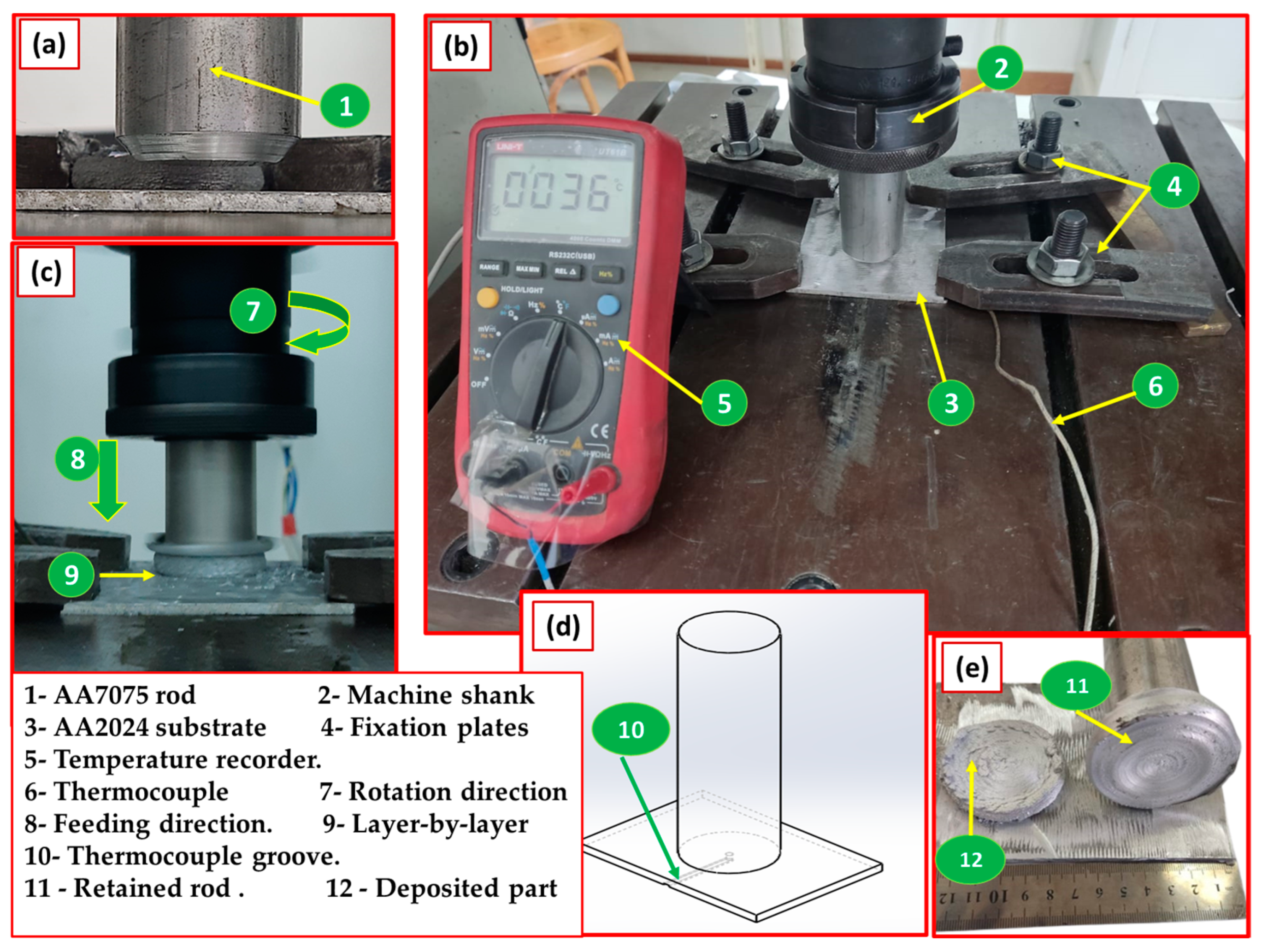
2.1. Initial Materials and Additive Manufacturing Friction Stir Deposition Process

AA7075-T6 aluminum rods were used as consumable feeding rods with a 4 cm diameter and 15 cm length, having a usable length of 10 cm, while the AA2024-T4 aluminum sheets were used as substrate plates with dimensions of 4 × 70 × 100 mm. Table 1 lists the chemical composition of the AA2024-T4 and AA7075-T6 alloy materials, which were produced by Foundry-Master Pro, Oxford Instruments, Abingdon, UK. The AFSD process employed an FSW machine (Model: EG-1 FSW/FSP, SSMMR-CSE, Suez, Egypt) [41]. Based on some experimental trials, the bottom surface of the consumable AA7075-T6 rod was chamfered to promote material flow and to facilitate adhesion between the deposited materials and the substrate alloy, AA2024 (Figure 1a). At the beginning of each experiment, the AA2024-T4 substrate was fastened to the machine table, and the prepared AA7075 rod was gripped in the machine’s rotating shank (Figure 1b). After setting the AFSD parameters on the machine, the consumable rod material of AA7075-T6 rotated and moved downward to reach the surface of the clamped AA2024 substrate. The applied AFSD variables were 200, 400, 600, 800, 1000 and 1200 rpm consumable AA7075-T6 rod rotation speeds and feeding rates from 1 to 5 mm/min. The fed rod was heated by frictional action between the rotating rod and the stationary substrate, plastically deformed and then began to deposit as continuous layers from the bottom to top on the AA2024 aluminum alloy substrate to produce deposited parts (DPs). The generated temperature of the substrate at the center of the deposited part (DP) was measured by an MDMT- UT61B multimeter, made in China, via a K-type thermocouple. In addition, the axial downward force for all the applied AFSD parameters was recorded for each experiment using the machine monitor. Each experiment of the AA7075-T6 deposition trial was repeated three times under the same processing conditions.

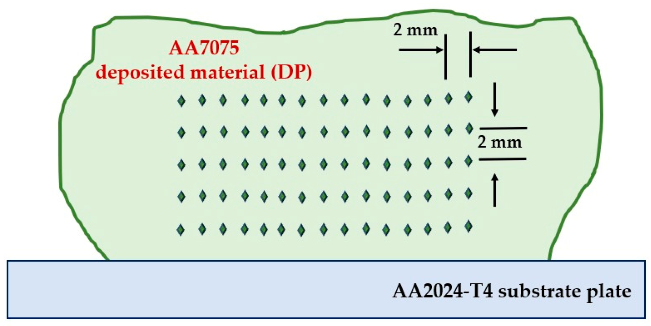
2.2. Characterization of the Additive Manufacturing Deposited Parts

For macro- and microstructure examinations, each DP was cross-sectioned halfway parallel to the deposition direction, ground with silicon carbide abrasive papers up to 2400 grit, and then carefully polished to achieve a surface finish of 0.05 µm alumina, followed by etching using Keller’s solution (92 mL distilled water, 6 mL HNO3, and 2 mL HF). The microstructure investigation was performed for the as-received AA7075-T6 rod, the AA2024-T4 substrate, and the AFSD products using an optical microscope (Type: Zeiss Axiovert 25 CA, Oberkochen, Germany) and a scanning electron microscope (SEM Quanta 3D 200i, FEI, USA). The average grain size and the grain size distribution were determined.
To apply the X-ray diffraction technique, an XRD Panalytical/model X’Pert PRO device diffractometer using Cu Kα1 radiation was used to check the presence phases of the AA7075-T6 rod alloy BM, and the additive friction stir deposited materials, with a processing speed of 400 rpm and feeding rates of 1, 2, 3 and 4 mm/min. The test was fulfilled at 2Ɵ from 10 to 100° and a step size of 0.02°. The hardness of the AA7075-T6 BM and the sectioned DPs was measured using a Vickers hardness testing machine (Type: HWDV-75 TTS Unlimited, Osaka, Japan) at a 500 g load with a holding time of 15 s. To plot the hardness measurements of the deposited materials in contour maps, the selected area of the tested specimen was divided into five horizontal and fifteen vertical lines with a 2 mm step to adjust the indenter locations, as depicted in Figure 2.
To determine the maximum compressive strength, a universal testing machine (WDW-300D, made in China) was used to perform compression tests. The ram speed was kept constant at 1 mm/min. The compression test specimen was prepared according to ASTM E9.

3. Results and Discussion

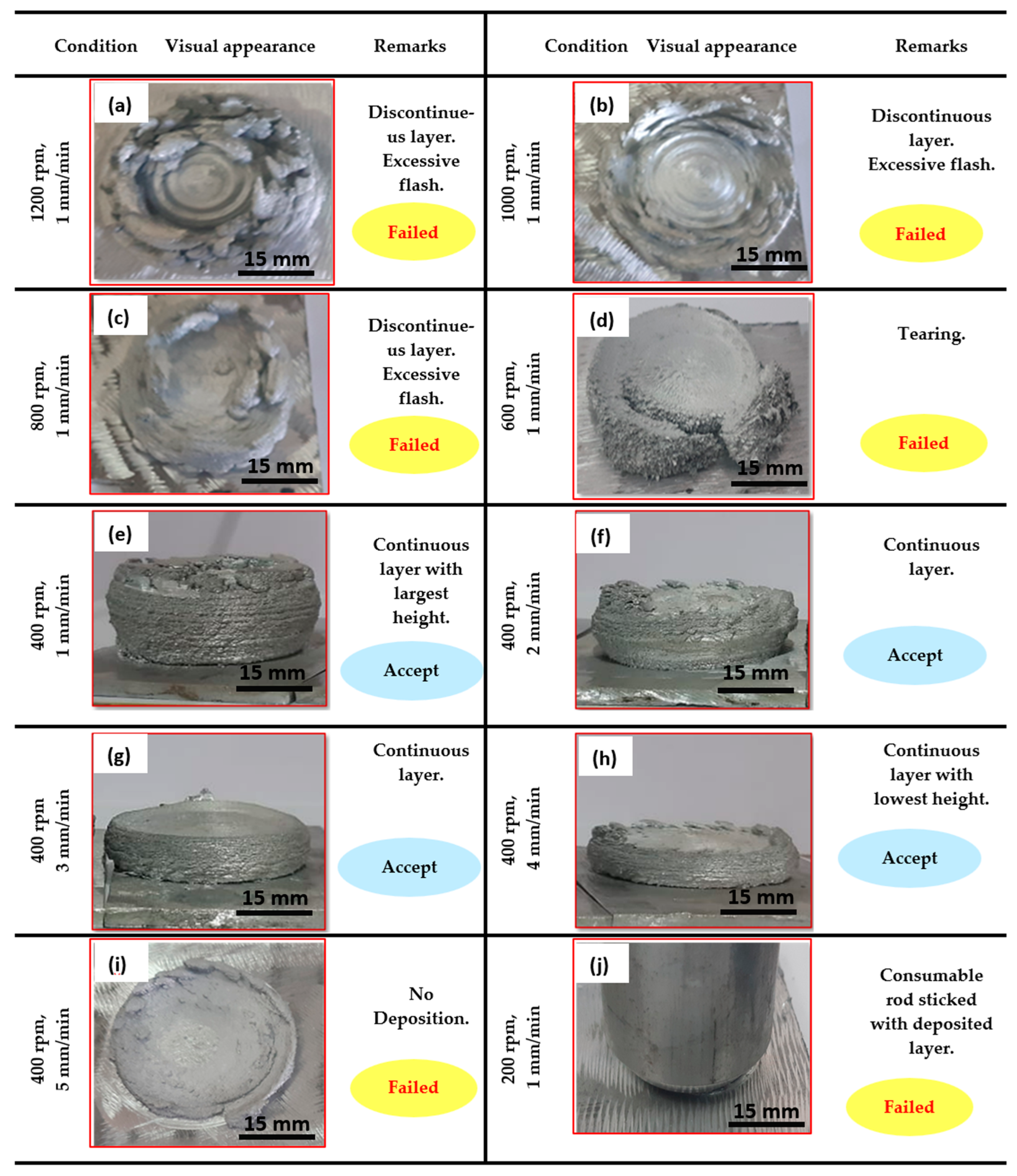
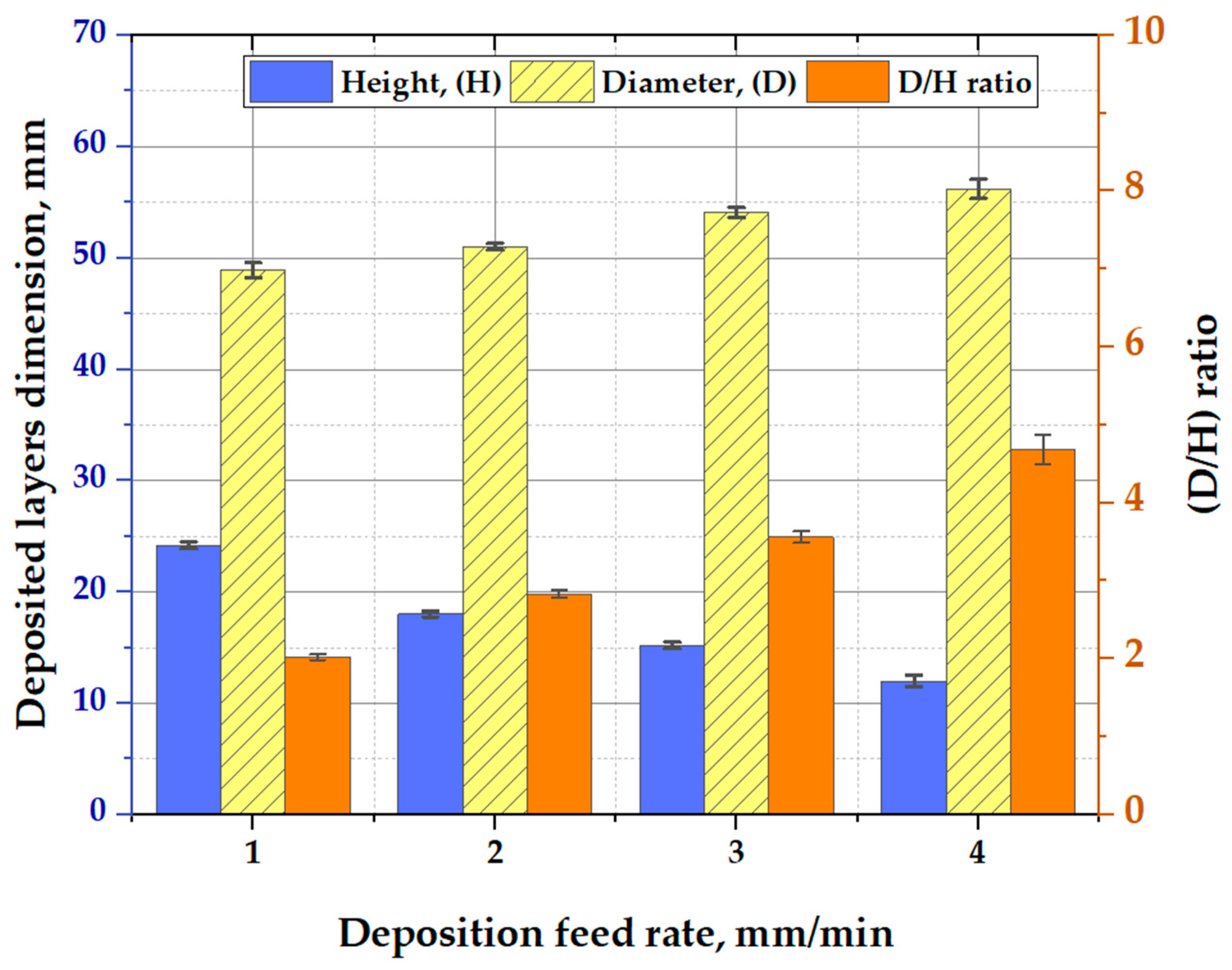
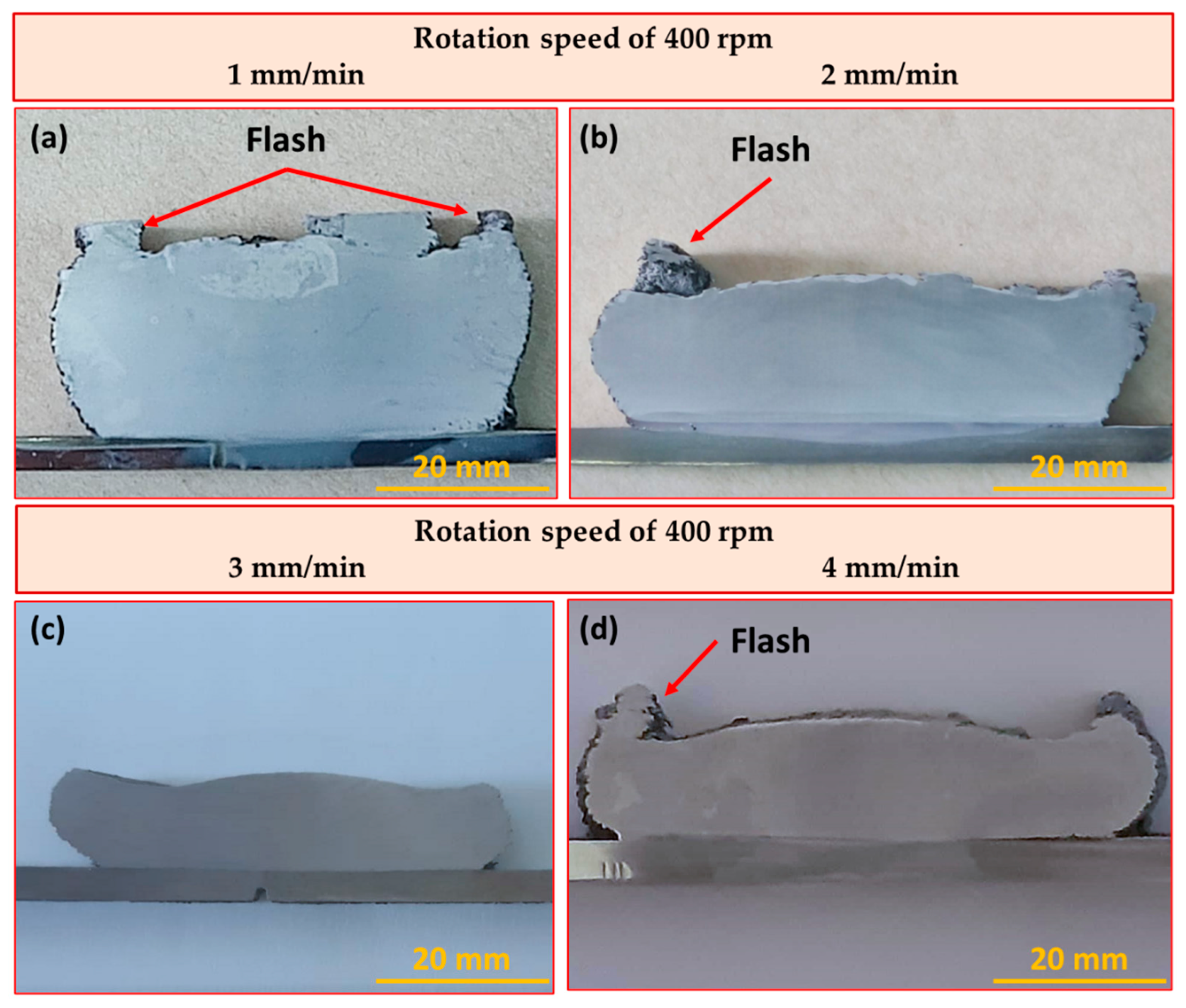
3.1. Visual Inspection of the AFSD Parts

First, experiments were conducted to determine the best AFSD conditions for additively manufacturing DPs that did not have defects like broken deposition layers or excessive flash. The high-strength alloys need special treatment in building continuous multilayers in the solid state, which can be achieved by controlling the factors affecting the deposition process. In previous works [10,13,24,29,37], it was observed that the rotation speed and deposition feed rate of the consumable rod are critical process parameters for AFSD due to their effects on the generated heat input. Wide ranges of rotation speeds and deposition rates were considered in the present work to investigate the applicability of deposition of AA7075-T6 on the AA2024 substrate plate. Figure 3 depicts the DPs produced at rotation speeds ranging from 1200 to 200 rpm using different deposition feed rates ranging from 1 to 5 mm/min. It was observed that the DPs processed at a deposition rate of 1 mm/min and at 1200, 1000, and 800 rpm formed discontinuous layers with an excessive flash, as shown in Figure 3a–c, respectively. In addition, at a 1 mm/min feed rate and 600 rpm rotation speed, the AFSD part suffered from tearing (Figure 3d). In contrast, the DPs processed at different deposition feed rates of 1, 2, 3, and 4 mm/min and a constant rod rotation of 400 rpm showed built-up continuously multilayered parts of AA7075-T6, as shown in Figure 3e–h, respectively. These AFSD parts were fully investigated. On the other hand, the DP processed at 400 rpm and 5 mm/min generated only a deposited layer of AA7075-T6 on the AA2024 substrate plate (Figure 3i). Finally, the last experiment, involving the lowest rotation speed of 200 rpm and the lowest deposition rate of 1 mm/min, showed sticking between the AA7075-T6 consumable rod and the AA2024 substrate at the beginning of the AFSD process, as seen in Figure 3j. Based on a visual inspection of all the additively manufacturing deposited materials, it can be noted that the deposition rates of 1, 2, 3 and 4 mm/min at a constant CRRS of 400 rpm succeeded in building continuously multilayered parts.
Figure 4 displays the impact of applying a constant 400 rpm rotation speed, and 1, 2, 3, and 4 mm/min deposition feed rates on the diameter and height of the DPs. It can be observed that the height of the AA7075-T6 DPs decreased with increasing deposition feed rate, while the diameter of the DPs increased. The plasticity of AA7075-T6 through the AFSD is governed by the developed heat generation due to stirring action throughout the process. This heat input is directly related to the consumable rod’s deposition rate and rotation speed, as well as adjusting the machine’s axial downward force.

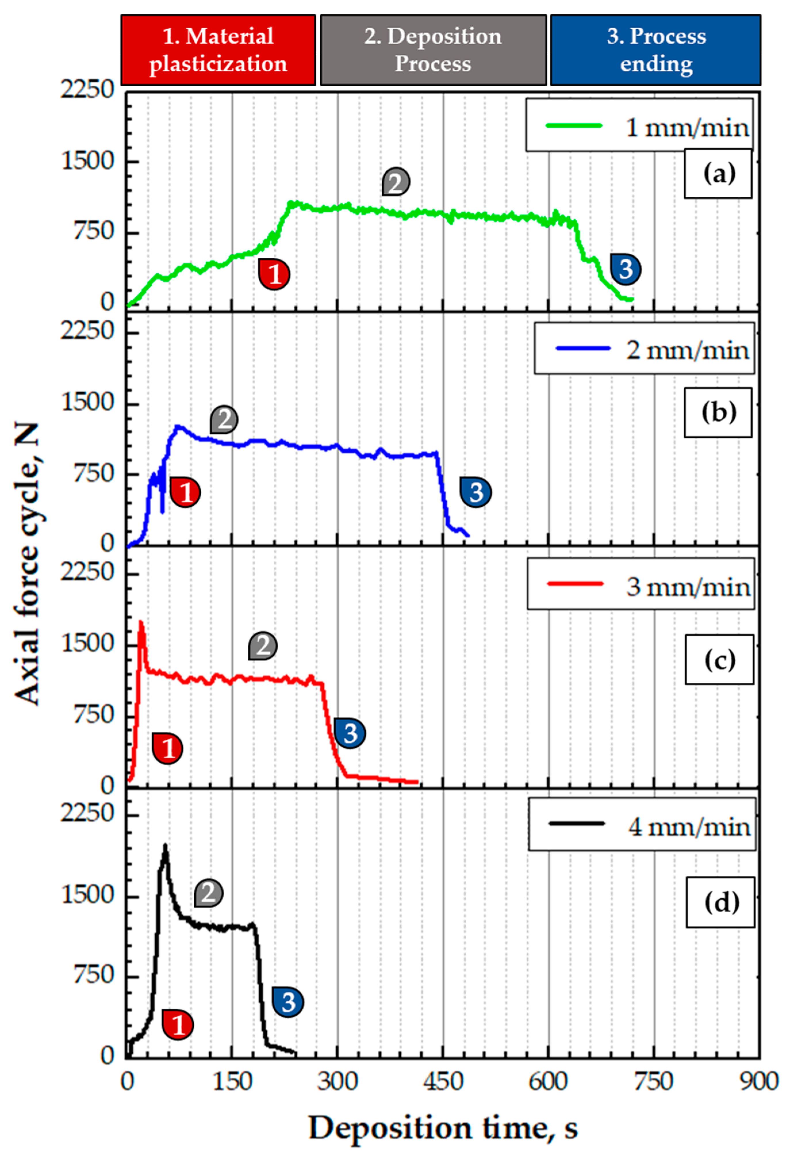
3.2. Additive Friction Stir Deposition Axial Force

During the AFSD process, the machine’s axial downward force was recorded for all the processed materials. Only the successfully produced DPs under the conditions of feed rates from 1 to 4 mm/min and 400 rpm constant rotation speed were plotted against the deposition time. In general, depending on the axial force values, the AFSD procedure has three distinct stages: material plasticization, the deposition process, and process ending. In the beginning, in the first stage, the AA7075-T6 material starts rubbing the AA2024-T4 substrate at the interface with little increase in the axial load. With increasing mechanical friction during the feeding process, the frictional heat generated rises and leads to the plasticization of the tip of the consumable rod material.
Subsequently, in stage 2, the deposition process shows nearly stable axial forces of 976, 1020, 1144, and 1225 N at deposition feed rates of 1, 2, 3, and 4 mm/min, respectively. Thus, it can be noted that the frictional heat generated is adequate to deform and deposit continuously multilayered parts layer-by-layer with a final diameter-to-height (D/H) ratio of 2, 2.8, 3.6, and 4.7, as shown in Figure 4. In the final stage, deposition end, the axial load suddenly decreases after the deposition process ends because the rotating rod moves upwards, as observed in stage 3. From Figure 4, it can be concluded that the time needed to deposit the layers of the DP produced at 1 mm/min (Figure 5a) is longer than the time consumed in building the layers at a 4 mm/min deposition feed rate (Figure 5d).
It is worth noting that the axial force increases with increase in the AA7075-T6 rod feed rates from 1 to 4 mm/min. This trend may be attributed to the fact that a high deposition rate faces more resistance in the deposit layers during the continuous feeding of the rotating consumable rod against the substrate, which causes more axial force to be required to achieve the deposition process than at a low deposition feed rate.

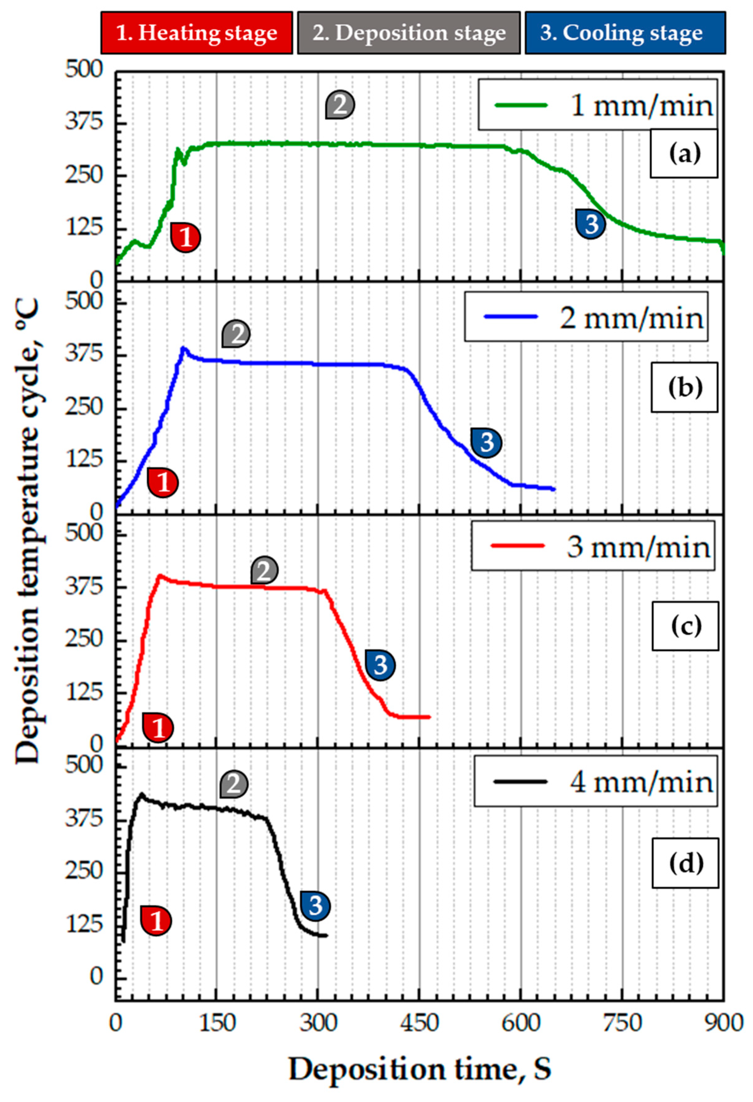
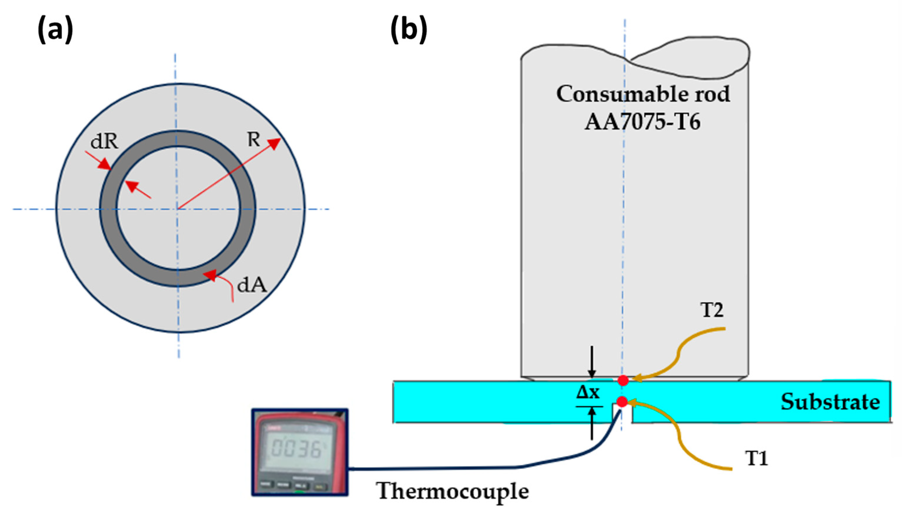
3.3. Thermal Cycle during the AFSD Process

Depending on the friction stir processing parameters [33,42,43,44], the rotating consumable rod during the deposition process and under the machine downward force suffers from both normal and torsional friction forces at its tip during the friction stirring with the fixed substrate on the machine table in the deposition region. To derive an equation for recognizing the amount of heat generated during this process, an annulus with a width dR, an area dA, and an inner radius R at the friction interface between the used rod and the substrate was selected as a representative element for estimation, as illustrated in Figure 6a. This annulus is then subject to a torque of dT. The annulus is the primary heat source in the introductory stage of the deposition process. The generated heat input (Q in watt) to build DPs by the AFSD process is generally described as follows:
dQ = ω × dT
dT = R × dF
dT = R × τFriction × dA
From Equations (1)–(3)
dQ = ω × R × τFriction × dA
T is the applied torque (in N.m), ω is the angular rotation speed (in rad/s).
τFriction = τcontact = μ × P = μ × F/A
dA = R × dR × dθ
τ friction (in Pa) is the friction shear stress at the interface, (F in N) is the axial downward force, (A in m2) is the projected areas, and (P in Pa) is the contact pressure.
Substitute in Equation (4) using Equations (5) and (6)
dQ =   ω   ×   R   × τ contact × R   ×   dR   ×   d θ
dQ =   ω   ×   R   × μ   × P   × R   ×   dR   ×   d θ
dQ =   ω   ×   R 2 × μ   × P × dR   ×   d θ
Q = 0 2 π 0 R ω   ×   R 2 ×   P   × dR   × d θ
Q = 2 3 × π   ×   ω   ×   μ   ×   R 3 × F A
ω = 2 π   N 60
A =   π   R 2
where N is the CRRS (in rpm), R is the consumable rod radius (in m), μ is the friction coefficient between the two rubbing materials (equals 1.35) [45] and F is the deposition axial force. By substitution in Equation (11) using Equations (12) and (13), then:
Q = π 45 × μ   × R   ×   N   ×   F
For an AA7075-T6 rod rotating speed of 400 rpm and different deposition rates (1–4 mm/min), using the measured downward forces at each deposition condition, Table 2 was plotted. It also presents the measured temperature of the AA2024-T4 substrate (T1) via a thermocouple at the position shown in Figure 6b and the generated heat input based on Equation (14).
The temperature of the deposited layer (T2) is calculated depending on the Fourier law of heat conduction by Equation (16)
Q = KA T 1 T 2 Δ x
By substitution in Equation (15) using Equation (14):
T 2 = Δ x   ×   μ   ×   N   ×   F 45   K   ×   R +   T 1
In this equation, K is the material’s conductivity and T1 and T2 are the change in the temperatures across a short distance ( Δ x ).
The AFSD thermal cycles of the DPs were plotted against the deposition time at the recorded downward force for all the applied deposition rates (1–4 mm/min) and a constant 400 rpm rotation speed, as given in Figure 7. Starting from the earliest contact between the bottom surface of the rotating rod and the upper surface of the substrate, along with the continuously increasing deposition rate, heat is generated due to the exerted downward force, and the temperature within the materials increases. The generated temperature is found to be adequate to cause the initial softening of the rubbed materials. It is found to reach its peak value at the onset of the first layer deposition of the AA7075 on the substrate (i.e., rod material plasticization stage as shown in Figure 7), where the plasticization temperatures were 339, 375, 386 and 407 °C at deposition rates of 1, 2, 3 and 4, respectively. With deposition continuation, a temperature plateau is established at the peak temperature that is sufficient to deposit more layers of the rod material, creating the third stage. At the end of the AFSD process, the temperature of the DP is gradually decreased to room temperature during the air-cooling stage.
The plasticizing temperature increases with increase in the deposition rate based on FSW principles [46,47]. At a higher deposition rate, the compressive force of the rotating rod on the substrate and the generation of more frictional heat increase, so that the deposition temperature increases. The highest deposition temperature of 407 ± 4 °C was generated at a deposition feed rate of 4 m/min; meanwhile, the lower deposition feed rate of 1 mm/min generated the lowest temperature of 339 ± 5 °C. It was observed that, at the constant rotation speed (400 rpm), the axial force, heat input, and bulk and substrate temperatures increased with increasing deposition feed rates. Moreover, the rise in temperature of the substrate was less than that of the DP because of the larger heat sink.

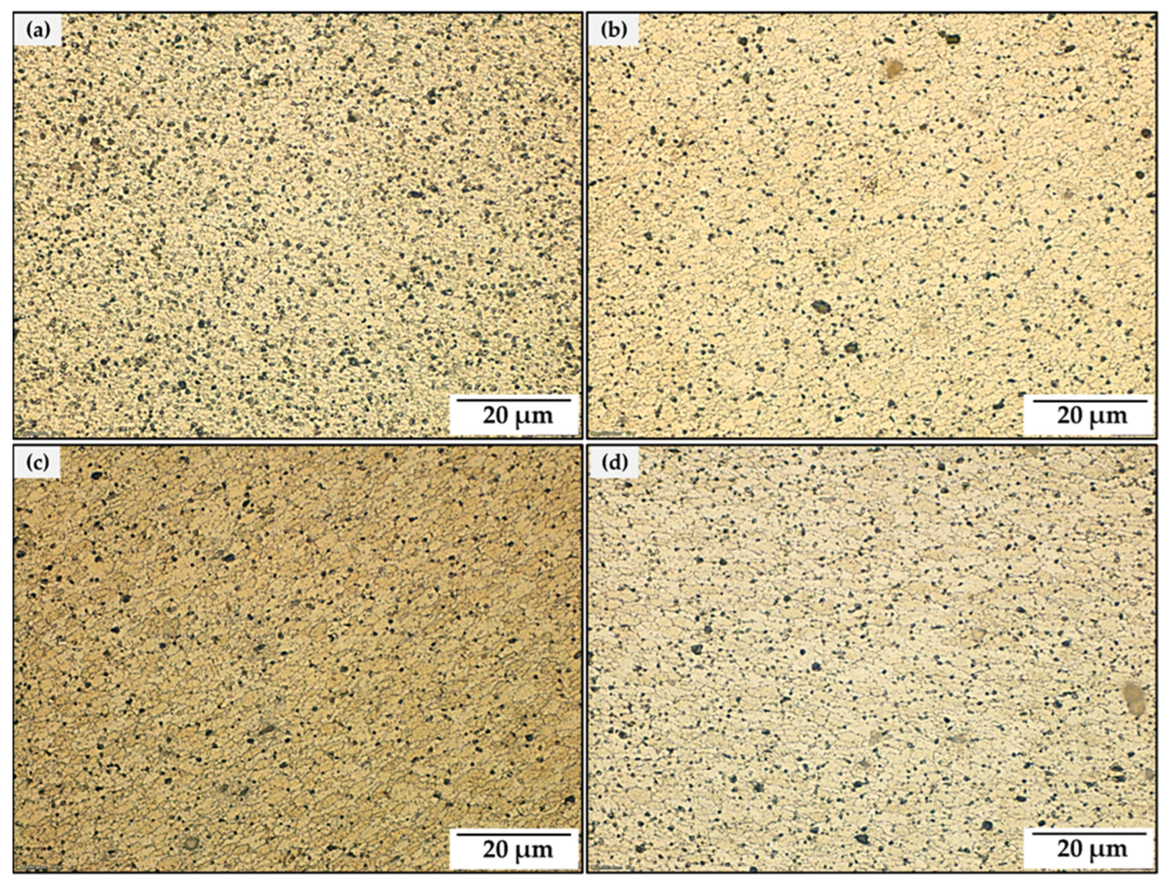
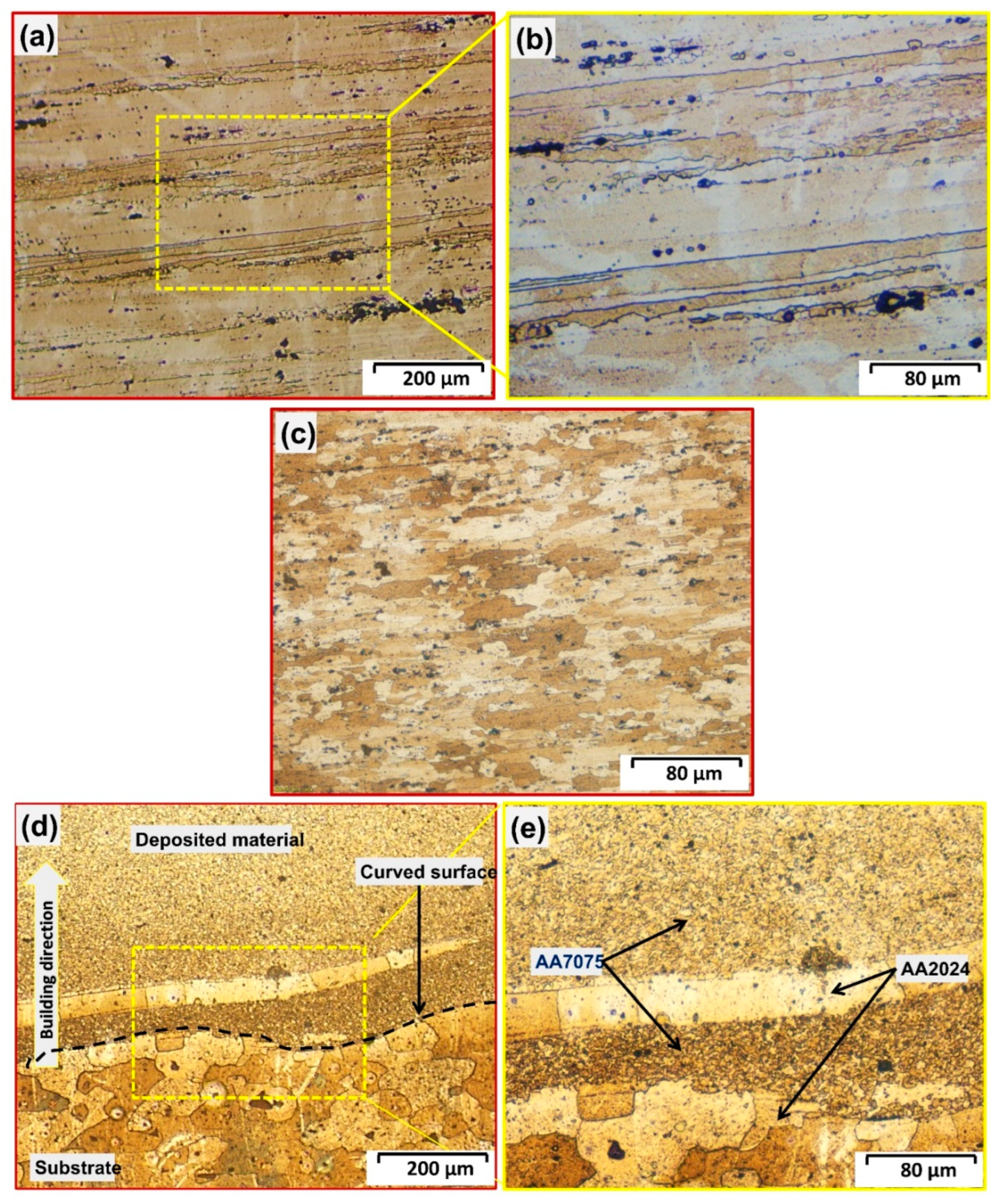
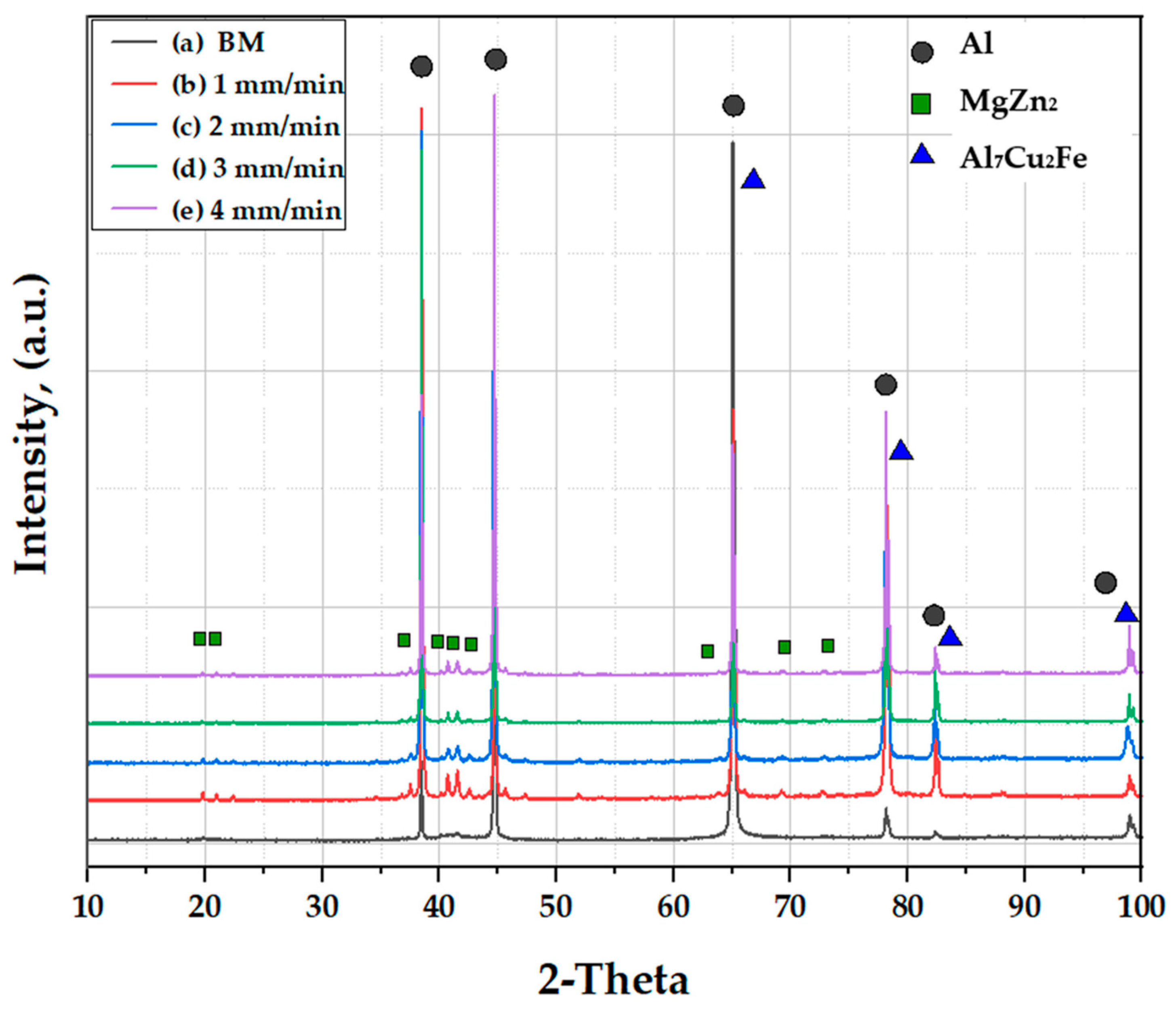
3.4. Macrostructure and Microstructure Investigation

Macrostructure examination of the mid-section revealed sound, defect-free, continuously deposited multilayer build-ups without any obvious separation between the layers along the building direction and no noticeable cracks or voids through the interface between these layers and the substrate in all the produced DPs at the deposition conditions of 400 rpm and feed rates from 1 to 4 mm/min (Figure 8), indicating suitable proposed heat input to achieve defect-free deposited multilayers jointed well with the substrate plate. Optical micrographs of the as-received AA7075 consumable rod, the AA2024 substrate plate and the AA7075/AA2024 interface are shown in Figure 9. Both the grain structures were large and elongated in the deformed direction for the rod material (Figure 9a,b) and the substrate sheet (Figure 9c). The interfacial region between the AA7075 deposited material and the AA2024 substrate is shown in Figure 9d,e. The deposited AA7075/AA2024 substrate interface shows a curved profile, which can be related to the mutual plastic deformation of both the substrate surface and the deposited material, which might involve mixing of the two material alloys and structure linkage. It was reported [1] that this curved interface indicates severe plastic deformation between the substrate surface and the deposited layers. Furthermore, the corresponding structural interlocking is predicted to result in intense material flow, good mixing, and significantly stronger interfacial adhesion.
In the AFSD process, the interfacial adhesion between the deposited material and the substrate is crucial for the overall integrity and performance of the joint [48]. Structural interlocking refers to the mechanical interlocking of the material’s micrometer scale across the interface, which enhances the adhesion strength [49]. During the AFSD process, the rotating tool stirs the material at the interface, resulting in intense plastic deformation and mixing of the material from the substrate and the deposited material. This mixing promotes the adhesion of the deposited layers to the substrate at the atomic scale. The structural interlocking helps in minimizing interfacial defects, such as voids, porosity, and inclusions. The intense plastic deformation and mixing during AFSD promote the redistribution and elimination of these defects, leading to improved interfacial quality and adhesion. Furthermore, the formation of strong metallurgical bonds at the interface due to the mixing of atoms and the refinement of the microstructure facilitate atomic diffusion and solid-state bonding, resulting in a larger contact area and better continuity between the deposited material and the substrate with enhanced interfacial adhesion and improved load-carrying capacity [50].
The AFSD is a thermo-mechanical process, like both FSW [18,51,52,53,54] and FSP [17,55,56,57], in terms of plastic deformation in the deposition zone associated with the heat generation. The temperature in the deposition zone may reach a value ranging from 60 to 80% of the melting point of the consumable rod BM. Thus, the continuously deposited multilayers suffer from a relatively high temperature and severe plastic deformation due to the stirring action under the continuous feed rate and the applied machine axial force. Thereby, the two possible parameters of continuous dynamic recrystallization [58] are established. The obtained microstructure shows significant grain refining compared to the AA7075 rod BM, as given in Figure 10. The DP grain size is noticeably influenced by the AFSD feed rate at a constant rod rotation speed. Figure 11 displays histograms of the average grain size distribution formed at various feeding rates of 1, 2, 3 and 4 mm/min and 400 rpm constant rotation speed. The grain size slightly increases with increasing deposition feed rates as a result of increase in the processing temperature. It attains the average values of 1.75 ± 0.35, 2.25 ± 0.30, 3.25 ± 0.25 and 3.75 ± 0.45 µm at 1, 2, 3 and 4 mm/min feeding rates, respectively, compared to the average grain size value of 52 ± 13 µm for the AA7075 rod BM material in the deposition direction (Figure 9a,b). Figure 9c represents the microstructure of the AA2024 substrate material. Its grains are elongated in the rolling direction and have an average grain size of 33 ± 6.2 µm. Another microstructure feature was noted: that the microstructures of AA7075-T6 BM (Figure 9a,b) and the deposited layers (Figure 9d,e) contain black dots, elongated aggregates, and irregular aggregates. These features were found in the deposited layers as dispersed fragments. Previous studies [59,60,61] indicated that the AA7075 (Al-Zn-Mg-Cu) aluminum alloy contained different types of intermetallic materials in both the T-6 and the friction stir welded or processed conditions. Thus, it can be inferred that the deposition feed rate and the rotation speed are crucial processing parameters that exert a noticeable effect on the presence and distribution of intermetallics in the microstructure of the DPs.
XRD was used as a tool to examine the presence phases for both the AA7075-T6 rod and the additive friction stir deposited materials at 400 rpm and feed rates of 1, 2, 3 and 4 mm/min, as represented in Figure 12. It can be seen that all the XRD patterns revealed typical peaks for the aluminum phase at 2-Ɵ of 38.3, 44.5, 65.0, 78.2, 82.3 and 98.7° as the majority phase. The presence of only small peaks indicates the detection of MgZn2 as a minor phase. This intermetallic appears at 2-Ɵ of 19.7, 20.9, 40.7, 42.5, 51.8, 69.2, and 72.7°. In addition, the possibility of detection of an Al7Cu2Fe phase is not confirmed with the XRD technique used as it appears overlapped with the aluminum peaks, as shown in Figure 12. This phenomenon was observed by Aliyah and Anawati [61] who reported the same phenomenon. Therefore, an advanced SEM-EDS analysis system was used to confirm the possible intermetallics in the AA7075-T6 rod BM and the built material at 400 rpm and a 3 mm/min feed rate, as shown in Figure 13. It can be remarked that the EDS investigation showed three different intermetallics in the aluminum matrix: MgZn2 (Spot 1) AlCuMg, (Spot 2) and Al7Cu2Fe (Spot 3), as shown in Figure 13a,b. The EDS-spots 1, 2 and 3 are represented in Figure 13c–e, respectively. These intermetallics differ in their morphology and phase composition. The intermetallic morphologies in the aluminum matrix alloy are governed by numerous parameters, like chemical composition, type of alloying elements, processing technique and heat treatment program [62,63]. The noted morphologies of the detected intermetallics are elongated intermetallic, almost-spherical and irregular for MgZn2, AlCuMg and Al7Cu2Fe, respectively, as seen in Figure 13. These results are consistent with those mentioned by Ahmed et al. [41] and El-Sayed Seleman et al. [64] for joining AA7075 and AA2024 via FSW. It can also be remarked that the size of these precipitates is profoundly affected by the AFSD process, as they become finer with high dispersion in the deposited continuous multilayers (Figure 13b) compared to the AA7075-T6 rod material (Figure 13a).

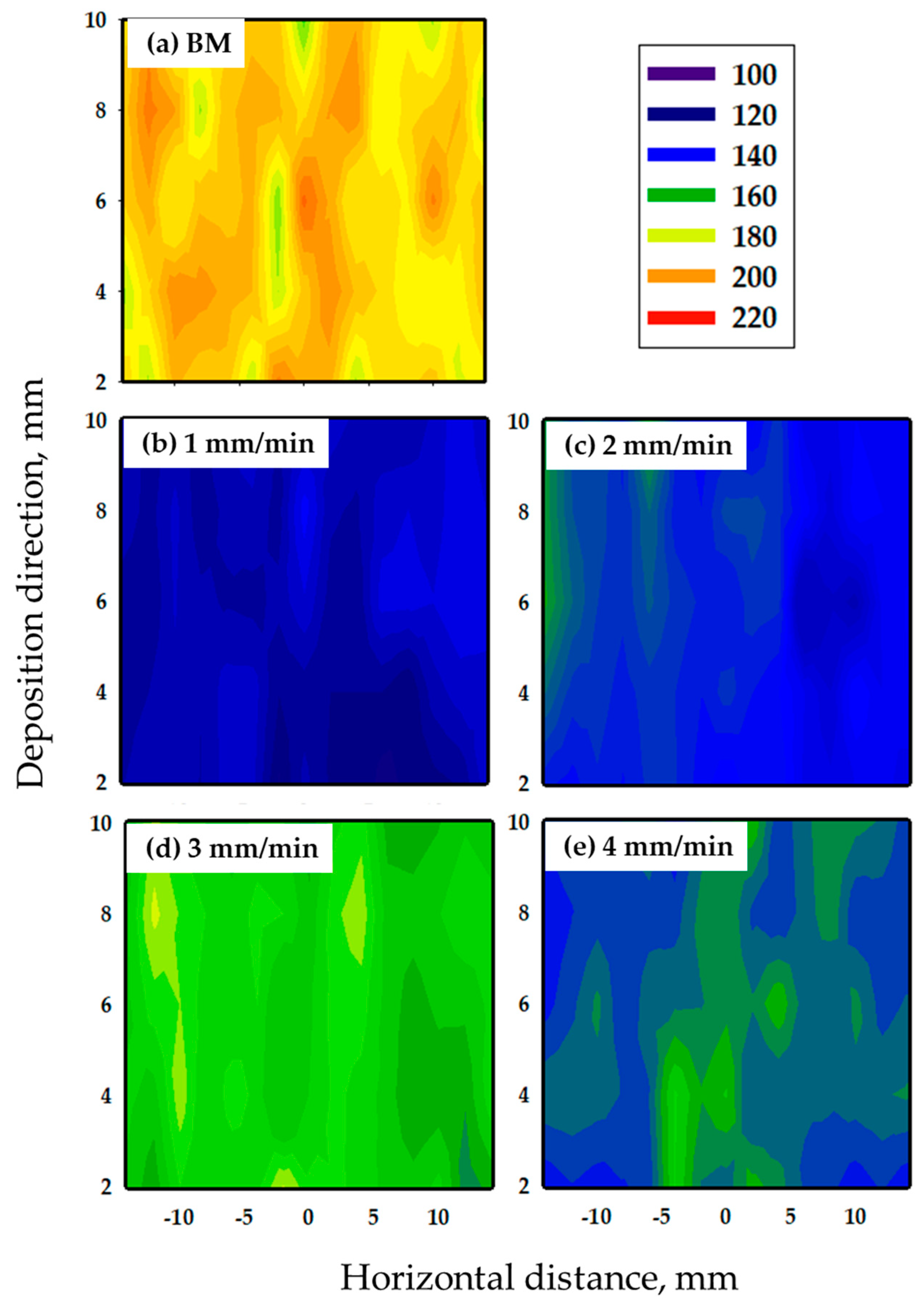
3.5. Mechanical Properties

When compared to the AA7075-T6 rod BM, the variation in hardness along the continuously deposited multilayered portions may provide a better prediction of the mechanisms involved in the deposited layers that result in loss or increase in strength. The hardness values are controlled by the grain size structure and the presence of intermetallics [65,66]. Figure 14 illustrates the hardness variation maps of the AA7075 BM and DP processed at a constant rotation speed of 400 rpm and feeding rats at 1, 2, 3, and 4 mm/min. The AFSD procedure resulted in a more homogeneous hardness distribution across the layers of the deposited materials (Figure 14b–e) than the AA7075-T6 rod material (Figure 14a). In addition, within the DPs, the average hardness increased with increase in the deposition rate from 1 to 3 mm/min. This was followed by a slight decrease at a deposition feed rate of 4 mm/min. These values were 126 ± 5, 142 ± 6, 165 ± 5, and 149 ± 5, with the DPs additively friction stir deposited at a constant rod rotation speed of 400 mm/min and 1, 2, 3, and 4 mm/min, respectively. These values were lower than those given with AA7075-T6 BM. Similar results have been reported in different works when the T6 material was subjected to thermomechanical processes [62,64,67,68,69]. The DP processed at 3 mm/min attained 90% of the AA7075 BM. The hardness of this alloy is controlled by two mechanisms. The first mechanism involves an increase in hardness-related grain size reductions. The morphology, size, and dispersion of the stable intermetallics reflect the second mechanism. These two mechanisms result in increased hardness. However, the hardness of all the produced DPs is lower than the AA7075-T6 BM. This may be due to the fact that the AA7075-T6 is a full precipitation hardened alloy; thus, when exposed to high temperatures during deposition, these precipitates either dissolve or coarsen, thus the hardness is reduced. But the contribution of saturated solid solution (SSS) intermetallic fragmentation and dispersion and grain refining cannot compensate for the loss of hardness due to precipitate dissolution and coarsening [41,70,71].
Figure 15 illustrates the engineering stress–strain curve and the ultimate compressive strength for the AA7075 DPs parts at the studied deposition conditions. It appears that the compressive strength of the DPs increases with increase in the feed rate from 1 to 3 mm/min and then decreases at a 4 mm/min deposition feed rate. In comparison to alloy AA7075-T6 BM, they had noticeably greater compressive strengths and demonstrated the ability to withstand up to 30% strain without fracture. The aluminum alloy’s compressive properties depend on the tested materials’ microstructure. After the AFSD process, the ultimate compressive strength of the DPs was higher than the AA7075-T6 BM at the deposition rate of 3 mm/min, where the maximum compressive strength was 1320 MPa and for the as-received material was 910 MPa. This improvement in compressive strength of the deposited specimen is due to the grain refining and highly dispersed fragmented intermetallics of the DPs [68]. Finally, for the AA7075-T6 DPs, it can be said that the compressive strength is highly affected by grain refining, while the hardness is highly affected by the precipitates.

4. Conclusions

The current study explores the possibility of applying the AFSD technique to build continuous multilayered AA7075-T6 parts on the AA2024 substrate, as well as to optimize the process parameters in terms of rotation speeds (200–1200 rpm) and deposition feed rates (1–5 mm/min). The macrostructures, microstructures, present phases, and mechanical properties were investigated. Based on analysis of the results, the following conclusions can be drawn:
  • The suggested AFSD process successfully fabricated sound continuous multilayered AA7075-T6 DPs without any physical defects (porosity or cavities) using a 400 rpm rotation speed and 1, 2, 3, and 4 mm/min deposition feed rates.
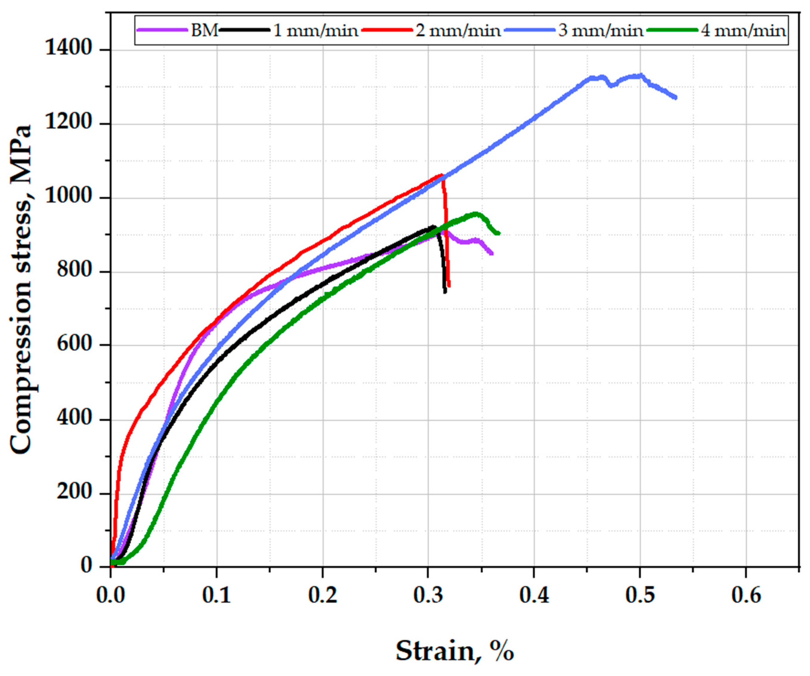
  • The microstructure investigation showed that the AFSD at the applied deposition parameters produced equiaxed fine grain structures compared to the AA7075-T6 rod BM, and the optimum parameters for manufacturing deposited high-performance materials were found to be a CRRS of 400 rpm and a deposition feeding rate of 3 mm/min.
  • The chosen AFSD technique with the applied processing variables gives a more uniform hardness distribution through the cross-sections of the AA7075-T6 deposited materials compared to the AA7075-T6 rod BM.
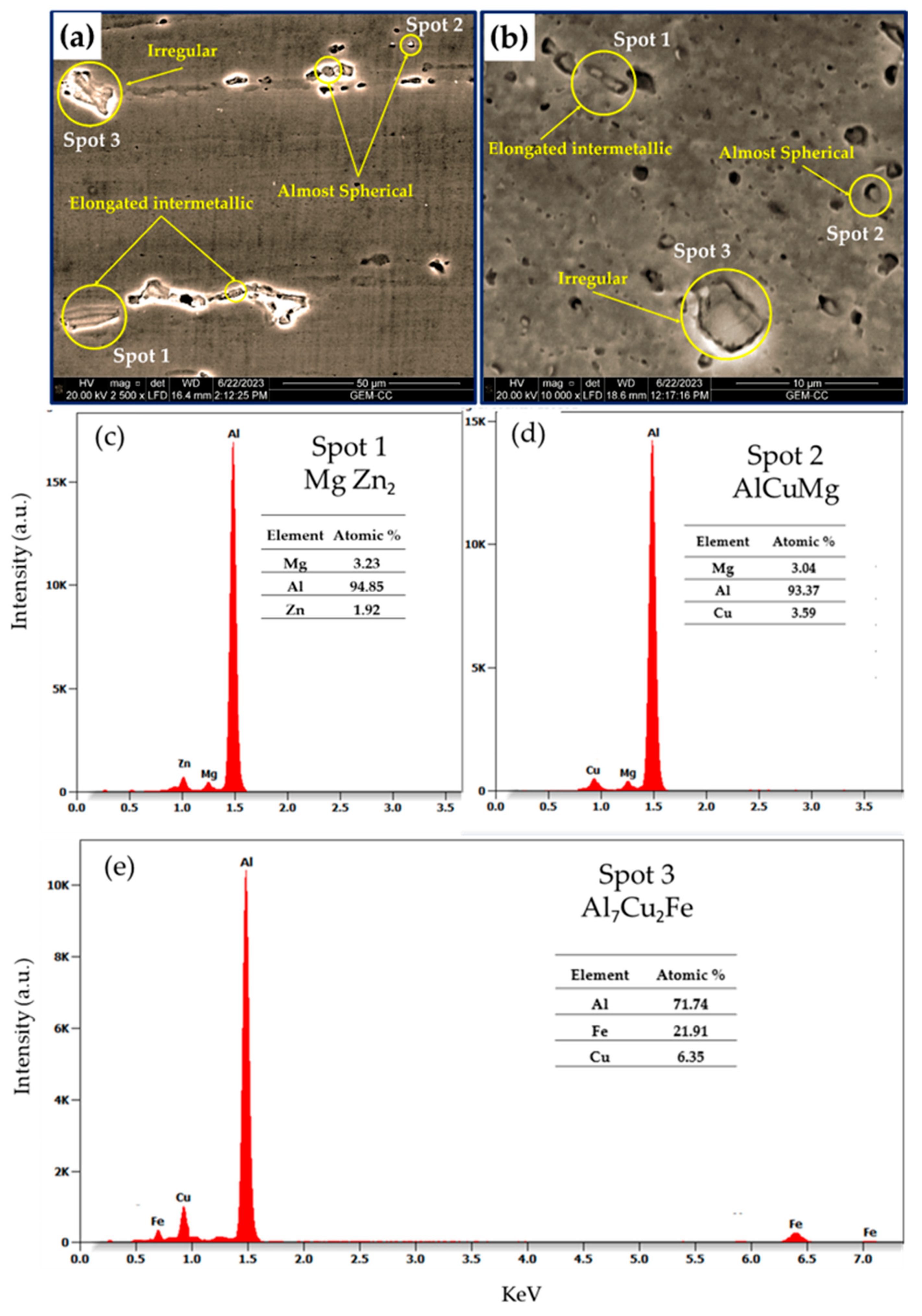
  • The deposition feed rate affects the size and dispersion of intermetallics (MgZn2, AlCuMg and Al7Cu2Fe) at a CRRS of 400 rpm, and the obtained results demonstrate that these precipitates have a direct impact on the strengthening of the deposited layers.

Author Contributions

Conceptualization, M.M.E.-S.S., A.B., M.M.Z.A., I.A. and Y.G.Y.E.; methodology, M.M.E.-S.S., Y.G.Y.E., M.M.Z.A. and A.B.; software, A.B., Y.G.Y.E., A.A.-S. and S.A.E.; validation, A.B., M.M.E.-S.S., M.M.Z.A., R.R. and Y.G.Y.E.; formal analysis, M.M.E.-S.S., M.M.Z.A. and R.R. investigation, I.A., A.B. and Y.G.Y.E.; resources, M.M.E.-S.S., A.B. and M.M.Z.A.; data curation, M.M.E.-S.S. and A.B.; writing—original draft preparation, Y.G.Y.E. and R.R. writing—review and editing, A.B., M.M.E.-S.S., M.M.Z.A. and I.A. visualization, I.A.; supervision, M.M.E.-S.S.; M.M.Z.A. and A.B. project administration A.B. funding acquisition, A.B. All authors have read and agreed to the published version of the manuscript.

Funding

This research was funded by the Deanship of Scientific Research at Umm Al-Qura University for supporting this work by Grant Code: (23UQU4331139DSR003).

Institutional Review Board Statement

Not applicable.

Informed Consent Statement

Not applicable.

Data Availability Statement

Data will be available upon request through the corresponding author.

Acknowledgments

The authors would like to thank the Deanship of Scientific Research at Umm Al-Qura University for supporting this work by Grant Code: (23UQU4331139DSR003).

Conflicts of Interest

The authors declare no conflict of interest.

References

  1. Joey Griffiths, R.; Petersen, D.T.; Garcia, D.; Yu, H.Z. Additive Friction Stir-Enabled Solid-State Additive Manufacturing for the Repair of 7075 Aluminum Alloy. Appl. Sci. 2019, 9, 3486. [Google Scholar] [CrossRef]
  2. Abd El-Hameed, A.M.; Abdel-Aziz, Y.A. Aluminium Alloys in Space Applications: A Short Report. J. Adv. Res. Appl. Sci. Eng. Technol. 2021, 22, 1–7. [Google Scholar] [CrossRef]
  3. Zhang, C.; Huang, G.; Cao, Y.; Zhu, Y.; Liu, Q. On the Microstructure and Mechanical Properties of Similar and Dissimilar AA7075 and AA2024 Friction Stir Welding Joints: Effect of Rotational Speed. J. Manuf. Process. 2019, 37, 470–487. [Google Scholar] [CrossRef]
  4. Bahemmat, P.; Haghpanahi, M.; Givi, M.K.B.; Seighalani, K.R. Study on Dissimilar Friction Stir Butt Welding of AA7075-O and AA2024-T4 Considering the Manufacturing Limitation. Int. J. Adv. Manuf. Technol. 2012, 59, 939–953. [Google Scholar] [CrossRef]
  5. Kumar Srivastava, A.; Kumar, N.; Rai Dixit, A. Friction Stir Additive Manufacturing—An Innovative Tool to Enhance Mechanical and Microstructural Properties. Mater. Sci. Eng. B Solid State Mater. Adv. Technol. 2021, 263, 114832. [Google Scholar] [CrossRef]
  6. Khodabakhshi, F.; Gerlich, A.P. Potentials and Strategies of Solid-State Additive Friction-Stir Manufacturing Technology: A Critical Review. J. Manuf. Process. 2018, 36, 77–92. [Google Scholar] [CrossRef]
  7. Palanivel, S.; Nelaturu, P.; Glass, B.; Mishra, R.S. Friction Stir Additive Manufacturing for High Structural Performance through Microstructural Control in an Mg Based WE43 Alloy. Mater. Des. 2015, 65, 934–952. [Google Scholar] [CrossRef]
  8. Galvis, J.C.; Oliveira, P.H.F.; De Paula Martins, J.; De Carvalho, A.L.M. Assessment of Process Parameters by Friction Surfacing on the Double Layer Deposition. Mater. Res. 2018, 21. [Google Scholar] [CrossRef]
  9. Dilip, J.J.S.; Janaki Ram, G.D. Microstructures and Properties of Friction Freeform Fabricated Borated Stainless Steel. J. Mater. Eng. Perform. 2013, 22, 3034–3042. [Google Scholar] [CrossRef]
  10. Subramaniyan, M.; Karuppan, S.; Eswaran, P.; Appusamy, A.; Shankar, A.N. State of Art on Fusion Deposition Modeling Machines Process Parameter Optimization on Composite Materials. Mater. Today Proc. 2021, 45, 820–827. [Google Scholar] [CrossRef]
  11. Kah, P.; Rajan, R.; Martikainen, J.; Suoranta, R. Investigation of Weld Defects in Friction-Stir Welding and Fusion Welding of Aluminium Alloys. Int. J. Mech. Mater. Eng. 2015, 10, 26. [Google Scholar] [CrossRef]
  12. Mertens, A.I.; Delahaye, J.; Lecomte-Beckers, J. Fusion-Based Additive Manufacturing for Processing Aluminum Alloys: State-of-the-Art and Challenges. Adv. Eng. Mater. 2017, 19, 1700003. [Google Scholar] [CrossRef]
  13. Srivastava, M.; Rathee, S.; Maheshwari, S.; Noor Siddiquee, A.; Kundra, T.K. A Review on Recent Progress in Solid State Friction Based Metal Additive Manufacturing: Friction Stir Additive Techniques. Crit. Rev. Solid State Mater. Sci. 2019, 44, 345–377. [Google Scholar] [CrossRef]
  14. Padhy, G.K.; Wu, C.S.; Gao, S. Friction Stir Based Welding and Processing Technologies—Processes, Parameters, Microstructures and Applications: A Review. J. Mater. Sci. Technol. 2018, 34, 1–38. [Google Scholar] [CrossRef]
  15. Alfattani, R.; Yunus, M.; Mohamed, A.F.; Alamro, T.; Hassan, M.K. Assessment of the Corrosion Behavior of Friction-Stir-Welded Dissimilar Aluminum Alloys. Materials 2022, 15, 260. [Google Scholar] [CrossRef]
  16. Yunus, M.; Alamro, T. Evaluation of Wear and Corrosion Properties of FSWed Aluminum Alloy Plates of AA2020-T4 with Heat Treatment under Different Aging Periods. Rev. Adv. Mater. Sci. 2022, 61, 687–697. [Google Scholar] [CrossRef]
  17. Mishra, R.S.; Ma, Z.Y. Friction Stir Welding and Processing. Mater. Sci. Eng. R Rep. 2005, 50, 1–78. [Google Scholar] [CrossRef]
  18. Nirgude, S.K.; Choudhari, C.M.; Kalpande, S.D. A Review on Pre/Post Treatments Used in Friction Stir Welding. In Proceedings of the International Conference on Advances in Thermal Systems, Materials and Design Engineering (ATSMDE2017), Mumbai, India, 21–22 December 2017. [Google Scholar]
  19. Yu, H.Z.; Jones, M.E.; Brady, G.W.; Griffiths, R.J.; Garcia, D.; Rauch, H.A.; Cox, C.D.; Hardwick, N. Non-Beam-Based Metal Additive Manufacturing Enabled by Additive Friction Stir Deposition. Scr. Mater. 2018, 153, 122–130. [Google Scholar] [CrossRef]
  20. Heidarzadeh, A.; Khodaverdizadeh, H.; Mahmoudi, A.; Nazari, E. Tensile Behavior of Friction Stir Welded AA 6061-T4 Aluminum Alloy Joints. Mater. Des. 2012, 37, 166–173. [Google Scholar] [CrossRef]
  21. Phillips, B.J.; Mason, C.J.T.; Beck, S.C.; Avery, D.Z.; Doherty, K.J.; Allison, P.G.; Jordon, J.B. Effect of Parallel Deposition Path and Interface Material Flow on Resulting Microstructure and Tensile Behavior of Al-Mg-Si Alloy Fabricated by Additive Friction Stir Deposition. J. Mater. Process. Technol. 2021, 295, 117169. [Google Scholar] [CrossRef]
  22. Jinoop, A.N.; Paul, C.P.; Bindra, K.S. Laser-Assisted Directed Energy Deposition of Nickel Super Alloys: A Review. Proc. Inst. Mech. Eng. Part L J. Mater. Des. Appl. 2019, 233, 2376–2400. [Google Scholar] [CrossRef]
  23. Gandra, J.; Krohn, H.; Miranda, R.M.; Vilaça, P.; Quintino, L.; Dos Santos, J.F. Friction Surfacing—A Review. J. Mater. Process. Technol. 2014, 214, 1062–1093. [Google Scholar] [CrossRef]
  24. Phillips, B.J.; Avery, D.Z.; Liu, T.; Rodriguez, O.L.; Mason, C.J.T.; Jordon, J.B.; Brewer, L.N.; Allison, P.G. Microstructure-Deformation Relationship of Additive Friction Stir-Deposition Al–Mg–Si. Materialia 2019, 7, 100387. [Google Scholar] [CrossRef]
  25. Palanivel, S.; Sidhar, H.; Mishra, R.S. Friction Stir Additive Manufacturing: Route to High Structural Performance. JOM 2015, 67, 616–621. [Google Scholar] [CrossRef]
  26. Griffiths, R.J.; Perry, M.E.J.; Sietins, J.M.; Zhu, Y.; Hardwick, N.; Cox, C.D.; Rauch, H.A.; Yu, H.Z. A Perspective on Solid-State Additive Manufacturing of Aluminum Matrix Composites Using MELD. J. Mater. Eng. Perform. 2019, 28, 648–656. [Google Scholar] [CrossRef]
  27. Garcia, D.; Hartley, W.D.; Rauch, H.A.; Griffiths, R.J.; Wang, R.; Kong, Z.J.; Zhu, Y.; Yu, H.Z. In Situ Investigation into Temperature Evolution and Heat Generation during Additive Friction Stir Deposition: A Comparative Study of Cu and Al-Mg-Si. Addit. Manuf. 2020, 34, 101386. [Google Scholar] [CrossRef]
  28. Ahmed, M.M.Z.; El-Sayed Seleman, M.M.; Elfishawy, E.; Alzahrani, B.; Touileb, K.; Habba, M.I.A. The Effect of Temper Condition and Feeding Speed on the Additive Manufacturing of AA2011 Parts Using Friction Stir Deposition. Materials 2021, 14, 6396. [Google Scholar] [CrossRef]
  29. Alzahrani, B.; Seleman, M.M.E.S.; Ahmed, M.M.Z.; Elfishawy, E.; Ahmed, A.M.Z.; Touileb, K.; Jouini, N.; Habba, M.I.A. The Applicability of Die Cast A356 Alloy to Additive Friction Stir Deposition at Various Feeding Speeds. Materials 2021, 14, 6018. [Google Scholar] [CrossRef]
  30. Perry, M.E.J.; Griffiths, R.J.; Garcia, D.; Sietins, J.M.; Zhu, Y.; Yu, H.Z. Morphological and Microstructural Investigation of the Non-Planar Interface Formed in Solid-State Metal Additive Manufacturing by Additive Friction Stir Deposition. Addit. Manuf. 2020, 35, 101293. [Google Scholar] [CrossRef]
  31. Dilip, J.J.S.; Janaki Ram, G.D. Microstructure Evolution in Aluminum Alloy AA 2014 during Multi-Layer Friction Deposition. Mater. Charact. 2013, 86, 146–151. [Google Scholar] [CrossRef]
  32. Griffiths, R.J.; Garcia, D.; Song, J.; Vasudevan, V.K.; Steiner, M.A.; Cai, W.; Yu, H.Z. Solid-State Additive Manufacturing of Aluminum and Copper Using Additive Friction Stir Deposition: Process-Microstructure Linkages. Materialia 2021, 15, 100967. [Google Scholar] [CrossRef]
  33. Liu, X.; Yao, J.; Wang, X.; Zou, Z.; Qu, S. Finite Difference Modeling on the Temperature Field of Consumable-Rod in Friction Surfacing. J. Mater. Process. Technol. 2009, 209, 1392–1399. [Google Scholar] [CrossRef]
  34. Gao, H.; Li, H. Friction Additive Manufacturing Technology: A State-of-the-Art Survey. Adv. Mech. Eng. 2021, 13, 16878140211034431. [Google Scholar] [CrossRef]
  35. Vitanov, V.I.; Javaid, N.; Stephenson, D.J. Application of Response Surface Methodology for the Optimisation of Micro Friction Surfacing Process. Surf. Coat. Technol. 2010, 204, 3501–3508. [Google Scholar] [CrossRef]
  36. Vilaca, P.; Gandra, J.; Vidal, C. Linear Friction Based Processing Technologies for Aluminum Alloys: Surfacing, Stir Welding and Stir Channeling. In Aluminium Alloys—New Trends in Fabrication and Applications; InTech: London, UK, 2012. [Google Scholar]
  37. Elfishawy, E.; Ahmed, M.M.Z.; El-Sayed Seleman, M.M. Additive Manufacturing of Aluminum Using Friction Stir Deposition. In Minerals, Metals and Materials Series; Springer: Cham, Switzerland, 2020; pp. 227–238. [Google Scholar]
  38. Karthik, G.M.; Ram, G.D.J.; Kottada, R.S. Friction Deposition of Titanium Particle Reinforced Aluminum Matrix Composites. Mater. Sci. Eng. A 2016, 653, 71–83. [Google Scholar] [CrossRef]
  39. Mathers, G. The Welding of Aluminium and Its Alloys; CRC Press: Boca Raton, FL, USA, 2002; ISBN 1855735679. [Google Scholar]
  40. Öksüz, K.E.; Baǧirov, H.; Şimşir, M.; Karpuzoǧlu, C.; Özbölük, A.; Demirhan, Y.Z.; Bilgin, H.U. Investigation of Mechanical Properties and Microstructure of AA2024 and AA7075. Appl. Mech. Mater. 2013, 390, 547–551. [Google Scholar] [CrossRef]
  41. Ahmed, M.M.Z.; El-Sayed Seleman, M.M.; Zidan, Z.A.; Ramadan, R.M.; Ataya, S.; Alsaleh, N.A. Microstructure and Mechanical Properties of Dissimilar Friction Stir Welded AA2024-T4/AA7075-T6 T-Butt Joints. Metals 2021, 11, 128. [Google Scholar] [CrossRef]
  42. Ahmed, M.M.Z.; Abdelazem, K.A.; El-Sayed Seleman, M.M.; Alzahrani, B.; Touileb, K.; Jouini, N.; El-Batanony, I.G.; Abd El-Aziz, H.M. Friction Stir Welding of 2205 Duplex Stainless Steel: Feasibility of Butt Joint Groove Filling in Comparison to Gas Tungsten Arc Welding. Materials 2021, 1, 4597. [Google Scholar] [CrossRef]
  43. Karpagarajan, S.; Balamurugan, C.; Vigneshwaran, S.; Abdel Aziz, E.S.I. Effect of Volume Fraction on Microstructure and Wear Behavior of Dual-Phase Brass/W Surface Composites Fabricated via Friction Stir Processing. Proc. Inst. Mech. Eng. Part L J. Mater. Des. Appl. 2023, 237, 1562–1574. [Google Scholar] [CrossRef]
  44. Singh, V.P.; Patel, S.K.; Ranjan, A.; Kuriachen, B. Recent Research Progress in Solid State Friction-Stir Welding of Aluminium–Magnesium Alloys: A Critical Review. J. Mater. Res. Technol. 2020, 9, 6217–6256. [Google Scholar] [CrossRef]
  45. Moran, J. Variations in Dry Sliding Friction Coefficients with Velocity. In Proceedings of the International Conference on Mechanics, Materials, Mechanical Engineering and Chemical Engineering (MMMCE 2015), Barcelona, Spain, 7–9 April 2015; ISBN 9781618042958. [Google Scholar]
  46. Ni, Y.; Mao, Y.; Qin, D.; Xiao, X.; Fu, L. Thermal Cycles and Deformation Characters during High-Speed Micro Friction Stir Welding Process of AA7075-T6 Sheets. Metals 2019, 9, 1236. [Google Scholar] [CrossRef]
  47. Srinivasa Rao, T.; Selvaraj, M.; Koteswara Rao, S.R.; Ramakrishna, T. Thermal Cycles and Their Effects during Friction Stir Welding of AA7075 Thicker Plates with and without In-Process Cooling. Materwiss Werksttech. 2021, 52, 308–319. [Google Scholar] [CrossRef]
  48. Douglas Hartley, W. Processing Mechanics of Additive Friction Stir Deposition. Ph.D. Thesis, Virginia Tech, Blacksburg, VA, USA, 2023. [Google Scholar]
  49. Correia, A.N.; Santos, P.A.M.; Braga, D.F.O.; Baptista, R.; Infante, V. Effects of Friction Stir Welding Process Control and Tool Penetration on Mechanical Strength and Morphology of Dissimilar Aluminum-to-Polymer Joints. J. Manuf. Mater. Process. 2023, 7, 106. [Google Scholar] [CrossRef]
  50. Shirzadi, A. Solid-State Diffusion Bonding; Elsevier: Amsterdam, The Netherlands, 2008. [Google Scholar]
  51. Pankade, S.B.; Ambad, P.M.; Wahane, R.; Gogte, C.L. Effect of the Post-Weld Heat Treatments on Mechanical and Corrosion Properties of Friction Stir-Welded AA 7075-T6 Aluminium Alloy. In Strengthening and Joining by Plastic Deformation: Select Papers from AIMTDR 2016; Springer: Singapore, 2019; pp. 79–94. [Google Scholar]
  52. Boonma, J.; Khammuangsa, S.; Uttarasak, K.; Dutchaneephet, J.; Boonruang, C.; Sirikulrat, N. Post-Weld Heat Treatment Effects on Hardness and Impact Strength of Aluminum Alloy 6061 Friction Stir Butt Weld. Mater. Trans. 2015, 56, 1072–1076. [Google Scholar] [CrossRef]
  53. Zhang, J.; Feng, X.S.; Gao, J.S.; Huang, H.; Ma, Z.Q.; Guo, L.J. Effects of Welding Parameters and Post-Heat Treatment on Mechanical Properties of Friction Stir Welded AA2195-T8 Al-Li Alloy. J. Mater. Sci. Technol. 2018, 34, 219–227. [Google Scholar] [CrossRef]
  54. Qiao, Q.; Su, Y.; Cao, H.; Zhang, D.; Ouyang, Q. Effect of Post-Weld Heat Treatment on Double-Sided Friction Stir Welded Joint of 120 Mm Ultra-Thick SiCp/Al Composite Plates. Mater. Charact. 2020, 169, 110668. [Google Scholar] [CrossRef]
  55. Patel, S.K.; Singh, V.P.; Roy, B.S.; Kuriachen, B. Recent Research Progresses in Al-7075 Based in-Situ Surface Composite Fabrication through Friction Stir Processing: A Review. Mater. Sci. Eng. B Solid State Mater. Adv. Technol. 2020, 262, 114708. [Google Scholar] [CrossRef]
  56. Gholami, S.; Emadoddin, E.; Tajally, M.; Borhani, E. Friction Stir Processing of 7075 Al Alloy and Subsequent Aging Treatment. Trans. Nonferrous Met. Soc. China (Engl. Ed.) 2015, 25, 2847–2855. [Google Scholar] [CrossRef]
  57. Johannes, L.B.; Mishra, R.S. Multiple Passes of Friction Stir Processing for the Creation of Superplastic 7075 Aluminum. Mater. Sci. Eng. A 2007, 464, 255–260. [Google Scholar] [CrossRef]
  58. Fouad, D.M.; El-Garaihy, W.H.; Ahmed, M.M.Z.; Albaijan, I.; El-Sayed Seleman, M.M.; Salem, H.G. Grain Structure Evolution and Mechanical Properties of Multi-Channel Spiral Twist Extruded AA5083. Metals 2021, 11, 1276. [Google Scholar] [CrossRef]
  59. Zheng, K.; Li, Y.; Yang, S.; Fu, K.; Zheng, J.; He, Z.; Yuan, S. Investigation and Modeling of the Preheating Effects on Precipitation and Hot Flow Behavior for Forming High Strength AA7075 at Elevated Temperatures. J. Manuf. Mater. Process. 2020, 4, 76. [Google Scholar] [CrossRef]
  60. Chemin, A.; Marques, D.; Bisanha, L.; Motheo, A.d.J.; Bose Filho, W.W.; Ruchert, C.O.F. Influence of Al7Cu2Fe Intermetallic Particles on the Localized Corrosion of High Strength Aluminum Alloys. Mater. Des. 2014, 53, 118–123. [Google Scholar] [CrossRef]
  61. Aliyah, A.N.; Anawati, A. Effect of Heat Treatment on Microstructure and Mechanical Hardness of Aluminum Alloy AA7075. In IOP Conference Series: Materials Science and Engineering; Institute of Physics Publishing: Bristol, UK, 2019; Volume 541. [Google Scholar]
  62. Hao, Z.; Shaokang, D.; Zeming, M.; Jun, W. Study on the Precipitation Behavior of Precipitates of 7075 Aluminum Alloy Friction Stir Welding Joint. In Materials Science Forum; Trans Tech Publications Ltd.: Wollerau, Switzerland, 2020; Volume 1003, pp. 37–46. [Google Scholar]
  63. Isadare, A.D.; Aremo, B.; Adeoye, M.O.; Olawale, O.J.; Shittu, M.D. Effect of Heat Treatment on Some Mechanical Properties of 7075 Aluminium Alloy. Mater. Res. 2013, 16, 190–194. [Google Scholar] [CrossRef]
  64. Seleman, M.M.E.S.; Ahmed, M.M.Z.; Ramadan, R.M.; Zaki, B.A. Effect of FSW Parameters on the Microstructure and Mechanical Properties of T-Joints between Dissimilar Al-Alloys. Int. J. Integr. Eng. 2022, 14, 1–12. [Google Scholar] [CrossRef]
  65. Heidarzadeh, A.; Mironov, S.; Kaibyshev, R.; Çam, G.; Simar, A.; Gerlich, A.; Khodabakhshi, F.; Mostafaei, A.; Field, D.P.; Robson, J.D.; et al. Friction Stir Welding/Processing of Metals and Alloys: A Comprehensive Review on Microstructural Evolution. Prog. Mater. Sci. 2021, 117, 100752. [Google Scholar] [CrossRef]
  66. Heidarzadeh, A.; Javidani, M.; Mofarrehi, M.; Farzaneh, A.; Chen, X.G. Submerged Dissimilar Friction Stir Welding of Aa6061 and AA7075 Aluminum Alloys: Microstructure Characterization and Mechanical Property. Metals 2021, 11, 1592. [Google Scholar] [CrossRef]
  67. Mehri, A.; Abdollah-zadeh, A.; Entesari, S.; Saeid, T.; Wang, J.T. The Effects of Friction Stir Welding on Microstructure and Formability of 7075-T6 Sheet. Results Eng. 2023, 18, 101041. [Google Scholar] [CrossRef]
  68. Kosturek, R.; Torzewski, J.; Wachowski, M.; Śnieżek, L. Effect of Welding Parameters on Mechanical Properties and Microstructure of Friction Stir Welded AA7075-T651 Aluminum Alloy Butt Joints. Materials 2022, 15, 5950. [Google Scholar] [CrossRef]
  69. El-Sayed Seleman, M.M.; Ataya, S.; Ahmed, M.M.Z.; Hassan, A.M.M.; Latief, F.H.; Hajlaoui, K.; El-Nikhaily, A.E.; Habba, M.I.A. The Additive Manufacturing of Aluminum Matrix Nano Al2O3 Composites Produced via Friction Stir Deposition Using Different Initial Material Conditions. Materials 2022, 15, 2926. [Google Scholar] [CrossRef]
  70. Zhou, Y.; Zhou, J.; Xiao, X.; Li, S.; Cui, M.; Zhang, P.; Long, S.; Zhang, J. Microstructural Evolution and Hardness Responses of 7050 Al Alloy during Processing. Materials 2022, 15, 5629. [Google Scholar] [CrossRef]
  71. Ahmed, M.M.Z.; El-Sayed Seleman, M.M.; Fydrych, D.; Çam, G. Friction Stir Welding of Aluminum in the Aerospace Industry: The Current Progress and State-of-the-Art Review. Materials 2023, 16, 2971. [Google Scholar] [CrossRef] [PubMed]
Figure 1. (a) Consumable rod chamfer, (b) setup of the AFSD process of the AA7075 rod on the AA2024 plate, (c) onset of deposition process, (d) schematic drawing of thermocouple layout, and (e) final deposited product.
Applsci 13 10255 g001
Figure 2. Sketch showing indenter locations for hardness measurements of the AA7075 DP.
Applsci 13 10255 g002
Figure 3. Shows photographs of the deposited materials formed by the AFSD technique processed at different rotation speeds (1200–200 rpm) and various feed rates (1–5 mm/min) and the visual inspection remarks.
Applsci 13 10255 g003
Figure 4. AA7075 deposited part dimensions in terms of diameter (D) and height (H) and their D/H ratios processed at 400 rpm and different deposition feed rates.
Applsci 13 10255 g004
Figure 5. Axial force cycle during the AFSD process of the AA7075-T6 deposited at various deposition feed rates of (a) 1, (b) 2, (c) 3 and (d) 4 mm/min and 400 rpm.
Applsci 13 10255 g005
Figure 6. (a) The scheme of an element at the friction interface and (b) the temperature measuring position in the substrate.
Applsci 13 10255 g006
Figure 7. Thermal cycle of the AFSD process against the deposition time for the DPs processed at 400 rpm and different feed rates of (a) 1, (b) 2, (c) 3 and (d) 4 mm/min.
Applsci 13 10255 g007
Figure 8. Macrographs of the AA7075 DPs processed at deposition feed rates of (a) 1, (b) 2, (c) 3 and (d) 4 mm/min and at a fixed CRRS of 400 rpm.
Applsci 13 10255 g008
Figure 9. Optical microstructures: (a) AA7075-T6 rod BM, (b) at higher magnification of (a), (c) the AA2024 plate, (d) the interfacial region between AA7075 deposited layers and the AA2024 substrate of the specimen processed at 400 rpm and 3 mm/min, and (e) at higher magnification of (d).
Applsci 13 10255 g009
Figure 10. OM-imegs of the obtained microstrctures of the AA7075 DPs processed at different deposition feed rates of (a) 1, (b) 2, (c) 3, and (d) 4 mm/min and at 400 rpm.
Applsci 13 10255 g010
Figure 11. Grain size distribution histograms of the AA7075 DPs fabricated at feed rates of (a) 1, (b) 2, (c) 3 and (d) 4 mm/min and 400 rpm.
Applsci 13 10255 g011
Figure 12. XRD analysis for (a) the AA7075-BM, (b) the DPs processed at 1, (c) 2, (d) 3 and (e) 4 mm/min feed rates and 400 rpm.
Applsci 13 10255 g012
Figure 13. SEM-images show microstructures of (a) AA7075-T6 rod BM, (b) DP processed at 400 rpm and 3 mm/min, (c) EDS spot 1 (d) EDS spot 2 and (e) EDS spot 3.
Applsci 13 10255 g013
Figure 14. Hardness map distribution of the (a) AA7075-T6 BM amd the deposited AA7075-T6 materials produced at different deposition rates of (b) 1, (c) 2, (d) 3, and (e) 4 mm/min and a constant CRRS of 400 rpm.
Applsci 13 10255 g014
Figure 15. Compressive stress–strain curves for the AA7075-T6 BM and the DPs processed at different deposition conditions.
Applsci 13 10255 g015
Table 1. Chemical composition of the AA7075-T6 and AA2024-T4 alloys.
AA7075-T6
ElementSiMnCuZnFeMgCrAl
Wt.%0.360.191.145.720.232.620.20Bal.
AA2024-T4
ElementFeSiMgTiZnMnCuAl
Wt.%0.130.321.150.140.120.444.48Bal.
Table 2. The axial force, heat input, and temperature during the FSD of AA7075-T6.
Deposition Rate,
(mm/min)
Rotation Speed,
RPM
Axial Force,
Kg
Heat Input,
Watt
T1:
Substrate Temp, °C
T2: Deposited Layer
Temp, °C
14009767173.60330339
210207497.00352375
311448408.40375386
412259003.75395407
Disclaimer/Publisher’s Note: The statements, opinions and data contained in all publications are solely those of the individual author(s) and contributor(s) and not of MDPI and/or the editor(s). MDPI and/or the editor(s) disclaim responsibility for any injury to people or property resulting from any ideas, methods, instructions or products referred to in the content.

