Abstract
The detection of partial discharge (PD) activities in high-voltage equipment can be conducted according to several mechanisms of signal detection, including electromagnetic wave signal detection, acoustic signal detection, chemical reactions, electrical signal detection, and optical emission detection. Recently, multiple methods of detection and localization of partial discharge activities, which occurred in power transformers and gas-insulated switchgear (GIS), have been proposed to monitor the health condition of high-voltage equipment, especially when the awareness regarding preventive maintenance has been emphasized at the industrial level and among electrical providers. In aligning the needs of the industrial sector and the improvement of PD-detection methods, this manuscript focuses on reviewing the current practice methods for the detection and localization of PD signals in high-voltage equipment, comparing their efficacy, and summarizing the future direction of research work-related methods of PD detection. The comparative reviews are discussed in terms of the mechanism of PD signal detection, indication parameters, calibration techniques, and the advantages and limitations of each method of PD measurement in detail.
1. Introduction
Power transformers are essential equipment in power delivery systems in increasing and decreasing the voltages to reduce the dissipated power [1,2]. Therefore, it is crucial to maintain the good operating condition of this equipment to prevent the occurrence of unpredicted breakdown phenomena and minimize any potential power supply interruptions that could cause substantial financial losses during corrective action [3]. However, the exposure of power transformers to certain conditions, such as thermal aging, mechanical stress, electrical stress, and vulnerable environment, might trigger, and result in, insulation failure. Therefore, preventive maintenance is necessary for monitoring the performance of the power transformer to prevent a major breakdown of the essential equipment. The outcomes from the monitoring aid in identifying further action, including whether the power transformers can work well in the power delivery system or if preventive action needs to be made accordingly. Implementing performance monitoring on the power equipment is crucial to avoid disruption of the electricity supply and ensure the continuous and reliable functioning of power system utilities [4]. Generally, the method of condition monitoring power transformers are listed, such as dissolved gas analysis (DGA) [5,6]; partial discharge measurement [7]; power factor measurement [8]; frequency-response analysis (FRA) [9]; vibration plus acoustic analysis [10]; dielectric spectroscopy [11]; differential protection [12]; transformation ratio [13]; and insulation resistance [14].
The power transformer is a multifaceted entity that is susceptible to encountering diverse anomalies, which can be classified as either endogenous or exogenous faults. As depicted in Figure 1, various types of faults may arise in distinct regions, including on the winding, tank, insulating oil, core, terminal, cooling system, and tap changer, as highlighted in reference [15]. The external faults commonly manifest as a result of external short circuits within the power system, over-flux phenomena, or overloading. Various fault location areas exist for transformers situated within substations (operating at voltages greater than 100 kV), as documented in reference [16]. The pre-eminent realm where faults manifest is within the winding, exhibiting a likelihood of occurrence at 37.69%. Subsequently, the tap changer constitutes the second-most plausible site of fault occurrence (31.16%), succeeded by the third delineated fault location, positioned at the bushing (17.2%). Comparatively diminutive probabilities are attributed to other fault locations, including the lead exit insulation (8.96%), core and tank (3.54%), cooling system (1.12%), and current transformer (0.37%). Instances of anomalies in these latter regions are infrequent during regular operational states.
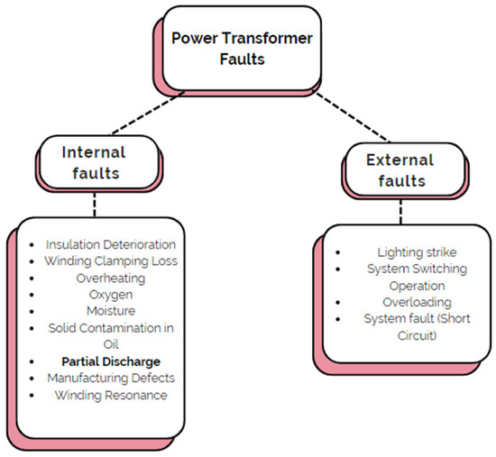
Figure 1.
Power transformer failure classification [15].
Conversely, the causes of internal faults in transformers are diverse and include factors such as axial displacement, buckling deformations, disc space variation, short-circuited turns, core insulation failure, shorted laminations, open leads, loose connections, short circuits, overheating, and other issues described in references [9,17,18,19,20]. Globally, the majority of transformer faults, approximately 70–80%, are attributed to internal faults [21]. The aforementioned deficiencies generally originate as partial discharges within the insulation of the transformer, which occur swiftly and culminate in total failure.
The identification of the condition of a power transformer is of utmost importance in guaranteeing the uninterrupted functioning of electrical utilities. This is because the severity of the different types of defects might increase from time to time [22]. One of the measurements considered in the preventive maintenance of power transformers is the measurement of partial discharge activities. Partial discharge is a pre-breakdown phenomenon that indicates the electrical discharge that partially bridges the dielectric medium between two conduction parts. Under the influence of high-voltage stress, partial discharge (PD) can or cannot occur adjacent to a conductor [23]. As mentioned in the standard, a PD pulse refers to the current or voltage pulse that typically occurs due to a partial discharge activity within the object under test. PD usually begins due to the imperfections of the insulation medium, such as the presence of voids or gas-containing bubbles on the dielectric materials [24]. Commonly, imperfections on the insulation medium are present due to improper manufacturing processes. Chemical by-products and particle bombardment produced by PD activity also degrade the properties of the insulating medium. Protracted PD may eventually lead to insulation breakdown.
Generally, the PD testing method of power transformers can be conducted either online or offline. Offline testing is preferred compared to online testing despite its lack of dependability [2]. In order to obtain reliable outcomes from the measurement of PD activities, the appropriate calibrated PD measurement system needs to be used, and it must be performed according to the standard of commercial PD measurement techniques. Nevertheless, the PD measurement technique conducted offline has limitations, especially in accounting for the authentic electrical and thermal circumstances experienced by the insulation while the transformer is in operation [25]. Therefore, in sustaining the performance of installed power transformers, online detection of the partial discharge phenomenon must be conducted accordingly. Recently, several prevalent techniques have been conducted to monitor the PD characteristics in power transformers.
As stated, PD is considered to be the primary factor responsible for the deterioration of insulation in transformers, which can ultimately result in failure [26,27]. Various techniques for PD detection have been performed in condition monitoring to detect, identify, and diagnose PD [28]. In addition, numerous methodologies have been developed to identify and detect partial discharge (PD), including electrical detection [29,30,31,32,33], electromagnetic detection [26,34,35,36,37,38], optical detection [39,40,41], acoustic detection [42,43,44,45,46], gas presence detection [6,47,48,49], and integrated approaches [42,50,51]. In order to pinpoint the spots and PD activities, these methods have been utilized to determine the PD signals. In online PD monitoring, it has been found that there are challenges to detecting the PD signals and their exact proposition due to the complicated geometrical of power transformers, the shielded structure of power transformers, and interruption of noise (i.e., noise interference). For instance, electrostatic and electromagnetic interference, radio frequency interference, and crosstalk brought on by nearby cables are all examples of external disturbances which may lead to noise interference in PD detection. Additionally, the transformer’s core and windings produce the majority of the internal noise. Therefore, an applicable method to detect PD is needed to prevent any breakdown happening in the power transformer or gas-insulated switchgear. Partial discharge detection methods encompass a range of techniques, in which each offering unique insights into the early identification and localization of PDs within electrical systems. The method that is currently being used to detect PD include the UHF method. The UHF method utilizes UHF sensors or antennas placed near the transformer or GIS to capture and analyze the electromagnetic emissions generated by PD events. This method offers high sensitivity, accurate PD localization, and the ability to detect PDs in their early stages. It is commonly used for both online and offline monitoring [52,53]. Other than that, Transient Earth Voltage (TEV) method also can be used to detect PD. The TEV method detects the radiated electromagnetic waves resulting from PD events in a power transformer or GIS. It involves placing sensors on the transformer’s surface or GIS surface to measure high-frequency transient signals. The TEV method is non-intrusive, highly sensitive to PD events, and suitable for online monitoring systems [54,55]. Apart from that, acoustic detection also is one of the methods that are currently being used to detect PD. Acoustic PD detection relies on the measurement of sound waves produced by PD events. Acoustic sensors or ultrasonic detectors are used to capture and analyze acoustic emissions. This method is effective for detecting PDs in power transformers or gas-filled compartments of GIS and provides information about the discharge location based on time-of-flight analysis [56,57].
2. Method of PD Detection Based on Different Types of Signals Emitted during PD Activities
2.1. Electromagnetic Method
W. R. Rutgers was the first to apply the EM method to a power transformer in 1997 [58]. UHF signals can be detected using conical, spiral, and Vivaldi antennas [26,59]. UHF sensors are the subject of extensive research since they have benefits that include immunity to low-frequency signals, an insignificant impact of signals caused by internal transformer construction, and the absence of corona-free pulse interference [34,60]. Radio interference and switching events might make UHF detection more difficult.
For its measurements, the UHF electromagnetic technique depends on the PD activation of electrical resonance at frequencies up to 1.5 GHz. This technique can also detect and pinpoint a PD source [61,62]. The UHF method offers multiple benefits; for instance, low decibel levels as a sequence of the transformer’s shielding effect and extremely low signal losses. The measurement frequency band of 100 MHz of such a UHF process fits precisely between 300 and 1500 MHz of the entire wavelength range, permitting it to avoid local interference over the entire range. Because the UHF sensor is linked to the transformer, this technology is noise free. The secondary winding is safe and dependable against induced current since there is no electrical interrelation between a power transformer and a UHF sensor. The secondary winding of a power transformer is safe and reliable against induced current.
Figure 2 is a circuit diagram for a power transformer that was used in [63] to analyze the impact of various PD types on UHF calibration. Researched causes of PD include surface discharge on polyethylene, surface discharge on pressboard, internal discharge, and corona discharge. There are six drain valves that facilitate the placement of various UHF probes. The optimal detection frequency range for measuring the UHF signal in terms of PD activities was introduced by the authors in [63]. They also showed how inefficient the UHF probe was because of the difficulty in reducing calibration errors caused by active transformer components. However, a maximum charge estimation approach was presented in [63], where the UHF quantifier parameter and IEC apparent charge are measured in the laboratory to achieve the least feasible ratio.
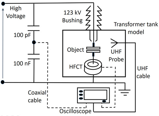
Figure 2.
Schematic depicting the effects of various PD types on UHF calibration in a power transformer reprinted by [63].
Extensive research has been conducted on various types of current transformers, such as Rogowski coils, high-frequency current transformers (HFCTs), and radio frequency current transformers (RFCTs), for their application as PD detection sensors in power transformers [64,65,66]. The electromagnetic (EM) technique has proven effective in localizing multiple PD sources and identifying their unique characteristics through the use of feature extraction and denoising strategies. These strategies are used in PD detection through the EM signal approach to accurately identify and analyze PD signals in power transformers.
2.2. Electrical Method
One of the electrical measurement approaches for detecting PD is the pulse capacitive coupler method. In a pulse capacitive coupler arrangement, the PD-induced current is gathered and measured in the detecting coil, which is coupled in a loop with some impedance to the ground line [67]. Quantitative approaches are highly sensitive and simple to implement. However, because of its high sensitivity, it is prone to false alarms, making it unsuitable for continuous transformer monitoring.
EE detection techniques utilize the existing pulse-produced signal to detect PD. The circuit is connected to the spotted areas, allowing it to detect current pulses that indicate PD activity [68]. The International Electrotechnical Commission (IEC) and the Institute of Electrical and Electronics Engineers (IEEE) both utilize similar techniques [69]. This method may be used to determine the PD charge and evaluate the insulation’s state. The assessment of PD detection systems in power transformers has been advised by the International Council on Large Electric Systems (CIGRE) [70]. Many variations can be derived from the basics of PD test circuits. The electrical detection techniques most often used for power transformer status monitoring are shown in Figure 3a,b, which include the test circuit for measuring self-excited test objects as well as the test circuit for measurement at a tapping of a bushing, respectively [71]. A coupling capacitor (Ck) is connected in parallel with the capacitance of the insulation system being tested (Ca) in the measurement setup shown in Figure 3a. The PD measurement device that is connected to a measuring input impedance (Zm) will compute the apparent charges.
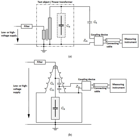
Figure 3.
(a) IEC 60,270 based on test circuit for measuring self-excited test objects; (b) test circuit for measurement at a tapping of a bushing reprinted by [71].
On the other hand, Figure 3b illustrates an arrangement that is suitable for testing objects equipped with capacitance-graded bushings in which the bushing capacitance is used in place of the coupling capacitor, Ck. When the bushing is equipped with a tapping and it is connected to the coupling device, in this case, a relatively large capacitance (Cm) appears across the input impedance (Zm) of the coupling device which potentially impacts the measurement’s sensitivity. The existence of that large capacitance makes this technology impractical for online testing. However, online testing is feasible if the power transformer has available bushing taps, as depicted in Figure 3b.
Currently, there are limitations in identifying PD activities using this online testing. The presence of electromagnetic interference during online testing poses challenges [72,73]. Therefore, offline testing is preferred, although it may not fully represent the conditions of online operation. For regular tests of produced goods or pre-commissioning routine tests, offline testing is still useful. Even with these drawbacks, this method offers useful insights into the comprehension of the insulation performance.
2.3. Chemical Method
Chemical testing procedures, which depend on the analysis of gas and oil specimens extracted from the PD activities, are essential for identifying PD in high-voltage applications. High-performance liquid chromatography (HPLC) and dissolved gas analysis (DGA) are two frequently used methods for measuring chemicals. HPLC is employed to study the by-products of PD, such as glucose in its degenerated forms resulting from insulation breakdown [74,75]. On the other hand, DGA utilizes differential gas chromatography to analyze the entire volume of gas generated by PD activities [74]. These approaches provide valuable insights into the chemical composition of PD-related substances, aiding in the detection and assessment of PD in high-voltage systems.
A variety of online testing methods have been developed to detect partial discharge (PD) in power systems. These approaches include oil-immersed sensors with fiber Bragg gratings [76], photoacoustic spectroscopy [77], and oil-immersed sensors [78]. Other than that, photoacoustic spectroscopy with membrane-based methods [79], and hydrogen detection [76]. Figure 4 [80,81] shows a typical gas chromatography setup. In this configuration, the oil specimen undergoes vaporization near the injection port, and the resultant gases—which include some of the lighter gases including argon, the element helium nitrogen, and hydrogen—are then fed into the column. The column separates the gases based on their retention times before they reach the heat detectors [80]. The data collection system records and plots the identified PD signals, generating chromatograms.
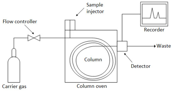
Figure 4.
Gas chromatograph in its usual form [80].
The gas concentration and retention time are then used to determine the identity of the gases. Hydrogen gas detection has become the preferred method due to its high accuracy and has largely replaced other detection methods. If the hydrogen gas level exceeds the safety threshold during overheating and discharges, it indicates a need to diagnose the internal insulations [82]. FBG sensors have been extensively used in various studies to measure the concentration of hydrogen gas within power transformer tanks operating at typical temperatures ranging from 60 °C to 90 °C. The remarkable sensitivity of hydrogen gas detection at 80 °C, combined with its minimal interference from other gases, points towards a promising outlook for this technology [83]. Furthermore, there have been advancements in the development of Pd-capped Mg-Ti thin-film-based hydrogen sensors (improved FBG), which exhibit enhanced sensitivity over a broader temperature range from 10 °C to 80 °C and significantly surpass the sensitivity of traditional FBG sensors [84].
2.4. Acoustic Method
The mechanical explosion that causes AE in the power transformer is caused by the evaporation of oil in the area of the streamer, the electrical arc, and the mechanical vibration [85]. Ultrasonic signals, with a frequency of 40 kHz to hundreds of kHz [86,87], can be used to estimate the location of the AE source, which sends off pressure waves with characteristics exclusive to that source. Nevertheless, the signals of PD can be affected by high-frequency signals and can be removed if using a denoising technique.
The AE approach has become the preferred technique to detect PD in power transformers due to its effectiveness and low cost in eliminating electromagnetic interference. The break down of the components of the recording system which have been commonly used by the power transformer during normal operation to identify AE signals from PD is shown below [88]. Many ultrasonic systems use broadband piezoelectric transducers as their transduction element. These AE signal detectors are attached to the transformer tank at a certain point using a magnetized holder. The AE signals are then transferred into the AE analyzer, where they are amplified, filtered, and recorded.
Multiple PD causes can be identified using the AE technique [86]. The AE method is often used in conjunction with others, such as UHF, optical detection, and electrical detection, to compensate for its limitations in PD-level detection and calibration. Complex acoustic emission behavior, weak detected signals, and a high price tag are all downsides of this approach. Microphones [89], piezoelectric transducers [86], acceleration sensors [86], and fiber optic (FO) sensors [90] are all examples of equipment that can be used to detect AE. Fiber optic sensors have been shown to be the most effective AE detection devices because of their high signal-to-noise ratio (SNR) and their ability to detect over a wide acoustic field. The internal design of the transformer can be optimized and noise reduced using denoising techniques, allowing for the detection of several PD sources. The biggest issue with the AE method is the inability to pinpoint the PD source in the transformer winding due to the quick attenuation of the signal as it travels through the various media [91].
In summary, we can break down the components of the recording system which have been commonly used in power transformer monitoring to identify Acoustic Emission (AE) signals from partial discharge (PD) during normal operation.
- Test Transformer: This is a specific type of transformer used for testing and monitoring purposes. It is designed to mimic the behavior of the power transformer under normal operating conditions;
- Transducer: The transducer is a device that converts the acoustic signals generated by the partial discharge events in the power transformer into electrical signals. It effectively picks up the acoustic emissions and transforms them into measurable electrical signals;
- Preamplifier: The electrical signals from the transducer are typically weak and need to be amplified for further processing. The preamplifier is responsible for boosting the weak signals to a level suitable for subsequent stages in the recording system;
- Track Signal and Filter: After amplification, the AE signals may contain unwanted noise or irrelevant frequencies. The track signal and filter stage are used to filter out unwanted frequencies and ensure that the signals of interest are properly isolated;
- Broadband Amplifier: The filtered AE signals are further amplified using a broadband amplifier. The amplifier boosts the desired AE signals to a level suitable for accurate measurement and analysis;
- Measurement and Card or Analyzer: This is the core component responsible for processing and analyzing the amplified AE signals. It may be a dedicated hardware card or a specialized analyzer device designed to detect and analyze AE signals from partial discharges;
- Computer: The final stage involves recording the processed AE signals on a computer for storage and further analysis. The computer may have specialized software to handle data logging, signal visualization, and in-depth analysis of the recorded AE signals.
The purpose of this recording system is to continuously monitor the power transformer for any signs of PD events, which can be indicative of insulation degradation or other potential failures or issues. By detecting and analyzing AE signals, maintenance personnel can take proactive measures to address developing problems before they escalate into major faults, thereby ensuring the reliability and longevity of the power transformer.
2.5. Optical Method
Power transformer oil can be tested for PD activities using the optical technique. Scientists have used a variety of light detection techniques to conduct PD analysis on transformer oil/paper insulation. Mach–Zehnder interferometry, Fabry–Perot interferometry, and fiber Bragg grating are typical examples of optical sensors used for detecting PD [33]. Using a single-mode fiber and laser, MZI was the first optical fiber-based sensor. At first, a fiber coupler separates the incoming light into two separate fibers. The first detecting fiber optic coil is placed in the oil tank’s PD signal zone, while the second fiber serves as a reference for the light’s raytracing path. The EFPI sensor incorporates a silica diaphragm inside a capsule-shaped silica glass tube to create a single optical fiber. Because of their excellent dielectric property and immunity from electromagnetic interference, FBG sensors are currently employed in power transformers and kept directly in the oil. For a visual representation of the FBG’s operating principle, see Figure 5 [92], where Λ is the grating period, n is the refractive index, and λB is the reflected wavelength called the Bragg wavelength. It works as narrowband reflective optical sensors since they reflect only one wavelength of light by grating and let all the other wavelengths be transmitted through it.
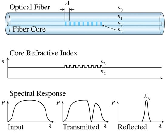
Figure 5.
Fiber Bragg grating principle operation, with refractive index profile and spectral response [92].
Initially, it was determined that fluorescent optical sensors could only detect PD from light emission in air, and not in transformer oil. In 2013, it was discovered that the optical method, using the fluorescent sensor and an unconventional technology, was accurate for PD measurement in power transformers. However, the fluorescent sensor research for PD detection in transformer oil produced dubious results with numerous shortcomings. The attempts to establish a link between photon activity, PD via an optical signal, and PD charge restrictions in oil have been conducted aggressively. Based on [93], the measurement was made possible in the oil-immersed transformer. This, however, proved difficult, especially when dealing with dated transformer oil [94]. Nevertheless, the technique used in [93] works best to measure a wide variety of chemical elements and physical properties, and it has the advantages of having a high-frequency response and being immune to electromagnetic interference [32]. Major limitations include the inability to calibrate PD detection, a lack of data on PD magnitude, and the inability to reliably identify discharges within transparent media. Current research is focused on improving methods for detecting and locating PD in transformer oil. On the other hand, it is also being studied about the X-ray emission as a method of PD detection since it does not require the complicated geometry of a power transformer.
2.6. Combinational Method
The combination of dissolved gas analysis (DGA) and acoustic emission (AE) practices has been employed to identify and localize the partial discharge (PD) anomalies that occur inside power transformers. This integration enables the detection and pinpointing of PD anomalies by using both DGA and AE methods. The detection process involves initially conducting offline dissolved gas analysis (DGA) to assess the gas content, followed by implementing acoustic emission (AE) detection for a duration of 24 h to identify the sources of PD. This approach aims to replicate the daily load cycle and has been documented in reference [95]. An example of the integration of acoustic emission (AE) and dissolved gas analysis (DGA) methods is photo-acoustic spectroscopy (PAS). The operational concept of PAS is illustrated in Figure 6, as described in reference [96]. In this technique, fault gases interact with an infrared source, receiving kinetic energy. The pressure signals are detected by a microphone and converted into electrical signals. By analyzing the amplitude of the sound waves generated and filtering them through optical filters, different gases can be identified.
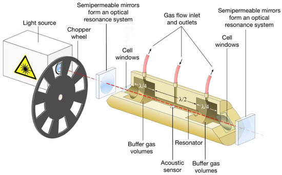
Figure 6.
A DGA system utilizing photo-acoustic spectroscopy [96].
The integration of electromagnetic (EM) and acoustic techniques has also been employed. Ultrasonic and ultra-high-frequency (UHF) sensors, configured in various geometries, have shown remarkable effectiveness in detecting the origin of partial discharge (PD) within a specific range, as reported in reference [97]. A proposed approach involves the use of a hybrid PD detection system that combines acoustic emission sensors plus transient earth wire voltage (TEV) [98]. Novel techniques for detecting acoustic emission (AE) involve the use of AE sensors to identify the presence of partial discharge (PD) based on a reference time obtained from electrical equipment (EE) signals. This approach enables the localization and validation of the detected signal, ensuring it is not attributed to external noise [99].
The technique for identifying PD by combining acoustic emission (AE), electrical equipment (EE), and dissolved gas analysis (DGA) to evaluate the transformer’s entire insulating state, as reported in reference [100]. A noise rejection system for PD detection might be created by combining AE and EE approaches. The information gathered via EE detection could be utilized to pinpoint the PD’s origin. The sensitivity of the AE method can be enhanced by integrating using the EE technique, where the latter serves to initiate events.
A combination of AE and optical techniques involves the use of a Fabry–Perot fiber as an AE sensor for localizing PD. In addition, a fluorescent optical fiber acts as an optical sensor to verify signal of reference originates from a PD source, as documented in reference [101]. Table 1 provides a comparative analysis of the advantages and limitations of various techniques used for detecting PD inside power transformers.

Table 1.
Summary of the advantages and disadvantages of different partial discharge detection methods.
3. Type of Sensor Used to Detect PD Signals
3.1. Electrical–Electromagnetic Sensor
PD is an electrical discharge occurrence characterized by a spark or discharge that occurs when a small section of insulation is partially bridged. It happens when two conductive electrodes with high densities of positive and negative charges become separated. When the applied voltage exceeds a specific critical value called PD inception voltage, transient gas ionization leads to a localized discharge within the insulated system. PD is considered a pre-breakdown phenomenon. PD occurs on micro-/nano-sized voids/cavities/gas-contained bubbles even though the power transformers still can operate. Without PD detection/PD mapping/preventive action, the PD activities keep occurring on the power transformers making the voids/cavities/gas-contained bubbles more significant, and eventually forming a conductive path that completely bridges the two conduction parts; eventually, leading to the major breakdown.
The identification and detection of partial discharge (PD) in power transformers are vital in industrial and power delivery systems to prevent the failure of high-voltage equipment [107,108]. The use of UHF sensors for PD detection in gas-insulated substations (GIS) is depicted in Figure 7a. These sensors have shown to be successful in both on-site PD testing and laboratory PD measurement. The use of a UHF sensor to evaluate the compatibility of power transformers on DN50/DN80 gate valves is also demonstrated in Figure 7b. The sensor provides alternative methods for estimating PD, and the illustrated setup, referred to as a bushing tap, is specifically designed for measuring galvanically connected decoupling. Figure 7c depicts a configuration of an inductive UHF sensor used to take a reading on the power cable termination [109].
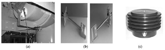
Figure 7.
There are three types of electrical sensors: (a) a UHF sensor attached to a GIS grounding bar; (b) an oil valve sensor for the reactor of a power transformer (left side) for use with a DN 50 gate valve and (right side) for a DN 80 gate valve; (c) an inductive UHF sensor for the termination of a power cable [109].
Figure 8a illustrates three distinct UHF sensors that are suitable for the purpose of PD detection on both power transformers and gas-insulated switchgear. Conventionally, the three types of sensors utilized for PD detection, according to reference [110], are disc-type, monopole-type, and spiral-type sensors. Recent research has revealed that these sensors accumulate a significant amount of energy, demonstrating their excellent sensitivity in detecting emitted signals [110]. Meanwhile, Figure 8b depicts a capacitive coupler used in a high-voltage cable for PD detection. The capacitive sensor is linked through a 40 mm tin tape that encircles the uncovered cable. The insulation measurement on the cable remains unaffected by the capacitive sensor coupler due to its effective connection at UHF, wherein it functions as the power frequency ground, as stated in reference [111].
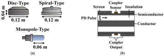
Figure 8.
(a) Disc-type, monopole-type, and spiral-type UHF sensors. (b) Capacitive coupler schematic. Reprinted by [32,110].
3.2. Acoustic Sensor
The acoustic method employs an extremely sensitive sensor made of a specialized piezoelectric film, depicted in Figure 9a, and set up as shown in Figure 9b. This technique is used to measure partial discharges (PD) in high-voltage equipment like power transformers and high-voltage cables. When functioning at low resonant frequencies, the piezoelectric sensor film adopts a disc-shaped crystalline structure, facilitating straightforward calculation of its resonances. As explained in reference [112], this precise arrangement makes it simple to determine resonances.
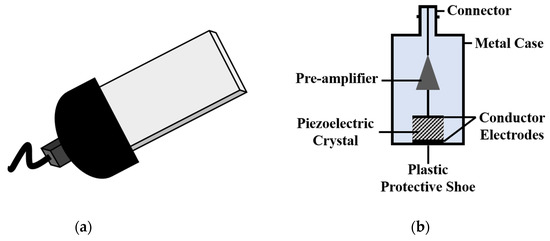
Figure 9.
(a) A connectorized piezoelectric film sensor and (b) conventional piezoelectric [112].
3.3. Optical Sensor
The prevailing technique to detect (PD) occurs in HV transformers and GIS equipment is by optical detection technique utilizing a fiber intrinsic sensor coil. Figure 10a presents a depiction of the sensor coil, which is created by coiling 8 m of fiber around a former, resulting in a coil with a 25-millimeter diameter. This intrinsic sensor is based on Mach–Zehnder fiber interferometers and operates using single-mode optical fiber typically submerged inside oil along the transformer being tested to measure its PD characteristics [113]. Meanwhile, Figure 10b illustrates the multimode optical fiber sensor specifically designed for PD detection in GIS [114].
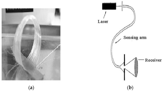
Figure 10.
Intrinsic optical sensors; (a) Mach–Zehnder fiber interferometer-based optical fiber sensor and (b) multimode optical fiber sensor. Reprinted by [113,114].
Furthermore, Figure 11a,b showcase the extrinsic Fabry–Perot interferometer sensor and extrinsic microelectron–mechanical system sensor, respectively, both utilized for measuring PD in oil-cooled high-voltage transformers [115].
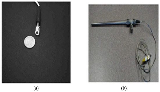
Figure 11.
Extrinsic optical sensors. (a) The Fabry–Perot interferometer sensor and (b) the microelectromechanical system sensor. Reprinted by [115].
4. Partial Discharge Measurement Using Different Types of Sensors on the Power Transformer and GIS
4.1. Mechanism in Electric–Electromagnetic Sensors
When the insulating materials (i.e., solid, liquid, or gas) are subjected to a high electric field and the electric field exceeds the PD inception electric field, PD activities will occur rapidly [116]. The phenomenon of partial discharge can be explained according to the Townsend theory that stated the discharge mechanism happened due to the electrons emitted from the cathode having obtained enough energy in the electric field, which collides with gas molecules contained in the gas-contained bubbles. This effective collision will ionize the gas molecules and increase the number of charged particles by forming electrons and holes [117]. As the bubbles contain unknown gas, the dielectric constant is typically lower than the surrounding liquid dielectric. As a result, the electric field within the bubbles is greater than the local electric field formed on the liquid insulation. The liberated electron from the cathode will accelerate to the anode through the bubbles, and the gas molecules contained in the bubbles will be ionized as the molecules collided with the electron. This process also can be described as an avalanche process. However, the discharge process is a stochastic phenomenon because not every collision leads to ionizing the gas. This is because if the electron’s kinetic energy is not enough, it could not be able to remove another electron upon collision. The electron with a negative charge will apparently accumulate on the bubble walls near the anode, while the ionized molecule with a positive charge will accumulate on the bubble walls nearby the cathode. The accumulation of electron and positive ion molecules will form two streamer channels with opposite polarity of charge. This streamer’s channel formed by the transferred charge will create an electric field that opposed and distorted the local electric field produced by the external supply. This phenomenon is rapidly and continuously occurring until the electric field produces by the electron and positive ion in the void is greater than the specific value of the extinction electric field. Then, the partial discharge will be extinguished, which partially bridges the liquid dielectric between the two conduction parts [118].
A coupling capacitor in the range of 0.1 nF to 1 nF can be used to detect the impulse produced during the discharge process. The PD-induced impulse’s granularity, polarity, and arrival time are all recorded [119]. The signal produced by PD activity would have a frequency between 300 MHz and 3 GHz (UHF band), given the nanosecond (ns) duration of PD-induced impulses. Detected PD signals can be considered to diagnose the insulation condition of the GIS, transformer, and cable with the right calibration technique. The mechanism of detection has a large detection range, excellent sensitivity, and low background noise [120]. Keeping an eye on PD characteristics is crucial for ensuring insulation performance [121]. The fast-rising duration of the PD current pulse (100 ps in SF6) [122] is a key factor in the efficacy of the UHF approach for measuring PD in the GIS. Commonly, a UHF sensor mounted near the drain/oil valve is capable to detect the PD signal upon its occurrence. Disc-shaped and cone-shaped sensors are typically used for onsite and laboratory measurements, whereas monopole sensor is used for the laboratory measurement. The input power source used in this technique must have a lower discharge rate than the value being measured.
4.1.1. PD Detection in Gas-Insulated Switchgear
In SF6, a common insulating gas, the rise time of the PD pulse current is less than a nanosecond (ns). The electromagnetic wave generated by PD primarily lies in the ultra-high-frequency (UHF) range. The antenna and sensor can capture the electromagnetic signal generated by PD as it passes through the GIS tank. If the frequencies of the UHF signals are high enough, they will not be interfered with by other radio or cellular transmissions. Using the data on the PD phenomenon in SF6 gasoline, the GIS can simply evaluate breakdown risk [123]. When used in combination with the acoustic method of measurement, the UHF PD measuring technique may enhance PD positioning accuracy. The power dissipation generated by the metallic container can greatly attenuate the PD electromagnetic wave. Experimental observations have indicated the presence of a remarkably low attenuation coefficient, typically measuring around 2 dB/km (with theoretical estimates ranging from 1 dB/km to 2 dB/km) [120]. A quintessential measurement configuration for GIS-based UHF PD detection is shown in Figure 12. A computer, digitizer, pre-amplifier, as well as UHF field probe sensor round out the system. A pre-amplifier with a 25 dB gain and a 1 GHz bandwidth is used to enhance the output. The digitizer samples the UHF signal at 20 ns intervals with a trigger delay during the test [124].
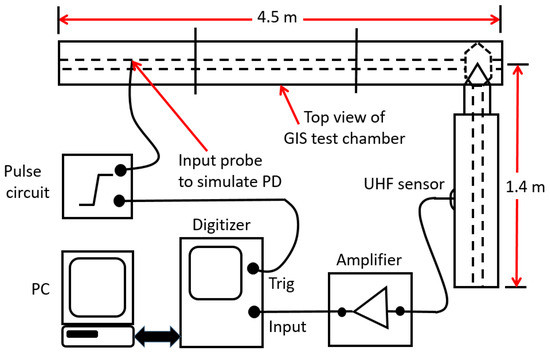
Figure 12.
Instrumentation for PD measurements and a typical setup for modeling the measurement on GIS [124].
4.1.2. PD Detection in Transformer
The UHF PD detection technique is widely employed for routine maintenance and monitoring of high-voltage transformers. When applied to transformers, the UHF PD detection method benefits from low noise levels due to effective shielding. Additionally, the attenuation of signals in oil insulation is minimal, resulting in excellent measurement sensitivity in on-site conditions. In laboratory settings, the PD measurement setup for transformers typically involves a partially enclosed metallic tank measuring 1.0 m × 0.5 m × 0.5 m. The setup includes a needle sphere PD source and two similar disc sensors. The transient reading record has a bandwidth of approximately 3 GHz, and no additional amplification is necessary as the output quality from the pre-amplifier is satisfactory. The UHF technique has gained popularity for testing power transformers, offering superior sensitivity compared to AE methods [125]. A typical UHF monitoring system setup, shown in Figure 13a, consists of filtered and amplified signals from the sensors, which are then detected and digitized. The digitization process enables dynamic utilization of the signals, and the phase reference and clock information are logged along with the digitized data. The recorded PD pulses are considered to originate from a point source in real time, with the amplitude of the pulse calibrated against the UHF signal energy [62]. The coupling capacitor does this by enabling UHF transmissions to get through while filtering out the low-frequency noise based on Figure 13b. Since the testing tools are corona free, they can be connected to transformers of various power.
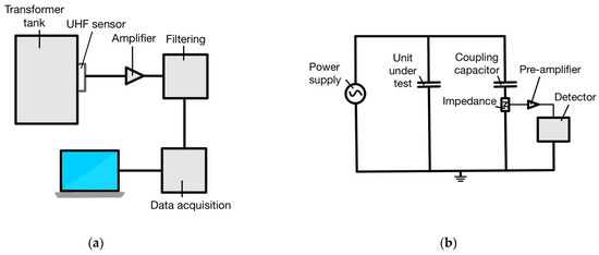
Figure 13.
(a) The basic UHF monitoring system for PD and its guiding principle and (b) principle of a typical ultra high frequency [62].
4.2. Mechanism in Chemical Sensors
Chemical changes in the composition of insulating materials in transformers and GIS can be utilized for the chemical detection of PD signals. By observing these changes, it is possible to identify PD activity occurring within the equipment. The use of DGA or HPLC is used to analyze the chemical characteristics. The DGA study sought to determine the concentrations of several gases, including hydrogen, ethylene, acetylenes, carbon dioxide, and methane, in a sample of fluid from an oil-cooling transformer’s container or gas from the GIS [126]. These levels must not be higher than those specified in the occurrence of oil insulation or insulation material malfunction. Unfortunately, no scientific or experimental link or calibration has been established between DGA readings, dissolved gas levels, and fault types. The HPLC test quantifies the by-products of transformer or GIS insulation breakdown. When a transformer’s insulation fails, glucose is produced. Real-time monitoring of PD byproducts through the collection and analysis of sufficient quantities of insulation breakdown byproducts is time-consuming. Due to the lack of a consistent association between the glucose concentration emitted during insulation failure and the kind and severity of high voltage transformer malfunction, both HPLC and DGA tests are prone to the same degree of ambiguity. Inaccurate localization of the PD signal source and evaluation of insulation deterioration are also beyond the chemical approach’s capabilities. As a result, the chemical technique cannot provide real-time online monitoring.
PD Detection in Transformer
Figure 14a illustrates a hydrogen–oil detector. A portable gas chromatograph is connected to a semipermeable membrane, which is then located in the transformer’s oil tank. The portable gas chromatograph can test the concentration of hydrogen gas at predetermined time intervals. The fuel cell type detectors are used in the second profit-oriented version of the DGA testing for power transformers, as illustrated in Figure 14 [127].
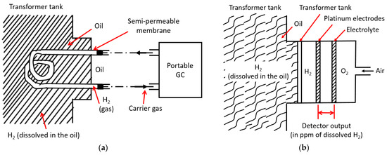
Figure 14.
The two most common chemical methods for detecting PD, including (a) hydrogen-in-oil detector and (b) continuous monitoring [127].
4.3. Mechanism in Acoustic Sensors
The PZT ultrasonic sensor is sensitive to signals generated by PD in oil at wideband frequencies (from 10 kHz to 500 kHz). Most of the PD detection and monitoring devices use acoustic sensors, which are usually located far from high-voltage hardware. A PD coupler is required for acoustic detection equipment that detects harmonic distortion. The vaporization of the oil’s molecule results in a mechanical energy explosion, in which a pressure field is produced from which a sonic wave emerges. The capacitive properties of PD are unimportant when the acoustic technique is used due to its insensitive to changes in the capacitance of the test object [123]. When comparing the two PD signal detection systems, the acoustic one has a lower sensitivity than the electrical one. On the other hand, by measuring the time differences of arrival (TOA) of acoustic signals at multiple sensors deployed, it is possible to estimate the location where partial discharge occurs.
4.3.1. PD Detection in Gas-Insulated Switchgear
The GIS is designed as a sealed structure, filled with pressurized gas. As an insulator, SF6 gas is more effective than air because it exhibits higher dielectric strength, acts as an electronegative medium to capture free electrons and prevent electrical discharges, is non-flammable, possesses an extremely stable molecular structure, and serves as a cooling medium. The acoustic emission (AE) reflected off the metal walls of the GIS can be used to discern PD. The acoustic waves created by PD have a wide frequency range (20 kHz–250 kHz) and a radical symmetry. The PD measurement at GIS can be conducted using a touch sensor, as shown in Figure 15.
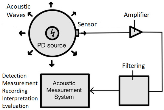
Figure 15.
The touch sensor practically used to detect PD in GIS.
4.3.2. PD Detection in Transformer
The maximal temperature and insulation tolerance are crucial factors in determining a transformer’s operational lifespan, which has a significant economic impact on the operation of an electrical power network. Any malfunctioning transformer reduces network dependability and increases maintenance expenses. Before analysis, the acoustic signals generated by partial discharges PD in oil-cooled transformers are detected using a decoupler and amplified with a low-noise amplifier to assure high sensitivity. In laboratory tests, PD must be simulated using three varieties of electrode structures: plane–plane, needle–plane, and wire–wire. When these structures are stimulated, they simulate partial discharges in the transformer’s oil-filled walls. Increasing the alternating current (AC) voltage from 0 to 50 kV rms (refer to Figure 16) induces PD in the oil-immersed electrode system. On the outer surface of the transformer tank, an acoustic emission sensor is installed to detect the PD-induced acoustic signals. These signals are then transmitted to an oscilloscope via a low-noise amplifier with a frequency bandwidth of 1.6 kHz to 1.6 MHz and a 3 dB mid-band frequency bandwidth. Depending on the electrode system, the frequency ranges of the acoustic signals range from 45 kHz to 25 kHz for the plane–plane configuration, 60 kHz to 279 kHz for the needle–plane configuration, and 50 kHz to 180 kHz for the wire–wire configuration. Specifically, the detected frequencies for the needle–plane electrode were 145 kHz, and for the wire–wire electrode, they were 121 kHz. Using three acoustic sensors to capture the PD-induced acoustic signals, the location of the PD can be determined within a 1% margin of error [124].
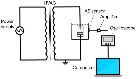
Figure 16.
The experimental setup for PD measurement by replicating the PD stimulate in a transformer using a PD test cell [124].
4.4. Mechanism in Optical Sensors
Fiber optic cable has long been utilized as a sensor because of its many advantages, including its resistance to protection against chemical decay, electrical sparks, a wide variety of measures, and response, tolerance to high sensitivity, wide bandwidth, extreme temps, and compact size. Detection of optical properties such as wavelength, intensity, polarity, and phase are based on minute changes in optical properties. As a result, four types of optical sensors can be utilized for various applications, including spectral analysis, intensity measurements, polarization, and interferometry. The fiber optic acoustic sensor is one such sensor that combines acoustic and optical technologies. It includes a fiber optic intrinsic transducer, such as a Mach–Zehnder or Michelson interferometer, multimode fiber, and a fiber optic external device, such as a Fabry–Perot interferometric sensor. The detection method of the fiber optic acoustic sensors relies on leveraging the photo elastic effect of silica fiber to convert acoustic signals into optical signals. When a sound wave intersects with fiber optics, its shape is distorted. This distortion will influence fiber length and refractive index. As a result of this change, a passing laser beam may undergo some modulation. The silica fiber’s low photo elastic effect to be increased in improving the sensitivity.
PD Detection in Transformer
In general, PD originated inside a huge oil-filled power transformer, where its detection is notoriously difficult to be performed by using an external acoustic sensor. To spot and determine the PD with sufficient sensitivity, an acoustic sensor, for example, a fiber-optic coil, is required. A previous approach to acoustic detection involved utilizing fiber optics essential interferometers, such as the fiber Michelson and Mach–Zehnder interferometers. These fiber sensors employed a single mode fiber and laser technology. A fiber coupler divides the light into two strands with intensity differences of 3 dB from the original source. One fiber serves as a reference, while the other as a sensor. To generate noise signals, either transmission, as in the Michelson interferometer, or reflection, as in the Mach–Zehnder interferometer, merges the light from the two shafts. Although the source light is in the reference shaft, the sensor arm is vulnerable to PD-induced sonic wave disturbance. The sonic wave will have affected the initial light source as viewed by the detecting arm. The essential fiber interferometer sensor achieves excessively high sensitivity when a long fiber is utilized in the detection procedure. In Figure 17, an illustration of the experimental setup is shown for monitoring PD signals using a submerged coil of fiber optic sensor into oil inside the transformer. The light source in the system is a single-mode optic fiber, an optoelectronic transducer that converts a light beam into an electrical signal, two electrodes, and a high voltage input to generate simulated PD events that would produce acoustic emission. The phase of the optical signal would alter if an acoustic wave struck the fiber optic sensor coil. As a by-product of consecutive phase differences, the visible light in the sensor coil has the tendency to be modulated. The electrical signal created by the sensor coil’s light source is then amplified and inspected [125].
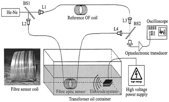
Figure 17.
The illustration of Mach–Zehnder interferometer in an experiment to detect PD in the laboratory.
The Fabry–Perot interferometric sensor has a wide range of applications, including the detection of acoustic waves generated due to PD events [126]. It consists of two reflective surfaces that form a small sensing element known as Fabry–Perot cavity. The operational principle of the Fabry–Perot interferometer sensor is depicted in Figure 18. The 22 coupler was used with a light source. A single-mode fiber is attached to one of the coupler arms and fused to the sensor head. The optical signal is transformed into an electrical signal via a photodetector connected to the opposite arm simultaneously. The electrical signal undergoes amplification before being sent to a high-speed signal processor or a digital oscilloscope. The silica diaphragm and single-mode fiber Fabry–Perot interferometer sensor is built within the sensor lead. The Fabry–Perot interferometer sensor’s capacity to track acoustic signals produced by partial discharge inside the transformer has been proven in multiple testing.
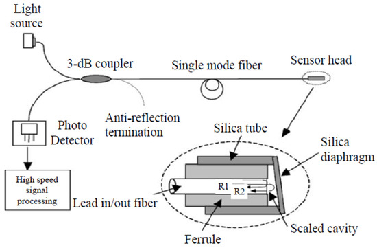
Figure 18.
The illustration of the principle of the fiber optic acoustic sensor [113].
On the other hand, in addition to those aforementioned earlier in the manuscript, Table 2 and Table 3 show the recent timelines of partial discharge detection activities in power transformers and gas-insulated switchgear, respectively.
Table 2.
Recent timeline of partial discharge activities inside power transformer.
Table 3.
Recent timeline of partial discharge activities inside gas-insulated switchgear.
5. Challenges and Future Directions of PD Detection in Transformers and GIS
PD detection in transformers and GIS is a crucial aspect of maintenance and reliability in power systems. PD is the localized breakdown of insulation materials, which can lead to equipment failure if left undetected. Detecting and monitoring PD is essential for ensuring the safe and efficient operation of transformers and GIS.
Here are some challenges and future directions in the field of PD detection for transformers and GIS:
- i.
- Sensitivity and accuracy: One of the primary challenges is achieving high sensitivity and accuracy in PD detection. PD signals can be weak and easily masked by noise, making it challenging to detect and distinguish them from other signals. Future directions involve developing advanced signal processing techniques, pattern recognition algorithms, and machine learning approaches to enhance sensitivity and reduce false alarms.
- ii.
- Online monitoring: Currently, PD detection in transformers and GIS is predominantly performed through offline testing, which involves shutting down the equipment. However, there is a growing need for online monitoring systems that can continuously detect and monitor PD during normal operation. Future directions involve developing non-intrusive, online PD detection techniques that can provide real-time monitoring without disrupting the system.
- iii.
- Sensor placement and installation: Optimal sensor placement is crucial for effective PD detection. Transformers and GIS have complex structures, and it can be challenging to determine the best locations for sensors to capture PD signals accurately. Future directions involve conducting research on optimal sensor placement techniques using simulations, advanced modeling, and experimental studies to improve the reliability and sensitivity of PD detection.
- iv.
- UHF and optical methods: Ultra-High-Frequency (UHF) and optical methods are emerging as promising techniques for PD detection. UHF sensors can capture PD signals in the radio frequency range, while optical methods use fiber optic sensors for detection. These approaches offer advantages such as higher sensitivity, immunity to electromagnetic interference, and the ability to cover a large area. Future directions involve further developing and refining these techniques to make them more practical, cost-effective, and suitable for deployment in transformers and GIS.
- v.
- Condition monitoring and data analytics: PD detection is not limited to identifying the presence of PD; it also involves analyzing the data to assess the condition of the equipment. Future directions involve integrating PD detection with advanced data analytics, such as predictive maintenance and fault diagnosis algorithms. This will enable a better understanding of PD behavior, identification of potential failure modes, and timely decision making for maintenance and asset management.
- vi.
- Standardization and guidelines: Developing standardized procedures, guidelines, and best practices for PD detection in transformers and GIS is important for ensuring consistency and reliability across different utilities and industries. Future directions involve establishing international standards and guidelines based on extensive research, testing, and collaborative efforts among experts and industry stakeholders.
By addressing these challenges and exploring future directions, the field of PD detection in transformers and GIS can make significant advancements in terms of reliability, safety, and efficiency of power systems.
6. Conclusions
Monitoring the PD phenomenon in high-voltage power systems and equipment is considered a necessary measurement for the preventive maintenance of equipment that is under operation or for the performance assessment of new equipment manufactured by the industries. Hence, the capability and suitability of the use of appropriate sensors with certain properties and methods of PD measurement in obtaining reliable outcomes of PD measurement on power transformers and GIS is the gap that potentially can be gratified and included to be the critical concerns in extending the research in the future. Based on the collective review of PD detection on power transformers and GIS, it has been found that advanced online monitoring technology was preferred in PD detection, especially the technique that uses directly integrated sensors on high-voltage equipment. This is because the online monitoring technique allowed the PD detection to be conducted without the need of isolating the power system and giving out realistic results based on the equipment’s actual peripherals. Therefore, the research on designing and improving the capability of sensors can be summarized as an impactful study for future research on PD detection, including the technique to enhance sensitivity and accuracy in obtaining high precision of PD data collection.
The UHF detection approach is currently an excellent tool for identifying PD in power transformers and GIS. Capturing and analyzing the electromagnetic signals released by PD occurrences is required for UHF detection. It employs UHF antennas that are purpose-built to detect and receive these signals. The advantage of UHF monitoring is its capacity to detect PD actions early on, allowing for timely maintenance and prevention of future deterioration. To ensure effective detection, UHF sensors can be carefully placed near crucial portions of the equipment. UHF detection has a number of advantages, including high sensitivity, a broad frequency bandwidth, and the ability to detect PD in both power transformers and GIS. It is a widely accepted and reliable method for PD detection in these types of electrical equipment. However, it is interesting to note that the UHF PD detection method is affected by electromagnetic interference and could be a source of pollution for the power grids and equipment. Therefore, non-electrical measurement methods are gradually attracting more attention because they are not prone to electromagnetic interference. Please note that the choice of PD detection method should consider the specific requirements and characteristics of the equipment being monitored. Consulting industry standards and experts in the field is recommended to determine the most suitable method for a particular application.
Author Contributions
Conceptualization, F.Z. and Z.F.; methodology, F.Z. and Z.F.; software, F.Z. and M.J.; validation, F.Z., N.M.S. and Z.F.; formal analysis, F.Z., Z.F. and N.M.S.; investigation, Z.F. and F.Z.; resources, F.Z. and Z.Y.; data curation, Z.F; writing—original draft preparation, Z.F. and F.Z; writing—review and editing, F.Z. and N.M.S.; visualization, Z.F. and Z.Y.; supervision, F.Z. and M.H.A.; project administration, O.A., H.A.M. and M.K.A.R.; funding acquisition, F.Z. and Z.Y. All authors have read and agreed to the published version of the manuscript.
Funding
This research received no external funding.
Data Availability Statement
Not applicable.
Acknowledgments
The authors would like to acknowledge the sponsorship from the Higher Institution Centre of Excellence (HICOE), the Ministry of Higher Education Malaysia through the Wireless Communication Centre (WCC), Universiti Teknologi Malaysia (UTM) Vot. No. R.J090301.7823.4J610. This work was also supported by the Universiti Teknologi Malaysia (UTM) under the UTM Encouragement Research grant (20J65), UTMShine Batch 6 Grants (09G97), and partially sponsored by the Faculty of Engineering, Multimedia University, Cyberjaya (MMU).
Conflicts of Interest
The authors declare no conflict of interest.
References
- Akbari, A.; Werle, P.; Borsi, H.; Gockenbach, E. Transfer function-based partial discharge localization in power transformers: A feasibility study. IEEE Electr. Insul. Mag. 2002, 18, 22–32. [Google Scholar] [CrossRef]
- Meira, M.; Ruschetti, C.R.; Álvarez, R.E.; Verucchi, C.J. Power transformers monitoring based on electrical measurements: State of the art. IET Gener. Transm. Distrib. 2018, 12, 2805–2815. [Google Scholar] [CrossRef]
- Abbasi, A.R.; Mahmoudi, M.R.; Avazzadeh, Z. Diagnosis and clustering of power transformer winding fault types by cross-correlation and clustering analysis of FRA results. IET Gener. Transm. Distrib. 2018, 12, 4301–4309. [Google Scholar] [CrossRef]
- Saponara, S.; Fanucci, L.; Bernardo, F.; Falciani, A. Predictive Diagnosis of High-Power Transformer Faults by Networking Vibration Measuring Nodes with Integrated Signal Processing. IEEE Trans. Instrum. Meas. 2016, 65, 1749–1760. [Google Scholar] [CrossRef]
- Duval, M. A review of faults detectable by gas-in-oil analysis in transformers. IEEE Electr. Insul. Mag. 2002, 18, 8–17. [Google Scholar] [CrossRef]
- Faiz, J.; Soleimani, M. Dissolved gas analysis evaluation in electric power transformers using conventional methods a review. IEEE Trans. Dielectr. Electr. Insul. 2017, 24, 1239–1248. [Google Scholar] [CrossRef]
- Kawaguchi, Y.; Yanabu, S. Partial-Discharge Measurement on High-Voltage Power Transformers. IEEE Trans. Power Appar. Syst. 1969, PAS-88, 1187–1194. [Google Scholar] [CrossRef]
- Zhang, S. Analysis of Some Measurement Issues in Bushing Power Factor Tests in the Field. IEEE Trans. Power Deliv. 2006, 21, 1350–1356. [Google Scholar] [CrossRef]
- Hashemnia, N.; Abu-Siada, A.; Islam, S. Detection of power transformer bushing faults and oil degradation using frequency response analysis. IEEE Trans. Dielectr. Electr. Insul. 2016, 23, 222–229. [Google Scholar] [CrossRef]
- Secic, A.; Krpan, M.; Kuzle, I. Vibro-Acoustic Methods in the Condition Assessment of Power Transformers: A Survey. IEEE Access 2019, 7, 83915–83931. [Google Scholar] [CrossRef]
- Wang, M.; Vandermaar, A.; Srivastava, K. Review of condition assessment of power transformers in service. IEEE Electr. Insul. Mag. 2002, 18, 12–25. [Google Scholar] [CrossRef]
- Oliveira, M.O.; Bretas, A.S. Application of Discrete Wavelet Transform for differential protection of power transformers. In Proceedings of the 2009 IEEE Bucharest PowerTech, Bucharest, Romania, 28 June–2 July 2009; pp. 1–8. [Google Scholar] [CrossRef]
- Yao, C.; Zhao, Z.; Mi, Y.; Li, C.; Liao, Y.; Qian, G. Improved Online Monitoring Method for Transformer Winding Deformations Based on the Lissajous Graphical Analysis of Voltage and Current. IEEE Trans. Power Deliv. 2015, 30, 1965–1973. [Google Scholar] [CrossRef]
- Saha, T.K. Review of modern diagnostic techniques for assessing insulation condition in aged transformers. IEEE Trans. Dielectr. Electr. Insul. 2003, 10, 903–917. [Google Scholar] [CrossRef]
- Cardoso, A.; Oliveira, L.M. Condition monitoring and diagnostics of power transformers. Int. J. COMADEM 1999, 2, 5–11. [Google Scholar]
- Tenbohlen, S.; Coenen, S.; Djamali, M.; Müller, A.; Samimi, M.H.; Siegel, M. Diagnostic Measurements for Power Trans-formers. Energies 2016, 9, 347. [Google Scholar] [CrossRef]
- Fu, Q.; Zhu, J.; Mao, Z.-H.; Zhang, G.; Chen, T. Online Condition Monitoring of Onboard Traction Transformer Core Based on Core-Loss Calculation Model. IEEE Trans. Ind. Electron. 2017, 65, 3499–3508. [Google Scholar] [CrossRef]
- Christina, A.; Salam, M.A.; Rahman, Q.M.; Wen, F.; Ang, S.P.; Voon, W. Causes of transformer failures and diagnostic methods—A review. Renew. Sustain. Energy Rev. 2018, 82, 1442–1456. [Google Scholar]
- Han, Y.; Song, Y. Condition monitoring techniques for electrical equipment-a literature survey. IEEE Trans. Power Deliv. 2003, 18, 4–13. [Google Scholar] [CrossRef]
- Bigdeli, M.; Vakilian, M.; Rahimpour, E. Transformer winding faults classification based on transfer function analysis by support vector machine. IET Electr. Power Appl. 2012, 6, 268–276. [Google Scholar] [CrossRef]
- Li, S.; Li, J. Condition monitoring and diagnosis of power equipment: Review and prospective. High Volt. 2017, 2, 82–91. [Google Scholar] [CrossRef]
- Medeiros, R.P.; Costa, F.B.; Silva, K.M. Power Transformer Differential Protection Using the Boundary Discrete Wavelet Transform. IEEE Trans. Power Deliv. 2015, 31, 2083–2095. [Google Scholar] [CrossRef]
- Fuhr, J. Procedure for identification and localization of dangerous PD sources in power transformers. IEEE Trans. Dielectr. Electr. Insul. 2005, 12, 1005–1014. [Google Scholar] [CrossRef]
- Bhatt, S.M.; Kumar, D.; Patel, K. Partial Discharge Analysis in Time and Time-Frequency Domain of Solid Dielectric in Power Transformer. In Proceedings of the 2018 5th IEEE Uttar Pradesh Section International Conference on Electrical, Electronics and Computer Engineering (UPCON), Gorakhpur, India, 2–4 November 2018; pp. 1–5. [Google Scholar] [CrossRef]
- Kumar, A.S.; Gupta, R.P.; Udayakumar, K.; Venkatasami, A. Online partial discharge detection and location techniques for condition monitoring of power transformers: A review. In Proceedings of the 2008 International Conference on Condition Monitoring and Diagnosis, Beijing, China, 21–24 April 2008; pp. 927–931. [Google Scholar] [CrossRef]
- Darwish, A.; Refaat, S.S.; Toliyat, H.A.; Abu-Rub, H. On the Electromagnetic Wave Behavior Due to Partial Discharge in Gas Insulated Switchgears: State-of-Art Review. IEEE Access 2019, 7, 75822–75836. [Google Scholar] [CrossRef]
- Liao, R.-J.; Yang, L.-J.; Li, J.; Grzybowski, S. Aging condition assessment of transformer oil-paper insulation model based on partial discharge analysis. IEEE Trans. Dielectr. Electr. Insul. 2011, 18, 303–311. [Google Scholar] [CrossRef]
- Fuhr, J.; Aschwanden, T. Identification and localization of PD-sources in power-transformers and power-generators. IEEE Trans. Dielectr. Electr. Insul. 2017, 24, 17–30. [Google Scholar] [CrossRef]
- Mor, A.R.; Heredia, L.C.; Harmsen, D.; Muñoz, F. A new design of a test platform for testing multiple partial discharge sources. Int. J. Electr. Power Energy Syst. 2018, 94, 374–384. [Google Scholar] [CrossRef]
- Rubio-Serrano, J.; Rojas-Moreno, M.V.; Posada, J.; Martínez-Tarifa, J.M.; Robles, G.; Garcia-Souto, J.A. Electro-acoustic detection, identification and location of partial discharge sources in oil-paper insulation systems. IEEE Trans. Dielectr. Electr. Insul. 2012, 19, 1569–1578. [Google Scholar] [CrossRef]
- Braunlich, R.; Hassig, M.; Fuhr, J.; Aschwanden, T. Assessment of insulation condition of large power transformers by on-site electrical diagnostic methods. In Proceedings of the Conference Record of the 2000 IEEE International Symposium on Electrical Insulation (Cat. No.00CH37075), Anaheim, CA, USA, 5 April 2000; pp. 368–372. [Google Scholar] [CrossRef]
- Yaacob, M.M.; Alsaedi, M.A.; Rashed, J.R.; Dakhil, A.M.; Atyah, S.F. Review on partial discharge detection techniques related to high voltage power equipment using different sensors. Photon-Sens. 2014, 4, 325–337. [Google Scholar] [CrossRef]
- Khan, Q.; Refaat, S.S.; Abu-Rub, H.; Toliyat, H.A. Partial discharge detection and diagnosis in gas insulated switchgear: State of the art. IEEE Electr. Insul. Mag. 2019, 35, 16–33. [Google Scholar] [CrossRef]
- Sinaga, H.H.; Phung, B.T.; Blackburn, T.R. Partial discharge localization in transformers using UHF detection method. IEEE Trans. Dielectr. Electr. Insul. 2012, 19, 1891–1900. [Google Scholar] [CrossRef]
- Chen, M.-K.; Chen, J.-M.; Cheng, C.-Y. Partial discharge detection by RF coil in 161 kV power transformer. IEEE Trans. Dielectr. Electr. Insul. 2014, 21, 1405–1414. [Google Scholar] [CrossRef]
- Jahangir, H.; Akbari, A.; Werle, P.; Szczechowski, J. UHF PD measurements on power transformers-advantages and limitations. IEEE Trans. Dielectr. Electr. Insul. 2017, 24, 3933–3940. [Google Scholar] [CrossRef]
- Ariannik, M.; Azirani, M.A.; Werle, P.; Azirani, A.A. UHF Measurement in Power Transformers: An Algorithm to Optimize Accuracy of Arrival Time Detection and PD Localization. IEEE Trans. Power Deliv. 2019, 34, 1530–1539. [Google Scholar] [CrossRef]
- Beura, C.P.; Beltle, M.; Tenbohlen, S. Positioning of UHF PD Sensors on Power Transformers Based on the Attenuation of UHF Signals. IEEE Trans. Power Deliv. 2019, 34, 1520–1529. [Google Scholar] [CrossRef]
- Biswas, S.; Koley, C.; Chatterjee, B.; Chakravorti, S. A methodology for identification and localization of partial discharge sources using optical sensors. IEEE Trans. Dielectr. Electr. Insul. 2012, 19, 18–28. [Google Scholar] [CrossRef]
- Razzaq, A.; Zainuddin, H.; Hanaffi, F.; Chyad, R.M. Transformer oil diagnostic by using an optical fibre system: A review. IET Sci. Meas. Technol. 2019, 13, 615–621. [Google Scholar] [CrossRef]
- Baug, A.; Choudhury, N.R.; Ghosh, R.; Dalai, S.; Chatterjee, B. Identification of single and multiple partial discharge sources by optical method using mathematical morphology aided sparse representation classifier. IEEE Trans. Dielectr. Electr. Insul. 2017, 24, 3703–3712. [Google Scholar] [CrossRef]
- Refaat, S.S.; Sayed, M.; Shams, M.A.; Mohamed, A. A review of partial discharge detection techniques in power transformers. In Proceedings of the 2018 Twentieth International Middle East Power Systems Conference (MEPCON), Cairo, Egypt, 18–20 December 2018. [Google Scholar] [CrossRef]
- Hooshmand, R.A.; Parastegari, M.; Yazdanpanah, M. Simultaneous location of two partial discharge sources in power transformers based on acoustic emission using the modified binary partial swarm optimisation algorithm. IET Sci. Meas. Technol. 2013, 7, 119–127. [Google Scholar] [CrossRef]
- Wang, Y.B.; Fan, Y.H.; Qin, S.R.; Chang, D.G.; Shao, X.J.; Mu, H.B.; Zhang, G.J. Partial discharge localisation methodology for power transformers based on improved acoustic propagation route search algorithm. IET Sci. Meas. Technol. 2018, 12, 1023–1030. [Google Scholar] [CrossRef]
- Shanker, T.B.; Nagamani, H.N.; Antony, D.; Punekar, G.S. Effects of Transformer-Oil Temperature on Amplitude and Peak Frequency of Partial Discharge Acoustic Signals. IEEE Trans. Power Deliv. 2018, 33, 3227–3229. [Google Scholar] [CrossRef]
- Wang, Y.-B.; Chang, D.-G.; Fan, Y.-H.; Zhang, G.-J.; Zhan, J.-Y.; Shao, X.-J.; He, W.-L. Acoustic localization of partial discharge sources in power transformers using a particle-swarm-optimization-route-searching algorithm. IEEE Trans. Dielectr. Electr. Insul. 2017, 24, 3647–3656. [Google Scholar] [CrossRef]
- Dai, J.; Song, H.; Sheng, G.; Jiang, X. Dissolved gas analysis of insulating oil for power transformer fault diagnosis with deep belief network. IEEE Trans. Dielectr. Electr. Insul. 2017, 24, 2828–2835. [Google Scholar] [CrossRef]
- Mackenzie, E.; Crossey, J.; DePablo, A.; Ferguson, W. On-line monitoring and diagnostics for power transformers. In Proceedings of the 2010 IEEE International Symposium on Electrical Insulation, San Diego, CA, USA, 6–9 June 2010; IEEE: New York, NY, USA, 2010. [Google Scholar]
- Faiz, J.; Soleimani, M. Assessment of computational intelligence and conventional dissolved gas analysis methods for transformer fault diagnosis. IEEE Trans. Dielectr. Electr. Insul. 2018, 25, 1798–1806. [Google Scholar] [CrossRef]
- Wang, X.; Li, B.; Roman, H.; Russo, O.; Chin, K.; Farmer, K. Acousto-optical PD Detection for Transformers. IEEE Trans. Power Deliv. 2006, 21, 1068–1073. [Google Scholar] [CrossRef]
- Si, W.; Fu, C.; Yuan, P. An Integrated Sensor With AE and UHF Methods for Partial Discharges Detection in Transformers Based on Oil Valve. IEEE Sens. Lett. 2019, 3, 1–3. [Google Scholar] [CrossRef]
- Lu, Y.; Qiu, Z.; Liao, C.; Li, T.; Wu, Z.; Hu, Y. The Application of High Frequency and Ultra High Frequency Partial Discharge Detection to Gas Insulated Switchgear. In Proceedings of the 2022 4th Asia Energy and Electrical Engineering Symposium (AEEES), Chengdu, China, 25–28 March 2022; pp. 712–716. [Google Scholar] [CrossRef]
- Sinaga, H.; Phung, B.; Blackburn, T. Partial discharge measurement for transformer insulation using wide and narrow band methods in ultra high frequency range. In Proceedings of the 2009 Australasian Universities Power Engineering Conference, Adelaide, Australia, 27–30 September 2009; IEEE: New York, NY, USA, 2010. [Google Scholar]
- Shi, R.; Li, S.; Li, Q.; Liu, B.; Ma, S.; Wu, L. The application of transient earth voltage in the partial discharge of power transformers. In Proceedings of the 2017 1st International Conference on Electrical Materials and Power Equipment (ICEMPE), Xi’an, China, 14–17 May 2017; pp. 202–206. [Google Scholar] [CrossRef]
- Ren, M.; Dong, M.; Ren, Z.; Li, H.; Qiu, A. Application of Transient Earth Voltage method in PD detection in GIS. In Proceedings of the 2011 International Symposium on Electrical Insulating Materials, Kyoto, Japan, 6–10 September 2011; IEEE: New York, NY, USA, 2010. [Google Scholar]
- Nagamani, H.N.; Shanker, T.B.; Vaidhyanathan, V.; Neelakantan, S. Acoustic emission technique for detection and location of simulated defects in power transformers. In Proceedings of the 2005 IEEE Russia Power Tech, St. Petersburg, Russia, 27–30 June 2005; pp. 1–7. [Google Scholar] [CrossRef]
- Qi, B.; Li, C.; Hao, Z.; Geng, B.; Xu, D.; Liu, S.; Deng, C. Partial discharge detection for GIS: A comparison between UHF and acoustic methods. In Proceedings of the 2010 IEEE International Symposium on Electrical Insulation, San Diego, CA, USA, 6–9 June 2010; pp. 1–5. [Google Scholar] [CrossRef]
- Rutgers, W.R.; Fu, Y.H. UHF PD-Detection in a power transformer. In Proceedings of the 10th International Symposium on High Voltage Engineering, Montreal, QC, Canada, 24–30 August 1997; pp. 219–222. [Google Scholar]
- Wiesbeck, W.; Sturm, C.; Soergel, W.; Porebska, M.; Adamiuk, G. Influence of Antenna Performance and Propagation Channel on Pulsed UWB Signals. In Proceedings of the 2007 International Conference on Electromagnetics in Advanced Applications, Turin, Italy, 17–21 September 2007; pp. 915–922. [Google Scholar] [CrossRef]
- Jiang, T.; Li, J.; Zheng, Y.; Sun, C. Improved Bagging Algorithm for Pattern Recognition in UHF Signals of Partial Discharges. Energies 2011, 4, 1087–1101. [Google Scholar] [CrossRef]
- Judd, M.D.; Yang, L.; Hunter, I. Partial discharge monitoring for power transformer using UHF sensors. Part 2: Field experience. IEEE Electr. Insul. Mag. 2005, 21, 5–13. [Google Scholar] [CrossRef]
- Judd, M.D.; Yang, L.; Hunter, I. Partial discharge monitoring of power transformers using UHF sensors. Part I: Sensors and signal interpretation. IEEE Electr. Insul. Mag. 2005, 21, 5–14. [Google Scholar] [CrossRef]
- Jahangir, H.; Akbari, A.; Werle, P.; Szczechowski, J. Possibility of PD calibration on power transformers using UHF probes. IEEE Trans. Dielectr. Electr. Insul. 2017, 24, 2968–2976. [Google Scholar] [CrossRef]
- Gaouda, A.M.; El-Hag, A.; Abdel-Galil, T.K.; Salama, M.M.; Bartnikas, R. On-line detection and measurement of partial discharge signals in a noisy environment. IEEE Trans. Dielectr. Electr. Insul. 2008, 15, 1162–1173. [Google Scholar] [CrossRef]
- Seo, J.; Ma, H.; Saha, T.K. A Joint Vibration and Arcing Measurement System for Online Condition Monitoring of Onload Tap Changer of the Power Transformer. IEEE Trans. Power Deliv. 2016, 32, 1031–1038. [Google Scholar] [CrossRef]
- Rahman, M.S.A.; Lewin, P.L.; Rapisarda, P. Autonomous localization of partial discharge sources within large transformer windings. IEEE Trans. Dielectr. Electr. Insul. 2016, 23, 1088–1098. [Google Scholar] [CrossRef]
- Timperley, J.E. Incipient fault identification through neutral RF monitoring of large rotating machines. IEEE Trans. Power Appar. Syst. 1983, 3, 693–698. [Google Scholar] [CrossRef]
- Giussani, R.; Cotton, I.; Sloan, R. Comparison of IEC 60270 and RF partial discharge detection in an electromagnetic noise-free environment at differing pressures. In Proceedings of the 2012 IEEE International Symposium on Electrical Insulation, San Juan, PR, USA, 10–13 June 2012; pp. 127–131. [Google Scholar] [CrossRef]
- IEEE Standard C57.113-2010 (Revision IEEE Standard C57.113-1991); IEEE Recommended Practice for Partial Discharge Measurement in Liquid-Filled Power Transformers and Shunt Reactors. IEEE: Piscataway, NJ, USA, 2010; pp. 1–47.
- Judd, M.D. Experience with UHF partial discharge detection and location in power transformers. In Proceedings of the 2011 Electrical Insulation Conference (EIC), Annapolis, MD, USA, 5–8 June 2011; IEEE: New York, NY, USA, 2011. [Google Scholar]
- IEC Int. Standard 60270; 3rd ed. High Voltage Test Techniques-Partial Discharge Measurements. IEC: Geneva, Switzerland, 2000.
- Xie, Q.; Cheng, S.; Lü, F.; Li, Y. Location of partial discharge in transformer oil using circular array of ultrasonic sensors. IEEE Trans. Dielectr. Electr. Insul. 2013, 20, 1683–1690. [Google Scholar] [CrossRef]
- Zheng, S.; Li, C.; Tang, Z.; Chang, W.; He, M. Location of PDs inside transformer windings using UHF methods. IEEE Trans. Dielectr. Electr. Insul. 2014, 21, 386–393. [Google Scholar] [CrossRef]
- Bartnikas, R. Partial discharges. Their mechanism, detection and measurement. IEEE Trans. Dielectr. Electr. Insul. 2002, 9, 763–808. [Google Scholar] [CrossRef]
- Karmakar, S.; Roy, N.K.; Kumbhakar, P. Partial discharge measurement of transformer with ICT facilities. In Proceedings of the 2009 International Conference on Power Systems, Kharagpur, India, 27–29 December 2009; pp. 1–5. [Google Scholar] [CrossRef]
- Ma, G.M.; Li, C.R.; Mu, R.D.; Jiang, J.; Luo, Y.T. Fiber Bragg grating sensor for hydrogen detection in power transformers. IEEE Trans. Dielectr. Electr. Insul. 2014, 21, 380–385. [Google Scholar] [CrossRef]
- Skelly, D. Photo-acoustic spectroscopy for dissolved gas analysis: Benefits and Experience. In Proceedings of the 2012 IEEE International Conference on Condition Monitoring and Diagnosis, Bali, Indonesia, 23–27 September 2012; pp. 29–43. [Google Scholar] [CrossRef]
- Lima, S.E.U.; Frazao, O.; Farias, R.G.; Araujo, F.M.; Ferreira, L.A.; Santos, J.L.; Miranda, V. Mandrel-Based Fiber-Optic Sensors for Acoustic Detection of Partial Discharges—A Proof of Concept. IEEE Trans. Power Deliv. 2010, 25, 2526–2534. [Google Scholar] [CrossRef]
- Sheng, J.; Wu, G.; Tong, L.; Zhou, L.; Zhang, J. Study on gas and oil separating plant used for online monitoring system of transformer. In Proceedings of the Conference Record of the 2004 IEEE International Symposium on Electrical Insulation, Indianapolis, IN, USA, 19–22 September 2004. [Google Scholar] [CrossRef]
- Sparkman, O.D.; Penton, Z.; Kitson, F.G. Gas Chromatography and Mass Spectrometry: A Practical Guide; Academic Press: Cambridge, MA, USA, 2011. [Google Scholar]
- Bakar, N.; Abu-Siada, A.; Islam, S. A review of dissolved gas analysis measurement and interpretation techniques. IEEE Electr. Insul. Mag. 2014, 30, 39–49. [Google Scholar] [CrossRef]
- Jiang, J.; Song, H.T.; Ma, G.M.; Li, C.R.; Luo, Y.T.; Wang, H.B. Dissolved hydrogen detection in power transformer based on etched fiber Bragg grating. In Proceedings of the 2015 IEEE International Instrumentation and Measurement Technology Conference (I2MTC) Proceedings, Pisa, Italy, 11–14 May 2015; IEEE: New York, NY, USA, 2015. [Google Scholar]
- Mukhtaruddin, A.; Isa, M.; Adzman, M.R.; Hasan, S.I.S.; Rohani, M.N.K.H.; Yii, C.C. Techniques on partial discharge detection and location determination in power transformer. In Proceedings of the 2016 3rd International Conference on Electronic Design (ICED), Phuket, Thailand, 11–12 August 2016; pp. 537–542. [Google Scholar] [CrossRef]
- Mak, T.; Westerwaal, R.; Slaman, M.; Schreuders, H.; van Vugt, A.; Victoria, M.; Boelsma, C.; Dam, B. Optical fiber sensor for the continuous monitoring of hydrogen in oil. Sens. Actuators B Chem. 2014, 190, 982–989. [Google Scholar] [CrossRef]
- Kalathiripi, H.; Karmakar, S. Partial discharge study in transformer oil using acoustic emission technique and UV-visible spectroscopy. In Proceedings of the 2017 3rd International Conference on Condition Assessment Techniques in Electrical Systems (CATCON), Rupnagar, India, 16–18 November 2017; pp. 361–366. [Google Scholar] [CrossRef]
- Qian, S.; Chen, H.; Xu, Y.; Su, L. High sensitivity detection of partial discharge acoustic emission within power transformer by sagnac fiber optic sensor. IEEE Trans. Dielectr. Electr. Insul. 2018, 25, 2313–2320. [Google Scholar] [CrossRef]
- Kweon, D.-J.; Chin, S.-B.; Kwak, H.-R.; Kim, J.-C.; Song, K.-B. The Analysis of Ultrasonic Signals by Partial Discharge and Noise From the Transformer. IEEE Trans. Power Deliv. 2005, 20, 1976–1983. [Google Scholar] [CrossRef]
- Boczar, T.; Cichon, A.; Borucki, S. Diagnostic expert system of transformer insulation systems using the acoustic emission method. IEEE Trans. Dielectr. Electr. Insul. 2014, 21, 854–865. [Google Scholar] [CrossRef]
- Kucera, M.; Jarina, R.; Brncal, P.; Gutten, M. Visualisation and Measurement of Acoustic Emission from Power Transformers. In Proceedings of the 2019 12th International Conference on Measurement, Smolenice, Slovakia, 27–29 May 2019. [Google Scholar] [CrossRef]
- Kim, D.-G.; Sampath, U.; Kim, H.; Song, M. A fiber optic multi-stress monitoring system for power transformer. In Proceedings of the 2017 25th Optical Fiber Sensors Conference (OFS), Jeju, Korea, 24–28 April 2017. [Google Scholar] [CrossRef]
- Sikorski, W.; Siodla, K.; Moranda, H.; Ziomek, W. Location of partial discharge sources in power transformers based on advanced auscultatory technique. IEEE Trans. Dielectr. Electr. Insul. 2012, 19, 1948–1956. [Google Scholar] [CrossRef]
- Sarkar, B.; Koley, C.; Roy, N.; Kumbhakar, P. Condition monitoring of high voltage transformers using Fiber Bragg Grating Sensor. Measurement 2015, 74, 255–267. [Google Scholar] [CrossRef]
- Zhou, J.; Zhu, M.; Yun, Y.; Tao, J.; Liu, F. Partial Discharge Optical Pulse Signal Characteristics for Corona Defect in Oil Immersed Transformer. Res. J. Appl. Sci. Eng. Technol. 2013, 5, 3052–3056. [Google Scholar] [CrossRef]
- Fabian, J.; Neuwersch, M.; Sumereder, C.; Muhr, M.; Schwarz, R. State of the Art and Future Trends of Unconventional PD-Measurement at Power Transformers. J. Energy Power Eng. 2014, 8, 1093–1098. [Google Scholar] [CrossRef][Green Version]
- Shanker, T.B.; Vaidhyanathan, V.; Mohamed, A.S. Comparison of Partial Discharge Performance of Identical Generator Transformers in a Thermal Power Station by Acoustic Emission Technique—Case Studies. In Proceedings of the 2019 International Conference on High Voltage Engineering and Technology (ICHVET), Hyderabad, India, 7–8 February 2019; pp. 1–5. [Google Scholar] [CrossRef]
- Qi, Z.; Yi, Y.; Qiaohua, W.; Zhihao, W.; Zhe, L. Study on the Online Dissolved Gas Analysis Monitor based on the Photoacoustic Spectroscopy. In Proceedings of the 2012 IEEE International Conference on Condition Monitoring and Diagnosis, Bali, Indonesia, 23–27 September 2012; pp. 433–436. [Google Scholar] [CrossRef]
- Yongfen, L.; Xiaohu, X.; Fei, D.; Xiao, T.; Yanming, L. Comparison of DOA Algorithms Applied to Ultrasonic Arrays for PD Location in Oil. IEEE Sens. J. 2014, 15, 2316–2323. [Google Scholar] [CrossRef]
- Kim, Y.-J.; Hikita, M. A proposal for hybrid PD sensor identifying absolute distance from PD source. In Proceedings of the 2013 Annual Report Conference on Electrical Insulation and Dielectric Phenomena, Chenzhen, China, 20–23 October 2013; IEEE: New York, NY, USA, 2013. [Google Scholar]
- Hauschild, W.; Lemke, E. High-Voltage Test and Measuring Techniques; Springer: Berlin/Heidelberg, Germany, 2014; Volume 1. [Google Scholar]
- Kraetge, A.; Hoek, S.; Koch, M.; Koltunowicz, W. Robust measurement, monitoring and analysis of partial discharges in transformers and other HV apparatus. IEEE Trans. Dielectr. Electr. Insul. 2013, 20, 2043–2051. [Google Scholar] [CrossRef]
- Yin, Z.; Zhang, R.; Tong, J.; Chen, X. An all-fiber partial discharge monitoring system based on both intrinsic fiber optic interferometry sensor and fluorescent fiber. In Proceedings of the 2013 International Conference on Optical Instruments and Technology: Optical Sensors and Applications, Beijing, China, 20 December 2013. [Google Scholar] [CrossRef]
- Singsathien, J.; Suwanasri, T.; Suwanasri, C.; Ruankon, S.; Fuangpian, P.; Namvong, W.; Saengsaikaew, P.; Khotsang, W. Partial discharge detection and localization of defected power cable using HFCT and UHF sensors. In Proceedings of the 2017 14th International Conference on Electrical Engineering/Electronics, Computer, Telecommunications and Information Technology (ECTI-CON), Phuket, Thailand, 27–30 June 2017; IEEE: New York, NY, USA, 2017. [Google Scholar] [CrossRef]
- Kusumoto, S.; Itoh, S.; Tsuchiya, Y.; Mukae, H.; Matsuda, S.; Takahashi, K. Diagnostic Technique of Gas Insulated Substation by Partial Discharge Detection. IEEE Trans. Power Appar. Syst. 1980, PAS-99, 1456–1465. [Google Scholar] [CrossRef]
- Ilkhechi, H.D.; Samimi, M.H. Applications of the Acoustic Method in Partial Discharge Measurement: A Review. IEEE Trans. Dielectr. Electr. Insul. 2021, 28, 42–51. [Google Scholar] [CrossRef]
- Schwarz, R.; Muhr, M.; Pack, S. Partial discharge detection in oil with optical methods. In Proceedings of the IEEE International Conference on Dielectric Liquids, 2005. ICDL, Coimbra, Portugal, 26 June–1 July 2005; pp. 245–248. [Google Scholar] [CrossRef]
- Chai, H.; Phung, B.; Mitchell, S. Application of UHF Sensors in Power System Equipment for Partial Discharge Detection: A Review. Sensors 2019, 19, 1029. [Google Scholar] [CrossRef]
- Markalous, S.M.; Tenbohlen, S.; Feser, K. Detection and location of partial discharges in power transformers using acoustic and electromagnetic signals. IEEE Trans. Dielectr. Electr. Insul. 2008, 15, 1576–1583. [Google Scholar] [CrossRef]
- Pinpart, T.; Judd, M.D. Experimental comparison of UHF sensor types for PD location applications. In Proceedings of the 2009 IEEE Electrical Insulation Conference, Montreal, QC, Canada, 31 May–3 June 2009; pp. 26–30. [Google Scholar] [CrossRef]
- Tian, Y.; Lewin, P.; Davies, A. Comparison of on-line partial discharge detection methods for HV cable joints. IEEE Trans. Dielectr. Electr. Insul. 2002, 9, 604–615. [Google Scholar] [CrossRef]
- Dukes, R.; Culpan, E. Acoustic emission: Its techniques and applications. IEE Proc. A Phys. Sci. Meas. Instrum. Manag. Educ. Rev. 1984, 131, 241–251. [Google Scholar] [CrossRef]
- Lamela-Rivera, H.; Sanahuja, C.M.; García-Souto, J.A. Detection and wavelet analysis of partial discharges using an optical fibre interferometric sensor for high-power transformers. J. Opt. A Pure Appl. Opt. 2002, 5, 66–72. [Google Scholar] [CrossRef]
- Cosgrave, J.; Vourdas, A.; Jones, G.; Spencer, J.; Murphy, M.; Wilson, A. Acoustic monitoring of partial discharges in gas insulated substations using optical sensors. IEE Proc. A Sci. Meas. Technol. 1993, 140, 369–374. [Google Scholar] [CrossRef]
- Deng, J.; Xiao, H.; Huo, W.; Luo, M.; May, R.; Wang, A.; Liu, Y. Optical fiber sensor-based detection of partial discharges in power transformers. Opt. Laser Technol. 2001, 33, 305–311. [Google Scholar] [CrossRef]
- Gorablenkow, J.; Huecker, T.; Schichler, U. Application of UHF partial discharge monitoring and expert system diagnosis. In Proceedings of the Conference Record of the 1998 IEEE International Symposium on Electrical Insulation (Cat. No. 98CH36239), Arlington, VA, USA, 7–10 June 1998; Volume 1, pp. 61–64. [Google Scholar] [CrossRef]
- Judd, M.D.; Farish, O. High bandwidth measurement of partial discharge current pulses. In Proceedings of the Conference Record of the 1998 IEEE International Symposium on Electrical Insulation (Cat. No. 98CH36239), Arlington, VA, USA, 7–10 June 1998; Volume 2, pp. 436–439. [Google Scholar] [CrossRef]
- Nattrass, D. Partial discharge measurement and interpretation. IEEE Electr. Insul. Mag. 1988, 4, 10–23. [Google Scholar] [CrossRef]
- Negm, T.S.; Refaey, M.; Hossam-Eldin, A.A. Modeling and simulation of internal Partial Discharges in solid dielectrics under variable applied frequencies. In Proceedings of the 2016 Eighteenth International Middle East Power Systems Conference (MEPCON), Cairo, Egypt, 27–29 December 2017; pp. 639–644. [Google Scholar] [CrossRef]
- Korobeynikov, S.; Ovsyannikov, A.; Ridel, A.; Karpov, D.; Lyutikova, M.; Kuznetsova, Y.; Yassinskiy, V. Study of partial discharges in liquids. J. Electrost. 2019, 103, 103412. [Google Scholar] [CrossRef]
- Montanari, G.C. On line partial discharge diagnosis of power cables. In Proceedings of the 2009 IEEE Electrical Insulation Conference, Montreal, QC, Canada, 31 May–3 June 2009; pp. 210–215. [Google Scholar] [CrossRef]
- Sarathi, R.; Giridhar, A.; Sethupathi, K. Analysis of partial discharge activity by a conducting particle in liquid nitrogen under AC voltages adopting UHF technique. Cryogenics 2010, 50, 43–49. [Google Scholar] [CrossRef]
- Shen, Z.; El-Saadany, E. Localization of partial discharges using UHF sensors in power transformers. In Proceedings of the 2006 IEEE Power Engineering Society General Meeting, Montreal, QC, Canada, 18–22 June 2006. [Google Scholar] [CrossRef]
- Kemp, I. Partial discharge plant-monitoring technology: Present and future developments. IEE Proc.-Sci. Meas. Technol. 1995, 142, 4–10. [Google Scholar] [CrossRef]
- Kil, G.-S.; Kim, I.K.; Park, D.-W.; Choi, S.-Y.; Park, C.-Y. Measurements and analysis of the acoustic signals produced by partial discharges in insulation oil. Curr. Appl. Phys. 2008, 9, 296–300. [Google Scholar] [CrossRef]
- Schwarz, R.; Judendorfer, T.; Muhr, M. Review of partial discharge monitoring techniques used in high voltage equipment. In Proceedings of the 2008 Annual Report Conference on Electrical Insulation and Dielectric Phenomena, Quebec, QC, Canada, 26–29 October 2008; IEEE: New York, NY, USA, 2008. [Google Scholar]
- Macià-Sanahuja, C.; Lamela, H.; García-Souto, J.A. Fiber optic interferometric sensor for acoustic detection of partial discharges. J. Opt. Technol. 2007, 74, 122–126. [Google Scholar] [CrossRef]
- Claus, R.O.; Gunther, M.F.; Wang, A.; Murphy, K.A. Extrinsic Fabry-Perot sensor for strain and crack opening displacement measurements from −200 to 900 degrees C. Smart Mater. Struct. 1992, 1, 237–242. [Google Scholar] [CrossRef]
- Belanger, G.; Duval, M. Monitor for Hydrogen Dissolved in Transformer Oil. IEEE Trans. Electr. Insul. 1977, EI-12, 334–340. [Google Scholar] [CrossRef]
- Zhu, M.-X.; Wang, Y.-B.; Chang, D.-G.; Zhang, G.-J.; Shao, X.-J.; Zhan, J.-Y.; Chen, J.-M. Discrimination of three or more partial discharge sources by multi-step clustering of cumulative energy features. IET Sci. Meas. Technol. 2019, 13, 149–159. [Google Scholar] [CrossRef]
- Ozgonenel, O.; Karagol, S. Power transformer protection based on decision tree approach. IET Electr. Power Appl. 2014, 8, 251–256. [Google Scholar] [CrossRef]
- Wu, M.; Cao, H.; Cao, J.; Nguyen, H.-L.; Gomes, J.B.; Krishnaswamy, S.P. An overview of state-of-the-art partial discharge analysis techniques for condition monitoring. IEEE Electr. Insul. Mag. 2015, 31, 22–35. [Google Scholar] [CrossRef]
- Zhou, H.-Y.; Ma, G.-M.; Qin, W.-Q.; Zhang, M.; Zhang, Q.; Lin, Z.-Q.; Jiang, J. A Multiplexing Optical Partial Discharge Sensing System for Power Transformer Using a Single Photodetector. IEEE Trans. Power Deliv. 2021, 36, 1911–1913. [Google Scholar] [CrossRef]
- Zhou, H.-Y.; Ma, G.-M.; Zhang, M.; Zhang, H.-C.; Li, C.-R. A High Sensitivity Optical Fiber Interferometer Sensor for Acoustic Emission Detection of Partial Discharge in Power Transformer. IEEE Sens. J. 2019, 21, 24–32. [Google Scholar] [CrossRef]
- Sharifinia, S.; Allahbakhshi, M.; Ghanbari, T.; Akbari, A.; Mirzaei, H.R. A New Application of Rogowski Coil Sensor for Partial Discharge Localization in Power Transformers. IEEE Sens. J. 2021, 21, 10743–10751. [Google Scholar] [CrossRef]
- Hashim, A.H.M.; Azis, N.; Jasni, J.; Radzi, M.A.M.; Masahiro, K.; Kamarol, M.; Yaakub, Z. Partial Discharge Localization in Oil through Acoustic Emission Technique Utilizing Fuzzy Logic. IEEE Trans. Dielectr. Electr. Insul. 2022, 29, 623–630. [Google Scholar] [CrossRef]
- Li, J.; Han, X.; Liu, Z.; Yao, X. A Novel GIS Partial Discharge Detection Sensor With Integrated Optical and UHF Methods. IEEE Trans. Power Deliv. 2016, 33, 2047–2049. [Google Scholar] [CrossRef]
- Wu, Z.; Zhang, Q.; Ma, J.; Li, X.; Wen, T. Effectiveness of on-site dielectric test of GIS equipment. IEEE Transactions on Dielectrics and Electrical Insulation. IEEE Trans. Dielectr. Electr. Insul. 2018, 25, 1454–1460. [Google Scholar] [CrossRef]
- Kim, S.-W.; Jung, J.-R.; Kim, Y.-M.; Kil, G.-S.; Wang, G. New diagnosis method of unknown phase-shifted PD signals for gas insulated switchgears. IEEE Trans. Dielectr. Electr. Insul. 2018, 25, 102–109. [Google Scholar] [CrossRef]
- Ma, G.-M.; Zhou, H.-Y.; Zhang, M.; Li, C.-R.; Yin, Y.; Wu, Y.-Y. A High Sensitivity Optical Fiber Sensor for GIS Partial Discharge Detection. IEEE Sens. J. 2019, 19, 9235–9243. [Google Scholar] [CrossRef]
- Thi, N.-D.T.; Do, T.-D.; Jung, J.-R.; Jo, H.; Kim, Y.-H. Anomaly Detection for Partial Discharge in Gas-Insulated Switchgears Using Autoencoder. IEEE Access 2020, 8, 152248–152257. [Google Scholar] [CrossRef]
- Ren, M.; Zhou, J.; Miao, J. Adopting Spectral Analysis in Partial Discharge Fault Diagnosis of GIS With a Micro Built-in Optical Sensor. IEEE Trans. Power Deliv. 2021, 36, 1237–1240. [Google Scholar] [CrossRef]
- Wu, S.-Y.; Zheng, S.-S. Detection of Partial Discharge in GIS and Transformer Under Impulse Voltage by Fluorescent Optical Fiber Sensor. IEEE Sens. J. 2021, 21, 10675–10684. [Google Scholar] [CrossRef]
- Zhang, G.; Tian, J.; Zhang, X.; Liu, J.; Lu, C. A Flexible Planarized Biconical Antenna for Partial Discharge Detection in Gas-Insulated Switchgear. IEEE Antennas Wirel. Propag. Lett. 2022, 21, 2432–2436. [Google Scholar] [CrossRef]
- Song, H.; Zhang, Z.; Tian, J.; Sheng, G.; Jiang, X. Multiscale Fusion Simulation of the Influence of Temperature on the Partial Discharge Signal of GIS Insulation Void Defects. IEEE Trans. Power Deliv. 2021, 37, 1304–1314. [Google Scholar] [CrossRef]
- Lu, B.; Huang, W.; Xiong, J.; Song, L.; Zhang, Z.; Dong, Q. The Study on a New Method for Detecting Corona Discharge in Gas Insulated Switchgear. IEEE Trans. Instrum. Meas. 2021, 71, 1–8. [Google Scholar] [CrossRef]
Disclaimer/Publisher’s Note: The statements, opinions and data contained in all publications are solely those of the individual author(s) and contributor(s) and not of MDPI and/or the editor(s). MDPI and/or the editor(s) disclaim responsibility for any injury to people or property resulting from any ideas, methods, instructions or products referred to in the content. |
© 2023 by the authors. Licensee MDPI, Basel, Switzerland. This article is an open access article distributed under the terms and conditions of the Creative Commons Attribution (CC BY) license (https://creativecommons.org/licenses/by/4.0/).