Author Contributions
Conceptualization, L.Z., J.X. and F.L.; methodology, L.Z., J.X. and J.Z.; software, F.L., J.X. and Y.R.; validation, R.S. and J.W.; formal analysis, R.S. and J.W.; investigation, L.Z., J.X., F.L. and J.Z.; resources, F.L. and J.Z.; data curation, J.X. and R.S.; writing—original draft preparation, L.Z., J.X., J.W. and Y.L.; writing—review and editing, F.L., R.S. and J.Z.; visualization, F.L., Y.L. and Y.R.; supervision, F.L., L.Z. and J.Z.; project administration, F.L. and L.Z.; funding acquisition, L.Z. and F.L. All authors have read and agreed to the published version of the manuscript.
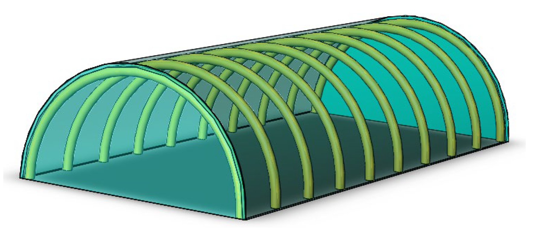
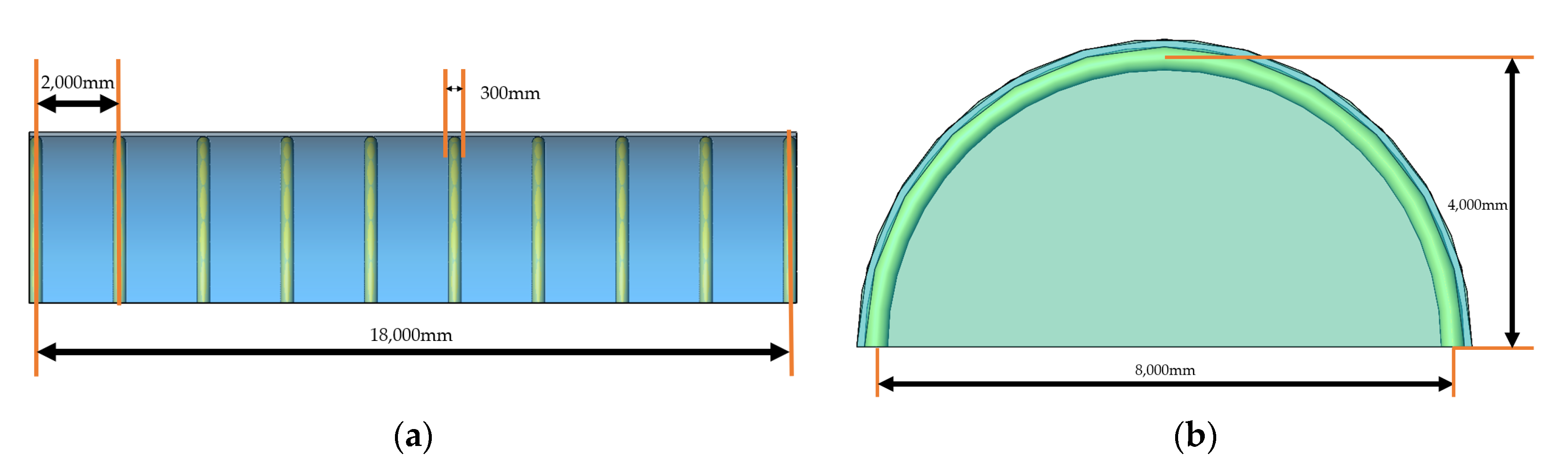
Figure 1.
Schematic diagram of structural dimensions of air-ribbed framework membrane. (a) Structure longitudinal. (b) Structure transverse.
Figure 1.
Schematic diagram of structural dimensions of air-ribbed framework membrane. (a) Structure longitudinal. (b) Structure transverse.
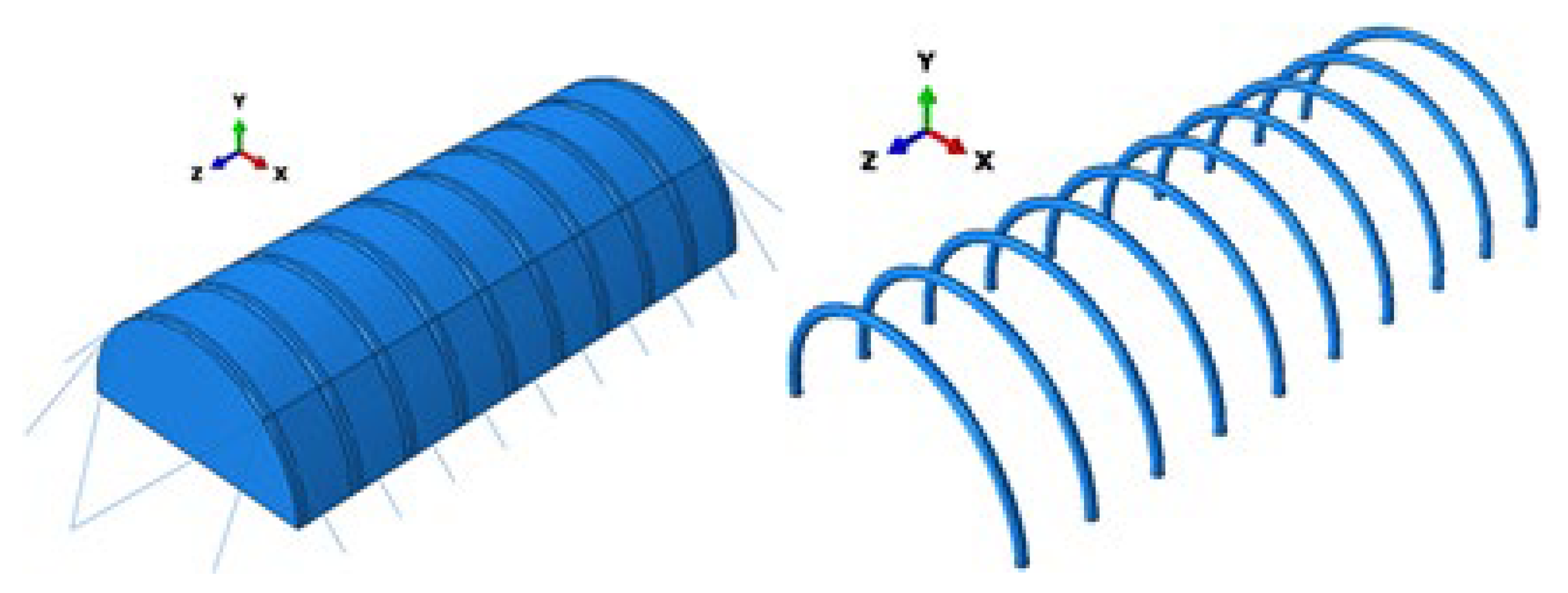
Figure 2.
Schematic diagram of the membrane structure of single-arch air frame.
Figure 2.
Schematic diagram of the membrane structure of single-arch air frame.
Figure 3.
The FE model of air-ribbed membrane structure.
Figure 3.
The FE model of air-ribbed membrane structure.
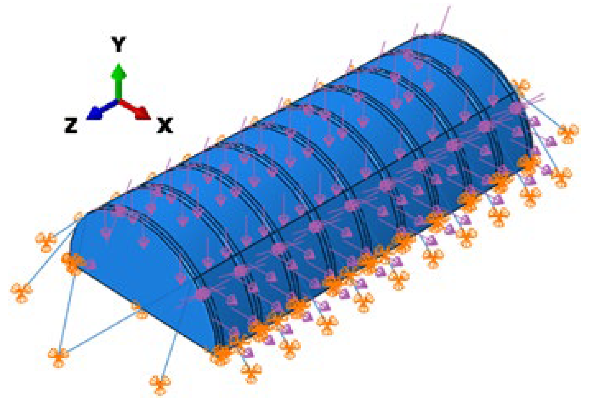
Figure 4.
The loads and boundary conditions model of the air-ribbed membrane structure. The orange element means the boundary condition and the purple element means the loading direction.
Figure 4.
The loads and boundary conditions model of the air-ribbed membrane structure. The orange element means the boundary condition and the purple element means the loading direction.
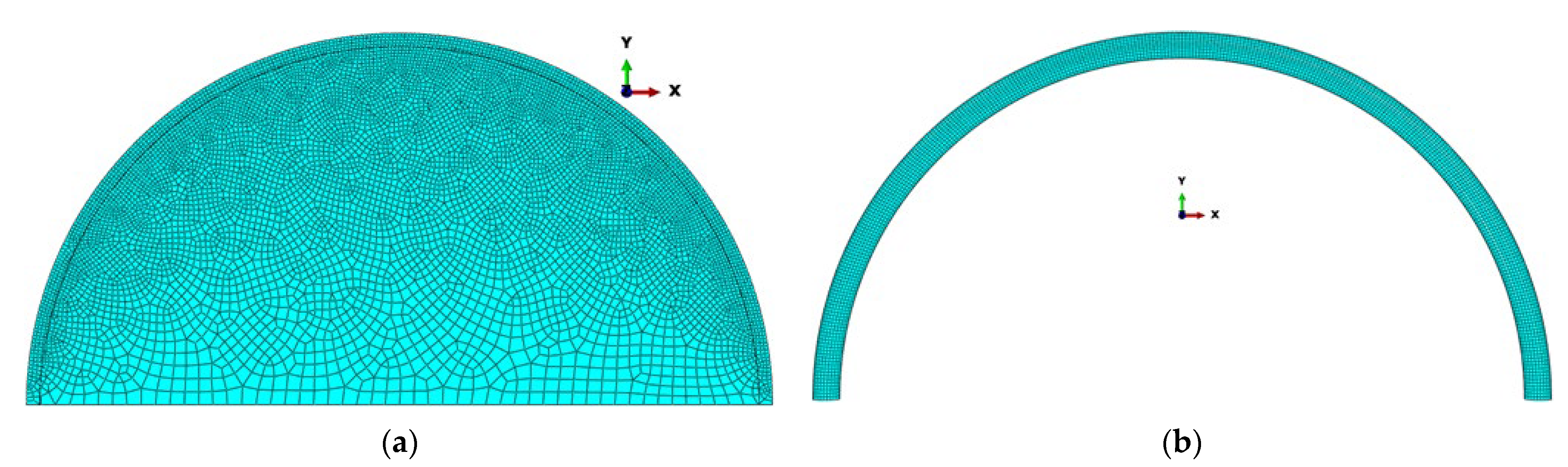
Figure 5.
The mesh model of air-ribbed membrane structure. (a) Tarpaulin meshing. (b) Air rib meshing.
Figure 5.
The mesh model of air-ribbed membrane structure. (a) Tarpaulin meshing. (b) Air rib meshing.
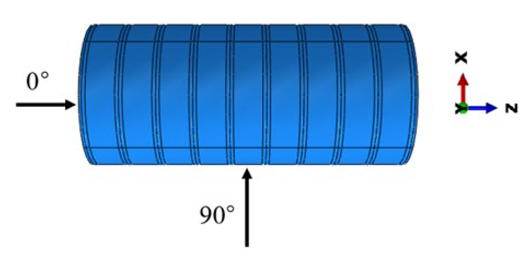
Figure 6.
The schematic diagram of wind direction.
Figure 6.
The schematic diagram of wind direction.
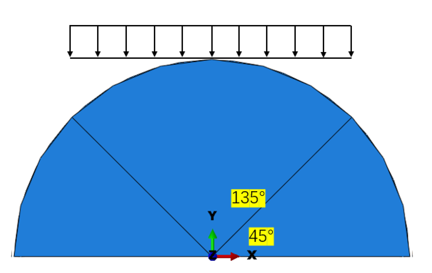
Figure 7.
The loading area of air-ribbed membrane structure under snow load.
Figure 7.
The loading area of air-ribbed membrane structure under snow load.
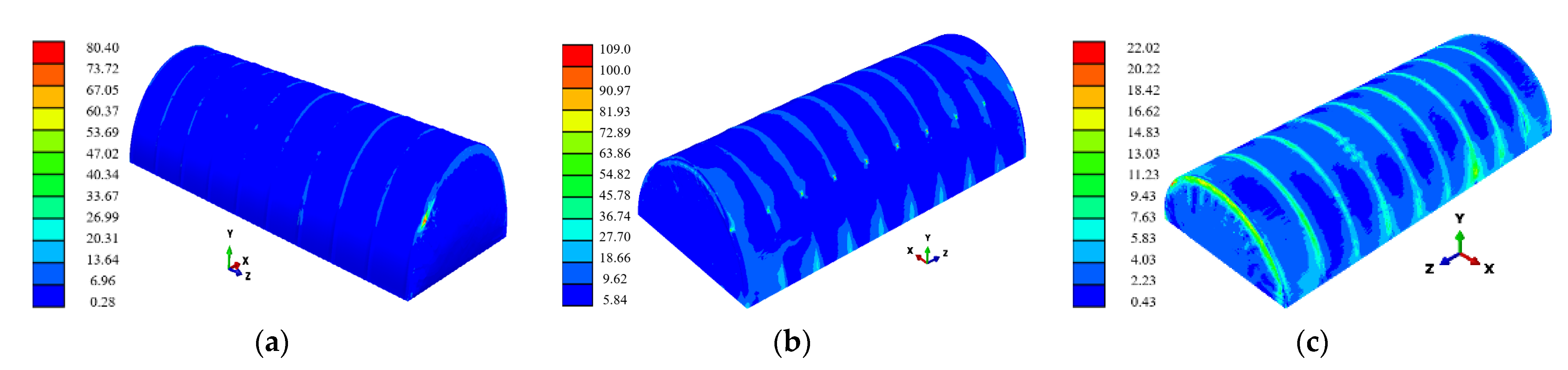
Figure 8.
The stress of the tarpaulin in case 1, case 2, and case 3. (a) 0° wind direction angle; (b) 45° wind direction angle; (c) 90° wind direction angle. The data unit is MPa.
Figure 8.
The stress of the tarpaulin in case 1, case 2, and case 3. (a) 0° wind direction angle; (b) 45° wind direction angle; (c) 90° wind direction angle. The data unit is MPa.
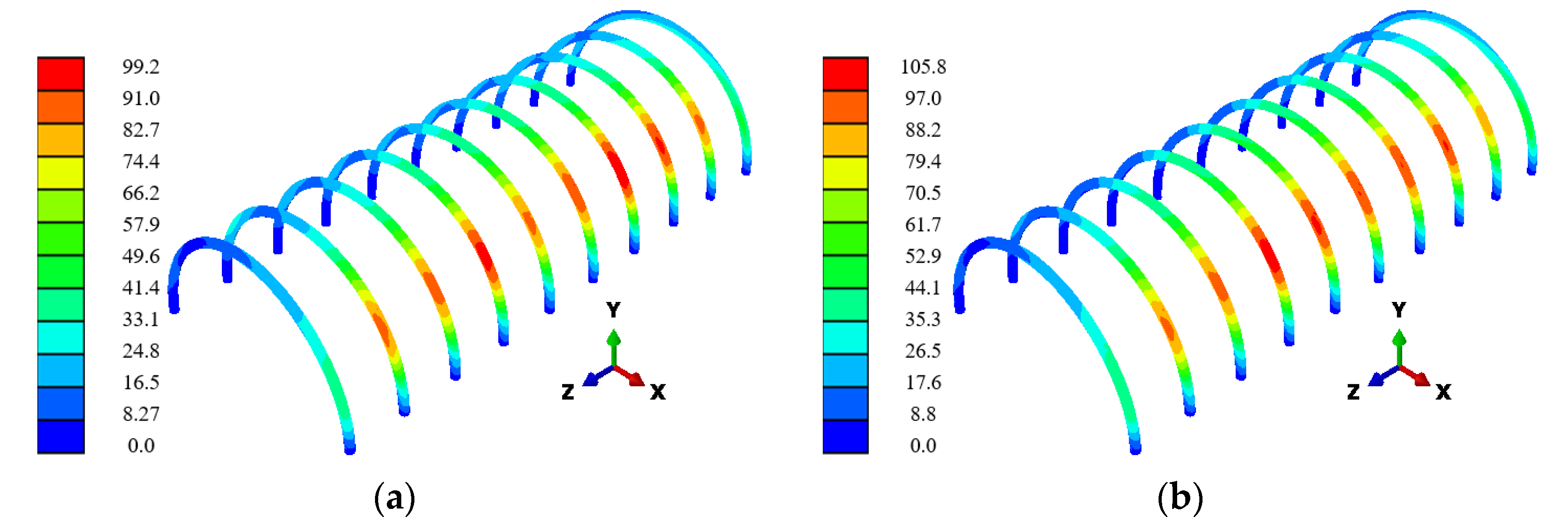
Figure 9.
The stress of the air ribs in case 1, case 2, and case 3. (a) 0° wind direction angle; (b) 45° wind direction angle; (c) 90° wind direction angle. The data unit is MPa.
Figure 9.
The stress of the air ribs in case 1, case 2, and case 3. (a) 0° wind direction angle; (b) 45° wind direction angle; (c) 90° wind direction angle. The data unit is MPa.
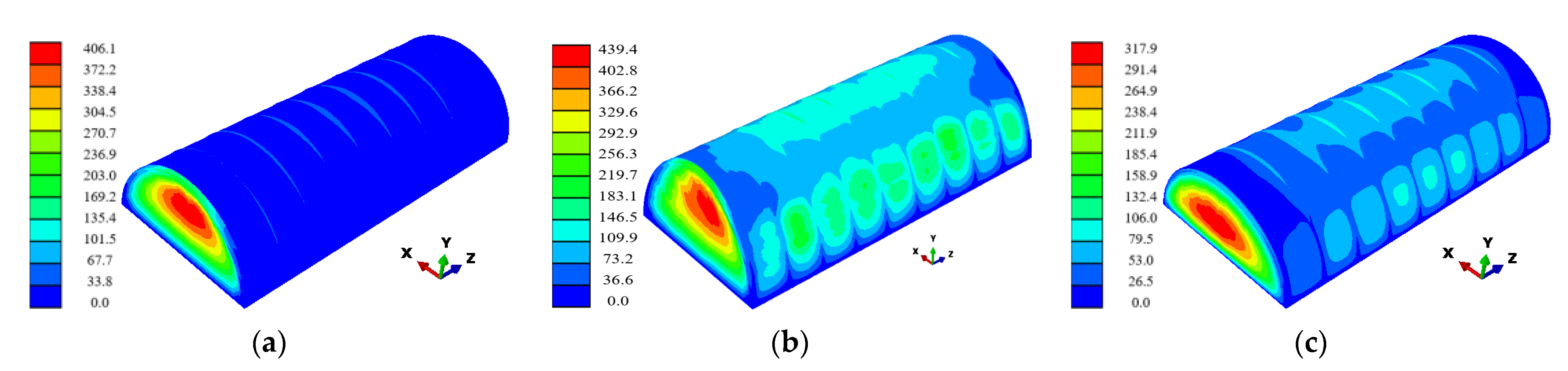
Figure 10.
The displacement of the tarpaulin in case 1, case 2, and case 3. (a) 0° wind direction angle; (b) 45° wind direction angle; (c) 90° wind direction angle. The data unit is mm.
Figure 10.
The displacement of the tarpaulin in case 1, case 2, and case 3. (a) 0° wind direction angle; (b) 45° wind direction angle; (c) 90° wind direction angle. The data unit is mm.
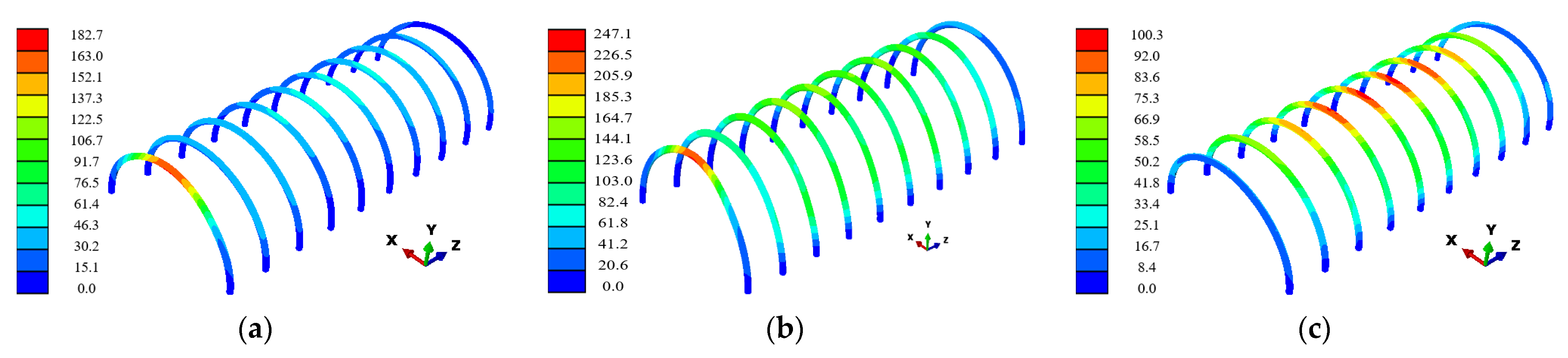
Figure 11.
The overall displacement of the air ribs in case 1, case 2, and case 3. (a) 0° wind direction angle; (b) 45° wind direction angle; (c) 90° wind direction angle. The data unit is mm.
Figure 11.
The overall displacement of the air ribs in case 1, case 2, and case 3. (a) 0° wind direction angle; (b) 45° wind direction angle; (c) 90° wind direction angle. The data unit is mm.
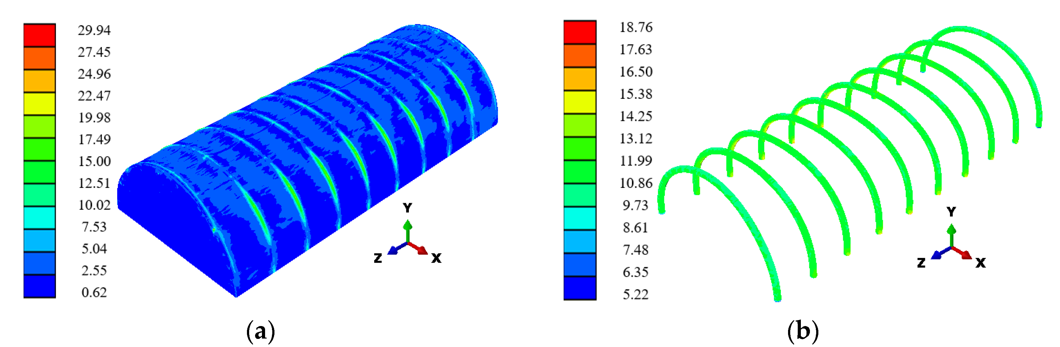
Figure 12.
The stress of the tarpaulin and air ribs in case 4. (a) Tarpaulin. (b) Air ribs. The data unit is MPa.
Figure 12.
The stress of the tarpaulin and air ribs in case 4. (a) Tarpaulin. (b) Air ribs. The data unit is MPa.
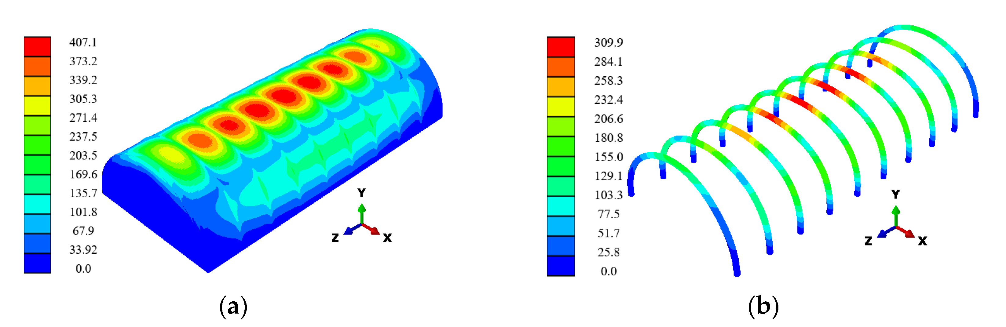
Figure 13.
The displacement of the tarpaulin and air ribs in case 4. (a) Tarpaulin. (b) Air ribs. The data unit is mm.
Figure 13.
The displacement of the tarpaulin and air ribs in case 4. (a) Tarpaulin. (b) Air ribs. The data unit is mm.
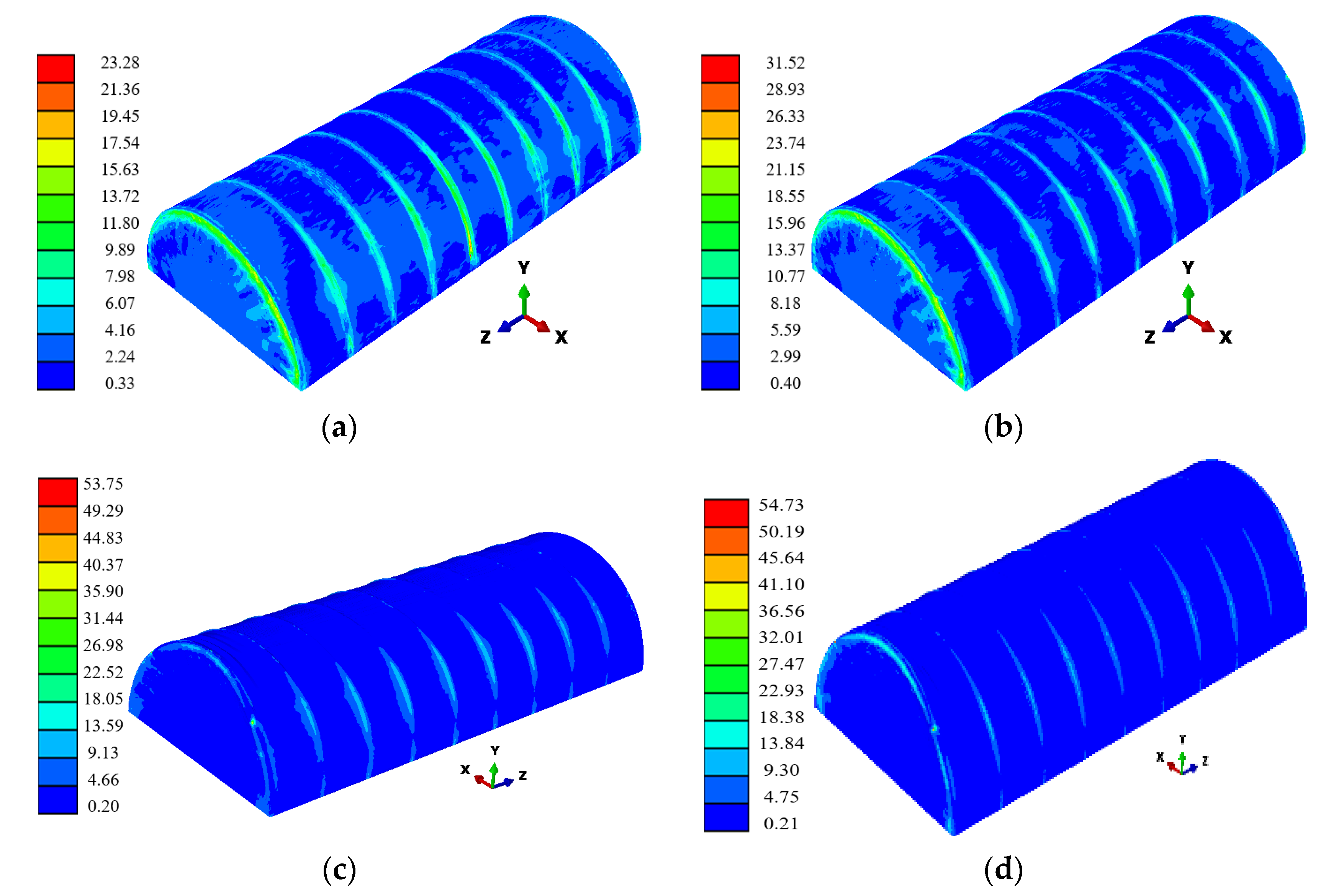
Figure 14.
The stress of the tarpaulin in case 5, case 6, case 7, and case 8. (a) Case 5. (b) Case 6. (c) Case 7. (d) Case 8. The data unit is MPa.
Figure 14.
The stress of the tarpaulin in case 5, case 6, case 7, and case 8. (a) Case 5. (b) Case 6. (c) Case 7. (d) Case 8. The data unit is MPa.
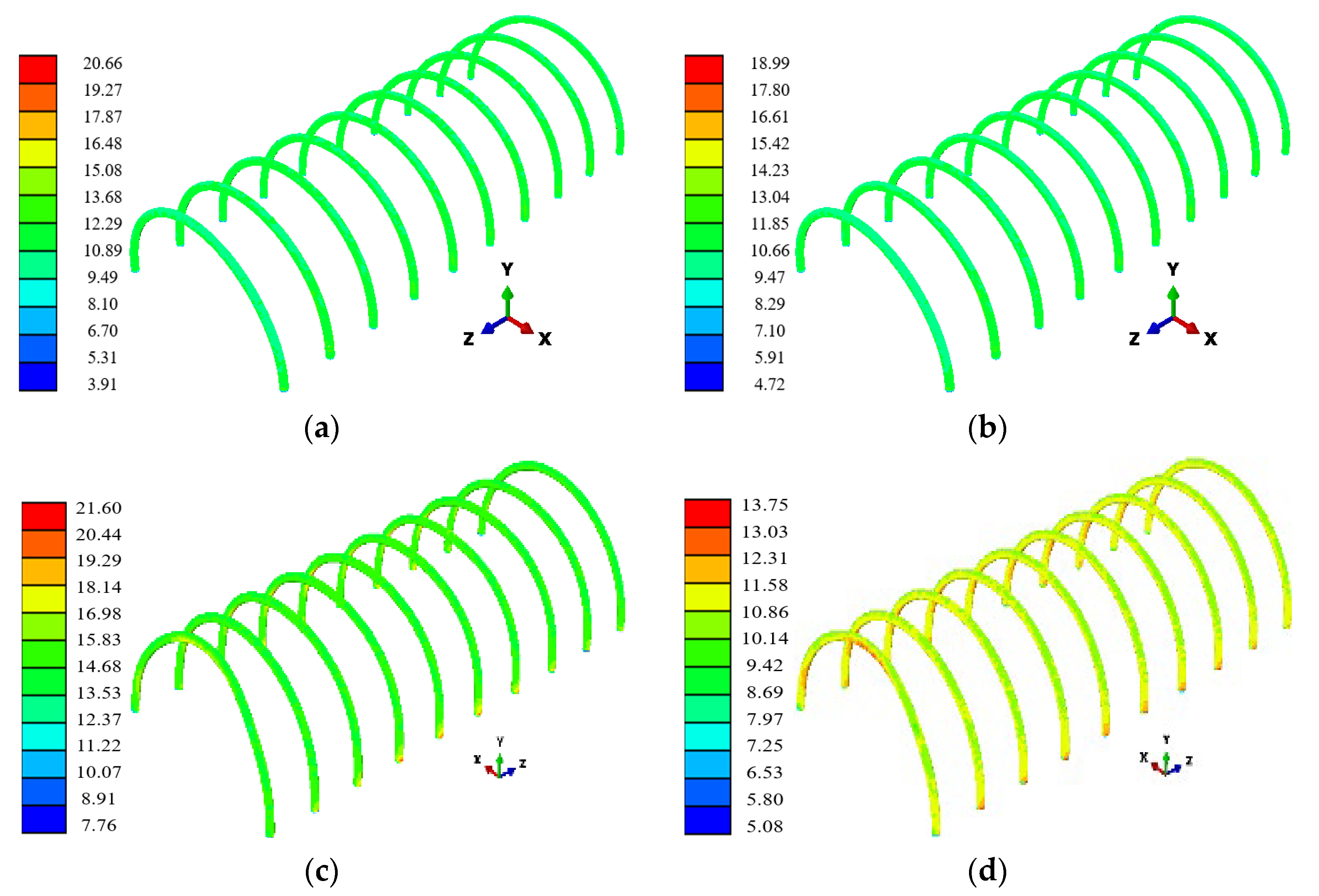
Figure 15.
The stress of the air ribs in case 5, case 6, case 7, and case 8. (a) Case 5. (b) Case 6. (c) Case 7. (d) Case 8. The data unit is MPa.
Figure 15.
The stress of the air ribs in case 5, case 6, case 7, and case 8. (a) Case 5. (b) Case 6. (c) Case 7. (d) Case 8. The data unit is MPa.
Figure 16.
The displacement of the tarpaulin in case 5, case 6, case 7, and case 8. (a) Case 5. (b) Case 6. (c) Case 7. (d) Case 8. The data unit is mm.
Figure 16.
The displacement of the tarpaulin in case 5, case 6, case 7, and case 8. (a) Case 5. (b) Case 6. (c) Case 7. (d) Case 8. The data unit is mm.
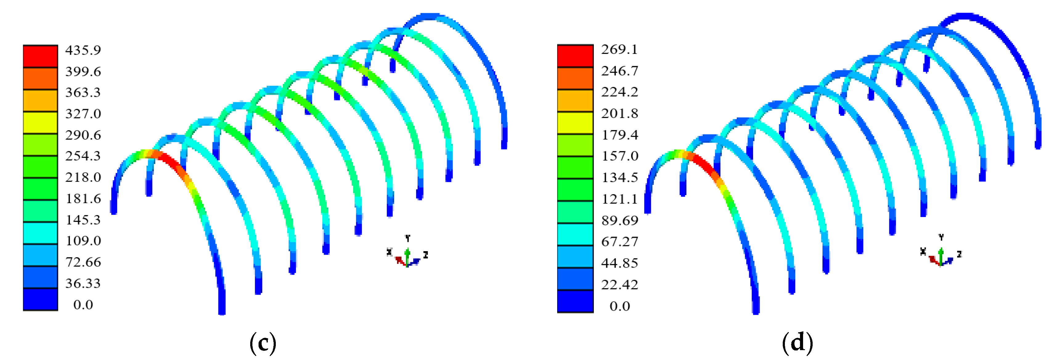
Figure 17.
The displacement of the air ribs in in case 5, case 6, case 7, and case 8. (a) Case 5. (b) Case 6. (c) Case 7. (d) Case 8. The data unit is mm.
Figure 17.
The displacement of the air ribs in in case 5, case 6, case 7, and case 8. (a) Case 5. (b) Case 6. (c) Case 7. (d) Case 8. The data unit is mm.
Table 1.
The property parameters of membrane structure material.
Table 1.
The property parameters of membrane structure material.
| Name | Material | Thickness (mm) | Density (g/cm3) | Elasticity Modulus (GPa) | Poisson’s Ratio | Breaking Strength (MPa) |
|---|
| tarpaulins | polyester filament Oxford cloth | 0.27 | 1.000 | 0.940 | 0.35 | 178.33 |
| air rib | high-strength fiber | 2.60 | 1.069 | 0.470 | 0.32 | 119.47 |
Table 2.
The shape coefficient of wind load.
Table 2.
The shape coefficient of wind load.
| Location | Stoss Side | Lee Side | Side | Top |
|---|
| shape factor | +0.6 | −0.5 | −0.7 | −0.8 |
Table 3.
The load cases of air-ribbed membrane structure.
Table 3.
The load cases of air-ribbed membrane structure.
| Name of Working Condition | Operating Condition Number | Combination of Loads |
|---|
| 0° angle wind load | case 1 | 1.3 * + 1.5 * |
| 45° angle wind load | case 2 | 1.3 * + 1.5 * |
| 90° angle wind load | case 3 | 1.3 * + 1.5 * |
| snow load | case 4 | 1.3 * + 1.5 * |
| wind and snow load (90° angle wind load; the angle of wind rope is 45°) | case 5 | 1.3 * + 1.5 * + 1.5 * 0.7 * |
| wind and snow load (90° angle wind load; the angle of wind rope is 30°) | case 6 | 1.3 * + 1.5 * + 1.5 * 0.7 * |
| wind and snow load (0° angle wind load; the angle of wind rope is 45°) | case 7 | 1.3 * + 1.5 * + 1.5 * 0.7 * |
| wind and snow load (0° angle wind load; the angle of wind rope is 30°) | case 8 | 1.3 * + 1.5 * + 1.5 * 0.7 * |
Table 4.
The stress of the tarpaulin and the air ribs in case 3, case 4 and case 5.
Table 4.
The stress of the tarpaulin and the air ribs in case 3, case 4 and case 5.
| Working Condition | Stress of Tarpaulin (MPa) | Stress of Air Ribs (MPa) |
|---|
| case 3 | 22.02 | 17.97 |
| case 4 | 29.94 | 18.76 |
| case 5 | 23.28 | 20.66 |
Table 5.
The displacement of the tarpaulin and air ribs in case 3, case 4, and case 5.
Table 5.
The displacement of the tarpaulin and air ribs in case 3, case 4, and case 5.
| Working Condition | Displacement of Tarpaulin (MPa) | Displacement of Air Ribs (MPa) |
|---|
| case 3 | 317.9 | 100.3 |
| case 4 | 402.1 | 309.9 |
| case 5 | 325.9 | 99.2 |
Table 6.
The maximum and average stress of the tarpaulin in case 4 and case 5.
Table 6.
The maximum and average stress of the tarpaulin in case 4 and case 5.
| Working Condition | Maximum Stress (MPa) | Average Stress of Stress Band (MPa) | Stress between End Face and Air Frame (MPa) |
|---|
| case 5 | 23.28 | 11.80 | 2.24 |
| case 6 | 31.52 | 15.96 | 2.99 |
| case 7 | 53.75 | 17.05 | 3.88 |
| case 8 | 54.73 | 13.84 | 3.85 |
Table 7.
The maximum and average stress of the air ribs in case 5, case 6, case 7, and case 8.
Table 7.
The maximum and average stress of the air ribs in case 5, case 6, case 7, and case 8.
| Working Condition | Maximum Stress | Average Stress |
|---|
| case 5 | 20.66 | 12.29 |
| case 6 | 18.99 | 11.85 |
| case 7 | 21.60 | 13.53 |
| case 8 | 13.75 | 9.42 |


