

Experimental Investigation of the Desalination Process for Direct Contact Membrane Distillation Using Plate and Frame Membrane Module


Abstract
:1. Introduction
2. Materials and Methods
2.1. The Evaluation Index of Membrane Distillation
Permeate Flux
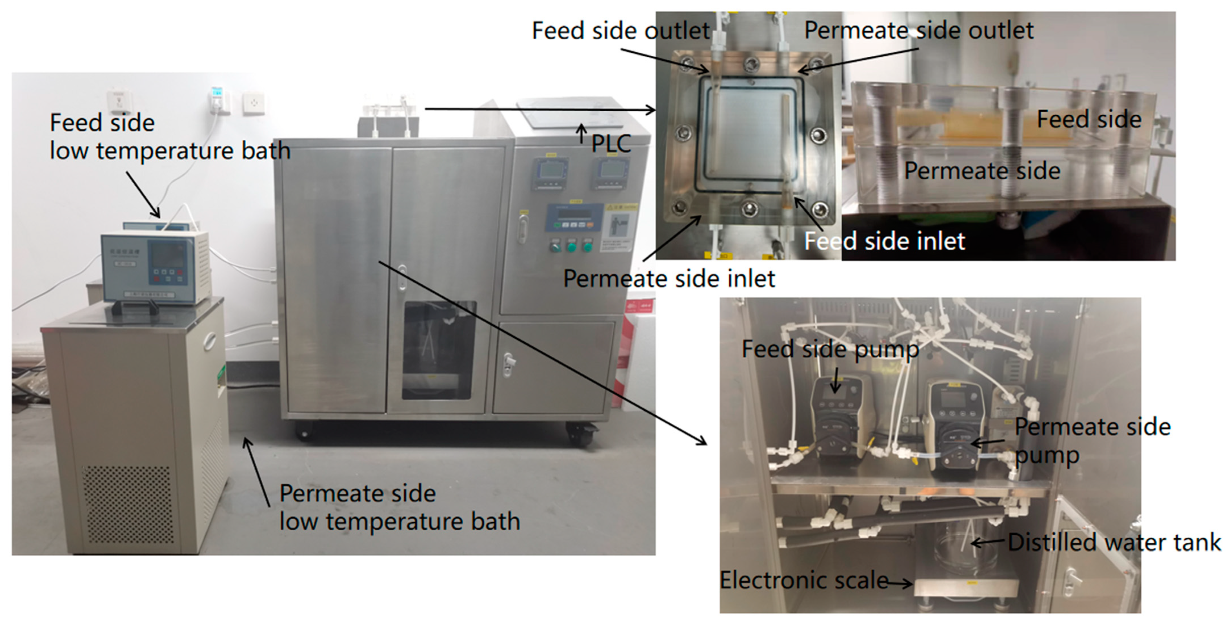
2.2. Experimental Materials and Equipment
- (1)
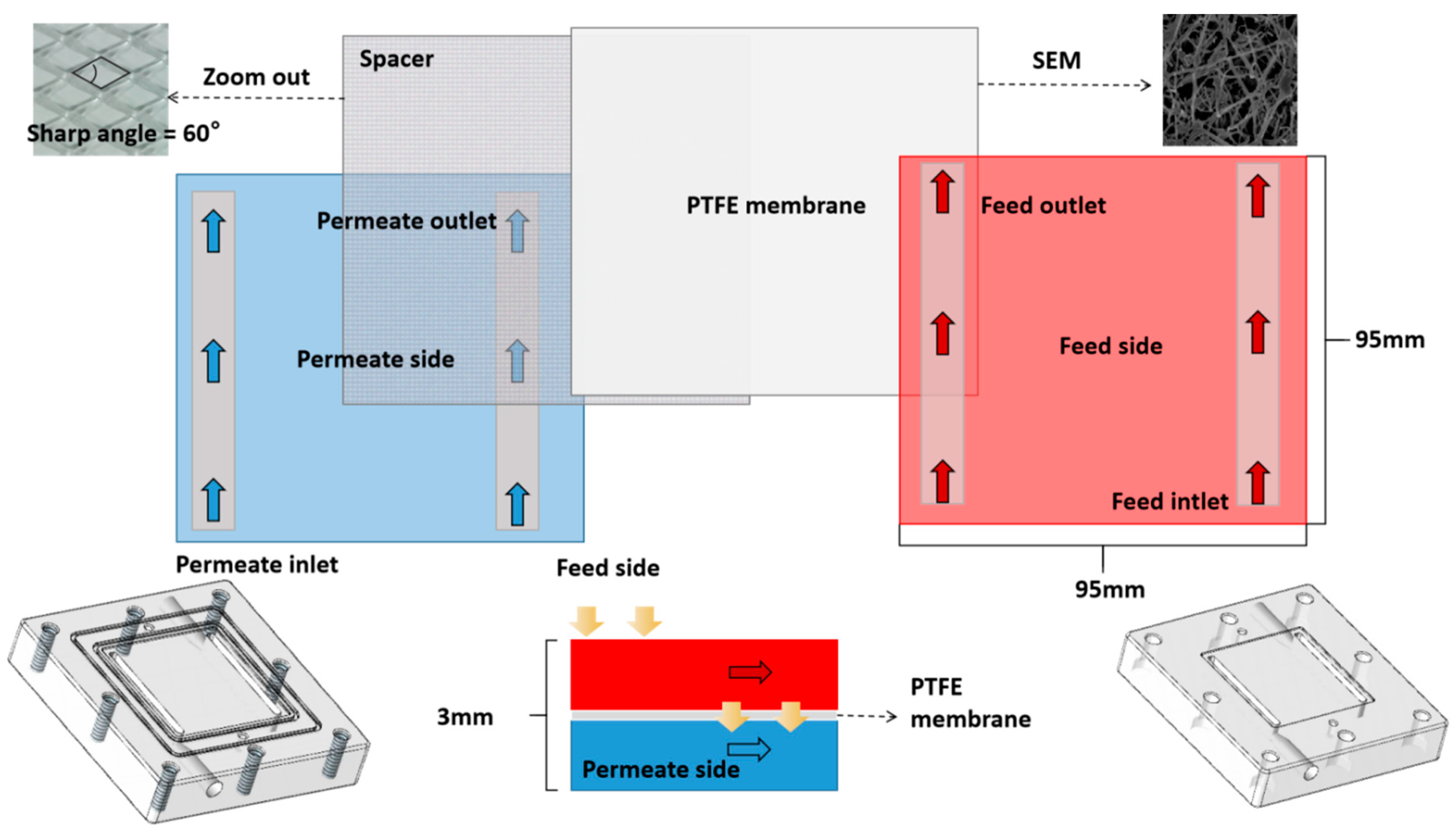
- Membrane module
- (2)
- Feed side (hot-side) pump
- (3)
- Constant Temperature Tank
- (4)
- Electronic scale
- (5)
- Permeate side (cold-side) pump
- (6)
- Temperature and conductivity sensors
3. Results and Discussion
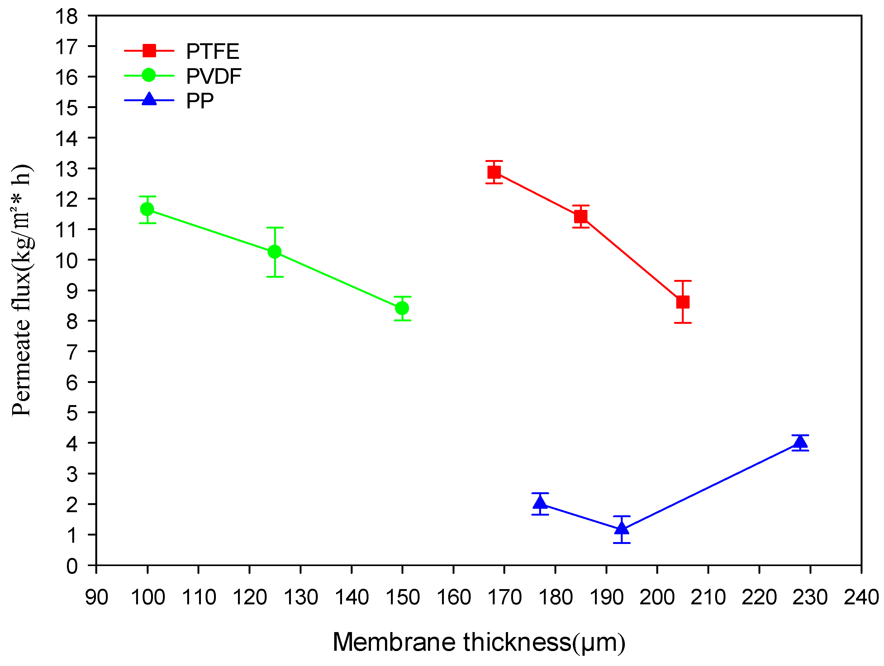
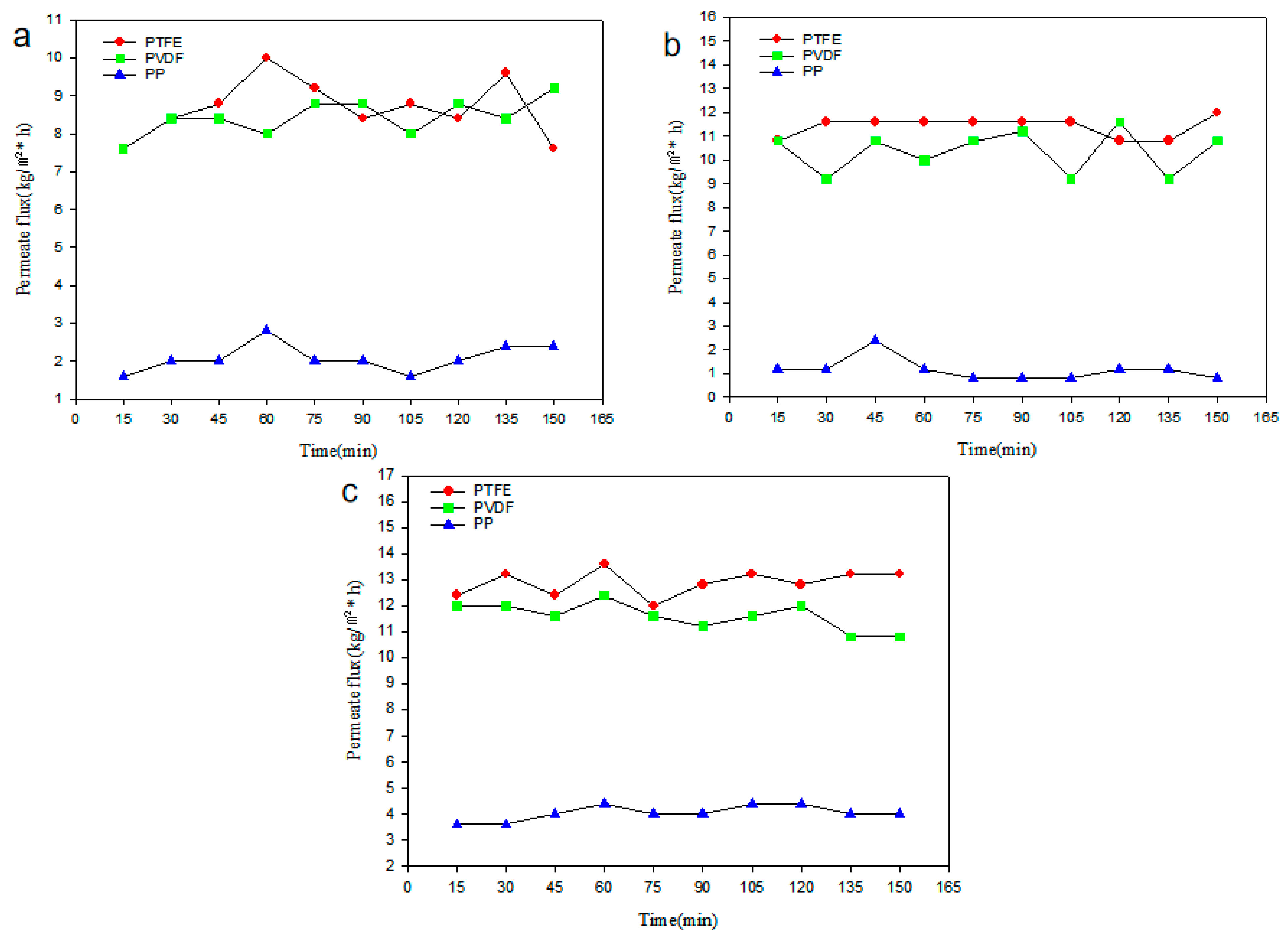
3.1. Effect of Membrane Materials on the Permeate Flux of the DCMD Process
3.2. The Effect of Operational Conditions on the DCMD Process
4. Conclusions
- (1)
- PTFE and PVDF membranes are the best choice of membrane materials for membrane distillation, whereas pp membranes are not recommended. The permeate fluxes of PVDF and PTFE membranes are very close when their pore sizes are 1.0 μm.
- (2)
- Without considering the membrane fouling and scale-up issues caused by long-time desalination processes, the permeate flux of PTFE and PVDF membrane increases with the increase in the pore size. In contrast, the permeate flux of pp membranes does not vary significantly with pore size. Additionally, in this study, Jpvdf1.0 = 1.136Jpvdf0.45 = 1.386Jpvdf0.22, Jptfe1.0 = 1.267Jptfe0.45 = 1.377Jptfe0.22.
- (3)
- Under operating conditions of constant inlet flow on the hot and cold sides, increasing the hot-side temperature and decreasing the cold-side temperature facilitates the increase in permeate flux in membrane distillation systems. Moreover, the hot-side temperature and cold-side inlet flow rate have a greater influence on improving the permeate flux, and the optimal combination is A3B1C3 in this experiment.
Author Contributions
Funding
Institutional Review Board Statement
Informed Consent Statement
Data Availability Statement
Conflicts of Interest
References
- Chen, L.; Wu, B. Research Progress in Computational Fluid Dynamics Simulations of Membrane Distillation Processes: A Review. Membranes 2021, 11, 513. [Google Scholar] [CrossRef] [PubMed]
- Drioli, E.; Ali, A.; Macedonio, F. Membrane distillation: Recent developments and perspectives. Desalination 2015, 356, 56–84. [Google Scholar] [CrossRef]
- Khan, A.; Yadav, S.; Ibrar, I.; Al Juboori, R.A.; Razzak, S.A.; Deka, P.; Subbiah, S.; Shah, S. Fouling and Performance Investigation of Membrane Distillation at Elevated Recoveries for Seawater Desalination and Wastewater Reclamation. Membranes 2022, 12, 951. [Google Scholar] [CrossRef] [PubMed]
- Khayet, M. Membranes and theoretical modeling of membrane distillation: A review. Adv. Colloid Interface Sci. 2011, 164, 56–88. [Google Scholar] [CrossRef] [PubMed]
- Eleiwi, F.; Ghaffour, N.; Alsaadi, A.S.; Francis, L.; Laleg-Kirati, T.M. Dynamic modeling and experimental validation for direct contact membrane distillation (DCMD) process. Desalination 2016, 384, 1–11. [Google Scholar] [CrossRef]
- Li, Z.; Peng, Y.; Dong, Y.; Fan, H.; Chen, P.; Qiu, L.; Jiang, Q. Effects of thermal efficiency in DCMD and the preparation of membranes with low thermal conductivity. Appl. Surf. Sci. 2014, 317, 338–349. [Google Scholar] [CrossRef]
- Yazgan-Birgi, P.; Ali, M.I.H.; Arafat, H.A. Comparative performance assessment of flat sheet and hollow fiber DCMD processes using CFD modeling. Sep. Purif. Technol. 2019, 212, 709–722. [Google Scholar] [CrossRef]
- Abu-Zeid MA, E.R.; Zhang, Y.; Dong, H.; Zhang, L.; Chen, H.L.; Hou, L. A comprehensive review of vacuum membrane distillation technique. Desalination 2015, 356, 1–14. [Google Scholar] [CrossRef]
- Andrés-Mañas, J.A.; Ruiz-Aguirre, A.; Acién, F.G.; Zaragoza, G. Assessment of a pilot system for seawater desalination based on vacuum multi-effect membrane distillation with enhanced heat recovery. Desalination 2018, 443, 110–121. [Google Scholar] [CrossRef]
- Andrjesdóttir, Ó.; Ong, C.L.; Nabavi, M.; Paredes, S.; Khalil, A.S.G.; Michel, B.; Poulikakos, D. An experimentally optimized model for heat and mass transfer in direct contact membrane distillation. Int. J. Heat Mass Transf. 2013, 66, 855–867. [Google Scholar] [CrossRef]
- Camacho, L.M.; Dumée, L.; Zhang, J.; Li, J.D.; Duke, M.; Gomez, J.; Gray, S. Advances in membrane distillation for water desalination and purification applications. Water 2013, 5, 94–196. [Google Scholar] [CrossRef]
- Elmarghany, M.R.; El-Shazly, A.H.; Salem, M.S.; Sabry, M.N.; Nady, N. Thermal analysis evaluation of direct contact membrane distillation system. Case Stud. Therm. Eng. 2019, 13, 100377. [Google Scholar] [CrossRef]
- Ashoor, B.B.; Mansour, S.; Giwa, A.; Dufour, V.; Hasan, S.W. Principles and applications of direct contact membrane distillation (DCMD): A comprehensive review. Desalination 2016, 398, 222–246. [Google Scholar] [CrossRef]
- Ge, J.; Peng, Y.; Li, Z.; Chen, P.; Wang, S. Membrane fouling and wetting in a DCMD process for RO brine concentration. Desalination 2014, 344, 97–107. [Google Scholar] [CrossRef]
- Manawi, Y.M.; Khraisheh, M.; Fard, A.K.; Benyahia, F.; Adham, S. Effect of operational parameters on distillate flux in direct contact membrane distillation (DCMD): Comparison between experimental and model predicted performance. Desalination 2014, 336, 110–120. [Google Scholar] [CrossRef]
- Francis, L.; Ghaffour, N.E.; Alsaadi, A.S.; Nunes, S.P.; Amy, G.L. Performance evaluation of the DCMD desalination process under bench scale and large scale module operating conditions. J. Membr. Sci. 2014, 455, 103–112. [Google Scholar] [CrossRef]
- He, K.; Hwang, H.J.; Woo, M.W.; Moon, I.S. Production of drinking water from saline water by direct contact membrane distillation (DCMD). J. Ind. Eng. Chem. 2011, 17, 41–48. [Google Scholar] [CrossRef]
- Baig, U.; Faizan, M.; Waheed, A. A review on super-wettable porous membranes and materials based on bio-polymeric chitosan for oil-water separation. Adv. Colloid Interface Sci. 2022, 303, 102635. [Google Scholar] [CrossRef]
- Baig, U.; Waheed, A.; Dastageer, M.A. Facile fabrication of silicon carbide decorated ceramic membrane, engineered with selective surface wettability for highly efficient separation of oil-in-water emulsions. J. Environ. Chem. Eng. 2023, 11, 109357. [Google Scholar] [CrossRef]
- Okati, V.; Moghadam, A.J.; Farzaneh-Gord, M.; Moein-Jahromi, M. Thermo-economical and environmental analyses of a Direct Contact Membrane Distillation (DCMD) performance. J. Clean. Prod. 2022, 340, 130613. [Google Scholar] [CrossRef]
- Criscuoli, A. Experimental investigation of the thermal performance of new flat membrane module designs for membrane distillation. Int. Commun. Heat Mass Transf. 2019, 103, 83–89. [Google Scholar] [CrossRef]
- Okabe, K. Experimental simulation of membrane module performance in direct contact membrane distillation. Int. J. Heat Mass Transf. 2021, 172, 121188. [Google Scholar] [CrossRef]
- Deshpande, J.; Nithyanandam, K.; Pitchumani, R. Analysis and design of direct contact membrane distillation. J. Membr. Sci. 2017, 523, 301–316. [Google Scholar] [CrossRef]
- Boubakri, A.; Hafiane, A.; Bouguecha, S.A.T. Direct contact membrane distillation: Capability to desalt raw water. Arab. J. Chem. 2017, 10, S3475–S3481. [Google Scholar] [CrossRef]
- Singh, D.; Sirkar, K.K. Desalination of brine and produced water by direct contact membrane distillation at high temperatures and pressures. J. Membr. Sci. 2012, 389, 380–388. [Google Scholar] [CrossRef]
- Ho, C.D.; Huang, C.H.; Tsai, F.C.; Chen, W.T. Performance improvement on distillate flux of countercurrent-flow direct contact membrane distillation systems. Desalination 2014, 338, 26–32. [Google Scholar] [CrossRef]
- Deshmukh, A.; Elimelech, M. Understanding the impact of membrane properties and transport phenomena on the energetic performance of membrane distillation desalination. J. Membr. Sci. 2017, 539, 458–474. [Google Scholar] [CrossRef]
- Swaminathan, J.; Chung, H.W.; Warsinger, D.M. Simple method for balancing direct contact membrane distillation. Desalination 2016, 383, 53–59. [Google Scholar] [CrossRef]
- Soukane, S.; Naceur, M.W.; Francis, L.; Alsaadi, A.; Ghaffour, N. Effect of feed flow pattern on the distribution of permeate fluxes in desalination by direct contact membrane distillation. Desalination 2017, 418, 43–59. [Google Scholar] [CrossRef]
- Lee, J.G.; Kim, W.S.; Choi, J.S.; Ghaffour, N.; Kim, Y.D. A novel multi-stage direct contact membrane distillation module: Design, experimental and theoretical approaches. Water Res. 2016, 107, 47–56. [Google Scholar] [CrossRef]
- Bouchrit, R.; Boubakri, A.; Hafiane, A.; Bouguecha, S.A.T. Direct contact membrane distillation: Capability to treat hyper-saline solution. Desalination 2015, 376, 117–129. [Google Scholar] [CrossRef]
- Bahmanyar, A.; Asghari, M.; Khoobi, N. Numerical simulation and theoretical study on simultaneously effects of operating parameters in direct contact membrane distillation. Chem. Eng. Process. Process Intensif. 2012, 61, 42–50. [Google Scholar] [CrossRef]
- Liu, Y.J.; Han, J.T.; Wang, Y.S.; Tien-Chien, J. Experimental study on saline solution by direct contact membrane distillation. CIESC J. 2018, 69, 246–251. [Google Scholar]
- Katsandri, A. A theoretical analysis of a spacer filled flat plate membrane distillation modules using CFD: Part II: Temperature polarisation analysis. Desalination 2017, 408, 166–180. [Google Scholar] [CrossRef]
- Khayet, M.; Matsuura, T.; Mengual, J.I.; Qtaishat, M. Design of novel direct contact membrane distillation membranes. Desalination 2006, 192, 105–111. [Google Scholar] [CrossRef]
- Khalifa, A.; Ahmad, H.; Antar, M.; Laoui, T.; Khayet, M. Experimental and theoretical investigations on water desalination using direct contact membrane distillation. Desalination 2017, 404, 22–34. [Google Scholar] [CrossRef]
- El-Bourawi, M.S.; Ding, Z.; Ma, R.; Khayet, M. A framework for better understanding membrane distillation separation process. J. Membr. Sci. 2006, 285, 4–29. [Google Scholar] [CrossRef]
- Zhang, J.; Dow, N.; Duke, M.; Ostarcevic, E.; Li, J.-D.; Gray, S. Identification of material and physical features of membrane distillation membranes for high performance desalination. J. Membr. Sci. 2010, 349, 295–303. [Google Scholar] [CrossRef]
- Shirazi MM, A.; Kargari, A.; Tabatabaei, M. Evaluation of commercial PTFE membranes in desalination by direct contact membrane distillation. Chem. Eng. Process. Process Intensif. 2014, 76, 16–25. [Google Scholar] [CrossRef]
- Boubakri, A.; Hafiane, A.; Bouguecha, S.A.T. Application of response surface methodology for modeling and optimization of membrane distillation desalination process. J. Ind. Eng. Chem. 2014, 20, 3163–3169. [Google Scholar] [CrossRef]
- Gunko, S.; Verbych, S.; Bryk, M.; Hilal, N. Concentration of apple juice using direct contact membrane distillation. Desalination 2006, 190, 117–124. [Google Scholar] [CrossRef]
- Heloisa, R.; Francisco, M.R.A.; Cintia, M.; Ramlow, H.; Machado, R.A.F.; Marangoni, C. Direct contact membrane distillation for textile wastewater treatment: A state of the art review. Water Sci. Technol. 2017, 76, 2565–2579. [Google Scholar]
- Ni, W.; Li, Y.; Zhao, J.; Zhang, G.; Du, X.; Dong, Y. Simulation study on direct contact membrane distillation modules for high-concentration NaCl solution. Membranes 2020, 10, 179. [Google Scholar] [CrossRef] [PubMed]
- Ali, E. Novel structures of direct contact membrane distillation for brackish water desalination using distributed feed flow. Desalination 2022, 540, 116000. [Google Scholar] [CrossRef]
- Chen, T.C.; Ho, C.D.; Yeh, H.M. Theoretical modeling and experimental analysis of direct contact membrane distillation. J. Membr. Sci. 2009, 330, 279–287. [Google Scholar] [CrossRef]
- Banat, F.A.; Simandl, J. Desalination by membrane distillation: A parametric study. Sep. Sci. Technol. 1998, 33, 201–226. [Google Scholar] [CrossRef]
- Manawi, Y.M.; Khraisheh, M.A.M.M.; Fard, A.K.; Benyahia, F.; Adham, S. A predictive model for the assessment of the temperature polarization effect in direct contact membrane distillation desalination of high salinity feed. Desalination 2014, 341, 38–49. [Google Scholar] [CrossRef]
- Su, M.; Teoh, M.M.; Wang, K.Y.; Su, J.; Chung, T.-S. Effect of inner-layer thermal conductivity on flux enhancement of dual-layer hollow fiber membranes in direct contact membrane distillation. J. Membr. Sci. 2010, 364, 278–289. [Google Scholar] [CrossRef]
- Hayer, H.; Bakhtiari, O.; Mohammadi, T. Simulation of momentum, heat and mass transfer in direct contact membrane distillation: A computational fluid dynamics approach. J. Ind. Eng. Chem. 2015, 21, 1379–1382. [Google Scholar] [CrossRef]
- Venault, A.; Chang, K.Y.; Maggay, I.V.; Chang, Y. Assessment of the DCMD performances of poly (vinylidene difluoride) vapor-induced phase separation membranes with adjusted wettability via formation process parameter manipulation. Desalination 2023, 560, 116682. [Google Scholar] [CrossRef]
- Yang, G.; Ng, D.; Huang, Z.; Zhang, J.; Gray, S.; Xie, Z. Janus hollow fibre membranes with intrusion anchored structure for robust desalination and leachate treatment in direct contact membrane distillation. Desalination 2023, 551, 116423. [Google Scholar] [CrossRef]
- Tian, M.; Yuan, S.; Decaesstecker, F.; Zhu, J.; Volodine, A.; Van der Bruggen, B. One-step fabrication of isotropic poly (vinylidene fluoride) membranes for direct contact membrane distillation (DCMD). Desalination 2020, 477, 114265. [Google Scholar] [CrossRef]
- Zhang, J.; Gray, S.; Li, J. Modelling heat and mass transfers in DCMD using compressible membranes. J. Membr. Sci. 2012, 387–388, 7–16. [Google Scholar] [CrossRef]


| Equipment | Equipment Model | Manufacturers |
|---|---|---|
| Membrane | MFPT-2213 | Hangzhou Cobalt Filter Material Co., Hangzhou China. |
| Membrane Components | Xiamen Guochu Co., Xiamen China. | |
| Pump | YZ-1515X | Lange Constant Flow Pump Co., Baoding China. |
| Constant Temperature Tank | DC-1010 | Xiamen Guochu Co., Xiamen China. |
| Temperature and conductivity sensors | EC-4110 | Suntex Instruments Co., Taiwan China. |
| Electronic scale | XH3180-K | Xinhen Instruments Co., Shanghai China. |
| Thickness (μm) | Pore Size (μm) | Thermal Conductivity (W·m−1·K−1) | Porosity % | Contact Angle (°) [5,17,52] | |
|---|---|---|---|---|---|
| PTFE | 205 | 0.22 | 0.2651 | 53.75 | 140 ± 3 |
| 185 | 0.45 | 0.2651 | 46.77 | 140 ± 3 | |
| 168 | 1 | 0.2651 | 53.12 | 140 ± 3 | |
| PP | 177 | 0.22 | 0.13 | 55.22 | 148.1 |
| 193 | 0.45 | 0.13 | 37.73 | 148.1 | |
| 228 | 1 | 0.13 | 55.89 | 148.1 | |
| PVDF | 150 | 0.22 | 0.22 | 85 | 120 ± 10 |
| 125 | 0.45 | 0.22 | 90 | 120 ± 10 | |
| 100 | 1 | 0.22 | 90 | 120 ± 10 |
| Scenario | Pore Size A (μm) | Material B | |
|---|---|---|---|
| 1 | 0.22 | PTFE | 8.62 |
| 2 | 0.45 | PTFE | 11.42 |
| 3 | 1.0 | PTFE | 12.87 |
| 4 | 0.22 | PVDF | 8.40 |
| 5 | 0.45 | PVDF | 10.25 |
| 6 | 1.0 | PVDF | 11.64 |
| 7 | 0.22 | PP | 2.00 |
| 8 | 0.45 | PP | 1.16 |
| 9 | 1.0 | PP | 4.00 |
| Level | Hot-Side Temperature A (°C) | Hot-Side Inlet Flow Rate B (mL/min) | Cold-Side Inlet Flow Rate C (mL/min) |
|---|---|---|---|
| 1 | 60 | 600 | 600 |
| 2 | 70 | 800 | 800 |
| 3 | 80 | 1000 | 1000 |
| Scenario | Hot-Side Temperature A (°C) | Hot-Side Inlet Flow Rate B (mL/min) | Cold-Side Inlet Flow Rate C (mL/min) | Average Permeate flux/J kg/(m²*h) | Standard Deviation |
|---|---|---|---|---|---|
| 1 | 60 | 600 | 600 | 15.4 | 1.07 |
| 2 | 60 | 800 | 800 | 16.1 | 0.85 |
| 3 | 60 | 1000 | 1000 | 17.4 | 1.39 |
| 4 | 70 | 600 | 800 | 23.8 | 1.17 |
| 5 | 70 | 800 | 1000 | 25.2 | 1.03 |
| 6 | 70 | 1000 | 600 | 23.6 | 1.26 |
| 7 | 80 | 600 | 1000 | 35.8 | 1.15 |
| 8 | 80 | 800 | 600 | 30.8 | 0.97 |
| 9 | 80 | 1000 | 800 | 31.7 | 1.40 |
| yj1 | 48.9 | 75.0 | 69.8 | ΣJ = 219.8 | |
| yj2 | 72.6 | 72.1 | 72.8 | ||
| yj3 | 98.3 | 72.7 | 78.4 | ||
| 16.30 | 25.00 | 23.27 | |||
| 24.20 | 24.03 | 24.27 | |||
| 32.77 | 24.23 | 26.13 | |||
| Rj | 16.47 | 0.77 | 2.86 | ||
| Excellent level | A3 | B1 | C3 | ||
| Primary and secondary factors | A | C | B | ||
| Optimal combination | A3B1C3 | ||||
Disclaimer/Publisher’s Note: The statements, opinions and data contained in all publications are solely those of the individual author(s) and contributor(s) and not of MDPI and/or the editor(s). MDPI and/or the editor(s) disclaim responsibility for any injury to people or property resulting from any ideas, methods, instructions or products referred to in the content. |
© 2023 by the authors. Licensee MDPI, Basel, Switzerland. This article is an open access article distributed under the terms and conditions of the Creative Commons Attribution (CC BY) license (https://creativecommons.org/licenses/by/4.0/).
Share and Cite
Zhou, Y.; Chen, L.; Huang, M.; Hu, W.; Chen, G.; Wu, B. Experimental Investigation of the Desalination Process for Direct Contact Membrane Distillation Using Plate and Frame Membrane Module. Appl. Sci. 2023, 13, 9439. https://doi.org/10.3390/app13169439
Zhou Y, Chen L, Huang M, Hu W, Chen G, Wu B. Experimental Investigation of the Desalination Process for Direct Contact Membrane Distillation Using Plate and Frame Membrane Module. Applied Sciences. 2023; 13(16):9439. https://doi.org/10.3390/app13169439
Chicago/Turabian StyleZhou, Yukang, Long Chen, Mengtao Huang, Weilian Hu, Guicai Chen, and Binxin Wu. 2023. "Experimental Investigation of the Desalination Process for Direct Contact Membrane Distillation Using Plate and Frame Membrane Module" Applied Sciences 13, no. 16: 9439. https://doi.org/10.3390/app13169439
APA StyleZhou, Y., Chen, L., Huang, M., Hu, W., Chen, G., & Wu, B. (2023). Experimental Investigation of the Desalination Process for Direct Contact Membrane Distillation Using Plate and Frame Membrane Module. Applied Sciences, 13(16), 9439. https://doi.org/10.3390/app13169439