

Development and Evaluation of a Tethered Class C3 Hexacopter in Maritime Conditions on the Helipad of a Ferry

 , , , , , , and
Abstract
:1. Introduction
Current Advances in Related Research
2. Architecture of the Tethered Hexacopter System
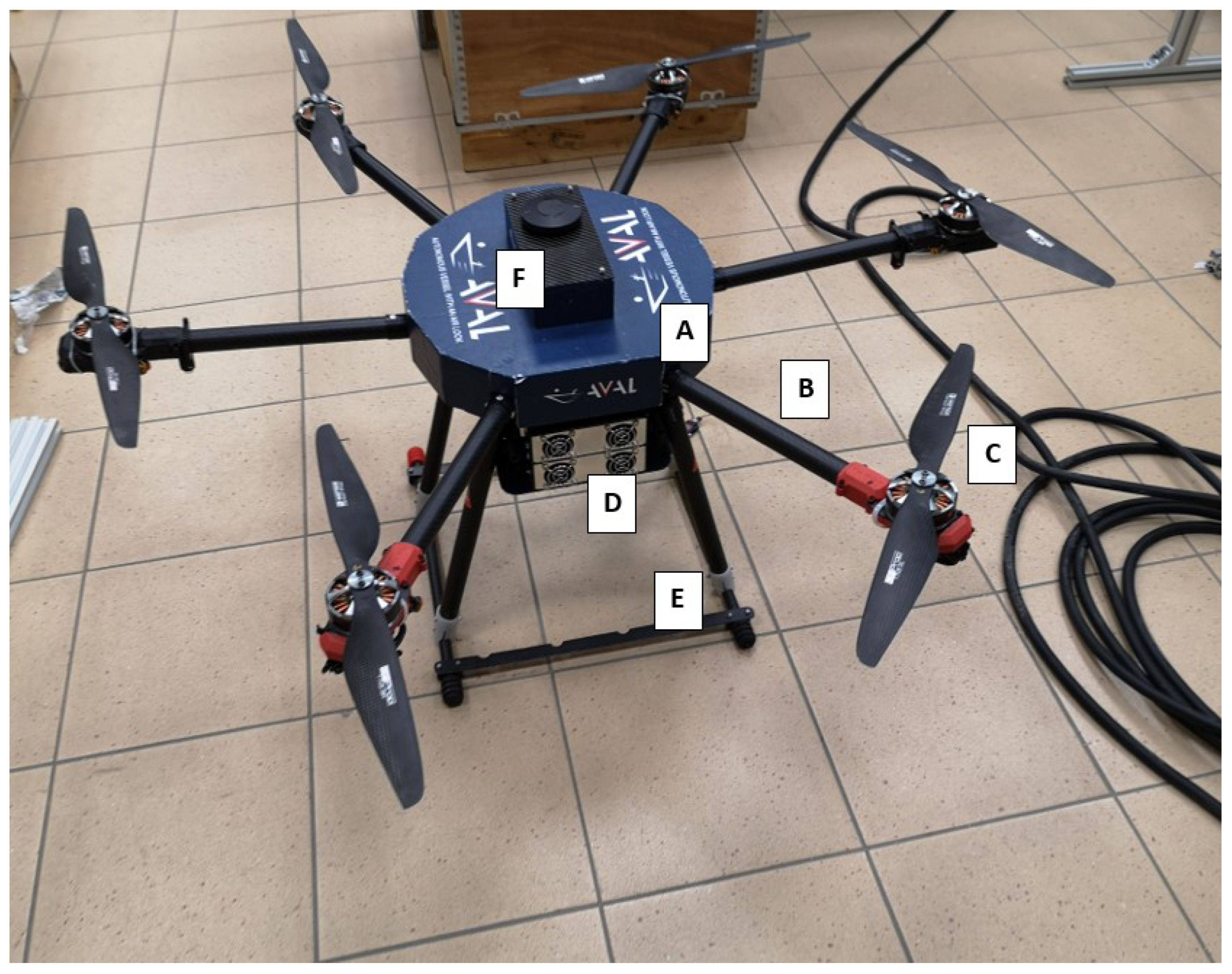
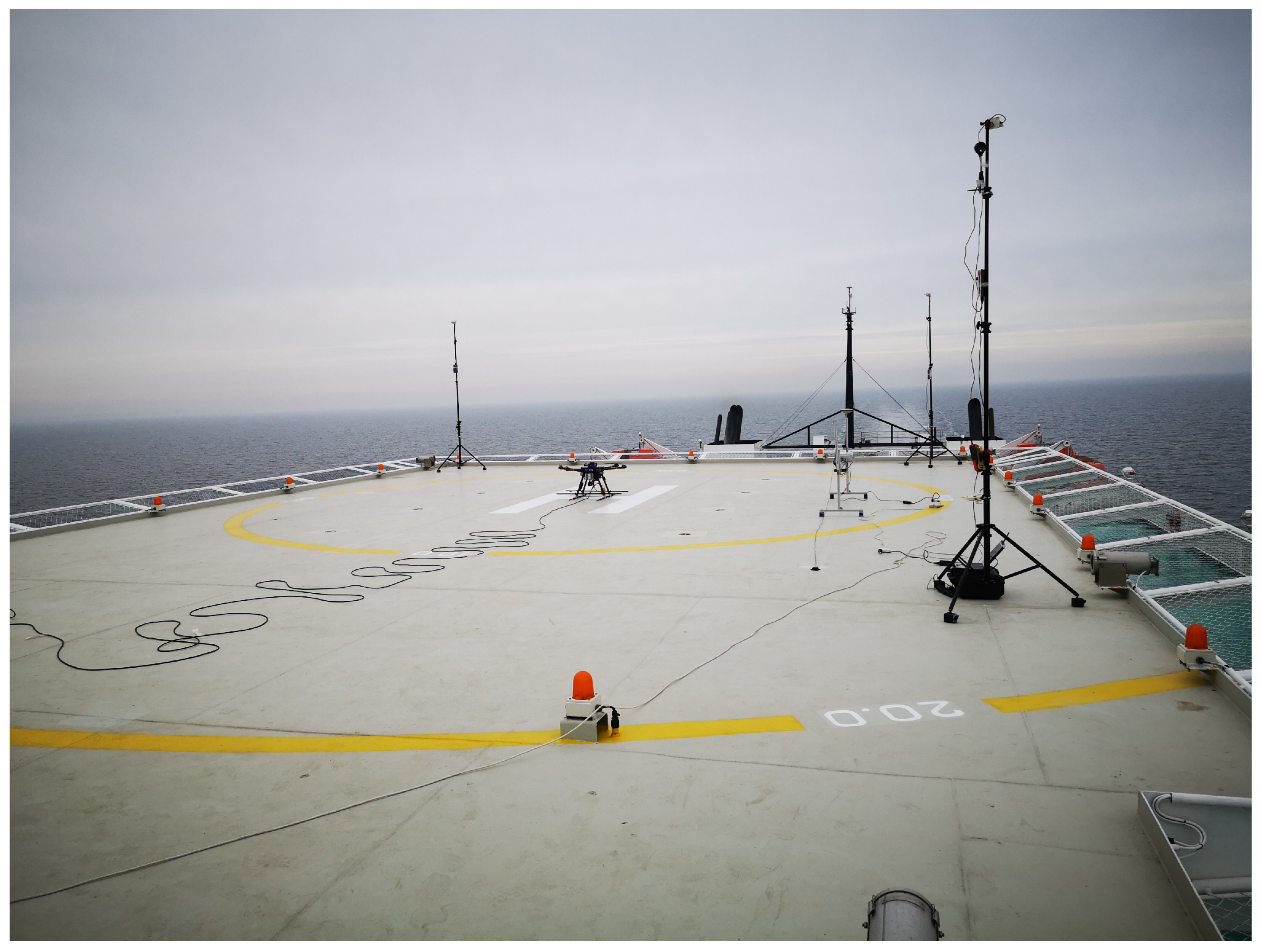
2.1. Tethered Multicopter
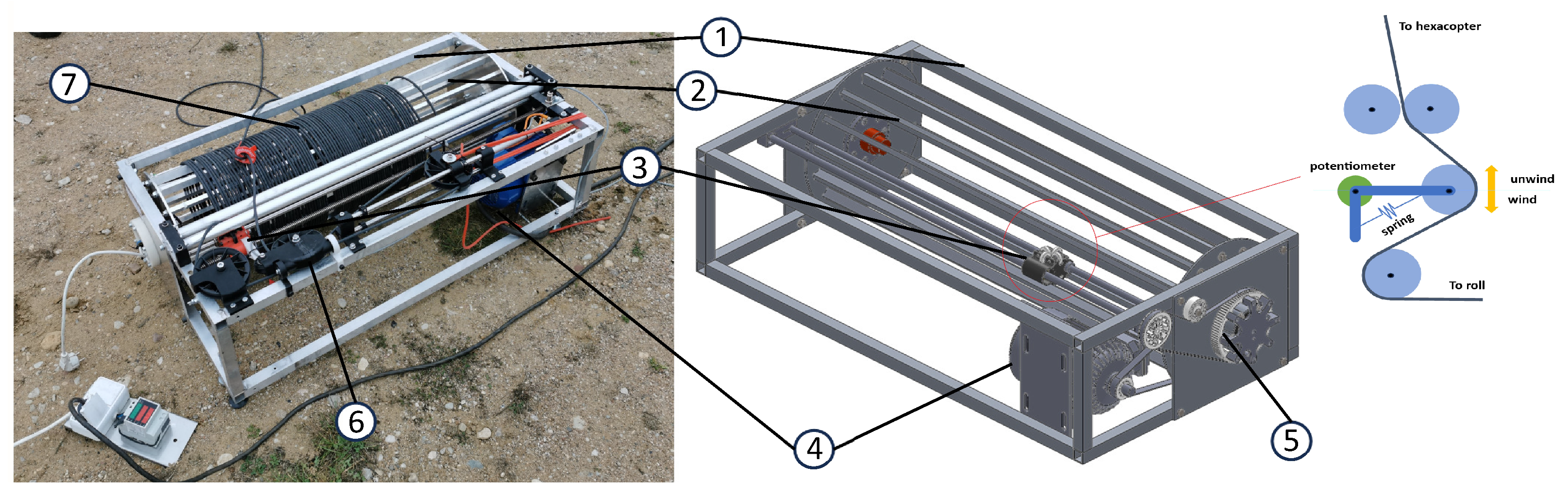
2.2. Tether Unwinder
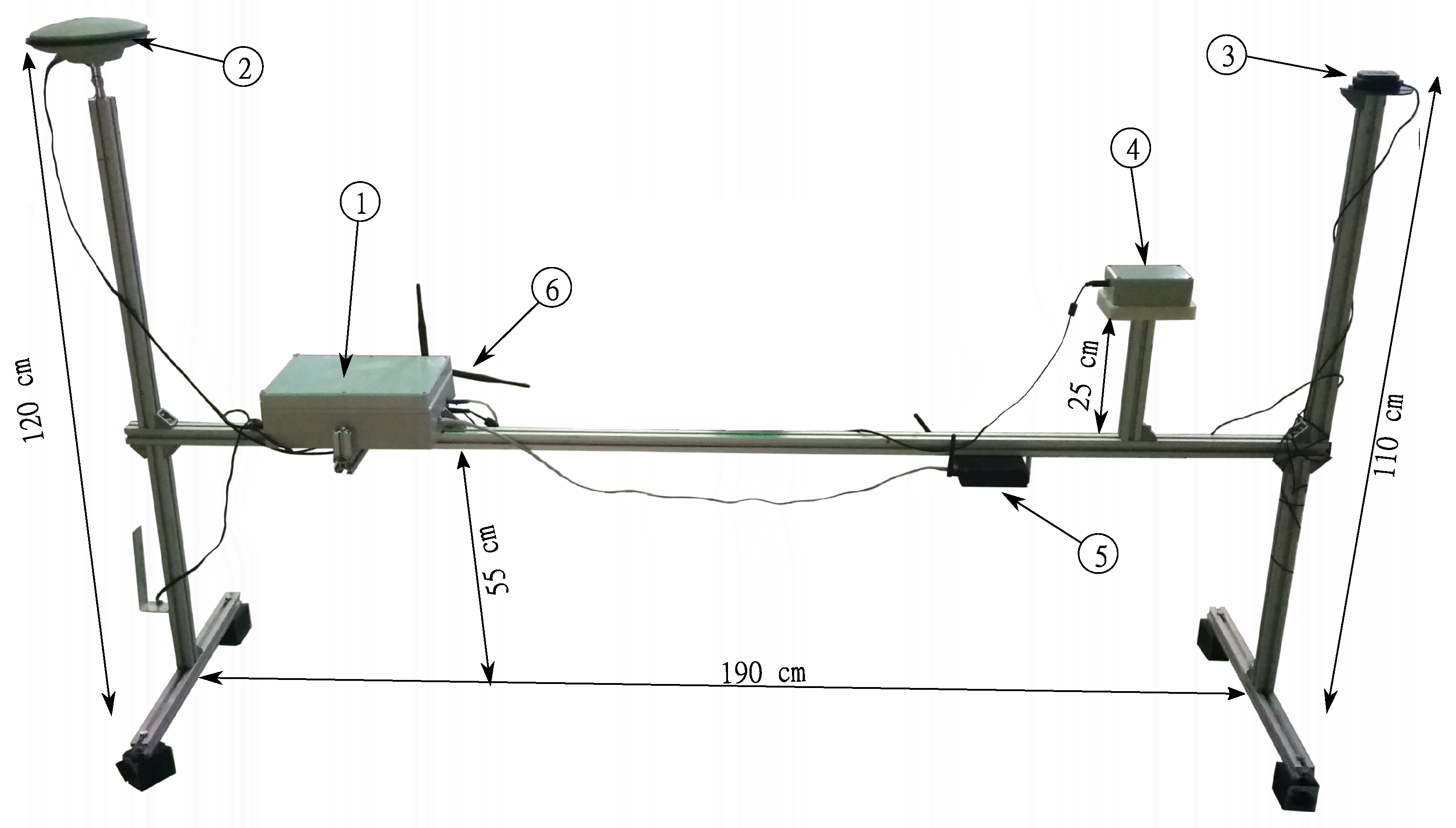
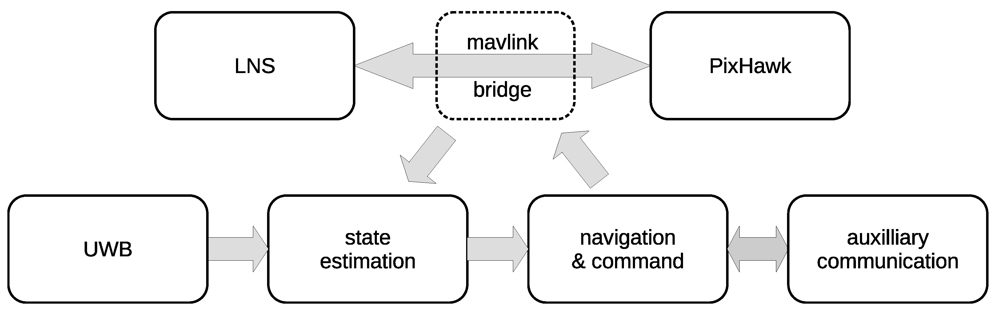
2.3. Navigational Equipment for Landing Pad Position Tracking
- Landing pad navigation station
- Onboard computer
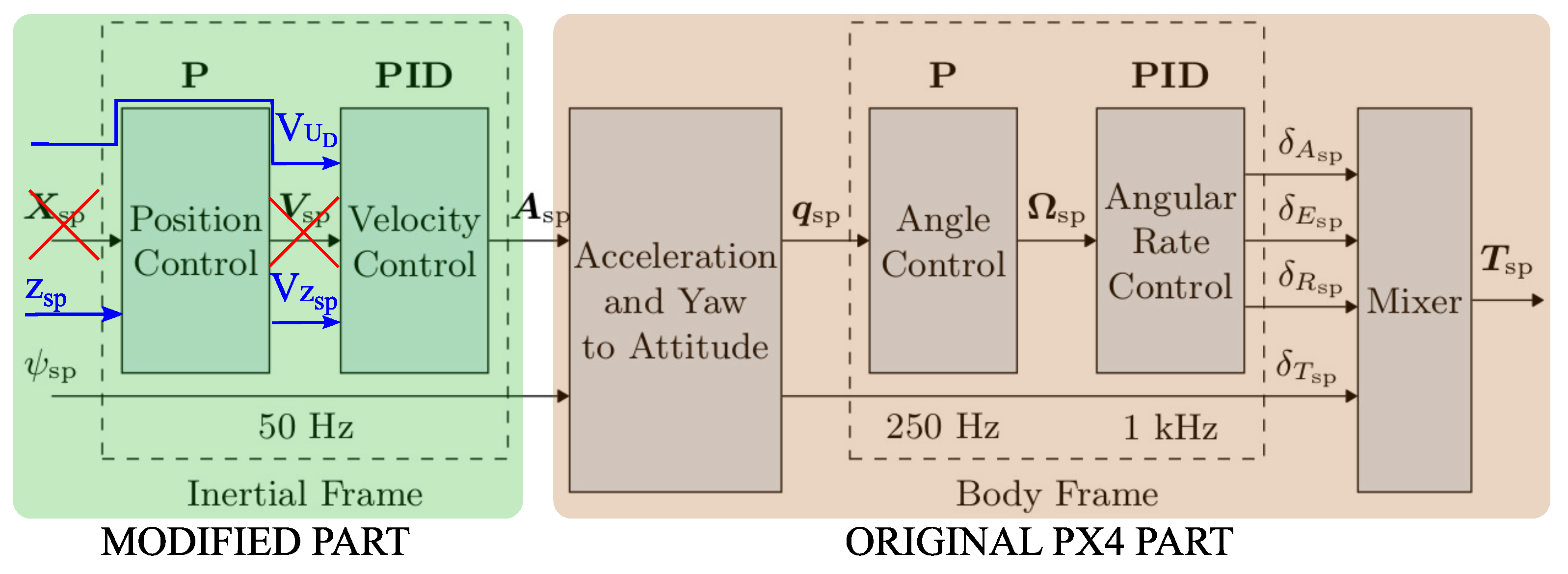
- Autopilot
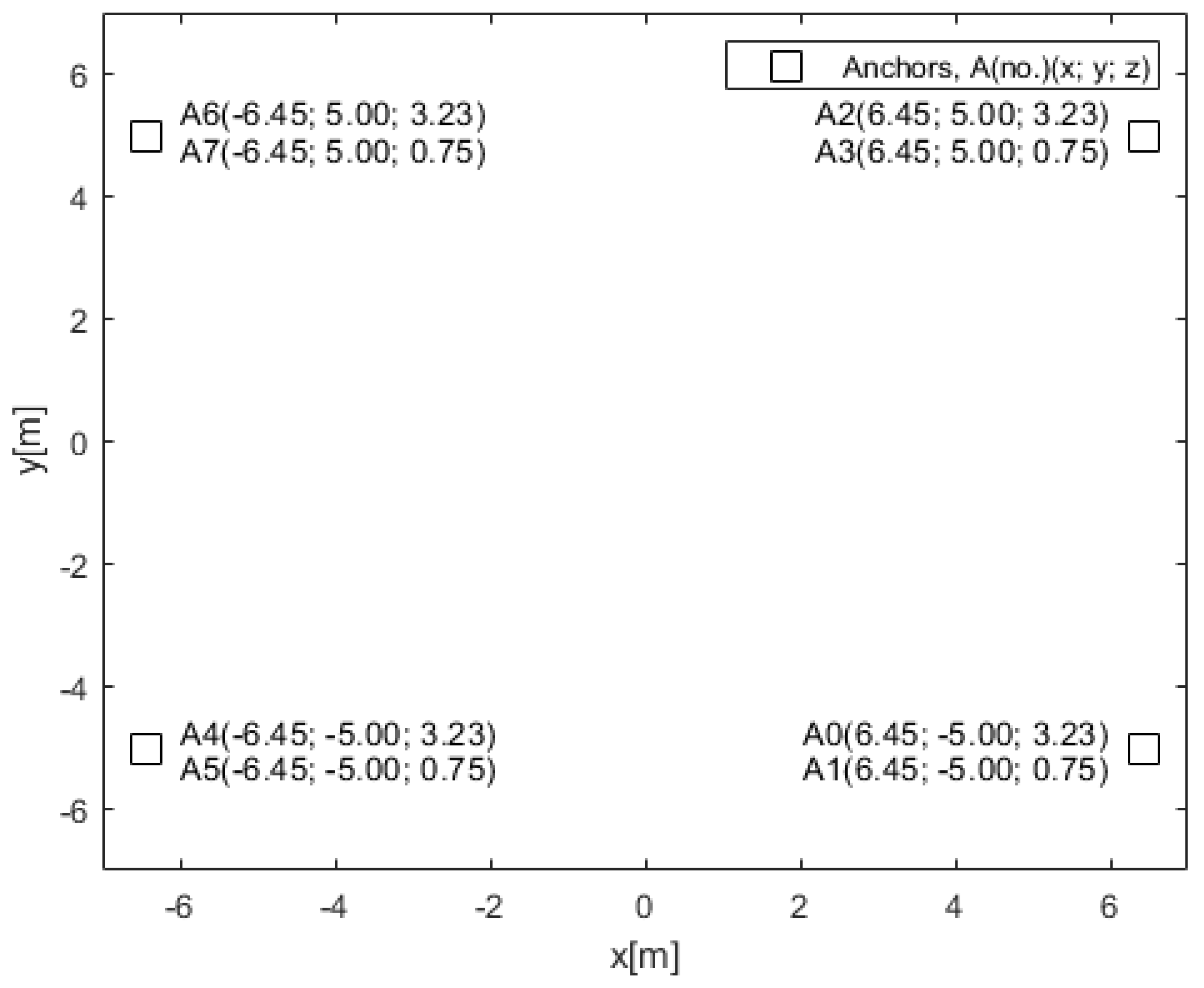
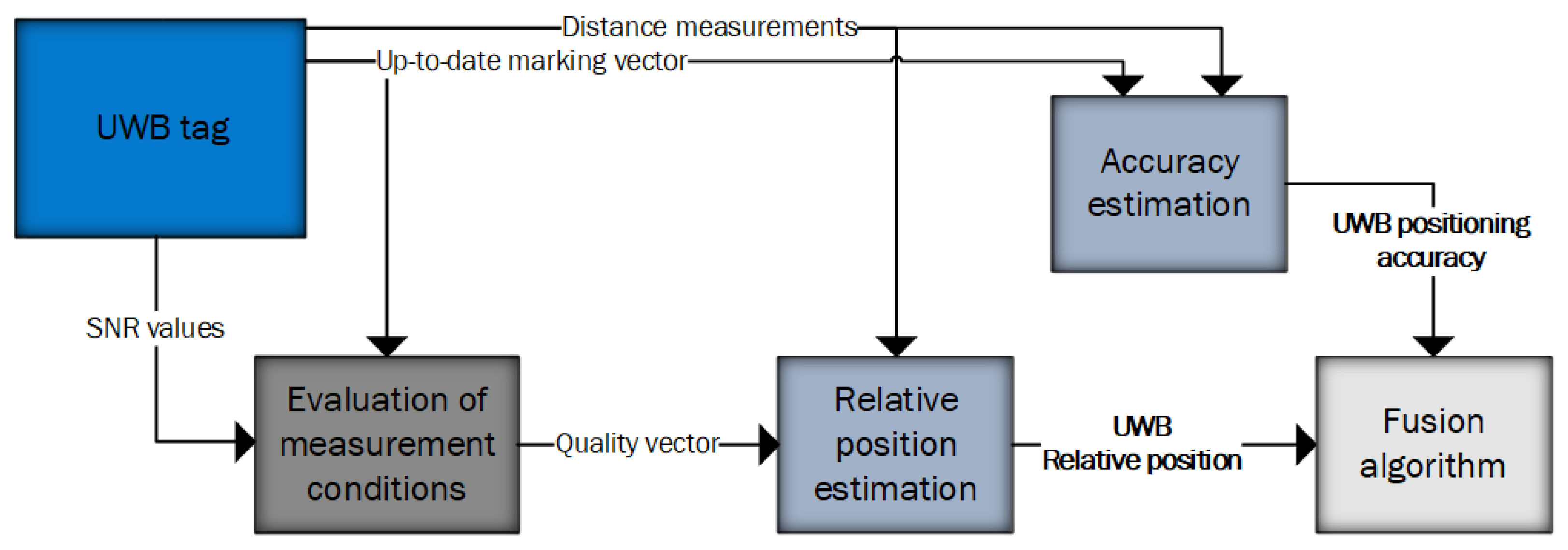
2.4. UWB Positioning System
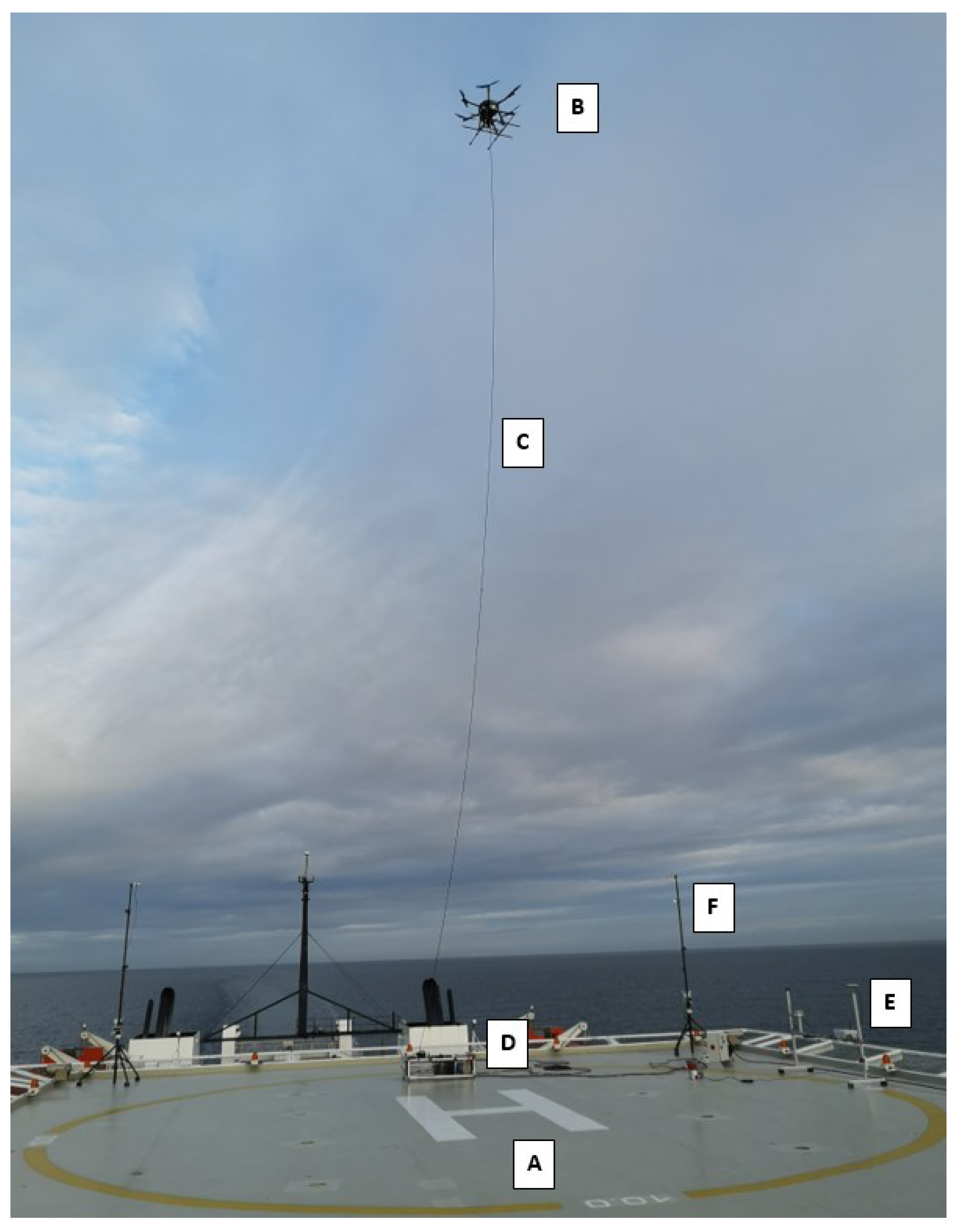
3. Tests on the Ferry in Real Maritime Conditions
- Average temperature: 9 °C;
- Relative wind speed: 11–18 m/s;
- Gusts of wind: up to 22 m/s;
- Cloudiness: 80%;
- Humidity: 74%.
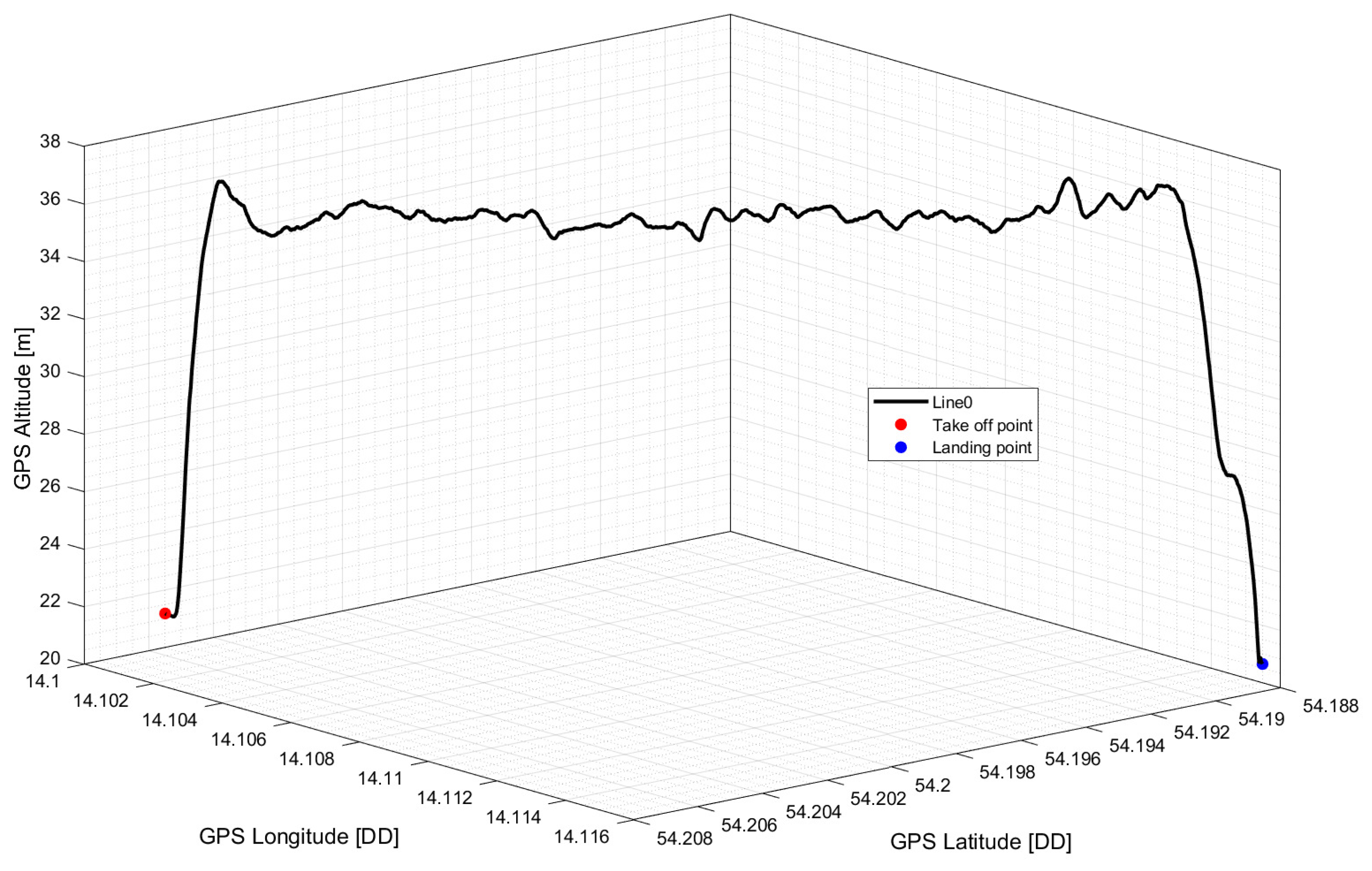
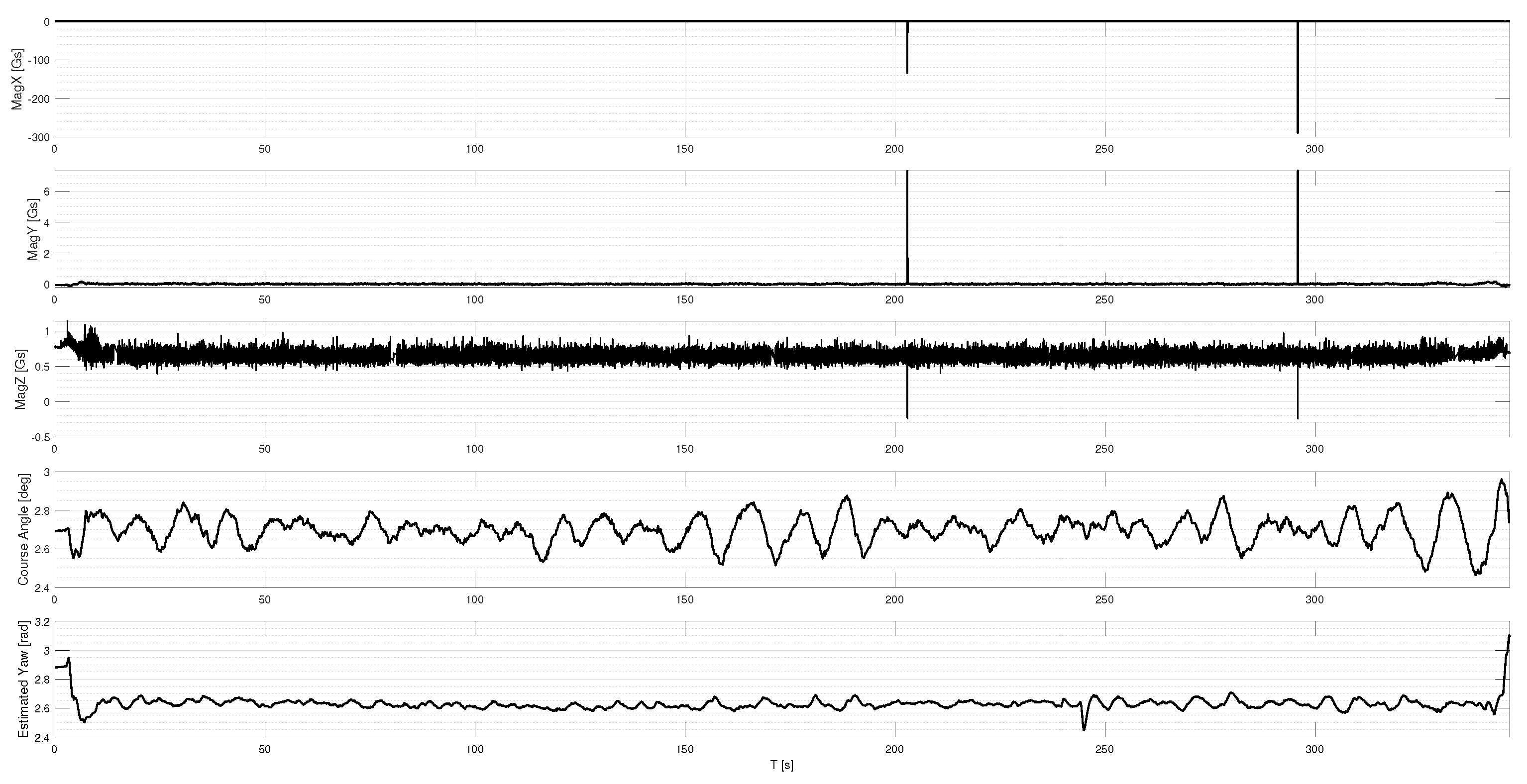
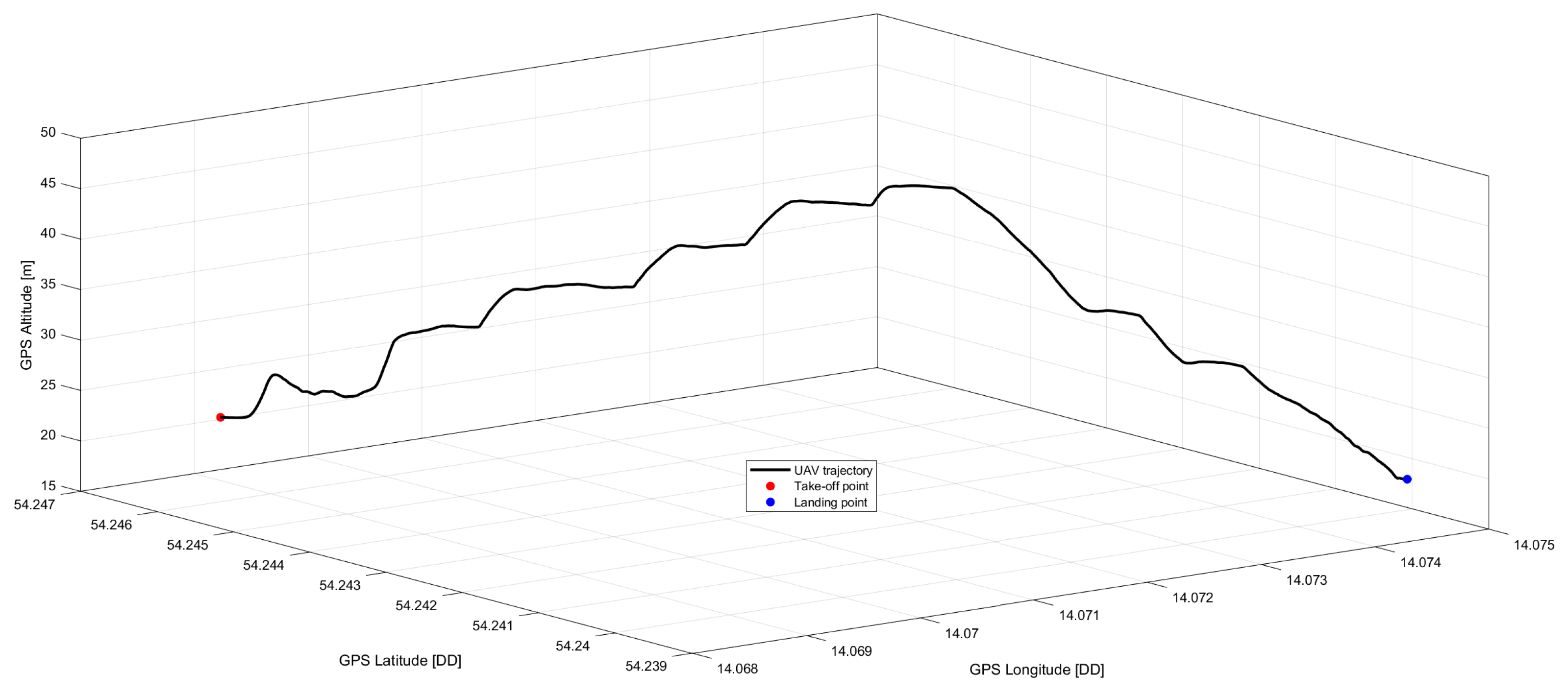
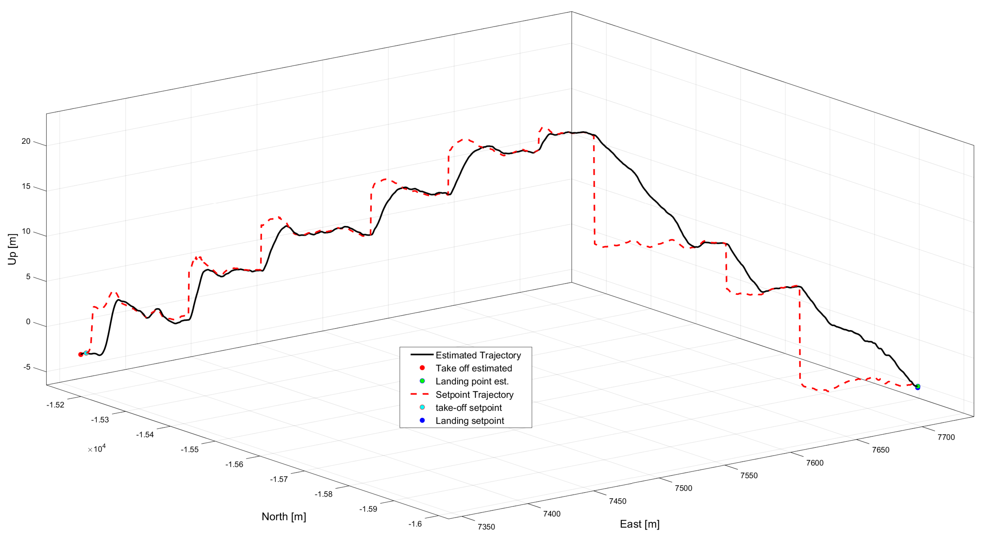
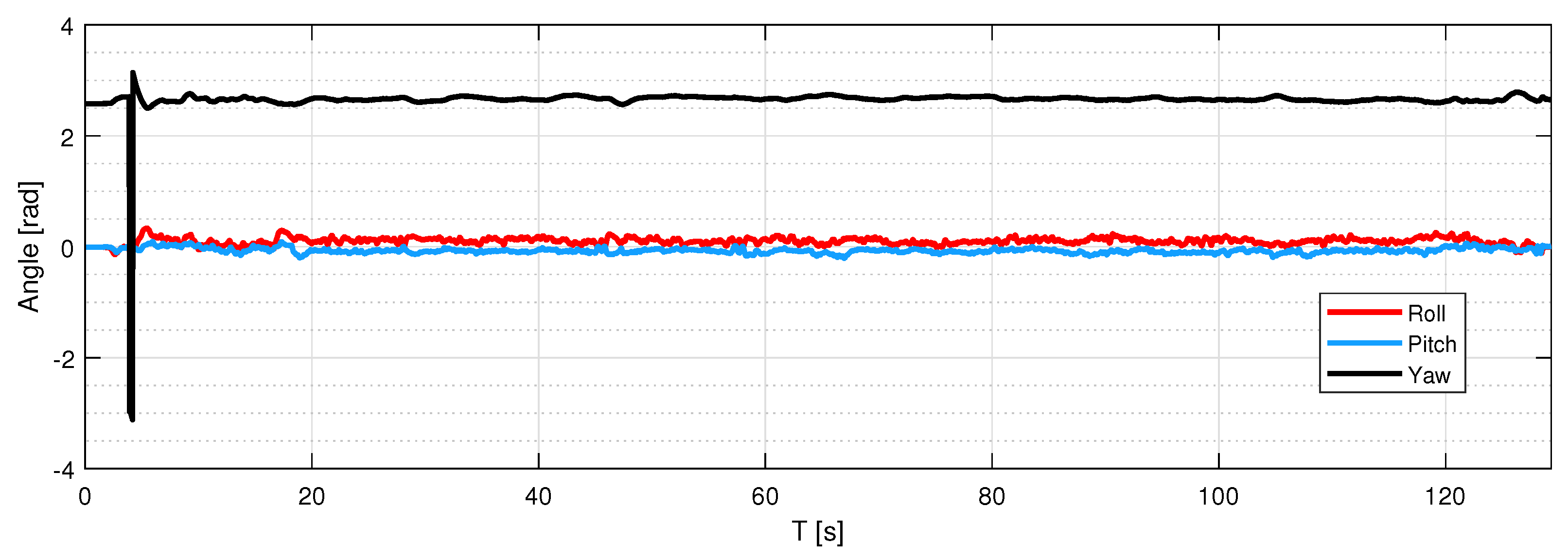
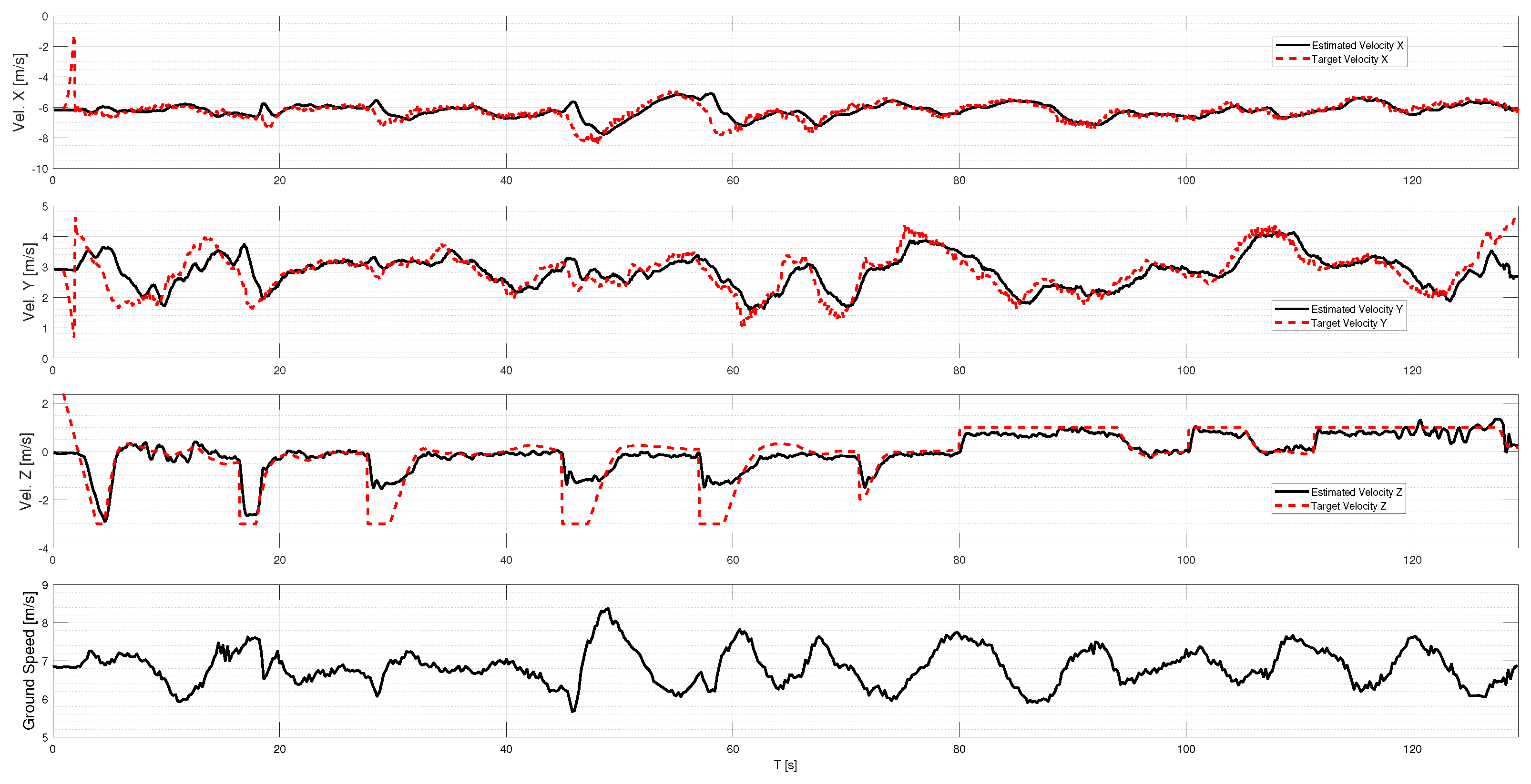
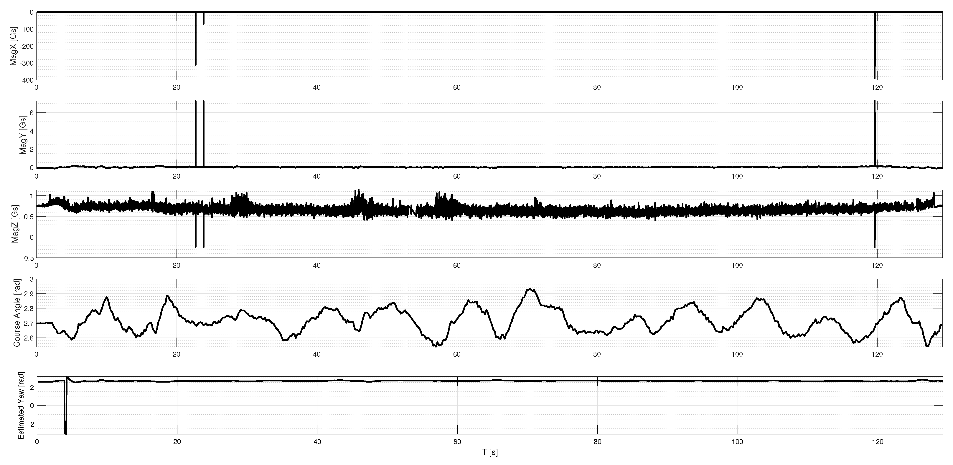
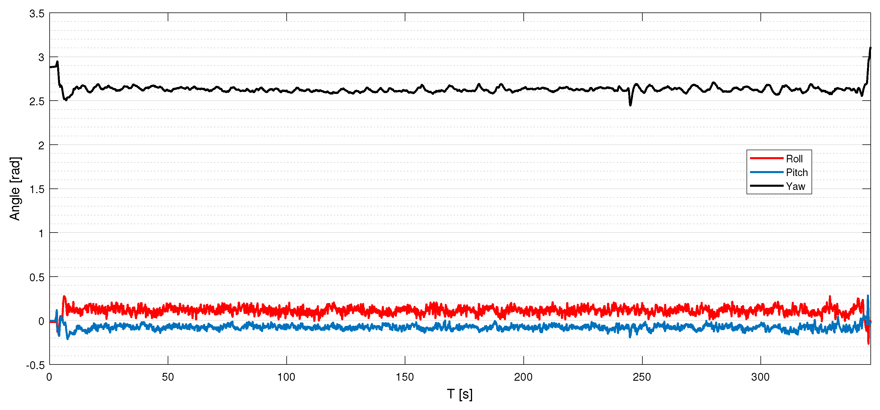
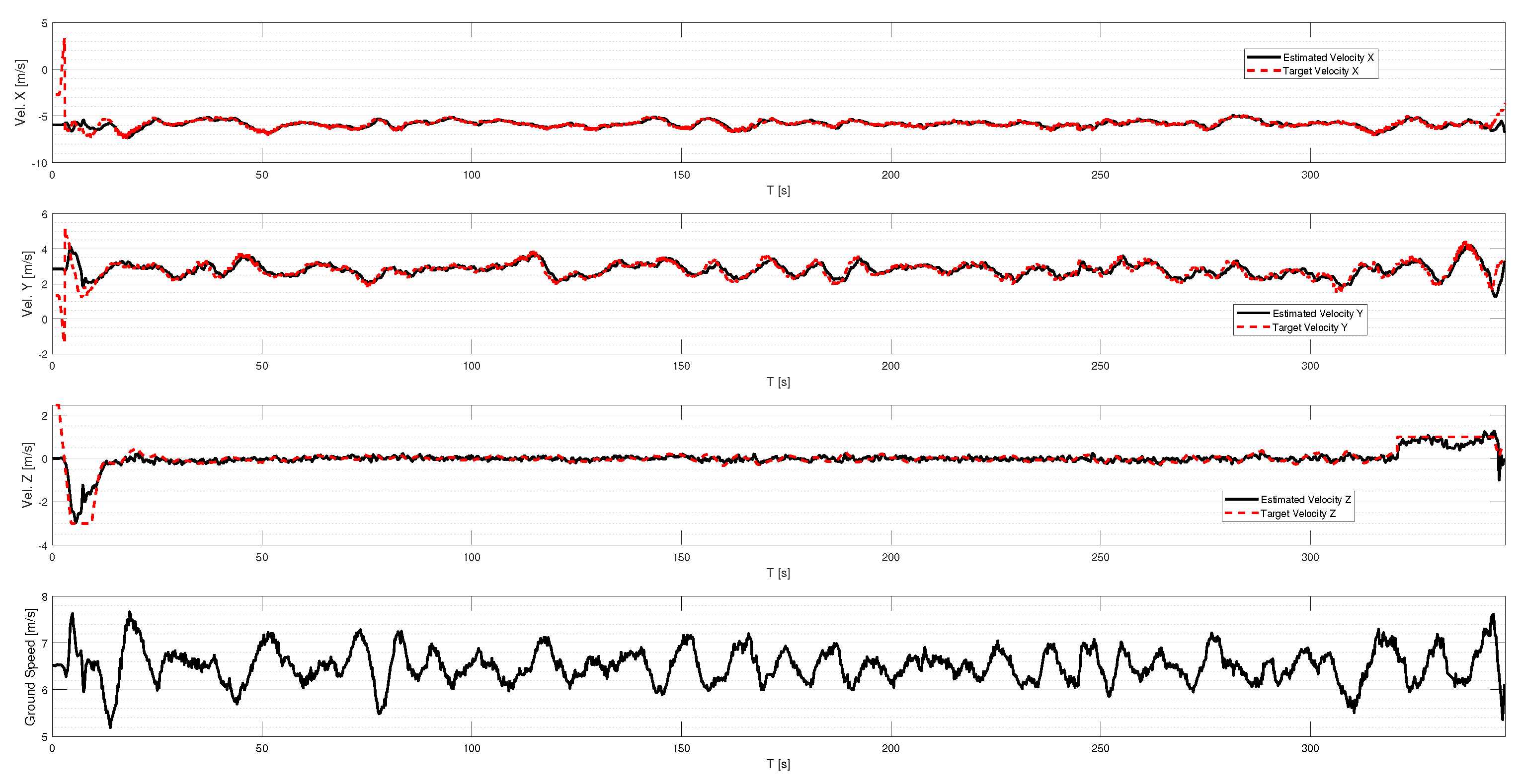
4. Results
5. Conclusions
Author Contributions
Funding
Institutional Review Board Statement
Informed Consent Statement
Data Availability Statement
Conflicts of Interest
Abbreviations
| AC | Alternating current |
| AC/DC | Alternating current/direct current |
| AWG | American wire gauge |
| BLDC | BrushLess direct current |
| DNN | Deep neural network |
| ENU | East-north-up |
| GAN | Generative adversarial network |
| GNSS | Global navigation satellite systems |
| IMU | Inertial measurement unit |
| LIDAR | Light detection and ranging |
| LNS | Landing pad navigation station |
| ROS | Robotic operating system |
| RTCM | Real-time correction message |
| RTK | Real-time kinematics |
| SAR | Search and rescue |
| SNR | Signal-to-noise ratio |
| SR | Super-resolution |
| UART | Universal asynchronous receiver-transmitter |
| UAV | Unmanned aerial vehicle |
| USB | Universal serial bus |
| USV | Unmanned sea vehicle |
| UWB | Ultra-wideband |
| VAC | Volts alternating current |
| VTOL | Vertical takeoff and landing |
| WGS-84 | World Geodetic System ’84 |
References
- Wei, L.; Tao, Z.; Shengjun, H.; Kaiwen, L. A hybrid optimization framework for UAV reconnaissance mission planning. Comput. Ind. Eng. 2022, 173, 108653. [Google Scholar] [CrossRef]
- Santos, N.P.; Rodrigues, V.B.; Pinto, A.B.; Damas, B. Automatic Detection of Civilian and Military Personnel in Reconnaissance Missions using a UAV. In Proceedings of the 2023 IEEE International Conference on Autonomous Robot Systems and Competitions (ICARSC), Tomar, Portugal, 26–27 April 2023; pp. 157–162. [Google Scholar] [CrossRef]
- Ahmadian, N.; Lim, G.J.; Torabbeigi, M.; Kim, S.J. Smart border patrol using drones and wireless charging system under budget limitation. Comput. Ind. Eng. 2022, 164, 107891. [Google Scholar] [CrossRef]
- Namburu, A.; Selvaraj, P.; Mohan, S.; Ragavanantham, S.; Eldin, E.T. Forest Fire Identification in UAV Imagery Using X-MobileNet. Electronics 2023, 12, 733. [Google Scholar] [CrossRef]
- Li, Y.; Yuan, H.; Wang, Y.; Xiao, C. GGT-YOLO: A Novel Object Detection Algorithm for Drone-Based Maritime Cruising. Drones 2022, 6, 335. [Google Scholar] [CrossRef]
- Muttin, F. Umbilical deployment modeling for tethered UAV detecting oil pollution from ship. Appl. Ocean Res. 2011, 33, 332–343. [Google Scholar] [CrossRef]
- Kownacki, C.; Ambroziak, L.; Ciezkowski, M.; Wolniakowski, A.; Romaniuk, S.; Bożko, A.; Oldziej, D. Precision Landing Tests of Tethered Multicopter and VTOL UAV on Moving Landing Pad on a Lake. Sensors 2023, 23, 2016. [Google Scholar] [CrossRef]
- Colomina, I.; Molina, P. Unmanned aerial systems for photogrammetry and remote sensing: A review. ISPRS J. Photogramm. Remote Sens. 2014, 92, 79–97. [Google Scholar] [CrossRef]
- Agrafiotis, P.; Skarlatos, D.; Georgopoulos, A.; Karantzalos, K. Shallow Water Bathymetry Mapping from UAV Imagery Based on Machine Learning. Int. Arch. Photogramm. Remote Sens. Spat. Inf. Sci. 2019, XLII-2/W10, 9–16. [Google Scholar] [CrossRef]
- Burdziakowski, P. Increasing the Geometrical and Interpretation Quality of Unmanned Aerial Vehicle Photogrammetry Products Using Super-resolution Algorithms. Remote Sens. 2020, 12, 810. [Google Scholar] [CrossRef]
- Dhaliwal, S.S.; Ramirez-Serrano, A. Control of an unconventional VTOL UAV for search and rescue operations within confined spaces based on the Marc control architecture. In Proceedings of the 2009 IEEE International Workshop on Safety, Security Rescue Robotics (SSRR 2009), Denver, CO, USA, 3–6 November 2009; IEEE: Piscataway, NJ, USA, 2009; pp. 1–6. [Google Scholar]
- Fabiani, P.; Fuertes, V.; Piquereau, A.; Mampey, R.; Teichteil-Königsbuch, F. Autonomous flight and navigation of VTOL UAVs: From autonomy demonstrations to out-of-sight flights. Aerosp. Sci. Technol. 2007, 11, 183–193. [Google Scholar] [CrossRef]
- Okulski, M.; Ławryńczuk, M. A Small UAV Optimized for Efficient Long-Range and VTOL Missions: An Experimental Tandem-Wing Quadplane Drone. Appl. Sci. 2022, 12, 7059. [Google Scholar] [CrossRef]
- Lewicka, O.; Specht, M.; Specht, C. Assessment of the Steering Precision of a UAV along the Flight Profiles Using a GNSS RTK Receiver. Remote Sens. 2022, 14, 6127. [Google Scholar] [CrossRef]
- Dąbrowski, P.S.; Specht, C.; Specht, M.; Burdziakowski, P.; Makar, A.; Lewicka, O. Integration of Multi-source Geospatial Data from GNSS Receivers, Terrestrial Laser Scanners, and Unmanned Aerial Vehicles. Can. J. Remote Sens. 2021, 47, 621–634. [Google Scholar] [CrossRef]
- Yang, B.; Yang, E. A Survey on Radio Frequency based Precise Localisation Technology for UAV in GPS-denied Environment. J. Intell. Robot. Syst. 2021, 103, 38. [Google Scholar] [CrossRef]
- Paul, H.; Miyazaki, R.; Kominami, T.; Ladig, R.; Shimonomura, K. A Versatile Aerial Manipulator Design and Realization of UAV Take-Off from a Rocking Unstable Surface. Appl. Sci. 2021, 11, 9157. [Google Scholar] [CrossRef]
- Tang, H.; Zhang, D.; Gan, Z. Control System for Vertical Take-Off and Landing Vehicle’s Adaptive Landing Based on Multi-Sensor Data Fusion. Sensors 2020, 20, 4411. [Google Scholar] [CrossRef]
- Chang, C.-W.; Lo, L.-Y.; Cheung, H.C.; Feng, Y.; Yang, A.-S.; Wen, C.-Y.; Zhou, W. Proactive Guidance for Accurate UAV Landing on a Dynamic Platform: A Visual–Inertial Approach. Sensors 2022, 22, 404. [Google Scholar] [CrossRef]
- Grlj, C.G.; Krznar, N.; Pranjić, M. A Decade of UAV Docking Stations: A Brief Overview of Mobile and Fixed Landing Platforms. Drones 2022, 6, 17. [Google Scholar] [CrossRef]
- Acevedo, J.J.; García, M.; Viguria, A.; Ramón, P.; Arrue, B.C.; Ollero, A. Autonomous Landing of a Multicopter on a Moving Platform Based on Vision Techniques. In Proceedings of the ROBOT 2017: Third Iberian Robotics Conference, ROBOT 2017, Sevilla, Spain, 22–24 November 2017; Ollero, A., Sanfeliu, A., Montano, L., Lau, N., Cardeira, C., Eds.; Advances in Intelligent Systems and Computing. Springer: Cham, Sweitzerland, 2017; Volume 694. [Google Scholar]
- Shao, G.; Ma, Y.; Malekian, R.; Yan, X.; Li, Z. A Novel Cooperative Platform Design for Coupled USV–UAV Systems. IEEE Trans. Ind. Inform. 2019, 15, 4913–4922. [Google Scholar] [CrossRef]
- Narváez, E.; Ravankar, A.A.; Ravankar, A.; Emaru, T.; Kobayashi, Y. Autonomous VTOL-UAV Docking System for Heterogeneous Multirobot Team. IEEE Trans. Instrum. Meas. 2021, 70, 5500718. [Google Scholar] [CrossRef]
- Palafox, P.R.; Garzón, M.; Valente, J.; Roldán, J.J.; Barrientos, A. Robust Visual-Aided Autonomous Takeoff, Tracking, and Landing of a Small UAV on a Moving Landing Platform for Life-Long Operation. Appl. Sci. 2019, 9, 2661. [Google Scholar] [CrossRef]
- Alarcón, F.; García, M.; Maza, I.; Viguria, A.; Ollero, A. A Precise and GNSS-Free Landing System on Moving Platforms for Rotary-Wing UAVs. Sensors 2019, 19, 886. [Google Scholar] [CrossRef] [PubMed]
- Aissi, M.; Moumen, Y.; Berrich, J.; Bouchentouf, T.; Bourhaleb, M.; Rahmoun, M. Autonomous solar USV with an automated launch and recovery system for UAV: State of the art and Design. In Proceedings of the 2020 IEEE 2nd International Conference on Electronics, Control, Optimization and Computer Science (ICECOCS), Kenitra, Morocco, 2–3 December 2020; pp. 1–6. [Google Scholar]
- Kontron. pITX-E38, ULTRASMALL 2.5” Pico-ITX BOARD WITH Intel® Atom™ E38XX; Kontron: Augsburg, Germany, 2016. [Google Scholar]
- U-blox. NEO-M8P U-blox M8 High Precision GNSS Modules; No. UBX-15016656; U-blox: Thalwil, Switzerland, 2020. [Google Scholar]
- Sparton. AHRS-8, Attitude Heading Reference System; No. 12.21.17; Sparton: Schaumburg, IL, USA, 2017. [Google Scholar]
- PX4 Autopilot User Guide (Main). Available online: https://docs.px4.io/main/en/ (accessed on 29 May 2023).
- PX4 Controller Diagrams. Available online: https://docs.px4.io/main/en/flight_stack/controller_diagrams.html (accessed on 29 May 2023).
- Barral, V.; Escudero, C.J.; García-Naya, J.A. NLOS Classification Based on RSS and Ranging Statistics Obtained from Low-Cost UWB Devices. In Proceedings of the 27th European Signal Processing Conference (EUSIPCO), A Coruna, Spain, 2–6 September 2019; pp. 1–5. [Google Scholar] [CrossRef]
- Janczak, D.; Walendziuk, W.; Sadowski, M.; Zankiewicz, A.; Konopko, K.; Idzkowski, A. Accuracy Analysis of the Indoor Location System Based on Bluetooth Low-Energy RSSI Measurements. Energies 2022, 15, 8832. [Google Scholar] [CrossRef]


| Parameter | Value |
|---|---|
| Distance between opposite motors | 960 mm |
| Wheelbase diameter (top view) | 1400 mm |
| Max. single-drive thrust | 40 N |
| Max. take-off mass | 13.5 kg |
| Payload | 3 kg |
| Power type and source | Electric, tethered from ground (vessel) |
| Motor type | Brushless DC motor |
| Wind resistance | 16.6 m/s |
| Flight duration | Unlimited * |
Disclaimer/Publisher’s Note: The statements, opinions and data contained in all publications are solely those of the individual author(s) and contributor(s) and not of MDPI and/or the editor(s). MDPI and/or the editor(s) disclaim responsibility for any injury to people or property resulting from any ideas, methods, instructions or products referred to in the content. |
© 2023 by the authors. Licensee MDPI, Basel, Switzerland. This article is an open access article distributed under the terms and conditions of the Creative Commons Attribution (CC BY) license (https://creativecommons.org/licenses/by/4.0/).
Share and Cite
Kownacki, C.; Ambroziak, L.; Ciężkowski, M.; Wolniakowski, A.; Romaniuk, S.; Kulesza, Z.; Bożko, A.; Ołdziej, D. Development and Evaluation of a Tethered Class C3 Hexacopter in Maritime Conditions on the Helipad of a Ferry. Appl. Sci. 2023, 13, 9396. https://doi.org/10.3390/app13169396
Kownacki C, Ambroziak L, Ciężkowski M, Wolniakowski A, Romaniuk S, Kulesza Z, Bożko A, Ołdziej D. Development and Evaluation of a Tethered Class C3 Hexacopter in Maritime Conditions on the Helipad of a Ferry. Applied Sciences. 2023; 13(16):9396. https://doi.org/10.3390/app13169396
Chicago/Turabian StyleKownacki, Cezary, Leszek Ambroziak, Maciej Ciężkowski, Adam Wolniakowski, Sławomir Romaniuk, Zbigniew Kulesza, Arkadiusz Bożko, and Daniel Ołdziej. 2023. "Development and Evaluation of a Tethered Class C3 Hexacopter in Maritime Conditions on the Helipad of a Ferry" Applied Sciences 13, no. 16: 9396. https://doi.org/10.3390/app13169396
APA StyleKownacki, C., Ambroziak, L., Ciężkowski, M., Wolniakowski, A., Romaniuk, S., Kulesza, Z., Bożko, A., & Ołdziej, D. (2023). Development and Evaluation of a Tethered Class C3 Hexacopter in Maritime Conditions on the Helipad of a Ferry. Applied Sciences, 13(16), 9396. https://doi.org/10.3390/app13169396