Article

Seismic Reduction Analysis of Super-Long Span Suspension Bridge with Lattice Composite Tower and Damping System: A Case of Study for Qiongzhou Strait Bridge

1
College of Computer Science and Technology, Heilongjiang Institute of Technology, Harbin 150050, China
2
School of Civil Engineering, Harbin Institute of Technology, Harbin 150090, China
3
Department of Civil Engineering, Harbin Institute of Technology at Weihai, Weinhai 264209, China
*
Author to whom correspondence should be addressed.
Appl. Sci. 2023, 13(16), 9387; https://doi.org/10.3390/app13169387
Submission received: 23 June 2023 / Revised: 6 August 2023 / Accepted: 16 August 2023 / Published: 18 August 2023

Abstract

:
In this paper, we proposed a lattice composite tower damping system to reduce the seismic response of super-long-span suspension bridges. Taking the QiongZhou strait bridge as a case study, we evaluated seismic performances through a finite element analysis (FEA) and shaking-table tests. First, the seismic responses of a super-long-span suspension bridge with or without a lattice composite tower to far-fault and near-fault earthquakes were analyzed and compared. The influence of the lattice composite tower on the dynamic characteristics and seismic performance was then investigated using shaking-table tests. Finally, the influences of different damping systems on the seismic response were evaluated, considering factors such as the damper type, damper arrangement scheme and design parameters. The results indicated that lattice composite tower could significantly increase the seismic performance of super-long span suspension bridge, while the optimal damping system could markedly improve the energy dissipation ability of whole system. Subsequently, this could provide references to enhance the seismic safety of the super-long span suspension bridge under strong earthquakes.

1. Introduction

In recent decades, long-span suspension bridges have been built all over the world; several are located in regions near fault-crossing sites [1]. The main tower columns of a super-long-span suspension bridge are much higher than those of long-span suspension bridges; thus, seismic control devices and measures are of greater importance for the safety of the former. In the traditional seismic design of bridges, structural components of the bridge are allowed to enter a nonlinear state to dissipate energy when exposed to strong earthquakes [2]. For the bridge tower of long-span suspension bridges, the traditional design view often treats each main tower column as one independent section component [3,4]. An independent tower column structure has good overall integrity and is simple to construct.
Previous studies have shown that bridge structures are easily damaged because of extreme events such as strong earthquakes [5,6,7]. Dampers have been widely adopted in industries for several decades, including aerospace, the military and automobiles [8,9]. The damping system is also an important structural protection system for important bridge structure, and it has been widely investigated and adopted in bridges in China since the 1990s [10,11]. A damping system is an important structural protection system for bridge structures. Recent research indicates that most of the long-span suspension bridges around the world have installed damping systems as shock absorbers or energy dissipation systems. Many types of damper have been installed in bridges to improve the dynamic performance of the bridge when exposed to wind or earthquake excitation [12,13,14]. The towers in long-span bridges are generally slender with large height, and the location and distribution of energy dissipation devices for the towers are important factors to be considered [15]. The traditional seismic response control strategies for long-span bridges mainly focused on the damping connection [16] or damped outriggers between the tower column and bridge deck [17]. In order to reduce the structure self-weight and improve the mechanical performance of the super-long span cable-stayed bridge under earthquake and wind excitation, the CFRP cables and UHPC members were designed and analyzed [18,19].
The large retrofit costs of bridges after the Chi-Chi earthquake in 1999 revealed the need for alternative bridge design strategies, including improved performance when exposed to a near-fault earthquake. In China, the longest bridge crossing an active fault is the Puqian Bridge in Hainan Province [3]. It has been observed that bridges located in near-fault areas are more vulnerable when exposed to earthquakes [19,20]. Near-fault earthquakes possess distinct characteristics [21], including the high-velocity pulse effect, the hanging wall effect, the directivity effect and the fling-step effect [22,23,24,25]. It is necessary to study the influence of near-fault ground motion characteristics on the seismic responses of bridges to reduce seismic damage [26]. Some methods have been proposed to study the seismic responses of long-span suspension bridge under near-fault earthquake, and the seismic response reduction measures are also widely proposed. The responses of long-span cable-stayed bridge under near-fault ground motions considering velocity pulse effect and non-uniform excitation were investigated systematically through shake-table test [27]. The transverse seismic responses of soil-cable-stayed-bridge system under near-fault ground motions were also investigated by both of experimental test and numerical simulation [28]. In terms of research methods, several methods have been proposed to study the seismic responses of long-span bridges exposed to strong earthquakes, including structural health monitoring [29], shaking-table tests [27,30,31], non-destructive on-site tests [32] and numerical simulation [33]. The finite element simulation method is often chosen as one of the preferred methods in the schematic design phase.
With the increase in increments in the main span of a suspension bridge, the height of the bridge tower becomes higher. It is important to investigate the seismic response control measures for main towers to reduce the possibility of a large seismic response. Lattice composite towers can divide a single section into multiple sections, which is convenient for installing energy dissipation devices between adjacent sub-tower columns. This provides a potentially feasible approach to improve the seismic performance of super-long-span suspension bridges. Hence, it is of significance to study the seismic response reduction performance of lattice composite tower damping systems for super-long-span suspension bridges exposed to strong earthquakes.
In this paper, we investigated the seismic performance of a super-long-span suspension bridge exposed to far-fault and near-fault earthquakes and discussed the seismic response with a new type of lattice composite tower and damping system. The nonlinear seismic responses of a super-long-span suspension bridge exposed to far-fault and near-fault earthquakes were analyzed and compared. The dynamic characteristics and seismic response reduction performance of a super-long-span suspension bridge with or without a lattice composite tower were then investigated. The influences of different damping systems on the seismic response of the lattice composite tower system were evaluated, including the damper arrangement scheme and design parameters.

2. Finite Element Model of the Super-Long-Span Suspension Bridge

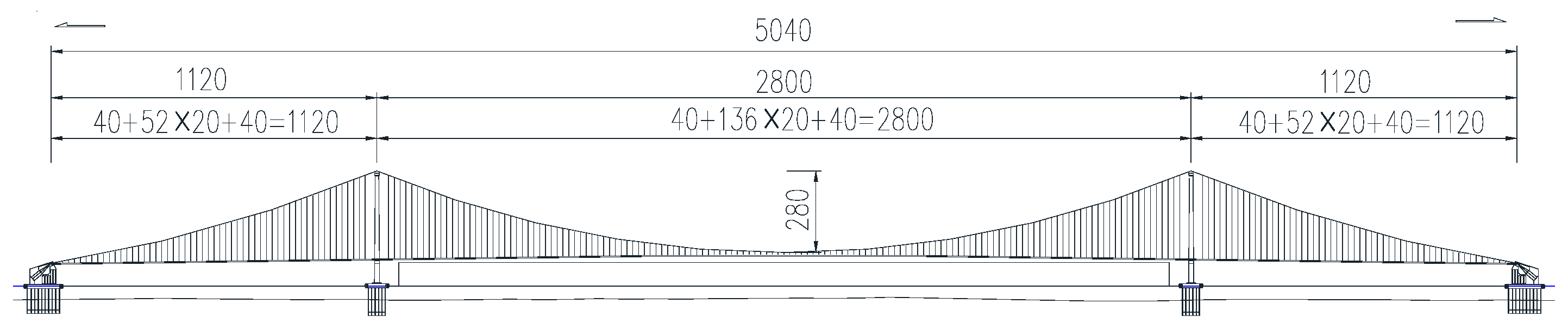
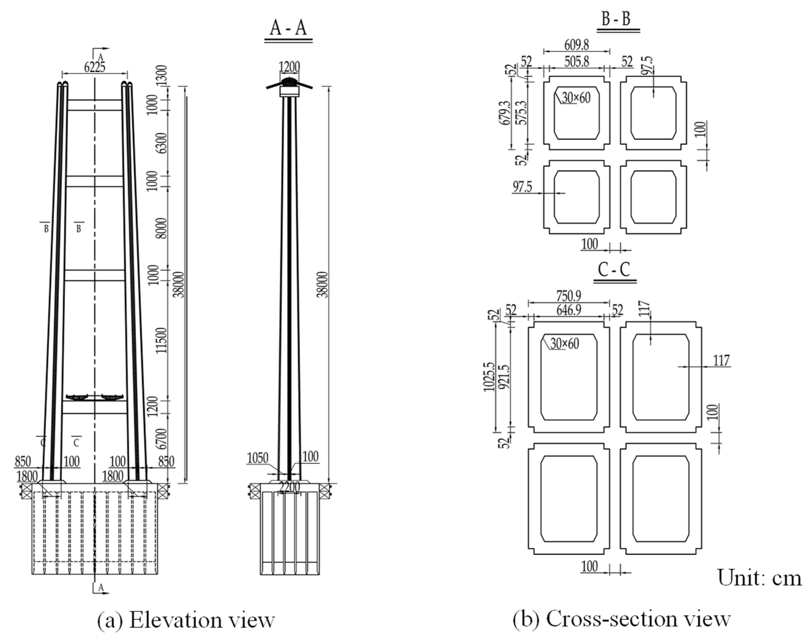
2.1. Super-Long-Span Suspension Bridge Information

Qiongzhou Strait is one of the three major straits in China, with an east–west length of approximately 80 km and an average north–south width of nearly 30 km. The finite element model used in this paper was based on a design model of a super-long-span suspension bridge over the Qiongzhou strait. The overall span size of this long suspension bridge was 5040 m and its main span was 2800 m. The suspension bridge had a longitudinal floating system with a main tower height of 380 m and main cable sag of 280 m. The cross-sectional area of the main cable on one side was 1.517 m2. The stiffening girder was located in a closed-box girder section. The first phase dead load of the main girder was 221 kN/m and the second phase dead load was 80 kN/m. The layout of the super-long-span suspension bridge is shown in Figure 1.
The main parameters of the lattice composite tower and damping system were as follows. The four separated sub-towers used the same cross-section form as the prototype main tower column. The section dimension of each sub-tower in the lattice composite towers was 0.65 times of the original main tower to guarantee the stability. To install the dampers, the spacing between the outer sections of the separated sub-towers was set to 1.0 m. The top of the separated sub-towers was connected by rigid steel beams. The main cable was hinged at the center point of the top of the sub-towers. The details of lattice composite towers of the super-long-span suspension bridge were given in Figure 2.

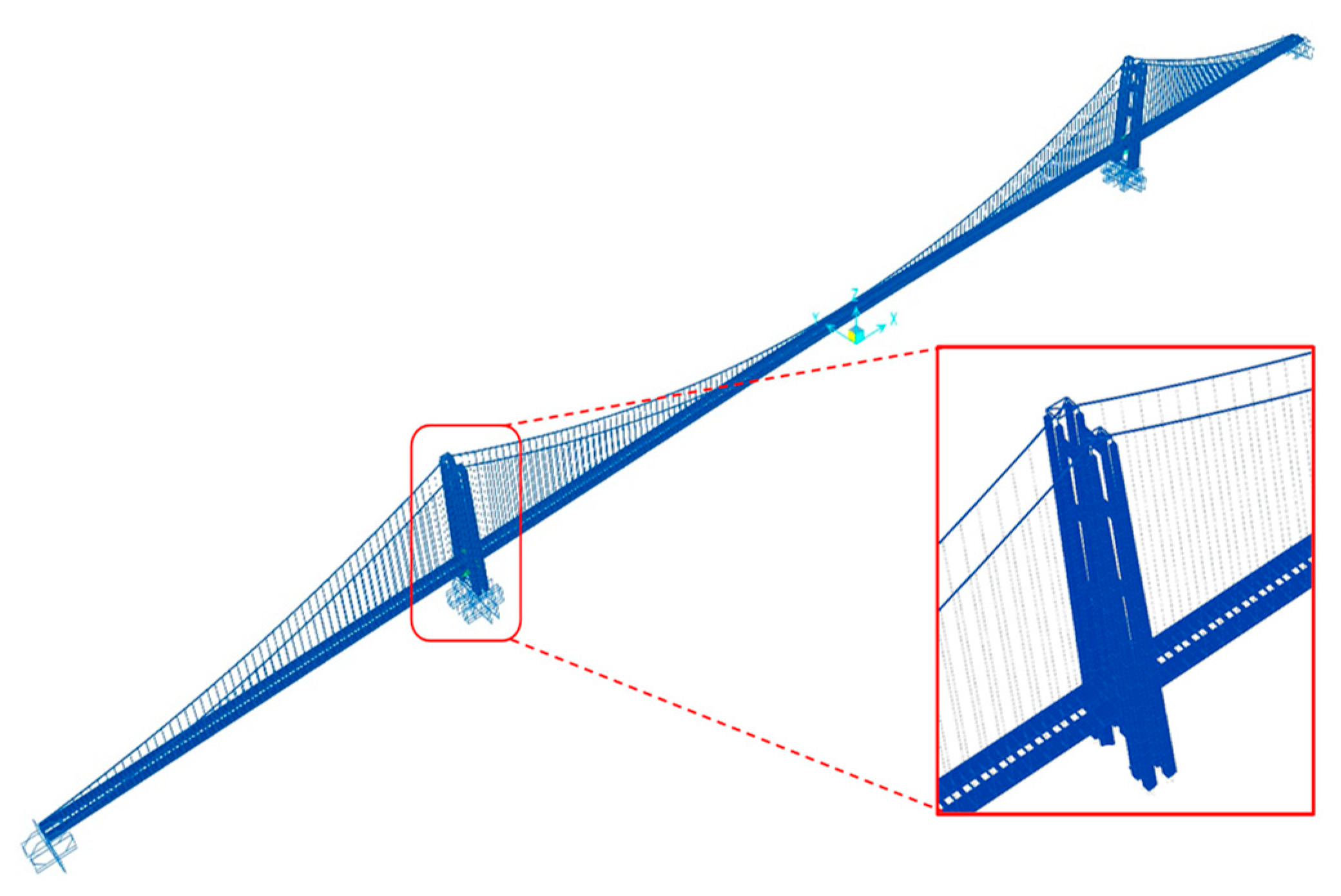
2.2. Finite Element Model

According to the structural characteristics of a suspension bridge, the finite element model of a long-span suspension bridge was established. A three-dimensional (3D) beam element was adopted to simulate the bridge tower and stiffening girder. A 3D truss element was adopted to simulate the suspender of the suspension bridge. A 3D beam element was used to simulate the main cable of the suspension bridge, considering the influence of bending stiffness. A hinged boundary was adopted to simulate the connections between the main cable and the top of the bridge tower, the suspender and the main cable and the suspender and the stiffening girder. This suspension bridge had a longitudinal floating system; the longitudinal displacement constraints between the main girder and the bridge tower were released at the connection of the support. A fixed boundary was selected between the tower and the foundation.
The main cable of the whole bridge was divided into 492 elements; there were 486 suspender truss elements in total. The main tower comprised reinforced concrete (C50) with a longitudinal steel reinforcement ratio of 1%. A variable cross-section was simulated with 24 different sections; each beam was divided into 4 elements. The elastic modulus of the reinforcement and the steel box girder were both 2.01 × 10¹¹ Pa, the Poisson ratio was 0.3 and the second stiffness coefficient was 0.02. The yield stress of the reinforcement was 423 MPa and the yield stress of the steel box girder was 345 MPa. The elastic modulus of the concrete was 3.45 × 10¹⁰ Pa and the Poisson ratio was 0.2. According to the previous damping ratio identification results, either through field testing or laboratory observations, the damping ratio of the first few mode shapes of long-span bridges usually varies between 0.50 and 2.48% [34]. Therefore, the damping ratio for the first two modes of the super-long suspension finite element model was set as 0.8%.
Figure 3 presents the deformation of a super-long-span suspension bridge under a gravity load. This was coincident with the design requirements and proved the accuracy of the finite element model used in this paper.

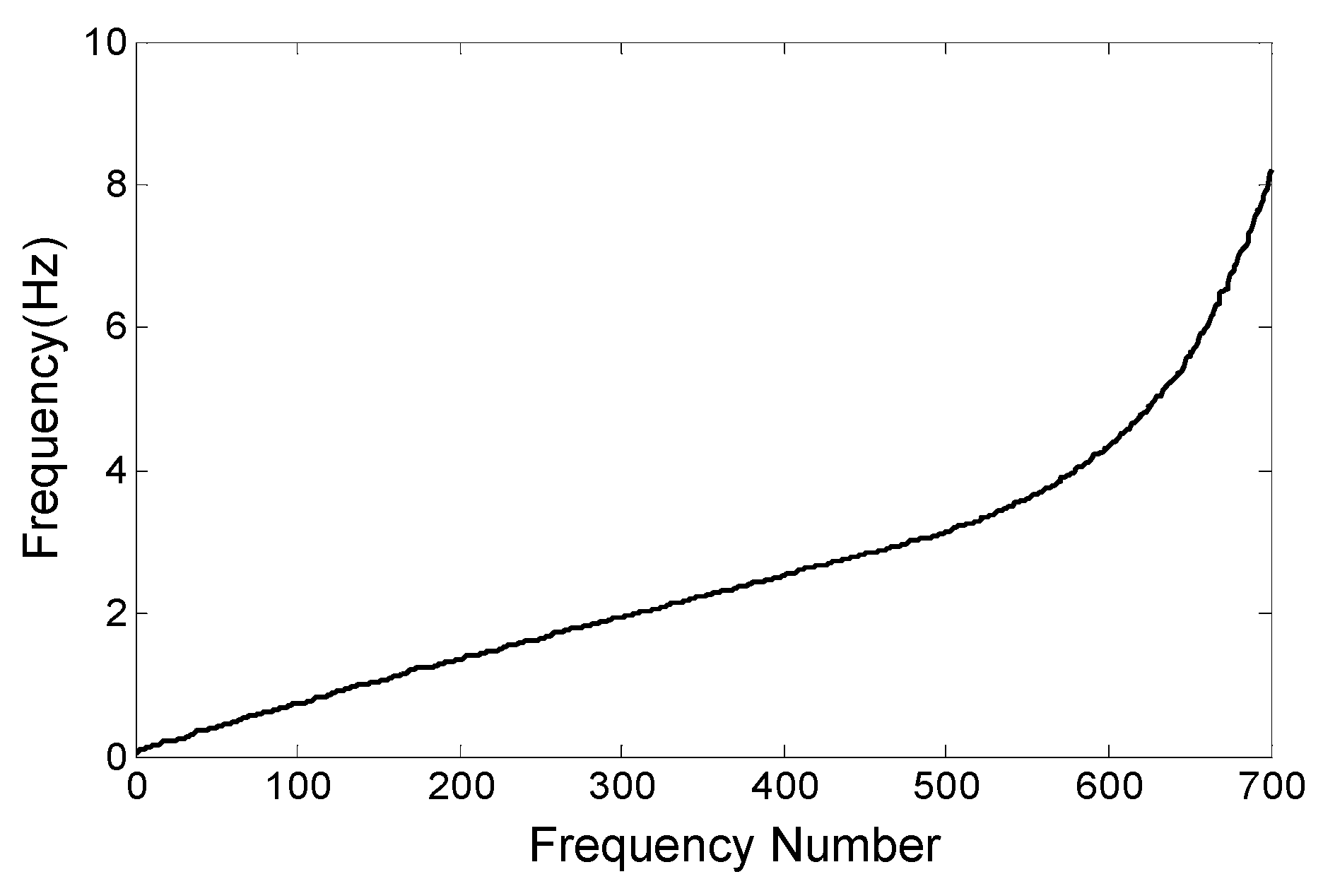
2.3. Dynamic Characteristics

A modal analysis of the finite element model of the super-long-span suspension bridge was performed. The first 700 natural frequencies of the constructed model are shown in Figure 4, and several mode shapes are shown in Figure 5. The results of the dynamic characteristics of the super-long-span suspension bridge agreed with the initial design and previous similar suspension bridges [35,36], also proving the accuracy of the finite element model.

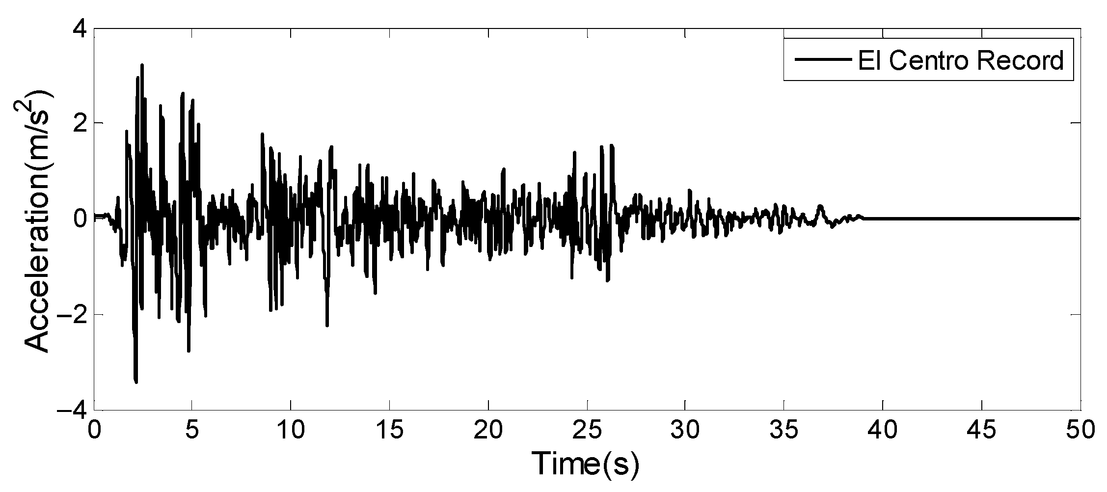
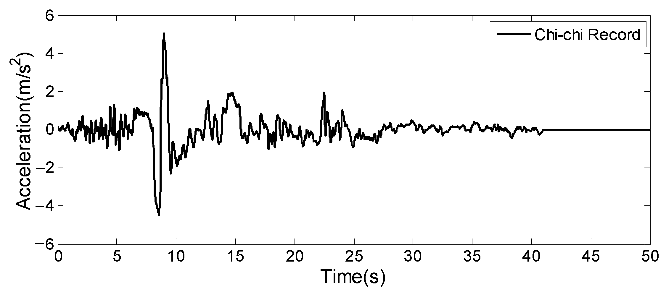
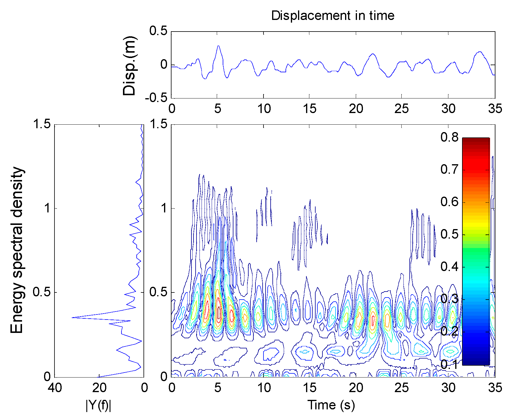
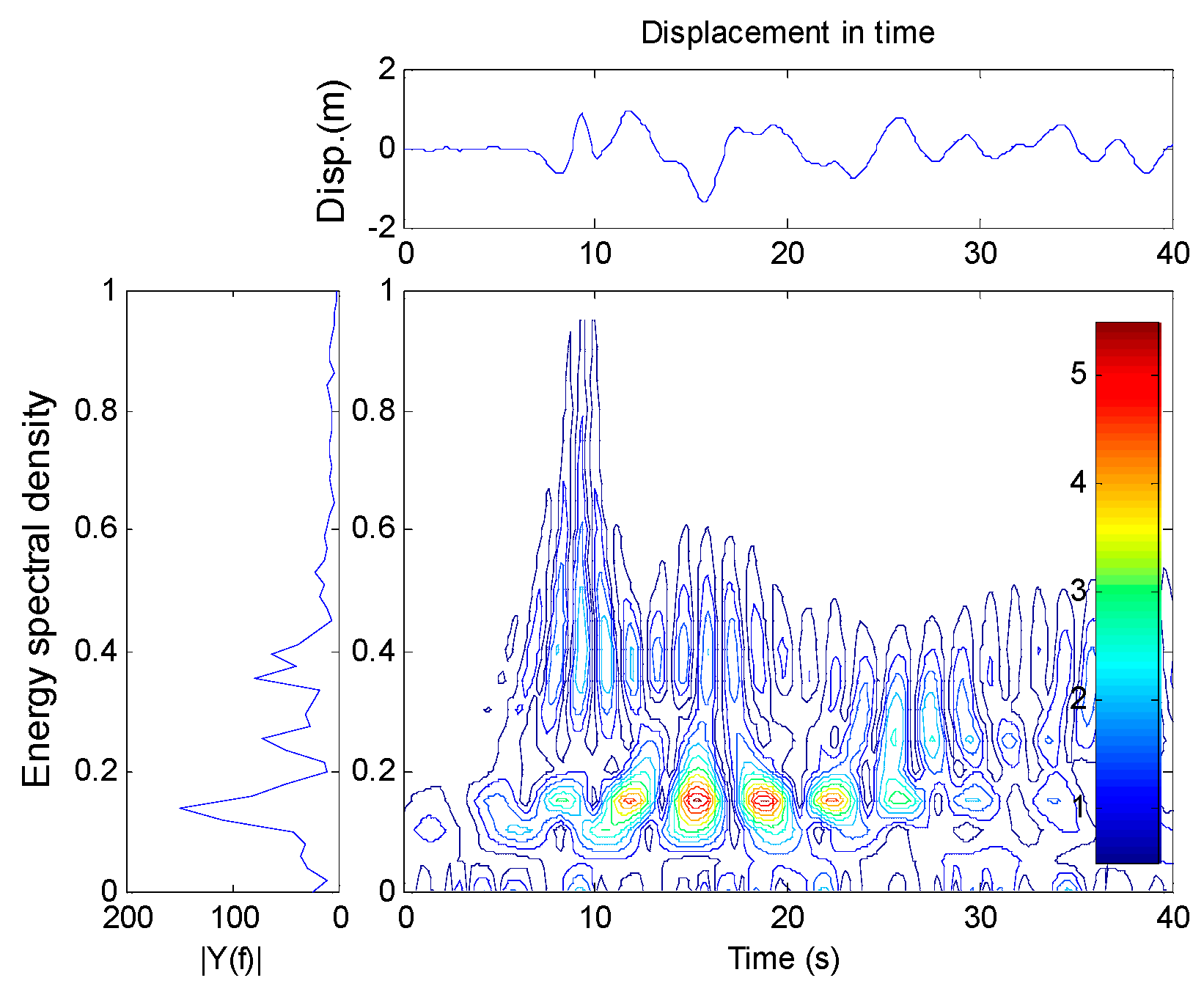
3. Seismic Response of the Super-Long-Span Suspension Bridge Exposed to Near/Far-Fault Earthquakes

Two far- and near-field ground motions were selected for this study. These were the El Centro (Imperial Valley earthquake in 1940, NS component at station El Centro, shown in Figure 6) and Chi-Chi earthquake records (Chi-Chi earthquake in 1999, EW component at station TCU052, shown in Figure 7), respectively. In the previous studies on seismic response analysis of long-span bridges under near-fault earthquake excitations, Chi-Chi earthquake records in 1999 were often selected and adopted [28,37]. Among the Chi-Chi earthquake records in 1999 from all stations, the EW component seismograms from station TCU052 and TCU068 contained the most typical near-field earthquake characteristics, such as velocity impulsive waveform and large slip displacement [38]. The peak ground acceleration (PGA) of each input ground motion was scaled to 400 gal and 800 gal, respectively. The frequency components of the selected earthquake records were not changed.
Based on the finite element model in Section 2, the seismic responses of the bridge exposed to the different earthquake excitations were calculated and analyzed. The maximum displacement and acceleration responses to the El Centro and Chi-Chi earthquakes are shown in Table 1 and Table 2.
When exposed to a far-fault earthquake, the transverse displacement at the top of the tower was 0.343 m and the lateral horizontal displacement angle was approximately 1/1122, indicating that the super-long-span suspension bridge was in an elastic state. When exposed to a near-fault earthquake, the horizontal displacement angle was approximately 1/295, indicating that a plastic state had appeared in the tower of the super-long-span suspension bridge.
To explain the reason why the seismic responses to the near-field earthquake were greater than those for a far-field earthquake, a time–frequency analysis of displacement at the tower top was performed, as shown in Figure 8 and Figure 9.
The results demonstrated that the main frequency of the tower exposed to a far-field earthquake was 0.35 Hz; when exposed to a near-field earthquake, the frequency was 0.15 Hz. Usually, the predominant period of a near-fault earthquake is longer than that of a far-fault earthquake, which was closer to the period of the super-long-span suspension bridge. Thus, exposure to a near-fault earthquake significantly increased the seismic response of the super-long-span suspension bridge.

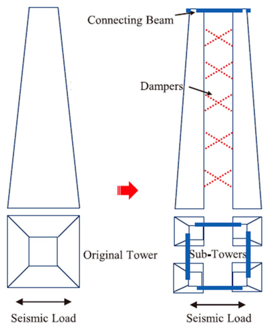
4. Lattice Composite Tower and Damping System

Based on the discussions in Section 3, this section introduces the lattice composite tower and damping system used to reduce the seismic responses of the super-long-span suspension bridge, especially when exposed to near-field earthquakes.

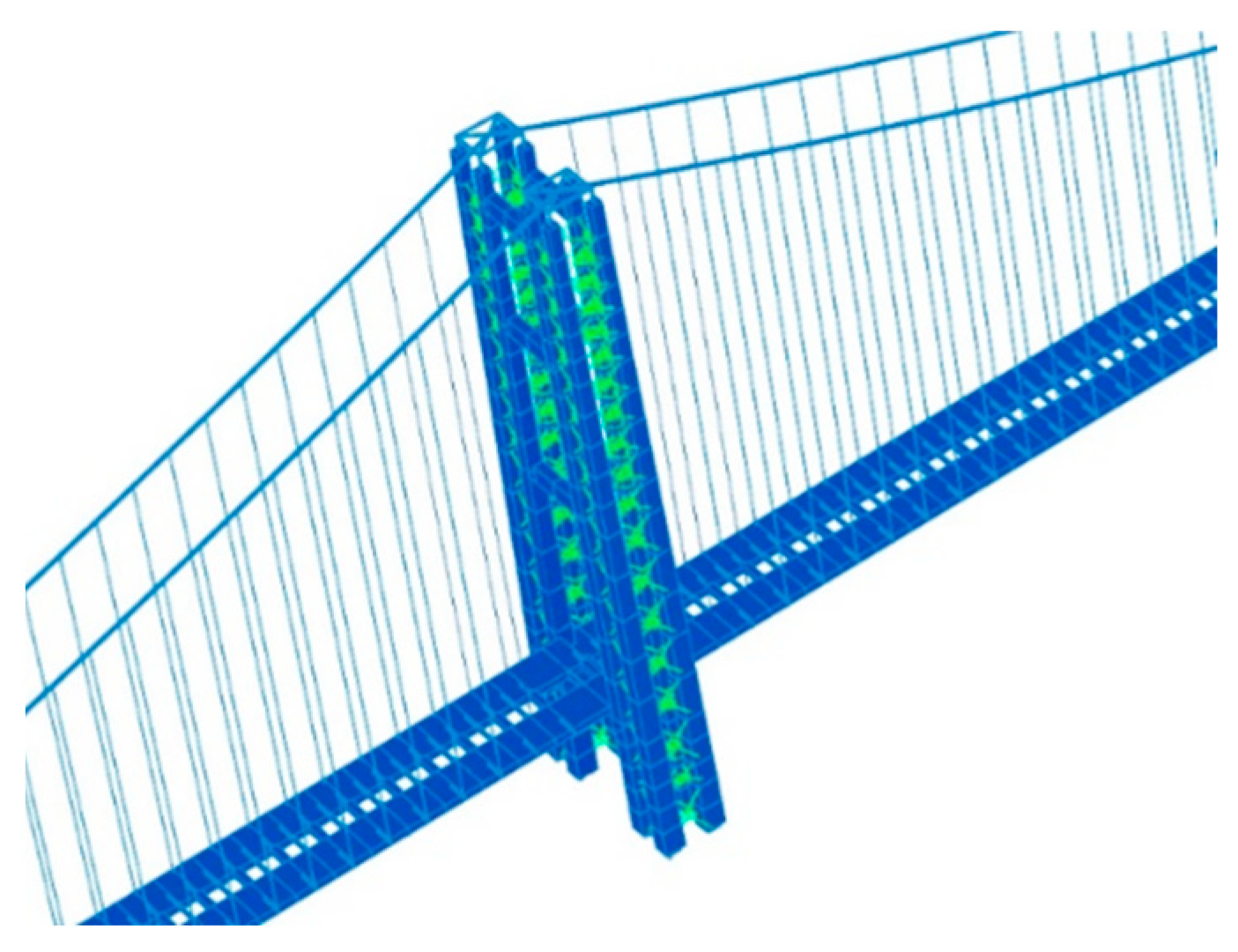
4.1. Finite Element Model of Lattice Composite Tower and Damping System

Traditional towers in a super-long-span suspension bridge usually have no space for the installation of energy dissipation devices due to their slenderness along the direction of the tower height. To allow space for the installation of energy dissipation devices, an alternative scheme with four separated sub-towers along the tower height as well as connecting beams at the tower top was proposed, as demonstrated in Figure 10. The term “lattice composite tower” refers to the whole of the four separated sub-towers connected through beams and dampers in a lattice form. A finite element model of a super-long-span suspension bridge with lattice composite towers and dampers was then established, as shown in Figure 11.
The frequencies of the original main tower, lattice composite tower and lattice composite tower with a friction damper were compared, as shown in Table 3. The frequency of the lattice composite tower was higher than that of the original main tower, indicating that the lattice composite tower effectively improved the lateral stiffness of the main tower in the super-long-span suspension bridge. The friction damper also enhanced the lateral stiffness of the main tower, resulting in a small increment in the frequencies.

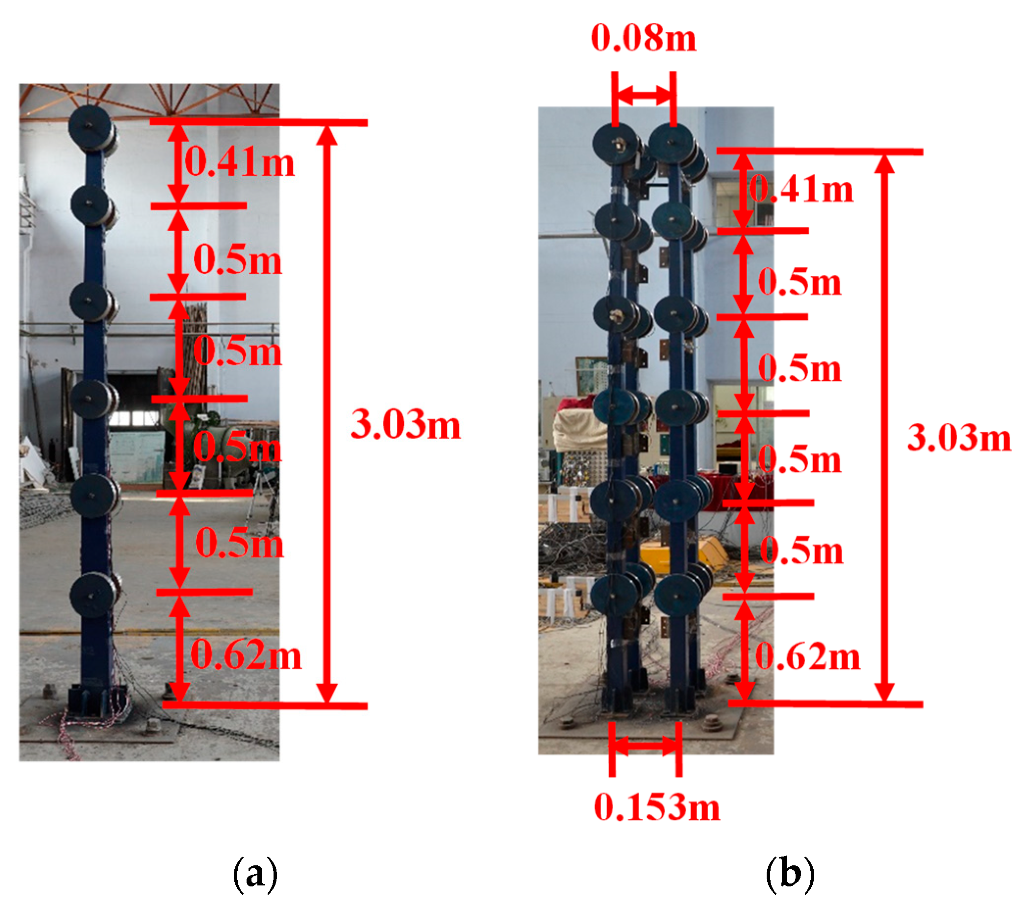
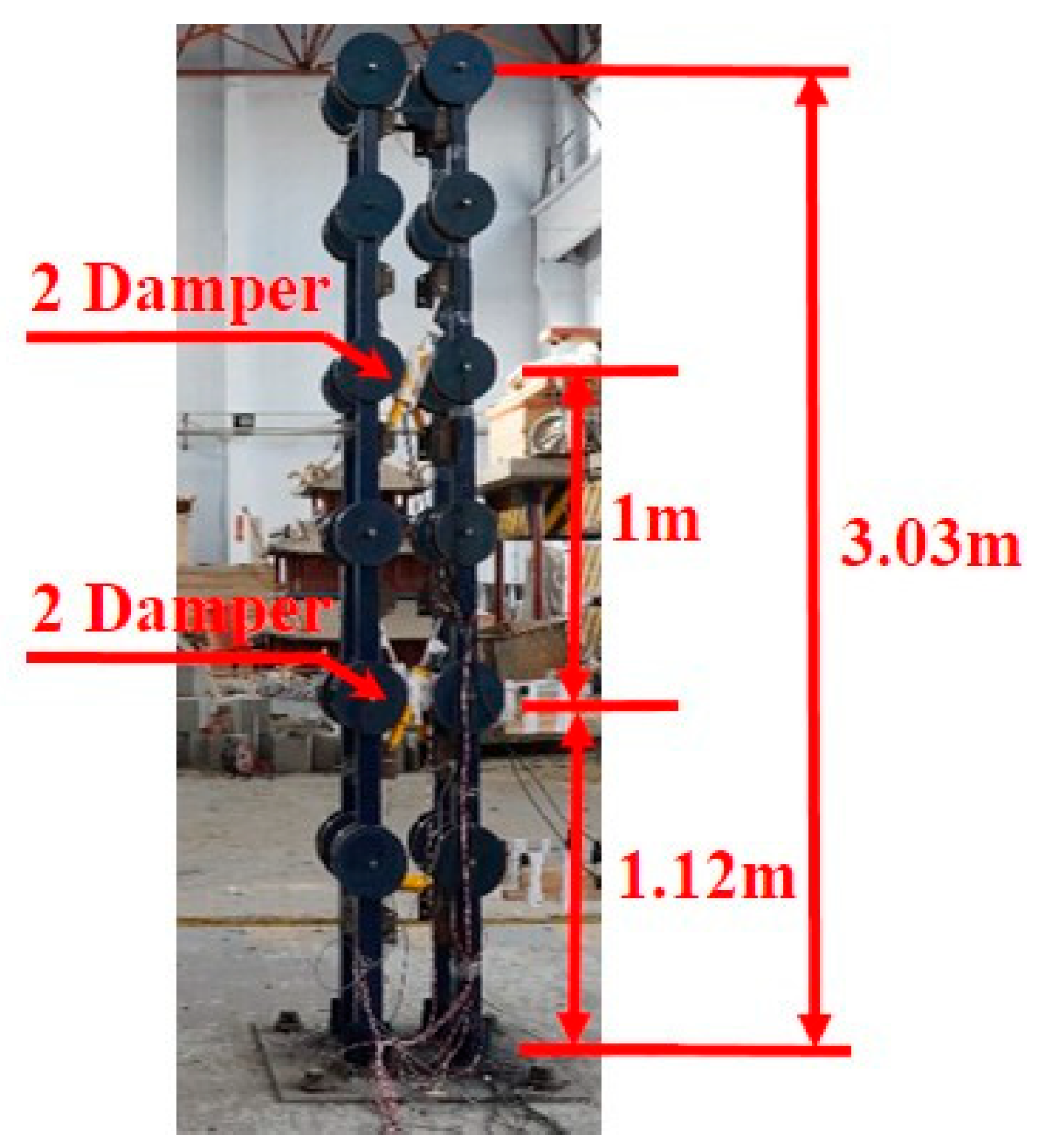
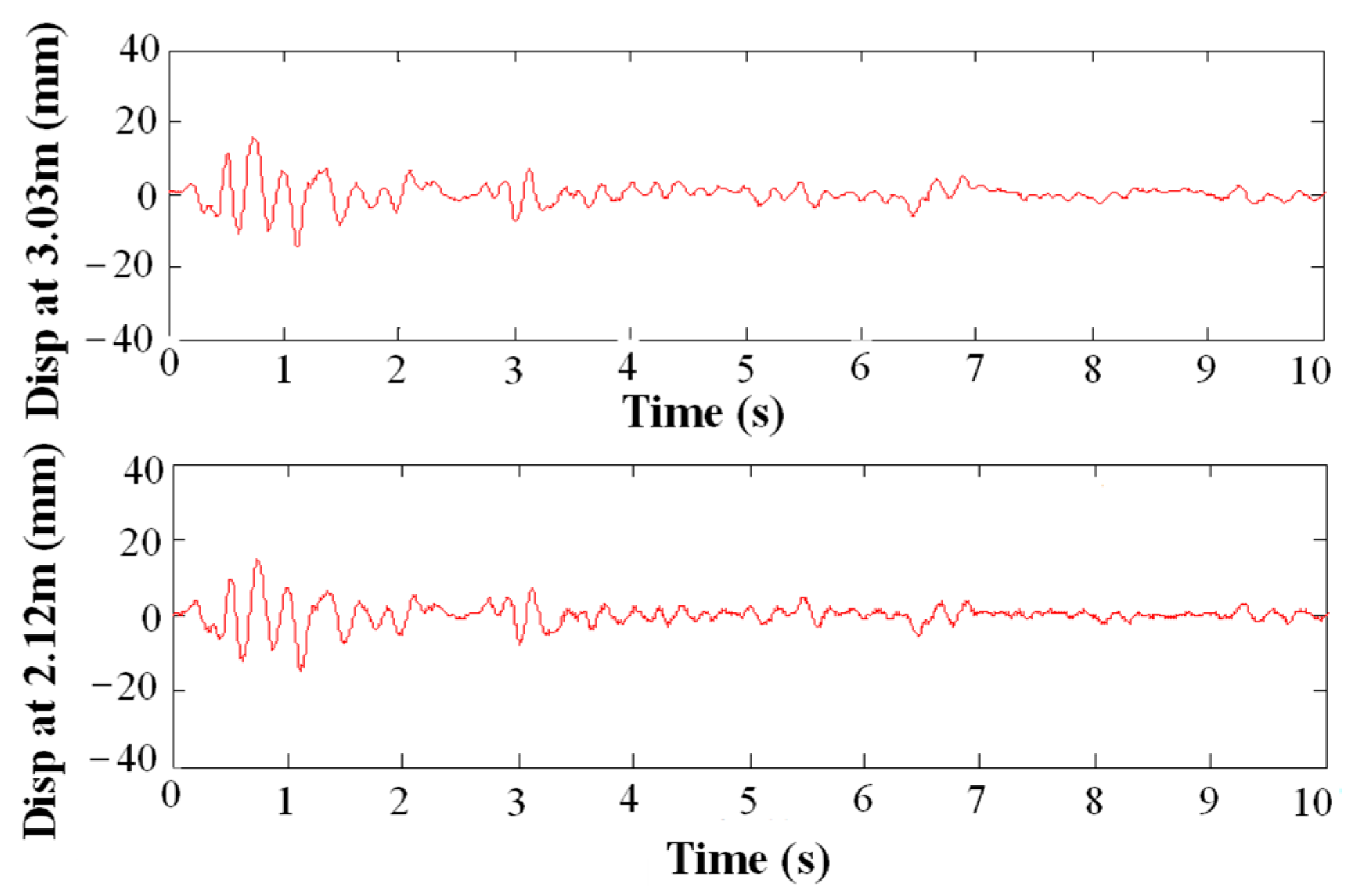
4.2. Experimental Verification of Scheme Feasibility

To verify the scheme feasibility of the proposed lattice composite tower and damping system, a shaking-table test of a scaled bridge tower model was then performed, as shown in Figure 12. Limited by shake-table size, the effect of the suspension cable and bridge deck system on the seismic response of bridge tower were not considered in this test. However, through the shake-table tests, a comparison of the dynamic characteristics as well as the seismic response between the original main tower and lattice composite tower could still be directly obtained. In this test, the original tower was manufactured using steel sheets with a thickness of 2.5 mm. The yielding strength was 345 MPa. The overall height of the main tower was 3.119 m. The cross-sections of the main tower were 153 mm × 153 mm and 80 mm × 80 mm at the bottom and top, respectively. Mass blocks of 50, 50, 40, 40, 40 and 50 kg were located at heights of 0.62, 1.12, 1.62, 2.12, 2.62 and 3.03 m, respectively. For the lattice composite tower scheme, the height of the four separate sub-towers was identical to the original tower. The cross-section of each sub-tower was 81 mm × 81 mm at the bottom. At the top, the cross-section was changed to 50 mm × 50 mm. These four sub-towers were located at the four corners of a square, with a cross-section of 220 mm × 220 mm. The mass blocks were equably distributed at the same height in the four sub-towers. The sub-towers were connected together with four connecting beams at the top.
Typical earthquake records were chosen to evaluate the seismic performance of the lattice composite tower, including the El Centro earthquake with a PGA of 580 gal. The seismic response at the tower top is shown in Figure 13. The results indicated that the lattice composite tower markedly decreased the displacement response at the tower top and improved the seismic performance of the super-long-span suspension bridge. These seismic reduction effects of the tower top displacement agreed well with the results in reference [15]. In addition, the control effect of the tower top displacement by viscous damping system could reach over 46%, which is close to the results in reference [31].

5. Damping System

A damping system was established by adding different types of dampers and arrangement schemes between the adjacent sub-towers. In this section, the influences of different damping systems on the seismic responses of the main tower are discussed, including different damper types, damper arrangements and design parameters.

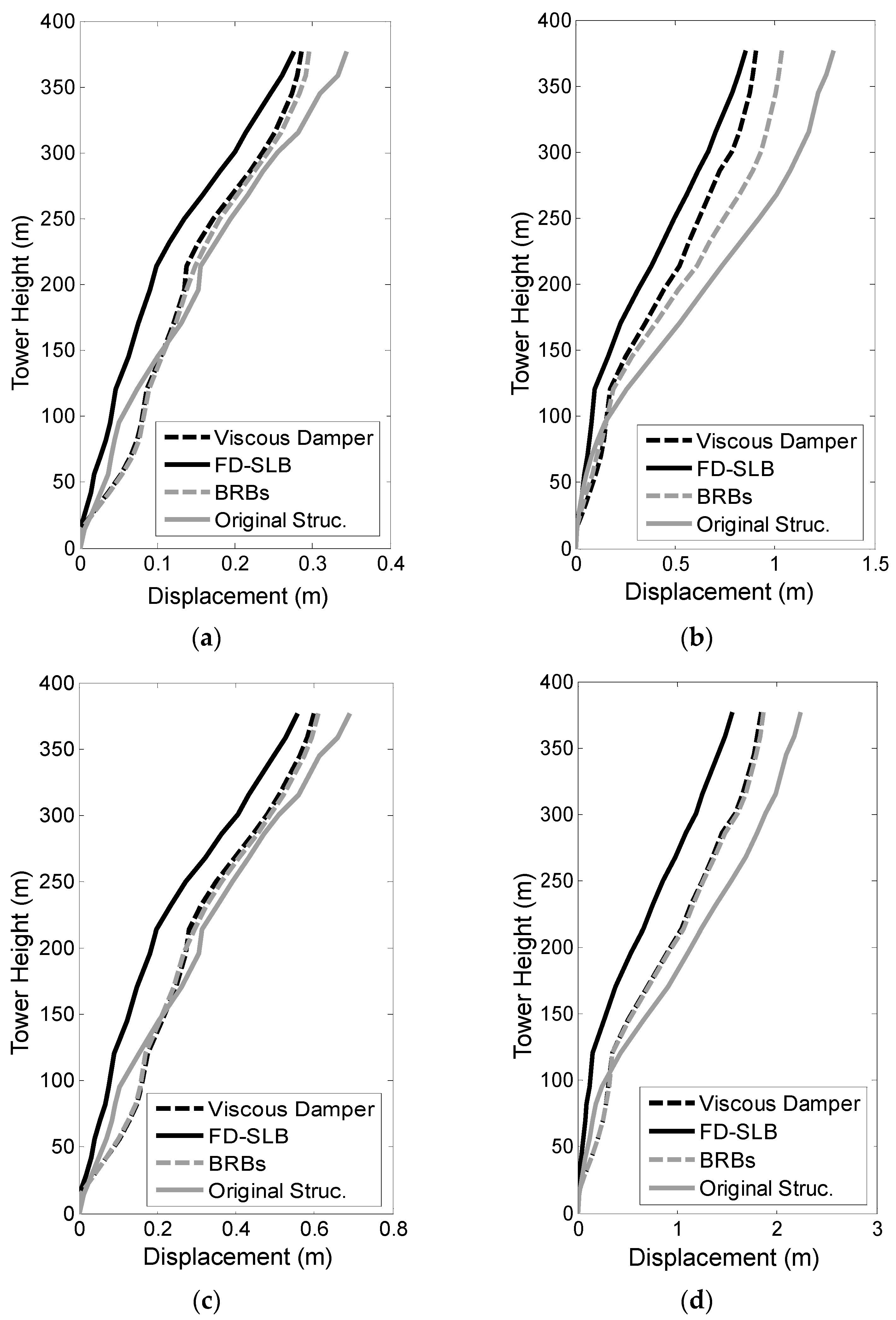
5.1. Influence of Damper Types on Seismic Responses

The influence of the damper type on the seismic response of a super-long-span suspension bridge with a lattice composite tower was analyzed. The damper types were a viscous damper (VD), a buckling-restrained brace (BRB) and a friction damper combined with a shear-link beam (FD-SLB). The parameters of the dampers were as follows. The viscous damper had a damping coefficient of 1000 kN·(m/s)−0.5 and a velocity index of 0.5. The buckling-restrained brace had a yield force of 1500 kN and a bi-linear constitutive relationship, in which the second stiffness coefficients were 0.02, 0.06 and 0.10, respectively. The friction damper had sliding forces of 1000 kN and 1500 kN, respectively, and the shear-link beam had a shear stiffness of 5 × 10⁴ kN/m.
As shown in Figure 14, 72 dampers were installed among the sub-towers along the transverse and longitudinal directions.
Seismic responses from different types of dampers exposed to far-fault and near-fault earthquakes were calculated and compared. The displacement and the acceleration responses along the height of the tower are shown in Figure 15. It is noted that the tower response of the suspension bridge under the near-fault ground motion was larger than that of the far-fault ground motion, and the results agree well with the earthquake-induced response tendency of long-span bridges in the literature [27,28].
The results demonstrated that the friction damper combined with the shear-link beam (FD-SLB) performed better than the other two types of dampers (VD and BRB) at reducing seismic responses. When using El Centro earthquake excitation data, the control effects of all types of dampers on the displacement of the tower were similar because the displacement responses of the tower were small and the tower was mostly in an elastic state. When using Chi-Chi earthquake excitation data, the displacement responses of the tower markedly increased compared with those exposed to El Centro earthquake data, which agreed with the results in reference [28]. The displacement of the dampers significantly increased; thus, the energy dissipation ratio of the damping system also improved. This indicated that FD-SLB could significantly decrease the seismic response of super-long-span suspension bridges, especially those exposed to near-fault ground motions, as it satisfied the energy dissipation requirements more effectively.
To verify the accuracy of the above analyses, scaled shaking-table tests of the lattice composite tower with viscous dampers were performed. Four dampers were installed in a bottom-middle distribution, as shown in Figure 16. The design parameters and test scheme were the same as those listed in Section 4.2. The velocity power index and the viscous coefficient of the viscous damper were 0.9 and 58 N s/mm, respectively. The mechanical properties of the viscous dampers can be found in reference [15].
The displacement history along the height of the lattice composite tower used in the test is provided in Figure 17. These results were compared with the displacement responses of the original main tower. The displacement damping rate at 2/3 the height of the tower was 60.8% in the test and 54.5% in the FEA results. The displacement control effect at the tower top was 52.1% in the test and 48.3% in the FEA results. The test results demonstrated the accuracy of the finite element model and analysis method. It was noted that the bottom-middle damper arrangement scheme could significantly decrease the seismic response of the super-long-span suspension bridge.

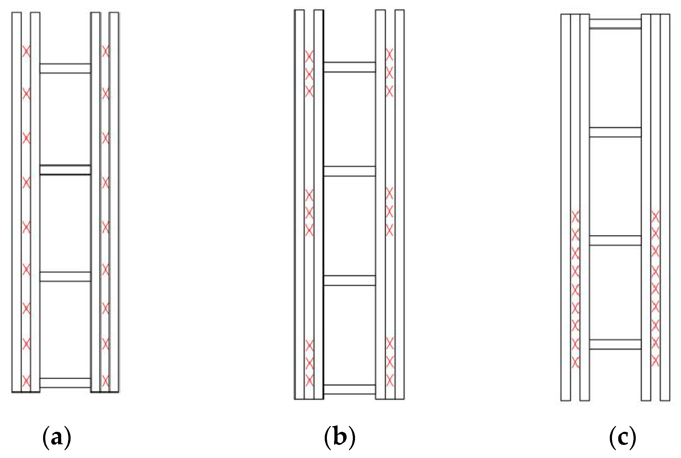
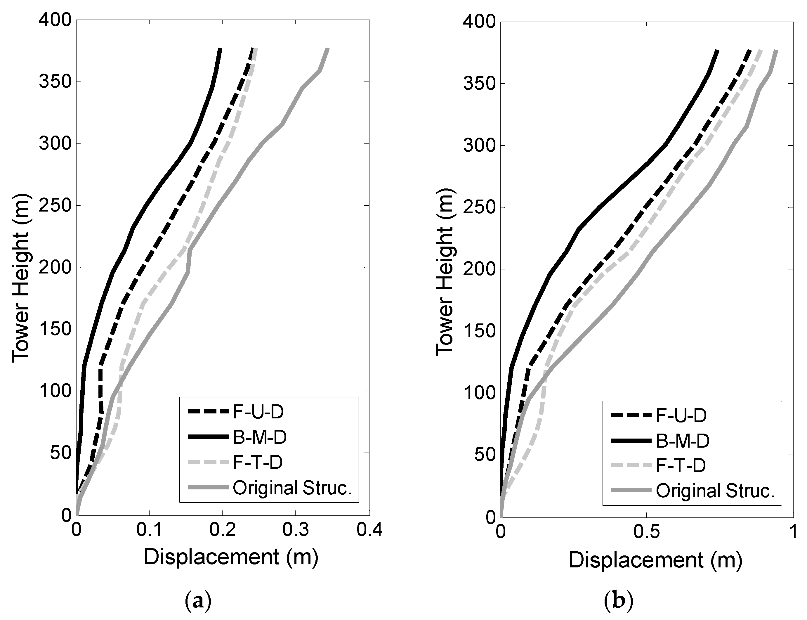
5.2. Influence of Damper Arrangement Schemes on the Seismic Responses

In the damping systems of super-long-span suspension bridges, the distribution of additional stiffness and additional damping can be adjusted through damper arrangement schemes. Hence, it is important to study and optimize damper arrangements to improve the seismic performance of a whole system exposed to strong earthquakes. In this paper, three types of damper arrangement scheme were proposed; full-uniform distribution (FUD), full-trilaminar distribution (FTD) and bottom-middle distribution (BMD), as shown in Figure 18. Based on the results of Section 4.2, a friction damper combined with a shear-link beam (FD-LSB) was used for this contrastive analysis. The displacement responses along the height of the tower with different damper arrangement schemes are shown in Figure 19.
The damper arrangement schemes clearly affected the seismic responses. The BMD scheme exposed to both far-fault and near-fault earthquakes performed the best among the three damper arrangement schemes. This was because the dampers were mainly installed in the bottom-middle of the tower, where the shear force and bending movement were larger than those of the other locations in the tower. The relative displacement in the bottom and middle parts of the adjacent sub-towers was also larger than the top.

5.3. Influence of Damper Parameters on the Seismic Responses

To improve the seismic performance of super-long-span suspension bridges, the influence of the damper parameters on the seismic response reduction was parametrically analyzed. Based on the discussions summarized in the last two sections, a friction damper combined with a shear-link beam (FD-SLB) damper and a BMD damper arrangement scheme were adopted.
The initial sliding force of the friction damper was selected as one optimized parameter. The initial sliding forces of the friction damper were set to 1000 kN and 1500 kN, respectively. The displacement responses along the height of tower with different initial sliding forces of the friction damper are shown in Figure 20.
As shown in Figure 20, the displacement at the tower top decreased with a decline in the initial sliding force of FD-SLB when exposed to a far-fault earthquake. In the results of the finite element model, damper sliding did not occur at an initial sliding force of 1500 kN, but it did occur at an initial sliding force of 1000 kN. Hence, FD-SLB with an initial sliding force of 1000 kN worked with the energy dissipation to decrease the seismic response. In comparison, a larger displacement caused damper sliding when exposed to a near-fault earthquake, even though the initial force was only 1000 kN. FD-SLB with an initial sliding force of 1500 kN had larger energy dissipation, which resulted in smaller displacement responses.
Thus, dampers should be designed with a reasonable initial sliding force to ensure damper sliding during the whole process of earthquake excitation. The initial sliding force could be increased when super-long-span suspension bridges are located close to near-fault areas.

6. Conclusions

To improve the seismic performance of super-long-span suspension bridges, comparative studies were performed. These focused on the seismic responses of an original main tower system and a lattice composite tower system exposed to far-fault and near-fault earthquakes using a finite element analysis and shaking-table tests. The influence of the damping system on the reduction effect of the seismic responses was analyzed. This included the damper type, damper arrangement scheme and design parameters. The primary conclusions were as follows:
  • A lattice composite tower and damping system could increase the lateral stiffness of the main tower in a super-long-span suspension bridge. An optimal damping system could enhance the energy dissipation ability.
  • A lattice composite tower and damping system could significantly reduce seismic responses and improve seismic performance in super-long-span suspension bridges. In our analysis, the displacement control effect at the tower top for the lattice composite tower and viscous damping system reached as much as 50% when using El Centro earthquake excitation data.
  • Comparative analyses indicated that a friction damper combined with a shear-link beam (FD-SLB damper type) and a bottom-middle distribution scheme (BMD damper arrangement scheme) were the most effective when exposed to seismic excitations. The FD-SLB should be designed with a reasonable initial sliding force to ensure damper sliding is effective when exposed to an earthquake. A variable stiffness friction damper may be a better choice for near-fault earthquake excitations, and should be systematically investigated in future.

Author Contributions

Software, P.Z.; Writing—original draft and data curation, Y.Z.; Writing—review & editing, Y.W.; Project administration, S.L. All authors have read and agreed to the published version of the manuscript.

Funding

The authors greatly appreciate the financial support from the Shandong Provincial Natural Foundation, with Grant No. ZR2020ME247, and the Foundation of Key Laboratory of Large Structure Health Monitoring and Control in Hebei Province (KLLSHMC2105).

Institutional Review Board Statement

Not applicable.

Informed Consent Statement

Not applicable.

Data Availability Statement

Not applicable.

Conflicts of Interest

The authors declare no conflict of interest.

References

  1. Wang, D.; Ye, J.; Wang, B.; Wahab, M.A. Review on the service safety assessment of main cable of long span multi-tower suspension bridge. Appl. Sci. 2021, 11, 5920. [Google Scholar] [CrossRef]
  2. Chong, H.; Wang, D.; Wang, B.; Shen, X.; Wahab, M.A. Gradual deterioration behavior of the load-bearing strength of main cable wires in a suspension bridge. Appl. Sci. 2023, 13, 129. [Google Scholar] [CrossRef]
  3. Hu, S.; Yang, H.; Luo, S.; Wu, J. Overall design of puqian bridge in Hainan. Bridge Constr. 2016, 46, 94–99. [Google Scholar]
  4. Calvi, G.M.; Sullivan, T.J.; Villani, A. Conceptual Seismic Design of Cable-Stayed Bridges. J. Earthq. Eng. 2010, 14, 1139–1171. [Google Scholar] [CrossRef]
  5. Li, J.; Peng, T.; Xu, Y. Damage investigation of girder bridges under the Wenchuan earthquake and corresponding seismic design recommendations. Earthq. Eng. Eng. Vib. 2008, 7, 337–344. [Google Scholar] [CrossRef]
  6. Kawashima, K.; Unjoh, S.; Hoshikuma, J.-I.; Kosa, K. Damage of Bridges due to the 2010 Maule, Chile, Earthquake. J. Earthq. Eng. 2011, 15, 1036–1068. [Google Scholar] [CrossRef]
  7. Buckle, I.; Yen, W.; Marsh, L.; Monzon, E. Implications of bridge performance during Great East Japan Earthquake for US seismic design practice. In Proceedings of the International Symposium on Engineering Lessons Learned from the 2011 Great East Japan Earthquake, Tokyo, Japan, 1–4 March 2012; pp. 1363–1374. [Google Scholar]
  8. Puri, L.; Sharma, G.; Kaur, T. Modeling and development of eddy current damper for aerospace applications. Int. J. Dyn. Control 2023. [Google Scholar] [CrossRef]
  9. Deng, H.; Gao, Y.; Hu, R.; Zhao, S.; Han, G.; Lian, X.; Ma, M.; Zhong, X. Self-sensing automotive magnetorheological dampers for low frequency vibration. Smart Mater. Struct. 2021, 30, 115015. [Google Scholar] [CrossRef]
  10. Xu, L.; Gao, Q.; Zheng, J.; Ding, C.; Liu, K. Seismic response mitigation of a long-span tower bridge with two types of constraint system. Adv. Civ. Eng. 2020, 2020, 8846467. [Google Scholar] [CrossRef]
  11. Lu, L. Application of buckling-restrained braces in the seismic control of suspension bridges. Earthq. Eng. Eng. Vib. 2022, 21, 543–557. [Google Scholar] [CrossRef]
  12. Ruiz, R.; Taflanidis, A.; Lopez-Garcia, D. Characterization and design of tuned liquid dampers with floating roof considering arbi-trary tank cross-sections. J. Sound Vib. 2016, 368, 36–54. [Google Scholar] [CrossRef]
  13. Bitaraf, M.; Ozbulut, O.E.; Hurlebaus, S.; Barroso, L. Application of semi-active control strategies for seismic protection of buildings with MR dampers. Eng. Struct. 2010, 32, 3040–3047. [Google Scholar] [CrossRef]
  14. Zhang, Z.; Staino, A.; Basu, B.; Nielsen, S.R. Performance evaluation of full-scale tuned liquid dampers (TLDs) for vibration control of large wind turbines using real-time hybrid testing. Eng. Struct. 2016, 126, 417–431. [Google Scholar] [CrossRef]
  15. Zhou, P.; Liu, M.; Li, S.; Li, H.; Song, G. Experimental study on seismic control of towers in cable-supported bridges by incorporating fluid viscous dampers between sub-towers. Adv. Struct. Eng. 2020, 23, 2086–2096. [Google Scholar] [CrossRef]
  16. Pan, S.; Wang, J.; Fan, S.; Tian, K.; Zhu, W. Comparative analysis of buffer and damper positions for increasing the seismic per-formance of suspension bridge. Buildings 2022, 13, 81. [Google Scholar] [CrossRef]
  17. Liu, Z.; Chen, L.; Sun, L. Damping of long-span suspension bridges with damped outriggers. In Proceedings of the International Association for Bridge and Structural Engineering Congress Nanjing, Nanjing, China, 21–23 September 2022; pp. 1856–1864. [Google Scholar]
  18. Ren, L.; Fang, Z.; Wang, K. Design and behavior of super-long span cable-stayed bridge with CFRP cables and UHPC members. Compos. Part B Eng. 2019, 164, 72–81. [Google Scholar] [CrossRef]
  19. Meiz, K.; Sun, S.; Jin, G.; Sun, Y. Static and dynamic mechanical properties of long-span cable-stayed bridges using CFRP ca-bles. Adv. Civ. Eng. 2017, 2017, 6198296. [Google Scholar]
  20. Jia, H.; Yang, J.; Zheng, S.; Zhao, C. A review on aseismic bridges crossing fault rupture regions. J. Southwest Jiaotong Univ. 2021, 56, 1075–1093. (In Chinese) [Google Scholar]
  21. Takewaki, I.; Moustafa, A.; Fujita, K. Improving the Earthquake Resilience of Buildings; Springer: London, UK, 2013. [Google Scholar] [CrossRef]
  22. Mukhopadhyay, S.; Gupta, V. Directivity pulses in near-fault earthquake I: Identification, extraction and modeling. Soil Dyn. Earthq. Eng. 2013, 50, 1–15. [Google Scholar] [CrossRef]
  23. Donahue, J.L.; Abrahamson, N.A. Simulation-Based Hanging Wall Effects. Earthq. Spectra 2014, 30, 1269–1284. [Google Scholar] [CrossRef]
  24. Yang, D.; Zhou, J. A stochastic model and synthesis for near-fault impulsive earthquake. Earthq. Eng. Struct. Dyn. 2015, 44, 243–264. [Google Scholar] [CrossRef]
  25. Chen, X.; Liu, Y.; Zhou, B.; Yang, D. Seismic response analysis of intake tower structure under near-fault earthquake with forward-directivity and fling-step effects. Soil Dyn. Earthq. Eng. 2020, 132, 106098. [Google Scholar] [CrossRef]
  26. Liu, T.; Luan, Y.; Zhong, W. A numerical approach for modeling near-fault ground motion and its application in the 1994 Northridge earthquake. Soil Dyn. Earthq. Eng. 2012, 34, 52–61. [Google Scholar] [CrossRef]
  27. Zhang, C.; Fu, G.; Lai, Z.; Du, X.; Wang, P.; Dong, H.; Jia, H. Shake table test of long span cable-stayed bridge subjected to near-fault ground motions considering velocity pulse effect and non-uniform excitation. Appl. Sci. 2020, 10, 6969. [Google Scholar] [CrossRef]
  28. Xie, W.; Sun, L. Experimental and numerical investigations on transverse seismic responses of soil-cable-stayed-bridge system subjected to transverse near-fault ground motions. Eng. Struct. 2021, 226, 111361. [Google Scholar] [CrossRef]
  29. Mao, J.; Wang, H.; Xu, Y.; Li, H. Deformation monitoring and analysis of a long-span cable-stayed bridge during strong ty-phoons. Adv. Bridge Eng. 2020, 1, 8. [Google Scholar] [CrossRef]
  30. Sun, L.; Xie, W. Full-model shaking table tests of seismic behavior of a super-long-span cable-stayed bridge with pile founda-tions. J. Bridge Eng. 2019, 24, 04019102. [Google Scholar] [CrossRef]
  31. Xu, L.; Zhang, H.; Gao, J.; Zhang, C. Longitudinal seismic responses of a cable-stayed bridge based on shaking table tests of a half-bridge scale model. Adv. Struct. Eng. 2019, 22, 81–93. [Google Scholar] [CrossRef]
  32. Wang, X.; Wang, L.; Wang, H.; Ning, Y.; Huang, K.; Wang, W. Performance Evaluation of a Long-Span Cable-Stayed Bridge Using Non-Destructive Field Loading Tests. Appl. Sci. 2022, 12, 2367. [Google Scholar] [CrossRef]
  33. Lin, K.; Xie, L.; Lu, X.; Ye, L. Earthquake-induced collapse simulation of a super long span cable-stayed bridge based on an open source FE program. Int. Assoc. Bridge Struct. Eng. Symp. Rep. 2015, 105, 1–8. [Google Scholar]
  34. Ge, Y.; Zhao, L.; Cao, J. Case study of vortex-induced vibration and mitigation mechanism for a long-span suspension bridge. J. Wind. Eng. Ind. Aerodyn. 2022, 220, 104866. [Google Scholar] [CrossRef]
  35. Dionysius, M.; Yozo, F. Seismic response of a suspension bridge: Insights from long-term full-scale seismic monitoring system. Struct. Control Health Monit. 2018, 25, 2252. [Google Scholar]
  36. Aksel, F.; Ole, Ø.; Anders, R. Long-term monitoring of wind field characteristics and dynamic response of a long-span suspen-sion bridge in complex terrain. Eng. Struct. 2017, 147, 269–284. [Google Scholar]
  37. Zheng, S.-X.; Jia, H.-Y.; Zhao, C.-H.; Qu, H.-L.; Shi, X.-L. Seismic response analysis of long-span and asymmetrical suspension bridges subjected to near-fault ground motion. Eng. Fail. Anal. 2020, 115, 104615. [Google Scholar] [CrossRef]
  38. Ma, K.F.; Brodsky, E.E.; Mori, J.; Ji, C.; Song, T.R.A.; Kanamori, H. Evidence for fault lubrication during the 1999 Chi-Chi, Taiwan, earthquake (Mw7.6). Geophys. Res. Lett. 2003, 30, 1244. [Google Scholar] [CrossRef]
Figure 1. Layout of the super-long-span suspension bridge.
Applsci 13 09387 g001
Figure 2. The details of lattice composite towers.
Applsci 13 09387 g002
Figure 3. Finite element model of the super-long-span suspension bridge.
Applsci 13 09387 g003
Figure 4. Frequency distribution diagram.
Applsci 13 09387 g004
Figure 5. Mode shapes of the finite element model: (a) first vibration mode (0.055 Hz); (b) second vibration mode (0.089 Hz).
Applsci 13 09387 g005
Figure 6. Imperial Valley earthquake record (station El Centro, NS), May 1940.
Applsci 13 09387 g006
Figure 7. Chi-Chi earthquake record (station TCU052, EW), September 1999.
Applsci 13 09387 g007
Figure 8. Time–frequency analysis of tower top displacement using El Centro earthquake data.
Applsci 13 09387 g008
Figure 9. Time–frequency analysis of tower top displacement using Chi-Chi earthquake data.
Applsci 13 09387 g009
Figure 10. FEM of a super-long-span suspension bridge with lattice composite towers.
Applsci 13 09387 g010
Figure 11. Detail of lattice composite tower.
Applsci 13 09387 g011
Figure 12. Test specimen of original main tower and lattice composite tower: (a) original main tower; (b) lattice composite tower.
Applsci 13 09387 g012
Figure 13. Comparison of seismic responses at the tower top between original main tower and lattice composite tower: (a) acceleration response; (b) displacement response.
Applsci 13 09387 g013
Figure 14. Damper distribution in the sub-towers.
Applsci 13 09387 g014
Figure 15. Displacement along the height of the tower with different types of dampers: (a) El Centro, PGA = 400 gal; (b) Chi-Chi, PGA = 400 gal; (c) El Centro, PGA = 800 gal; (d) Chi-Chi, PGA = 800 gal.
Applsci 13 09387 g015
Figure 16. Test specimen of a lattice composite tower with viscous dampers.
Applsci 13 09387 g016
Figure 17. Displacement response of the lattice composite tower with viscous dampers.
Applsci 13 09387 g017
Figure 18. Classical types of damper arrangements: (a) full-uniform distribution; (b) full-trilaminar distribution; (c) bottom-middle distribution.
Applsci 13 09387 g018
Figure 19. Displacement along the height of the tower with different damper arrangement schemes: (a) El Centro, PGA = 400 gal; (b) Chi-Chi, PGA = 400 gal.
Applsci 13 09387 g019
Figure 20. Displacement along the height of the tower with different initial sliding forces of friction damper: (a) El Centro, PGA = 400 gal; (b) Chi-Chi, PGA = 400 gal.
Applsci 13 09387 g020
Table 1. Displacement and acceleration responses to earthquake excitation (PGA = 400 gal).
LocationEl Centro Ground MotionChi-Chi Ground Motion
Displacement (m)Acceleration (m/s2)Displacement (m)Acceleration (m/s2)
Top of tower0.3436.0061.2979.365
Middle of tower0.1295.6370.5686.697
Mid-span of main cable0.5147.3495.52616.050
Mid-span of bridge deck0.3653.4495.9817.283
Table 2. Displacement and acceleration responses to earthquake excitation (PGA = 800 gal).
LocationEl Centro Ground MotionChi-Chi Ground Motion
Displacement (m)Acceleration (m/s2)Displacement (m)Acceleration (m/s2)
Top of tower0.6559.9072.50219.119
Middle of tower0.2328.2561.29311.392
Mid-span of main cable0.80714.24811.68126.785
Mid-span of bridge deck0.8067.19011.59110.361
Table 3. Frequencies of the super-long-span suspension bridge.
ModelSingle Tower
(Hz)
Lattice Composite Tower
(Hz)
Lattice Composite Tower with
Friction Damper
(Hz)
10.0550.0560.057
20.0890.0920.094
30.1000.1020.102
40.1040.1050.106
50.1260.1320.134
60.1340.1460.149
70.1450.1470.149
80.1460.1510.153
90.1500.1530.154
100.1560.1570.158
Disclaimer/Publisher’s Note: The statements, opinions and data contained in all publications are solely those of the individual author(s) and contributor(s) and not of MDPI and/or the editor(s). MDPI and/or the editor(s) disclaim responsibility for any injury to people or property resulting from any ideas, methods, instructions or products referred to in the content.

