Abstract
Owing to the advantages of accelerated construction, reduced traffic disturbance, and enhanced quality control, precast segmental two-column bents are extensively utilized in urban and highway bridges, particularly in areas of low-to-medium seismicity. However, the application of this technique in high-seismicity regions is limited owing to insufficient knowledge about the seismic performance of such precast bents. To address this, the present study investigates the seismic performance of precast segmental two-column bents, focusing on the connection of “grouted splice sleeves and grouted central tenon”, namely the proposed GSS-GCT connection. For this purpose, three large-scale two-column bent specimens were fabricated and subjected to quasi-static cyclic tests: one cast-in-place bent, one precast two-column bent with conventional grouted splice sleeves, and another with the GSS-GCT connection. The benefits of the GSS-GCT connection under high seismic activities were demonstrated regarding lateral load-carrying capacity, displacement ductility, energy dissipation capacity, and residual displacement. Moreover, five levels of damage states were qualitatively and quantitatively divided based on experimental observation, which can be evaluated with lateral displacements. Furthermore, seismic assessments of the two-column bents were obtained using the capacity spectrum method. The proposed GSS-GCT connection could significantly improve the seismic performance of precast segmental two-column bents under high-level earthquakes.
1. Introduction
As a part of Accelerated Bridge Construction (ABC) techniques, using a precast bridge pier can improve bridge construction in terms of rapidity, quality, and environmental impact [1,2]. Currently, precast segmental piers are extensively utilized in urban and highway bridges, especially in areas of low-to-medium seismicity [3,4]. However, the application of this technique in high-seismicity regions is limited, primarily due to its insufficient energy dissipation capacity [5]. It is acknowledged that the connections between precast segments are critical for creating structural continuity, thus impacting the seismic behavior of the structure during extreme ground motion. To this end, various connection types between segments are applied to strengthen the precast pier’s seismic performances, such as grouted splice sleeves [6,7,8,9], grouting corrugated pipes [10,11,12], grouted pockets [13,14], grouted ducts [15], and post-tensioned tendons [16,17].
Among them, grouted splice sleeves (GSS) are particularly notable and extensively employed, attributed to their generous construction tolerance and dependable one-to-one energy-dissipating rebar connections [18]. Significant experimental research focusing on precast segmental bridge piers employing grouted sleeve connections has been conducted within the academic community. Ameli et al. [19] conducted experimental research on three octagonal pier specimens. The results revealed that embedding the grouted splice sleeves within the column, as opposed to the footing, leads to superior ductility and energy dissipation capacity of the pier. Ou et al. [20] conducted quasi-static tests on precast segmental piers with a square cross-sectional dimension of 600 mm × 600 mm. The results indicate a significant influence of the axial compression ratio on the hysteresis behavior and ductility of the specimens. While precast segmental piers manifest a comparable lateral load-carrying capacity to their cast-in-place counterparts, a minor compromise in ductility is observed. Haber et al. [21] conducted experimental research on a cast-in-place circular column and a circular column connected with grouted splice sleeves. Owing to the large cross-sectional area of the grouted splice sleeves in the column section, the stiffness at the bottom of the column is more significant than that in regular precast piers, leading to a relocation of the plastic hinge in the pier column. The displacement ductility of a pier column has been significantly improved.
However, although the GSS connection provides an effective interconnection of rebar for precast segmental bridge piers, the concrete at the joint remains non-continuous, setting these piers apart from cast-in-place piers in terms of the overall integrity and seismic performance [22]. Extensive research indicates that precast segmental piers connected with a GSS connection exhibit inferior strength and displacement ductility compared to their cast-in-place counterparts [23,24,25,26]. Furthermore, the premature failure of the slurry layer at the joints, coupled with the inferior ductility of the GSS connectors, resulted in a reduced energy dissipation capacity and displacement ductility for the precast segmental piers [27,28]. Therefore, it is necessary to make appropriate improvements to the GSS connection method to enhance the seismic performance of precast segmental piers, making them suitable for use in areas with high seismic intensity.
Moreover, current research on precast segmental bridge piers mainly focuses on single-column pier systems, while studies on frame-style two-column bents are less common [29]. Compared with precast segmental single-column piers, precast two-column bents are more complex. Single-column piers can be simplified into an equivalent single degree of freedom (SDOF) system under seismic activities, with the plastic hinge at the bottom of the pier column. However, the frame-style two-column bents exhibit different seismic performances. Potential plastic hinges are located at both the top and bottom of the columns, presenting issues such as internal force redistribution [30]. In practical applications, frame-style two-column bents serve as a prevalent design choice for bridge piers. With the increasing demand for broader bridge widths to accommodate more traffic lanes, the application of the two-column pier system is likely to become more widespread [31].
Consequently, it is imperative to conduct systematic research on the seismic performance of precast segmental two-column bents. Khaleghi et al. [32] proposed a precast bridge bent structure where the column was connected to the footing by a socket at the bottom and connected to the cap beam through grouted corrugated ducts at the top. The results of the quasi-static cyclic test showed that the precast bridge bent was suitable for accelerated construction in high-seismic regions. Qu et al. [33] designed three sets of precast concrete frame piers with hybrid systems. The quasi-static test results showed that the overall seismic performance of frame piers with tie beams was less acceptable than those with cap beams. Yan et al. [34] conducted experiments on the cap–column joints of precast concrete frames, and the results showed that the seismic performance of the cap–column joint is affected mainly by the connection type of the joint. Beyond the findings above, extensive experimental results demonstrate that the seismic performance of precast segmental two-column bents is significantly influenced by different connection types [33,35]. Therefore, it is crucial to explore these connection methods.
In this study, quasi-static cyclic tests were conducted on precast two-column bents connected with both grouted splice sleeves and grouted central tenon, namely the proposed GSS-GCT connection. Three large-scale two-column bent specimens were fabricated and cyclically loaded to fail to verify the “GSS-GCT” connection type. The seismic behaviors of the bents were compared and evaluated in terms of the lateral load-carrying capacity, displacement ductility, energy dissipation capacity, residual displacement, and pinching effect. Five levels of the damage state for the three bent specimens were then qualitatively and quantitatively divided based on experimental results. Additionally, the capacity spectrum method was adopted to evaluate the seismic performance of the three bents under the low, medium, and high seismic activities.
2. Experimental Programs
2.1. Specimen Details
In order to evaluate the seismic performance of a precast two-column bent connected with both grouted splice sleeves and grouted central tenon, three two-column bents were fabricated. Table 1 lists the specifics of these bent specimens, including a cast-in-place bent (B2-CIP), a precast bent solely employed with “grouted splice sleeves” at the joint (B2-PGS), and a precast bent employed with a combination of “grouted splice sleeves and grouted central tenon” at the joint (B2-PGT).

Table 1.
Details of tested two-column bents.
Dimensions and reinforcing details are presented in Figure 1. All three specimens shared identical geometric dimensions and reinforcing details but different connection types. The columns were reinforced with fourteen 16-mm-dia. HRB400 rebar, leading to a reinforcement ratio of 1.02%. Stirrups adopted 8-mm-dia. HPB300 hoops of a 75 mm spacing, resulting in a 1.15% volumetric transverse reinforcement ratio. The footings and cap beams were reinforced with 20-mm-dia. rebar to ensure their structural integrity would be maintained until the destruction of the columns.
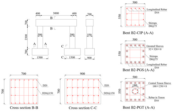
Figure 1.
Geometry and reinforcing details of the bent specimens (unit: mm).
Joint connection details of the two precast bents are shown in Figure 2. In the cap–column joint, grouted splice sleeves were embedded within the cap beam, whereas at the column–footing joint, they were installed at the bottom of the column. Additionally, a 200-mm-long unbonded zone of longitudinal rebar was set below the sleeves to avoid premature failure caused by stress concentration at the joint. For specimen B2-PGT, in addition to using the same grouting splice sleeves’ connection scheme as B2-PGS, a grouted central tenon was also utilized in the cap–column and column–footing joint, forming the proposed GSS-GCT connection.
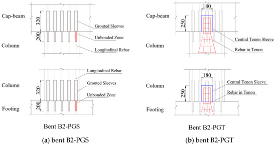
Figure 2.
Details of the connection joints (unit: mm).
The grouted central tenon consisted of rebar and a cylindrical steel sleeve. For the column–footing joint, the tenon was reinforced with six 16-mm-dia. HRB400 rebar, whose bonded length was 650 mm inside the footing and 220 mm inside the tenon. A cylindrical steel sleeve was secured at the bottom of the column during the casting process, creating a cylindrical cavity intended for connecting with the rebar embedded in the footing. The tenon sleeve was 180 mm in diameter, 250 mm in height, and 8 mm in thickness, with an inlet at the bottom and an outlet at the top. When the segments were installed in place, no-shrink high-strength mortar was used to grout the sleeves and central tenon.
2.2. Specimen Fabrication
Figure 3 shows the construction of precast two-column bents, which included B2-CIP, B2-PGS, and B2-PGT.
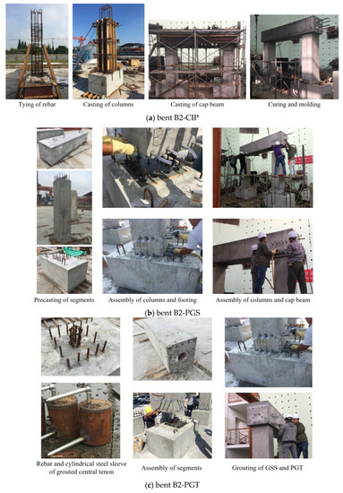
Figure 3.
Fabrication of the three bents.
As shown in Figure 3a, specimen B2-CIP was cast in sections. The longitudinal rebar of the columns had a length of 3.65 m and completely penetrated the footing and cap beam without any splice or mechanical connector.
For bents B2-PGS and B2-PGT, all segments were prefabricated in the factory; see Figure 3b,c. Upon completing the concrete curing process, preassembly work was undertaken to confirm the alignment between the position of all longitudinal rebar at the joint and the grouted splice sleeves. The length of the pre-embedded rebar was scrutinized and adjusted to meet the design drawings. Once the preassembly inspection had been completed, all the segments were transported to the laboratory for assembly. During the assembly, the verticality of the columns was adjusted through a levelling layer. When the segments were installed, a C100 no-shrink high-strength mortar was used to grout the sleeves and central tenon.
2.3. Material Properties
According to the Chinese Standard for Testing Method of Concrete Structures (GB/T 50152-2012) [36], six 150 × 150 × 150 mm cubes were poured from the same batch of concrete of each bent specimen and tested. The mean cubic compressive strength was , equivalent to the mean cylindrical strength of , as shown in Table 2.
Table 2.
Cubic compressive strength of concrete.
Three sample specimens were prepared and examined for both the longitudinal flexural and transverse rebar based on the ASTM (A615/A615M-16 2016) [37]. The measured mechanical properties of the rebar are presented in Table 3.
Table 3.
Mechanical properties of rebar.
In parallel, the spliced rebar embedded within the grouted sleeves was subjected to loading until failure. Each failure instance manifested at the rebar outside the grouted sleeve without any observed debonding within the sleeves.
2.4. Loading Scheme
The quasi-static cyclic test setup and loading scheme are illustrated in Figure 4. The vertical axial force exerted on the top of the column using the jack was 560 kN, as per the axial compression ratio of 6%. The footings were stably fixed in the ground through thread rebar. The two-column bents were subjected to quasi-static cyclic loading with the actuator located 3.35 m above the ground. The actuator’s maximum load capacity and travel distance were 1000 kN and ±250 mm, respectively. In order to clarify the destroy development of two-column piers, use L1~L4, R1~R4 to represent each surface of the left and right columns, as shown in Figure 4a.
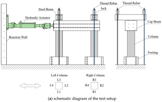
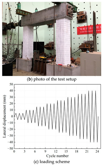
Figure 4.
Test setup and loading scheme.
The horizontal loading history according to preset incremental displacement is shown in Figure 4c. Each cyclic loading step was repeated three times with a given displacement increment. The displacement increment of 5 mm was applied until the ED rebar was fractured or the concrete was severely damaged.
3. Experimental Results and Discussions
3.1. Damage Evolutions and Failure Patterns
For these three two-column bents, the left column is near the actuator side, and the right column is far from the actuator side. The damage progression of the bents was documented during the experiment. For all three bent specimens, the left and right columns exhibited a comparable evolution of damage. For brevity, take the left column as an example for the description of damage evolution.
- ⮚
- Bent B2-CIP
The column remained largely intact with no visible cracks on the surface when the lateral displacement ≤ 5 mm. Initial fractures appeared at the top and bottom of the sides labelled L2 and L4 at = 10 mm. As the lateral displacement increased from 10 to 40 mm, the column gradually developed more cracks, particularly within the areas at the top and bottom. Most of the cracks were distributed within 0–600 mm from the column ends, with no cracks forming in the middle of the column. During the loading process, existing cracks continuously developed, extending from sides L2 and L4 towards sides L1 and L3, with several cracks penetrating to form circumferential cracks. When the displacement reached 45 mm, the development of cracks in the column stabilized, and no new cracks were formed. Slight concrete spalling was observed at the top and bottom of the column when the lateral displacement increased from 45 to 55 mm. Subsequently, at = 60 mm, the continuous spalling of the cover concrete occurred, resulting in the exposure of stirrups and longitudinal rebar. As the lateral displacement increased from 60 mm and 75 mm, large areas of concrete spalling occurred at both the top and bottom of the sides L1 and L3. The concrete was severely damaged, accompanied by the buckling of longitudinal rebar and fracture of stirrups. When the lateral displacement = 75 mm, the load-carrying capacity dropped below 85% of the maximum. The longitudinal rebar fractured at the top and bottom of the column, and the test was terminated. The failure patterns of bent B2-CIP are shown in Figure 5.
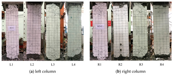
Figure 5.
Failure patterns of bent B2-CIP.
- ⮚
- Bent B2-PGS
When the lateral displacement ≤ 5 mm, the column maintained overall integrity, with no visible cracks on the surface. The seams at the column’s cap–column joint and column–footing joint were not observed to be open. When the lateral displacement = 10 mm, a few visible cracks appeared at the top and bottom of the column on the sides L2 and L4. Specifically, the cracks at the cap–column joint appeared within the 0–200 mm range from the top seam. The cracks at the column–footing joint appeared above the grouted splice sleeve zone, within the 350–500 mm range from the bottom seam. As the lateral displacement increased from 10 to 25 mm, the number of cracks at both ends of the column gradually increased. It is worth mentioning that the number of cracks at the cap–column joint was significantly higher than at the column–footing joint. With the increase in lateral displacement, existing cracks continued to develop and extend from sides L2 and L4 towards sides L1 and L3. At = 30 mm, both the top and bottom seams opened, and the development of cracks in the column stabilized. As the lateral displacement increased from 35 mm and 40 mm, the cover concrete at the top seam of the column was crushed, exposing the unbonded zone of longitudinal rebar. The cover concrete at the bottom of the column was crushed slightly. When the displacement increased from 65 to 70 mm, the spalling of concrete continued at the top and bottom of the column along the direction of the actuator, and the concrete at the joint was severely damaged. When the displacement reached 75 mm, the longitudinal rebar fractured at the cap–column joint and the column–footing joint, leading to the failure of the bent specimen. The failure patterns of bent B2-PGS are illustrated in Figure 6.
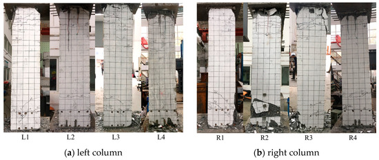
Figure 6.
Failure patterns of bent B2-PGS.
- ⮚
- Bent B2-PGT
When the loading displacement ≤ 5 mm, the column remained largely intact, with no apparent cracks on the surface and no significant opening on the top and bottom seams. When the lateral displacement reached 10 mm, cracks appeared on the top of the sides L2 and L4, about 200 mm from the top seam. Meanwhile, a crack appeared at the bottom of the column, located just above the grouted splice sleeve zone. As the lateral displacement increased from 10 to 30 mm, the number of cracks at both ends of the column gradually increased. New cracks at the bottom occurred within 350–800 mm from the bottom seam, and cracks at the top emerged within a range of 0–600 mm from the top seam. Notably, the number of cracks at the cap–column joint significantly exceeded those at the column–footing joint. As the lateral displacement increased, existing cracks continued to develop and expand, extending from the L2 and L4 sides to the L1 and L3 sides. At = 35 mm, both the top and bottom seams opened. When the displacement reached 40 mm, the development of cracks in the column essentially stabilized, with no new cracks forming. When the displacement increased from 45 to 65 mm, the cover concrete at the top seam of the column was crushed, exposing the unbonded zone of longitudinal rebar. The cover concrete at the bottom of the column was crushed slightly. When the displacement rose from 70 to 95 mm, the continuous spalling of the cover concrete occurred at both ends of the column along the direction of the actuator. The damage range continually expanded, and the concrete at the joints was severely damaged. When the displacement reached 90 mm, the lateral load-carrying capacity dropped to less than 85% of the maximum. The longitudinal rebar fractured at the cap–column joint, and the bent was destroyed. The failure patterns of bent B2-PGT are shown in Figure 7.
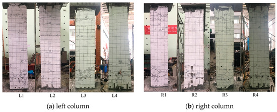
Figure 7.
Failure patterns of bent B2-PGT.
3.2. Strength and Ductility
The experimental hysteretic curves of the three tested bents are shown in Figure 8. For the convenience of observation, only the hysteretic curve for the first loading loop at the same displacement amplitude is given in the figure.
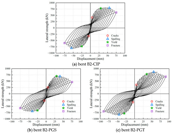
Figure 8.
Hysteretic curves of the bent specimens.
Based on the above hysteretic curves, the skeleton curves of bent specimens can be obtained by connecting the vertices on the hysteretic curves at each displacement amplitude; see Figure 9. Meanwhile, the strength and lateral displacement corresponding to yield point, peak point, and ultimate point are summarized in Table 4.
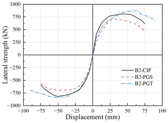
Figure 9.
Skeleton curves of tested bents.
Table 4.
Comparisons of performance variables.
The peak point represents the point of peak lateral strength, and the ultimate point is defined as the point where the lateral strength drops to 85% of the peak strength. The yield point is defined using Park’s method [38], as shown in Figure 10. The skeleton curve in Figure 10 was obtained by taking the absolute mean value of the complete skeleton curve in Figure 9.
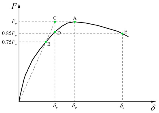
Figure 10.
Equivalent yield displacement determined with Park’s method.
Draw a horizontal line passing through the skeleton curve’s peak point ‘A’ to determine the peak lateral strength . Subsequently, draw a horizontal line at 0.75 , intersecting the skeleton curve at point ‘B’. Then, draw a line from the origin ‘O’ to point ‘B’ and extend it until it intersects with the first horizontal line at point ‘C’. From point ‘C’, drop a vertical line until it intersects with the skeleton curve at point ‘D’. Point ‘D’ represents the yield point, and its corresponding horizontal coordinate is the yield displacement of the specimen.
Generally, bent B2-PGS behaved worse than bent B2-CIP in terms of yield strength (612.88 kN vs. 683.27 kN), peak strength (698.84 kN vs. 810.30 kN), and ultimate lateral displacement (67.85 mm vs. 68.37 mm). Comparatively, the proposed GSS-GCT connection effectively enhanced both strength and ductility. Specifically, compared with the bent B2-CIP, bent B2-PGT increased the yield strength, peak strength, and ultimate lateral drift by 4.2%, 5.4%, and 22.3%, respectively. It is noteworthy that if the displacement ductility factor () is compared, bent B2-PGT performed worse than bent B2-CIP due to its relatively more significant yield displacement.
3.3. Energy Dissipation
The energy dissipation (ED) capacity of the tested bent specimens is comparatively presented, in terms of ED per loop and cumulative ED, as shown in Figure 11. The ED per loop of the bent B2-CIP and bent B2-PGS demonstrates an approximate equivalence. Before the lateral displacement hits 50 mm, bent B2-PGS exhibits superior single-loop energy dissipation capacity. This scenario reverses beyond this displacement threshold, with the B2-CIP outperforming the B2-PGS. As the loading displacement of the two bents nears their ultimate lateral displacement, a decrease in the ED per loop is observed in both specimens. Comparatively, the precast bent B2-PGT with the GSS-GCT connection has less single-loop energy dissipation capacity than the former two. The reason is that the pinching effect of bent B2-PGT is more pronounced, which leads to its single-loop hysteretic loops being not as full as those of the other two bents.
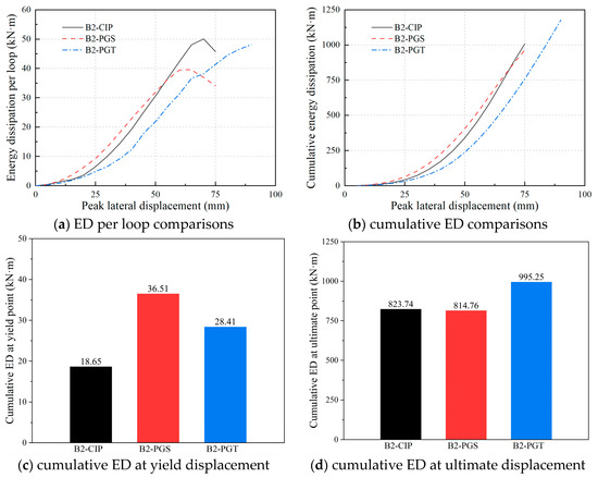
Figure 11.
ED per loop and cumulative ED of the three bents.
Conversely, the cumulative ED of bent B2-CIP is basically the same as that of bent B2-PGS. Bent B2-PGT has a greater cumulative energy consumption capacity than the former two, partly due to its more significant ultimate lateral displacement. Figure 11c compares the cumulative ED from the beginning of the loading to the yield point of the three specimens, representing the cumulative ED when the columns remain elastic. The cumulative ED at the yield point of both precast segmental bents is greater than that of the cast-in-place bent B2-CIP. Figure 11d compares the cumulative ED from the beginning of the loading to the ultimate point, representing the total energy the specimen dissipates during both the elastic and plastic stages. The results indicate that the total energy dissipation of bent B2-PGS at the ultimate point is essentially the same as that of bent B2-CIP. Comparatively, bent B2-PGT demonstrates a more substantial energy dissipation capacity due to its higher load-bearing capacity and ultimate displacement, showing an increase in cumulative ED of 22% compared to bent B2-CIP.
3.4. Residual Displacement
Residual displacement refers to the irrecoverable displacement experienced by a structure after being subjected to seismic activity. Residual displacement versus lateral peak displacement of the three bent specimens is presented in Figure 12. The residual displacement is obtained by taking the absolute mean value of both loading directions.
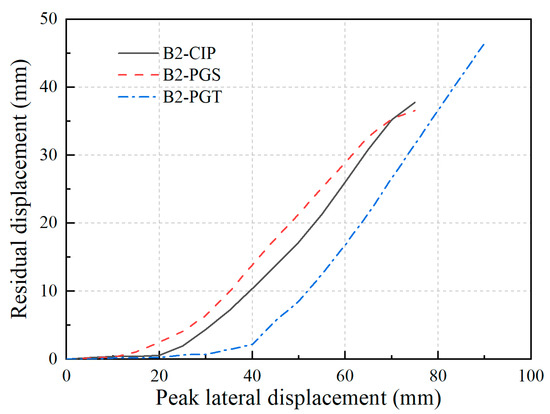
Figure 12.
Residual drifts of the three bent specimens.
The residual displacement of all three bents increases with peak lateral displacement. Among them, B2-PGS exhibits the most significant residual displacement, reaching up to 37.80 mm when the peak lateral displacement = 75 mm. Comparatively, at the same peak lateral displacement, the residual displacement of bent B2-PGT is significantly less than that of B2-CIP and B2-PGS. The results demonstrate that the GSS-GCT connection has a constraining effect and can provide the precast segmental bent with better self-centering capability.
3.5. Pinching Effect
Individual loops of the three bent specimens at the peak lateral displacement of = 25, 50, and 75 mm are compared in Figure 13 to present the pinching effect. The so-called “pinching” occurs when, after unloading from a previous cycle, the initial reloading exhibits relatively low stiffness during the recovery of the residual displacement, and then the stiffness suddenly increases. For two-column bent specimens, the generation of the pinching effect is associated with the failure mechanisms of the plastic hinge zones at both the top and bottom of the columns.
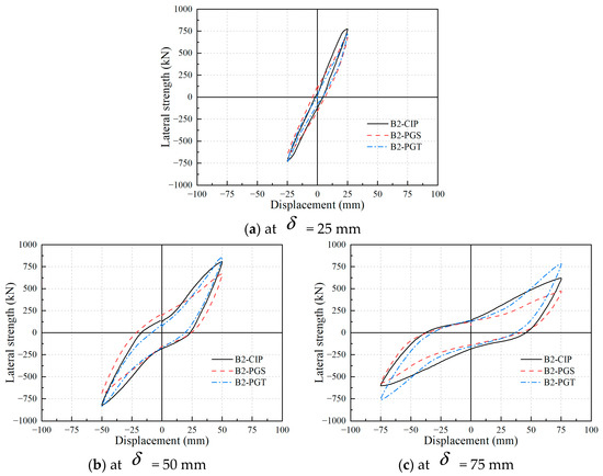
Figure 13.
Pinching effects of tested bents illustrated with individual hysteretic loops.
For the cast-in-place bent B2-CIP, the pinching effect primarily originates from the cracking and crushing of concrete in the plastic hinge zones at both the top and bottom of the columns, along with bond-slip behavior between longitudinal rebar and surrounding concrete/grouted mortar. Upon reloading the bent specimen, a delay is observed in the closure of the cracks in the concrete of the compression zone, which only reseal and restore stiffness after loading reaches a certain extent.
In the two precast bents, since both the grouted splice sleeves and grouted central tenons were embedded within the cap beams above the cap–column seams, the failure modes in the plastic hinge zones at the top of the columns resemble those of the bent B2-CIP. For the bent B2-PGS, an opening emerges at the column–footing interface, and the cover concrete at the bottom of the column gradually becomes crushed during loading. This leads to a scenario during initial loading where the opening angles remain unclosed, thereby inducing the pinching effect. However, for the bent B2-PGT, the presence of grouted central tenons restricts the opening of the column–footing joints, consequently rendering the pinching effect less pronounced than in B2-PGS, particularly at lower displacement amplitudes.
In this study, all the two-column bent specimens exhibit, overall, similar pinching behavior. This is primarily because, in the B2-PGS and B2-PGT specimens, the damage at the top of the columns is notably more severe than at the bottom, significantly contributing to the overall pinching effect.
4. Seismic Assessments with Capacity Spectrum Method
4.1. Capacity Spectrum Method
The capacity spectrum method (CSM) was chosen due to its extensive adaptability and simplicity to various structural behaviors [39]. It is mentioned that this method does not require a priori-defined multilinear simplified behavior; therewith, experimental or numerical results can be applied directly. The CSM operates by converting a structurally intricate system into an equivalent single degree of freedom (SDOF) model and subsequently employing a static nonlinear analysis. The method’s validity is considerably enhanced when the predominant natural vibrational mode aligns with each primary directional axis of the building [40]. Given that the concentrated mass Mk (representing the mass of the upper structure of the bridge) at the cap beams is significantly larger than the mass of the two-column bent itself, all three two-column bent specimens can be simplified as an SDOF system. The procedures of the CSM include the following:
Step 1: the real structure is simplified to the equivalent idealized SDOF system; see Figure 14a.
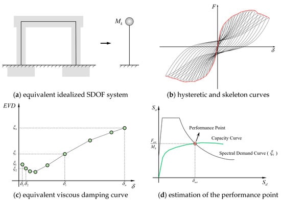
Figure 14.
Capacity spectrum method for evaluating structural performance.
Step 2: the cyclic force-displacement relation (hysteretic curve) and the skeleton curve are obtained from experiments; see Figure 14b.
Step 3: the hysteretic results are analyzed to obtain the values of equivalent viscous damping (EVD) factors subject to each imposed displacement level (Figure 14c).
Step 4: convert the skeleton curve to a capacity curve (Figure 14d), in a pseudo-acceleration versus displacement spectrum ordinate, with
where is the lateral force (unit: kN), is the lateral displacement (unit: mm), and is the structural mass, which is 1.14 × 10⁵ kg (resulting in an axial compression ratio of 6% for the two columns).
Step 5: with the value of the EVD factor associated with a guessed displacement, , a seismic spectral demand curve is obtained; see Figure 14d.
Step 6: plot capacity and demand curves together; see Figure 14d. The demand curve is plotted according to the initial guess value of the equivalent viscous damping (EVD) factor . The performance point is the intersection between the capacity and demand curves, which defines the estimated load and displacement .
Step 7: if the estimated displacement value deviates from the initial guess displacement , then update through interpolation or extrapolation. The EVD factor is subsequently updated based on its corresponding relationship with (Figure 14c).
Step 8: the analysis is looped from step 5 until the convergence = (error less than 1%).
4.2. Evaluation of Equivalent Viscous Damping Curve
The definition of the EVD factors with respect to different displacements is critical in the CSM method. The EVD factor associated with the displacement is obtained based on the proportion of the absorbed energy to the elastic energy:
where is the energy dissipated in the single loop under the displacement , is the elastic deformation energy, and is the viscous damping of the structural material.
The often considers the effect of damage to nonstructural components and potential lack of energy dissipation before yielding in specific numerical models. However, such incorporation may not be appropriate when dealing with purely experimental loops of bare reinforced concrete structures, as in the tests referred to in this study [39]. Regarding the elastic deformation energy , the rectangle half-quadrant method is adopted. This method computes the corresponding to one-eighth of the specific dissipated energy obtained with reference to an equivalent perfect rigid-plastic cyclic behavior (Figure 15) as
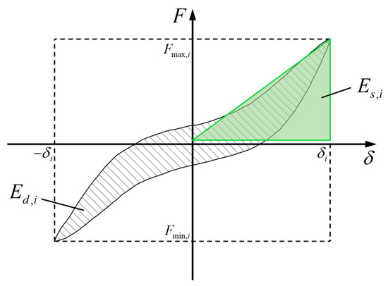
Figure 15.
Definition of dissipated energy.
Relying on the half-quadrant method, the EVD factors associated with different displacement, , of the bents B2-CIP, B2-PGS, and B2-PGT are evaluated and presented in Figure 16. Each value of is the mean value of the three cycles associated with a determined imposed displacement. The equivalent viscous damping increases with the applied lateral displacement for all bent specimens.
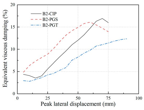
Figure 16.
EVD factors of the bent specimens.
4.3. Seismic Spectral Demand Curve
Seismic demand can be expressed in elastic pseudo-acceleration, , versus the natural period . The pseudo-acceleration response spectra, versus , can be obtained as per AASHTO LRFD Bridge Design Specifications [41]. However, design codes typically provide a calculation method for pseudo-acceleration response spectra that is applicable to a damping ratio of 5%. For other damping ratios, should be modified with a damping discount factor, [42,43], as follows:
with
where is the damping ratio, and the exponent depends on the ground motion characteristics and the nonlinear properties of the system, which affect its equivalent linearization. Here, take .
After obtaining the pseudo-acceleration response spectra , the spectral displacement can be computed as follows:
For each determined natural period , the corresponding and can be obtained with Equations (4) to (6). The seismic spectral demand curve is the curve of versus . Repeat the iterative calculations from Step 6 to Step 8 until = . At this point, the intersection of the capacity curve and the seismic spectral demand curve represents the performance point.
4.4. Limit States’ Definition
Damage states are required to represent a particular level of functionality subject to a certain level of ground motion. Different engineering demand parameters are proposed to quantitatively measure components’ damage levels, i.e., a damage index considering the energy-dissipation capacity and ductility demand [44] and the capacity/demand ratio of bridge columns [45].
This study adopts lateral displacement to characterize the tested piers’ damage levels. Dutta et al. [46] proposed five damage levels for bridge piers based on different drift limits, as shown in Table 5.
Table 5.
Description of defined five damage levels.
Based on the quantitative descriptions of damage levels, the damage evolution of the tested piers was re-evaluated. A displacement increment of 5 mm was applied in the quasi-static tests (refer to Section 2.4). After each loading displacement amplitude, the damage evolution of the piers was closely observed. Through these experimental observations, thresholds of lateral displacements were derived, as shown in Table 6.
Table 6.
Damage levels evaluated with lateral displacements (mm) of tested bents.
4.5. Seismic Assessments with CSM
According to the analysis process of CSM described in Section 4.1, the performance point of each bent specimen under different seismic levels is calculated in Section 4.3. Referring to the damage levels evaluated with lateral displacements in Table 6, the damage levels of the three tested bents can be obtained under each specific peak ground acceleration (PGA), as determined using the methods outlined in ASCE/SEI 7-10 [47]. The estimated lateral displacement , corresponding EVD factors , and damage levels of the specimens are summarized in Table 7.
Table 7.
Seismic assessment of the bent specimens.
The calculation results show that the three two-column bent specimens exhibit no damage when the PGA does not exceed 0.2 g. Upon increasing the PGA from 0.2 g to 0.5 g, all bents display slight damage, indicative of rebar yielding with the associated crack width being less than 1 mm. These findings indicate that the precast segmental two-column bent possesses sufficient structural resilience for applications in moderate- or low-seismicity regions. When PGA increases to 0.6 g, the damage state of the bent B2-PGS pier can be defined as extensive damage, while the other two bents show “moderate damage”. When PGA reaches 0.7 g, all the bents fail.
Through the above analysis, we can conclude that the seismic performance of the bent B2-PGS pier is the worst, while the performance of B2-PGT is similar to that of B2-CIP. This conclusion proves that the proposed GSS-GCT connection is a reliable connection method for a precast two-column bent, which is helpful to improve its seismic performance.
5. Conclusions
This study focuses on the effects of the proposed GSS-GCT connection on the seismic behaviors of precast segmental two-column bents. Three scaled precast two-column bent specimens were fabricated and subjected to quasi-static cyclic tests. Furthermore, the capacity spectrum method was adopted to evaluate the seismic performance of the three bents under the different PGA levels. Several main conclusions can be drawn as follows.
- (1)
- The bent B2-CIP failed with the buckling of longitudinal rebar and fracture of stirrups. Plastic hinges manifested at both the bottom and top of the columns, with nearly identical lengths observed in both locations. The precast two-column bents B2-PGS and B2-PGT failed with longitudinal rebar fracture at the cap–column and column–footing joints, with openings observed at both the top and bottom seams. Notably, for the two precast bents, damage severity was markedly higher at the cap–column joint compared to the column–footing joint. The precast cap beam remained essentially elastic.
- (2)
- The load-carrying capacity and displacement ductility of the bent B2-PGS were marginally inferior to bent B2-CIP, attributable to the discontinuity in segment joints. Moreover, bents B2-PGS and B2-CIP exhibited nearly identical energy dissipation capacity and residual displacement. Nevertheless, using the GSS-GCT connection significantly enhanced the aforementioned four performance indicators of the bent B2-PGT, elevating its seismic performance under high-level earthquakes beyond that of the cast-in-place bent B2-CIP. Hence, precast segmental two-column bents with the proposed GSS-GCT connection could be suitable for high-seismicity regions.
- (3)
- Five levels of the damage state for specimens B2-CIP, B2-PGS, and B2-PGT were qualitatively and quantitatively divided based on experimental observation, which can be evaluated with lateral displacements .
- (4)
- Displacement performance under a given level of peak ground acceleration was assessed using the capacity spectrum method. It was found that all three bent specimens experienced an identical damage level in low-to-medium-level seismic events. Notably, in high-intensity seismic conditions, B2-PGS transitioned into a more critical damage level compared to the other bents, while B2-PGT demonstrated superior performance.
It has been shown that the proposed GSS-GCT connection is promising in improving the seismic performance of precast segmental two-column bents under high-level earthquakes. Future research work is still required to (1) establish an accurate and reliable numerical model for two-column bents using the GSS-GCT connection, (2) propose an analytical method for the load–displacement curve of precast segmental two-column bents, and (3) provide design suggestions for the geometry and reinforcing details of the grouted central tenon.
Author Contributions
Conceptualization, Z.L.; Methodology, S.Z. and G.L.; Validation, T.T. and W.Z.; Formal analysis, S.Z., G.L. and J.H.; Investigation, G.L. and W.Z.; Resources, Z.L.; Data curation, W.Z. and Z.L.; Writing—original draft, S.Z.; Writing—review & editing, T.T. and J.H.; Visualization, S.Z.; Supervision, T.T. and W.Z.; Project administration, W.Z. and Z.L.; Funding acquisition, Z.L. All authors have read and agreed to the published version of the manuscript.
Funding
The project was sponsored by the National Key R&D Program of China (Grant No. 2019YFE0119800), the Scientific Research Foundation for the High-level Personnel of Nanjing Institute of Technology (Grant No. YKJ201985), and the Nanjing Institute of Technology Industrial Economics and Innovation Management Research Institute Open Fund Project (Grant No. JGKB202004).
Institutional Review Board Statement
Not applicable.
Informed Consent Statement
Not applicable.
Data Availability Statement
The data that support the findings of this study are available from the corresponding author upon reasonable request.
Conflicts of Interest
The authors declare that there is no conflict of interest.
References
- Tong, T.; Zhuo, W.; Jiang, X.; Lei, H.; Liu, Z. Research on seismic resilience of prestressed precast segmental bridge piers reinforced with high-strength bars through experimental testing and numerical modelling. Eng. Struct. 2019, 197, 109335. [Google Scholar] [CrossRef]
- Zhuo, W.; Wu, S.; Liu, Z.; Zang, H. Low cyclic loading tests and fatigue damage models of concrete bridge piers reinforced with high-strength rebar. Adv. Struct. Eng. 2021, 24, 706–717. [Google Scholar] [CrossRef]
- Zhuo, W.; Liu, Z.; He, Z.; Zhang, J. Seismic evaluation of precast piers with different rebar strength based on characterized resilience parameters. J. Test. Eval. 2019, 47, 2964–2978. [Google Scholar] [CrossRef]
- Davis, P.M. Unbonded Pre-Tensioned Columns for Bridges in Seismic Regions; Pacific Earthquake Engineering Research Center: Berkeley, CA, USA, 2012. [Google Scholar]
- Ou, Y.C.; Tsai, M.S.; Chang, K.C.; Lee, G.C. Cyclic behaviour of precast segmental concrete bridge columns with high performance or conventional steel reinforcing bars as energy dissipation bars. Earthq. Eng. Struct. Dyn. 2010, 39, 1181–1198. [Google Scholar] [CrossRef]
- Wang, R.; Ma, B.; Chen, X. Seismic performance of pre-fabricated segmental bridge piers with grouted splice sleeve connections. Eng. Struct. 2020, 229, 111668. [Google Scholar] [CrossRef]
- Metelli, G.; Beschi, C.; Riva, P. Cyclic behaviour of a column to foundation joint for concrete precast structures. Eur. J. Environ. Civ. Eng. 2011, 15, 1297–1318. [Google Scholar] [CrossRef]
- Tullini, N.; Minghini, F. Grouted sleeve connections used in precast reinforced concrete construction–Experimental investigation of a column-to-column joint. Eng. Struct. 2016, 127, 784–803. [Google Scholar] [CrossRef]
- Wu, S.; Li, H.; Wang, X.; Li, R.; Tian, C.; Hou, Q. Seismic performance of a novel partial precast RC shear wall with reserved cast-in-place base and wall edges. Soil Dyn. Earthq. Eng. 2021, 152, 107038. [Google Scholar] [CrossRef]
- Yang, S.; Dai, Z.; Yang, X.; Zhou, T.; Tang, L. Analysis of Bonding Performance of Grouting Corrugated Pipes in Fabricated Bridge Structures. Adv. Mater. Sci. Eng. 2022, 2022, 8086155. [Google Scholar] [CrossRef]
- Ling, J.H.; Rahman, A.B.A.; Ibrahim, I.S.; Hamid, Z.A. Behaviour of grouted pipe splice under incremental tensile load. Constr. Build. Mater. 2012, 33, 90–98. [Google Scholar] [CrossRef]
- Hosseini, S.J.A.; Rahman, A.B.A.; Baharuddin, A. Analysis of spiral reinforcement in grouted pipe splice connectors. Građevinar 2013, 65, 537–546. [Google Scholar]
- Kurama, Y.C.; Sritharan, S.; Fleischman, R.B.; Restrepo, J.I.; Henry, R.S.; Cleland, N.M.; Ghosh, S.K.; Bonelli, P. Seismic-resistant precast concrete structures: State of the art. J. Struct. Eng. 2018, 144, 03118001. [Google Scholar] [CrossRef]
- Wang, Z.; Li, T.; Qu, H.; Wei, H.; Li, Y. Seismic performance of precast bridge columns with socket and pocket connections based on quasi-static cyclic tests: Experimental and numerical study. J. Bridge Eng. 2019, 24, 04019105. [Google Scholar] [CrossRef]
- Tazarv, M.; Shrestha, G.; Saiidi, M.S. State-of-the-art review and design of grouted duct connections for precast bridge columns. Structures 2021, 30, 895–909. [Google Scholar] [CrossRef]
- Tong, T.; Zhuo, S.; Liu, Z.; Zhuo, W.; Wang, X. Improving seismic behaviors of precast segmental piers with bonded prestressed tendons. Struct. Infrastruct. Eng. 2022, 1–20. [Google Scholar] [CrossRef]
- Bu, Z.; Guo, J.; Zheng, R.; Song, J.; Lee, G.C. Cyclic performance and simplified pushover analyses of precast segmental concrete bridge columns with circular section. Earthq. Eng. Eng. Vib. 2016, 15, 297–312. [Google Scholar] [CrossRef]
- Liu, Z.; Lei, H.; Tong, T.; Wu, S.; Lu, G. Precast segmental piers: Testing, modeling and seismic assessment of an emulative connection based on a grouted central tenon. Bull. Earthq. Eng. 2022, 20, 2529–2564. [Google Scholar] [CrossRef]
- Ameli, M.J.; Pantelides, C.P. Seismic analysis of precast concrete bridge columns connected with grouted splice sleeve connectors. J. Struct. Eng. 2017, 143, 04016176. [Google Scholar] [CrossRef]
- Ou, Y.C.; Alrasyid, H.; Haber, Z.B.; Lee, H.J. Cyclic Behaviour of Precast High-Strength Reinforced Concrete Columns. ACI Struct. J. 2015, 112, 839–850. [Google Scholar]
- Haber, Z.B.; Mackie, K.R.; Al-Jelawy, H.M. Testing and Analysis of Precast Columns with Grouted Sleeve Connections and Shifted Plastic Hinging. J. Bridge Eng. 2017, 22, 04017078. [Google Scholar] [CrossRef]
- Tong, T.; Wang, J.; Lei, H.; Liu, Z. UHPC jacket retrofitting of reinforced concrete bridge piers with low flexural reinforcement ratios: Experimental investigation and three-dimensional finite element modeling. Struct. Infrastruct. Eng. 2020, 17, 1315–1337. [Google Scholar] [CrossRef]
- Haber, Z.B.; Saiidi, M.S.; Sanders, D.H. Seismic performance of precast columns with mechanically spliced column-footing connections. ACI Struct. J. 2014, 111, 639–650. [Google Scholar] [CrossRef]
- Tazarv, M. Next Generation of Bridge Columns for Accelerated Bridge Construction in High Seismic Zones; University of Nevada: Reno, NV, USA, 2014. [Google Scholar]
- Aida, H.; Tanimura, Y.; Tadokoro, T.; Takimoto, K. Cyclic loading experiment of precast columns of railway rigid-frame viaduct installed with NMB splice sleeves. Proc. Jpn. Concr. Inst. 2005, 27, 613–618. [Google Scholar]
- Ameli, M.J.; Parks, J.E.; Brown, D.N.; Pantelides, C.P. Seismic evaluation of grouted splice sleeve connections for reinforced precast concrete column–to–cap beam joints in accelerated bridge construction. PCI J. 2015, 60, 80–103. [Google Scholar] [CrossRef]
- Zhou, L.; Li, X.; Yan, Q. Performance of Grouting Sleeve-Connected Prefabricated Beams Subjected to Impact Loading. Buildings 2022, 12, 2146. [Google Scholar] [CrossRef]
- Al-Jelawy, H.M.; Mackie, K.R.; Haber, Z.B. Shifted Plastic Hinging for Grouted Sleeve Column Connections. ACI Struct. J. 2018, 115, 1101–1114. [Google Scholar] [CrossRef]
- Bao, L.; Zhao, J.; Teng, F.; Bao, Y.; Zhao, T.; Yu, L. Experimental study on the seismic performance of prefabricated frame piers. Structures 2023, 52, 651–665. [Google Scholar] [CrossRef]
- Zou, S.; Wenliuhan, H.-S.; Mao, Y.-P.; Yu, B.-P.; Zhang, C.-B. Cyclic test and numerical study of seismic performance of precast segmental concrete double-columns. J. Cent. South Univ. 2022, 29, 2502–2512. [Google Scholar] [CrossRef]
- Xia, Z.; Ge, J.; Lin, Y.; Qiu, F. Shake table study on precast segmental concrete double-column piers. Earthq. Eng. Eng. Vib. 2020, 19, 705–723. [Google Scholar] [CrossRef]
- Khaleghi, B.; Schultz, E.; Seguirant, S.; Marsh, L.; Haraldsson, O.; Eberhard, M.; Stanton, J. Accelerated bridge construction in Washington State: From research to practice. PCI J. 2012, 57, 34–49. [Google Scholar] [CrossRef]
- Qu, H.; Li, T.; Wang, Z.; Wei, H.; Shen, J.; Wang, H. Investigation and verification on seismic behaviour of precast concrete frame piers used in real bridge structures: Experimental and numerical study. Eng. Struct. 2018, 154, 1–9. [Google Scholar] [CrossRef]
- Yan, Q.; Chen, T.; Xie, Z. Seismic experimental study on a precast concrete beam-column connection with grout sleeves. Eng. Struct. 2018, 155, 330–344. [Google Scholar] [CrossRef]
- Mehrsoroush, A.; Saiidi, M.S. Cyclic Response of Precast Bridge Piers with Novel Column-Base Pipe Pins and Pocket Cap Beam Connections. J. Bridge Eng. 2016, 21, 04015080. [Google Scholar] [CrossRef]
- GB/T 50152-2012; Standard for Test Method of Concrete Structures. China Architecture and Building Press: Beijing, China, 2012.
- ASTM A615/A615M-16; Standard Specification for Deformed and Plain Carbon-Steel Bars for Concrete Reinforcement. ASTM International: West Conshohocken, PA, USA, 2016.
- Park, R. Evaluation of ductility of structures and structural assemblages from laboratory testing. Bull. N. Z. Soc. Earthq. Eng. 1989, 22, 155–166. [Google Scholar] [CrossRef]
- Lago, B.D.; Molina, F.J. Assessment of a capacity spectrum seismic design approach against cyclic and seismic experiments on full-scale precast RC structures. Earthq. Eng. Struct. Dyn. 2018, 47, 1591–1609. [Google Scholar] [CrossRef]
- Krawinkler, H.; Seneviratna, G. Pros and cons of a pushover analysis of seismic performance evaluation. Eng. Struct. 1998, 20, 452–464. [Google Scholar] [CrossRef]
- AASHTO. AASHTO LRFD Bridge Design Specifications, 4th ed.; AASHTO: Washington, DC, USA, 2007. [Google Scholar]
- EC8. Design Provisions for Earthquake Resistance of Structures; Pub. ENV-1998-2; Comite Europeaen de Normalization: Brussels, Belgium, 1998. [Google Scholar]
- Priestly, M.J.N.; Calvi, G.M.; Kowalsky, M.J. Displacement-Based Seismic Design of Structures; IUSS Press: Pavia, Italy, 2007. [Google Scholar]
- Park, Y.-J.; Ang, A.H.-S. Mechanistic Seismic Damage Model for Reinforced Concrete. J. Struct. Eng. 1985, 111, 722–739. [Google Scholar] [CrossRef]
- Hwang, H.; Jernigan, J.B.; Lin, Y.-W. Evaluation of Seismic Damage to Memphis Bridges and Highway Systems. J. Bridge Eng. 2000, 5, 322–330. [Google Scholar] [CrossRef]
- Dutta, A.; Mander, J.B.; Kokorina, T. Retrofit for Control and Repairability of Damage. Earthq. Spectra 1999, 15, 657–679. [Google Scholar] [CrossRef]
- ASCE/SEI 7-10; Minimum Design Loads for Buildings and Other Structures. American Society of Civil Engineers: Reston, VA, USA, 2010.
Disclaimer/Publisher’s Note: The statements, opinions and data contained in all publications are solely those of the individual author(s) and contributor(s) and not of MDPI and/or the editor(s). MDPI and/or the editor(s) disclaim responsibility for any injury to people or property resulting from any ideas, methods, instructions or products referred to in the content. |
© 2023 by the authors. Licensee MDPI, Basel, Switzerland. This article is an open access article distributed under the terms and conditions of the Creative Commons Attribution (CC BY) license (https://creativecommons.org/licenses/by/4.0/).