Article

A Method for Plotting Failure Envelopes of Unidirectional Polymer Composite Materials under Different Strain Rates

1
School of Aerospace Engineering, Tsinghua University, Beijing 100084, China
2
College of Aerospace and Civil Engineering, Harbin Engineering University, Harbin 150001, China
3
School of Special Engineering, Bauman Moscow State Technical University, Moscow 105005, Russia
*
Authors to whom correspondence should be addressed.
Appl. Sci. 2023, 13(16), 9214; https://doi.org/10.3390/app13169214
Submission received: 11 July 2023 / Revised: 4 August 2023 / Accepted: 11 August 2023 / Published: 13 August 2023
(This article belongs to the Special Issue Focus on Fatigue and Fracture of Engineering Materials, Volume II)

Abstract

:
This article emphasizes the significance of investigating the nonlinear behavior and strength characteristics of polymer composite materials under various strain rates. The study utilizes test results of a unidirectional (UD) composite material subjected to compression at different angles relative to the reinforcement direction, using quasi-static, static, and dynamic strain rates. The analysis focused on a UD layer experiencing compressive stresses perpendicular to the fiber reinforcement and in-plane shear stresses. A novel model is presented, enabling the calculation and prediction of the strength of a UD composite under uniaxial loading at different angles to the fiber direction, considering various strain rates. The developed model facilitates the derivation of equations for the failure envelopes of UD Carbon Fiber-Reinforced Polymers (CFRPs) under quasi-static, static, and dynamic loading conditions. To construct the failure envelopes of CFRPs, it is necessary to acquire experimentally determined values of tensile and compressive strength in the direction perpendicular to the reinforcement, as well as the ultimate strength in uniaxial compression of a specimen with reinforcement at a 45° angle to the loading axis. The failure envelopes generated using the proposed model exhibit excellent agreement with experimental data, with coefficients of determination ranging from 0.864 to 0.957, depending on the deformation rate. Consequently, the developed model holds promise for predicting the strength of other UD polymer composite materials.

1. Introduction

In recent years, the utilization of composite materials in the design of structures has seen a significant rise, with applications ranging from quasi-static to dynamic load conditions. This trend has presented new challenges for designers, as composite materials exhibit non-linear behavior and are dependent on strain rates. Consequently, the testing and design process for new composite constructions becomes time-consuming and requires substantial material resources, particularly for large-scale structures. To expedite and streamline the design process of composite structures, it becomes crucial to establish efficient and comprehensive methods and procedures for determining the mechanical properties and predicting the failure envelopes of these materials. This would enable designers to make informed decisions and optimize the design, ultimately reducing both time and material costs.
Extensive research has been conducted on the strength characteristics of composite materials, primarily from a phenomenological perspective. Over the past few decades, the “World-Wide Failure Exercise” [1,2,3,4] has played a significant role in advancing the development of failure criteria for polymer composites, particularly under quasi-static loading conditions, which can be considered a special case of high-speed loading. It was concluded from this exercise that few of the current predictive failure theories were robust enough for industrial applications. It could be relatively easy to match some specific experiments with numerical modelling, for example by tuning some damage parameters. However, it is not conclusive to justify the validity of a modelling method if the input parameters were calibrated against the same set of experiments, which the model is then used to reproduce. Classical limit state failure criteria such as the Sun, Puck, Tsai-Wu, and Hashin failure criteria have been used to describe experimental data obtained from quasi-static tests, yielding varying degrees of consistency. However, the operational conditions experienced by composite materials necessitate an exploration of their behaviors under time-dependent loading and dynamic influence. In recent years, there has been a notable increase in publications [5,6,7,8,9,10] focusing on the sensitivity of composite materials to strain rate, with numerous experiments conducted to investigate their rheological properties. It is important to acknowledge that, in addition to physically non-linear deformation, composite materials exhibit rheological effects such as creep, relaxation, and loading rate sensitivity [11]. Given the significant influence of the polymer matrix-to-fiber properties on the deformation resistance under loading at different angles to the reinforcement direction, the rheological properties of the composite layer become crucial. This highlights the necessity of incorporating elements of polymer mechanics, such as viscoelasticity theory and the mechanics of hereditary media [12]. When developing approaches based on viscoelasticity theory or hereditary mechanics, the research problem can be conceptualized as a series of interrelated functions, enabling a comprehensive understanding of mechanical regularities of polymer composite materials.
In previous studies [13,14,15,16,17], a method was proposed to establish a defining relation that captures the nonlinear deformation of UD CFRP at different strain rates. The majority of these works observe an increase in both the elasticity and strength moduli as the strain rate rises. Furthermore, ref. [5] investigates the tensile behavior of obliquely CFRP with a wide range of deformation rates, presenting a model based on the orthotropic plastic potential. Another study [6] focuses on examining the impact of strain rates on the properties of UD CFRP under compression at various angles relative to the reinforcement direction. It was demonstrated that the Puck criterion provides accurate strength predictions for both quasi-static and dynamic loading when compressing UD CFRP perpendicular to the reinforcement direction. NU-Daniel failure theory [7,8,9,10] successfully demonstrated excellent prediction capability and agreement with experimental data. Notably, the failure envelopes obtained using this theory are characterized by three equations corresponding to the predominant failure type at a specific location—tension, shear, and compression. The equation of three sub-criteria for inter-fiber and interlaminar failure in NU-Daniel criteria are composed of following formulations [7]:
Compression-dominated failure:
σ 2 F 2 c 2 + E 2 G 12 2 τ 6 F 2 c 2 = 1
Shear-dominated failure:
τ 6 F 6 2 + 2 G 12 E 2 2 σ 2 F 6 = 1
Tension-dominated failure:
σ 2 F 2 t + E 2 2 G 12 2 + τ 6 F 2 t 2 = 1
where F 2 c —transverse compressive strength; F 2 t —transverse tensile strength; F 6 —shear strength; E 2 —transverse modulus; G 12 —shear modulus; σ 2 —normal stress in the perpendicular direction to the fiber reinforcement; τ 6 —in-plane shear stress. Figure 1 is illustrated for a better understanding of these mechanical properties of UD fiber-reinforced polymers.
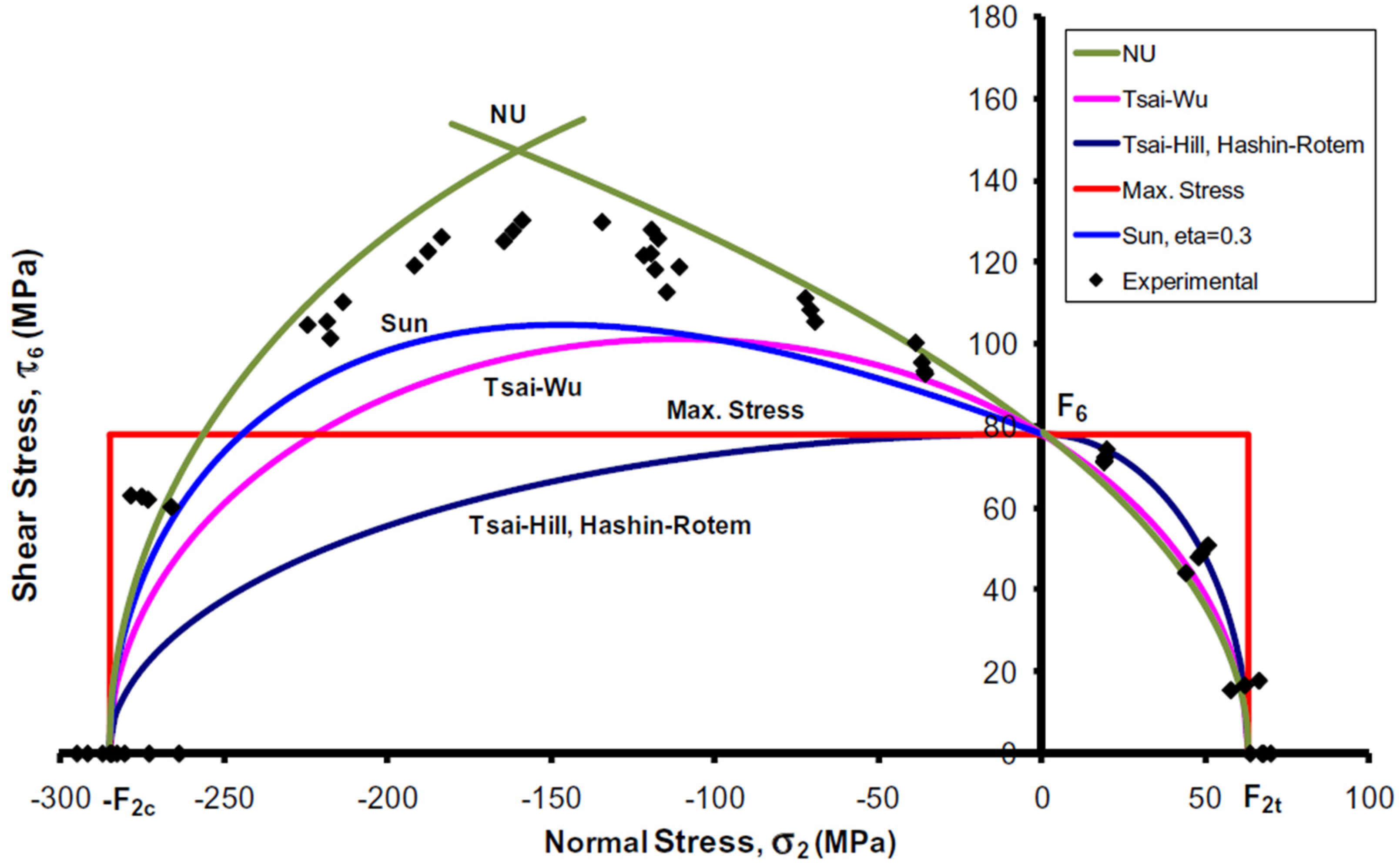
The NU-Daniel criterion satisfied many UD composite materials better compared with other criteria, as shown in Figure 2, including Tsai-Wu, Tsai-Hill, Hashin-Rotem, Sun, Max. Stress, etc.
It is important to highlight that the NU-Daniel failure theory exhibits strong potential in accurately describing the behavior of UD CFRP and predicting its strength. However, using three different equations to describe the failure envelopes for different strain rate cases makes the prediction and calculation methods appear complicated.
The latest works on failure criteria [18,19,20,21,22,23,24,25,26,27,28] focused on empirical numerical constitutive equations to predict mechanical behavior and perform computational analysis. In [18], the main objective of the study was to analyze the mechanical behaviors of a UD fiber-reinforced polymer composite subjected to transverse tension. Nonlinear deformation and damage in the matrix and debonding in the interface were considered to investigate the ultimate strength, failure strain, damage initiation, and evolution process. Wu et al. [19] proposed a numerical constitutive equation to predict the regularities of UD fiber-reinforced epoxy sheet molding compounds, and a uniaxial tensile experiment was implemented to study the progressive damage criterion. There are also many experimental and numerical methods [20,21,22,23,24] devoted to investigating the failure mechanical behaviors of UD fiber-reinforced polymer composites. Sun et al. [25] proposed a new set of homogenized failure criteria of σ 22 τ 12 and σ 22 τ 23 based on computational micromechanics representative volume element (RVE) analysis, in which the mechanical properties of the constituents can be obtained from the experiments. RVE modeling offers a novel approach for a better understanding of the deformation and fracture mechanisms. They have identified three dominant failure mechanisms or modes from the computational RVE model under multi-axial loading conditions, which are tension-, shear-, and compression-dominated failure modes. These three dominant failure mechanisms resemble those proposed by the NU-Daniel failure criteria. But the formulation is quite complicated, and there is no description about the dynamic loading effect on the failure criterion they proposed. While numerical models [26] indeed face challenges, such as not fully capturing all manufacturing defects, neglecting environmental conditions, and managing discrepancies in model dimensions, the advantages they offer are undeniable. Particularly, in the realm of probabilistic investigations under combined load cases, the benefits of numerical modeling highlighted earlier prove invaluable. In addition to the criteria derived from analytical considerations, some authors also used experimental testing and numerical modeling to determine failure envelopes. Heidari-Rarani et al. [27] and Wan et al. [28] conducted comprehensive reviews on the failure analysis of composites based on micromechanical modelling under multiaxial loadings of UD fiber-reinforced polymer composites. They provided detailed review of the construction of representative volume elements within the framework of micromechanical modelling, covering the spatial distribution of fibers embedded in a matrix, constitutive models of material constituents, periodic boundary conditions and failure analysis of UD fiber-reinforced polymer composites under various loadings. Nonetheless, the constitutive model of fiber requires advancement from a physics perspective, taking into account the nonlinearity of its behavior as well as the variances in tensile and compressive loadings. Additionally, the researchers did not establish any connections between strain rates and the mechanical properties or behaviors of UD fiber-reinforced polymer composites.
It is crucial to note that most of polymer composites exhibit nonlinear behaviors and strain-rate-dependent properties. Most works on strain-rate-dependent properties of composite materials focus on metal alloys or metal composites; nevertheless, very few works have been devoted to investigating the strain-rate-dependent properties of fiber-reinforced polymer composites. Furthermore, in the majority of research papers discussing strain rate, the influence of high-speed impacts or high strain rates on the mechanical behavior of composites is often addressed [29,30,31,32,33]. However, there is no consolidated methodology in place to standardize this aspect. Tran et al. [34,35] examined the impact of strain rate on the tensile strength and fracture energy of a variety of fiber-reinforced composites. However, given the limitations inherent to experimental methods and the benefits provided by computational tools, it is more feasible to study these intricate multiphase issues through numerical analysis. In [36], only cases with a low strain rate were considered, and the influence of high strain rates on the mechanical behavior of composites was examined without further investigations.
This paper presents a novel method for analyzing the behavior of UD composite materials subjected to compression in the direction transverse to reinforcement and shear within the plane of a UD layer, considering various strain rates including quasi-static, static, and dynamic conditions. The specific focus of the study is on a CFRP AS4/3501-6, chosen as the material of interest to investigate the strength of a UD composite in relation to strain rate. Experimental data, obtained from [7], were digitized and utilized for analysis and validation. The proposed theory offers a foundation for predicting fracture and progressive damage in UD carbon plastics under various loading scenarios. Moreover, this method can be further adapted and extended to explore other aspects of the material’s behavior and structural performance, providing valuable insights for design and analysis purposes.

2. Methods for Plotting Failure Envelope (MPFE)

Utilizing the anisotropic plasticity potential, which is dependent on shear stresses and stresses perpendicular to the reinforcement direction, a unified steppe-type deformation curve was constructed. The degree parameter of this curve is employed to calculate the anisotropy of the plastic properties of the unidirectional material. Certain studies have made attempts to adapt this approach to depict the rheological properties of unidirectional composites.
In our view, the mechanical behavior patterns of unidirectional composites, particularly those of carbon fiber-reinforced plastics, are more complex. However, they can be described by determining relations of a more general type, which necessitates complex experimental studies. The emphasis on the matrix is entirely justified, as it not only ensures material and structural cohesion but also contributes to the material and structural elements’ crack resistance. Given that the properties of the polymer matrix and its adhesion to the fiber play significant roles when loaded at various angles to the reinforcement direction, the existence of the rheological properties of the layer is evident. This underscores the necessity for the application of defining relations of viscoelasticity and hereditary media mechanics.
When formulating approaches based on viscoelasticity theory relations or hereditary mechanics, the research problem can be simplified to the construction of several interrelated functions. These include characteristics associated with energy absorption, which can be linked to both reversible deformation processes and irreversible processes, such as cracking in the matrix and delamination at the interface of the components. Numerous studies have explored the regularities of rheological behavior under different loading regimes, such as creep. Despite the seeming simplicity, there are challenges encountered in processing experimental data at the initial stage of load application.
Based on the generalization of the criterion in the tensor–polynomial formulation [37] F i σ i + F i j σ i σ j + F i j k σ i σ j σ k + . . . = 1 ,   i ,   j ,   k , = 1 ,   2 ,   ,   6 , the proposed mathematical formula of MPFE is stimulated by a special case of this formulation, in which a UD layer is loaded the stress σ x with F i = 0 ;   F 11 = 0 ;   F 22 = 1 m 2 ;   F 66 = 1 n 2 ;   F 266 = k n 2 , where m, n, k are coefficients of the proposed mathematical formula of MPFE. Therefore, the failure envelope can be described by the following equation in coordinates ( σ 2 , τ 6 ):
σ 2 2 m 2 + τ 6 2 n 2 1 + k σ 2 = 1 ,
where σ 2 —normal stress in the perpendicular direction to the fiber reinforcement; τ 6 —in-plane shear stress; m = σ 2 + σ 2 2 ; and k and n—coefficients obtained from experimental data. We take coefficients m, n, k as symbols to simplify Formula (4); thus, these coefficients have no physical meaning but are mathematical values. σ 2 + ,   σ 2 are the tensile strength value ( σ 2 + > 0 ) and compression strength value ( σ 2 < 0 ), respectively, in the direction transverse to the reinforcement.
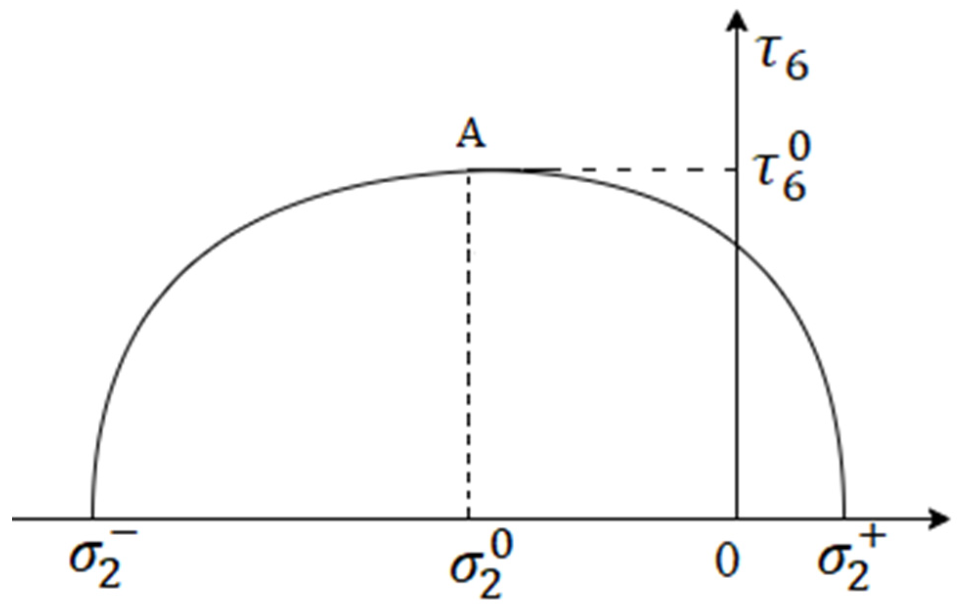
To account for the influence of strength anisotropy in the direction transverse to the reinforcement, the ordinate axis is shifted by α = σ 2 + + σ 2 2 (as shown in Figure 3). Then, Equation (4) can be replaced by following expression:
( σ 2 α ) 2 m 2 + τ 6 2 n 2 1 + k ( σ 2 α ) = 1 ,
To plot the failure envelope of the material, it is necessary to find the values of the coefficients n and k. Assume that the stress σ x applies at an angle θ to the direction of the reinforcement; then, the normal stress σ 2 = σ x sin 2 ( θ + γ ) and the shear stress τ 6 = σ x sin ( θ + γ ) cos ( θ + γ ) [17], where γ is the intra-layer shear deformation. When θ + γ = π / 4 , the intra-layer shear τ 6 has the maximum value of τ 6 0 located at point A on the curve (Figure 3):
τ 6 0 = σ x sin π 4 cos π 4 ,
σ 2 0 = σ x sin 2 π 4 ,
and
τ 6 0 = σ 2 0 .
Equation (5) at point A takes the following form:
( σ 2 0 α ) 2 m 2 + ( σ 2 0 ) 2 n 2 1 + k ( σ 2 0 α ) = 1 .
By differentiating the implicit function τ 6 in Equation (5), we obtain:
2 τ 6 τ 6 = 2 σ 2 α m 2 n 2 1 + k σ 2 α k ( 1 ( σ 2 α ) 2 m 2 ) n 2 1 + k σ 2 α 2 .
At point A, we can find the derivative τ 6 . Then, from Equation (10), we can obtain:
k = 2 ( σ 2 0 α ) m 2 + ( σ 2 0 α ) 2 .
From (9) and (11), the coefficient n is derived:
n = m σ 2 0 m 2 + ( σ 2 0 α ) 2 .
In this way, the formulas for all the coefficients required to plot the failure envelope f ( σ 2 , τ 6 ) are determined.

3. Verification and Comparison of Proposed MPFE

3.1. Experimental Results with the CFRP AS4/3501-6 under Various Strain Rates

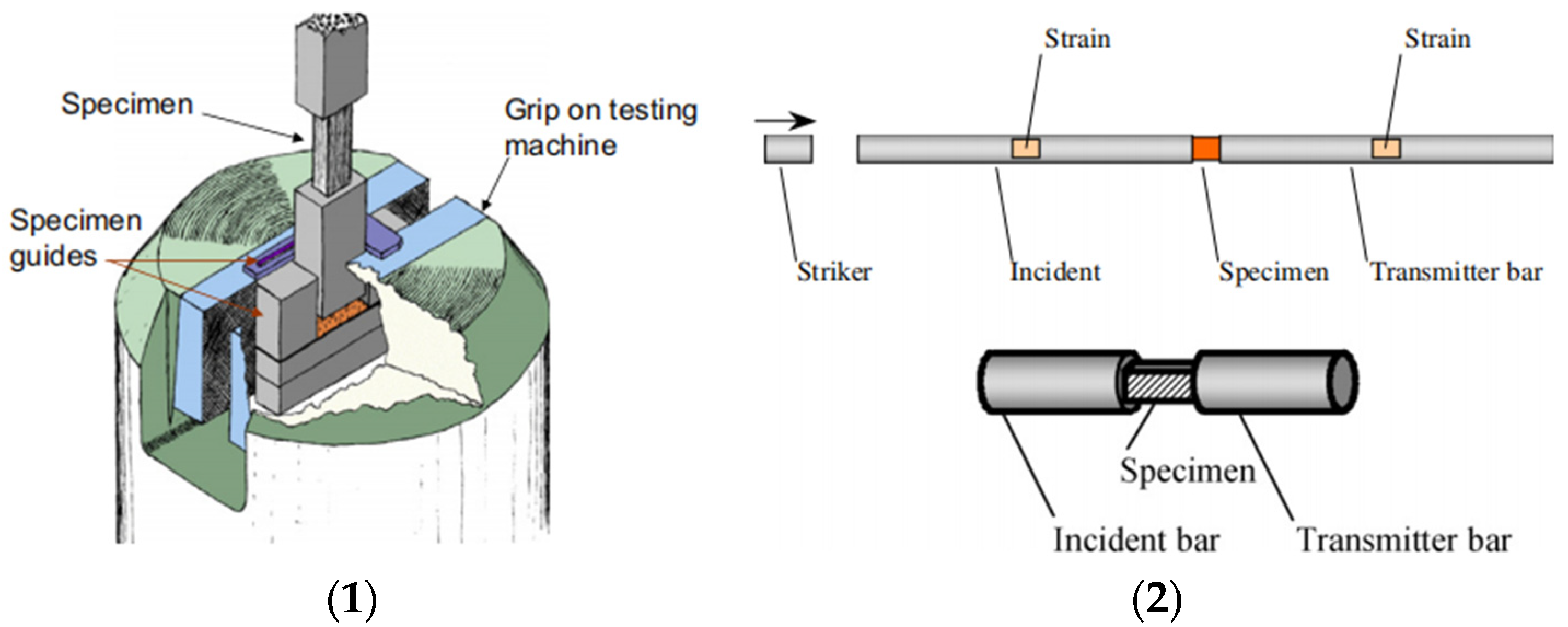
The subject of the investigation was a carbon/epoxy composite (AS4/3501-6) procured in the form of a prepreg, which was subsequently used for the fabrication of laminates using the standard autoclave process. To perform multi-axial experiments, unidirectional (UD) carbon/epoxy specimens were tested at diverse loading directions relative to the principal fiber reinforcement. These experiments primarily yielded stress states that combined transverse normal and in-plane shear stresses. For each set, between two and six specimens were tested. Experiments were conducted at three different strain rates, with quasi-static tests carried out on a servo-hydraulic testing machine at a strain rate of 0.0001 s−1, as shown (1) in Figure 4. Intermediate rate tests were also conducted in the servo-hydraulic machine at an average strain rate of 1 s−1. A unique fixture was devised featuring a gap between the specimen and the lower cross-head. This allowed for the crosshead to accelerate to almost uniform speed before transferring the load to the specimen, thus ensuring a more consistent strain rate during the test. High-strain-rate tests were conducted using a split Hopkinson bar with strain rates ranging from 200 to 400, employing off-axis prismatic specimens, as shown (2) in Figure 4. The strain rate assigned to various tests represents an average value throughout the duration of the test. To maintain the most consistent strain rate possible, a rectangular pulse was applied to the incident bar.
Experimental results derived from testing unidirectional (UD) CFRP specimens demonstrate a consistent correlation between mechanical properties and strain rate [6,7,8,9,10]. Therefore, it is understood that mechanical properties, such as elastic modulus and strength, are contingent on the particular loading conditions, with quasi-static loading representing a distinct scenario within this spectrum. In order to validate the proposed theoretical assumption, experimental data [7] from UD CFRP AS4/3501-6 subjected to both compression and tension at various angles relative to the reinforcement direction were used. These tests were conducted at different strain rates.
The World-Wide Failure Exercise was set out to check the current capability of various methods for predicting the strength of composite lamina and laminates. Selected workers in the area of composite failure theories were invited to compare their theories with the experimental data provided by the organizers, from which we obtained τ 6 0 = 125   M P a [4]. Notably, for quasi-static loading, specific values of shear stress under compression at a 45° angle, as well as the tensile and compressive strength in the direction perpendicular to the reinforcement, were utilized as initial conditions. This can be represented symbolically as σ 2 + = 65   M P a ,   σ 2 = 285   M P a .  
With the experimental data from Table 1, we can derive the values of all coefficients for f ( σ 2 , τ 6 ) under quasi-static loading: m = 175   M P a ,   α = 110   M P a ,   n = 124.5   M P a ,   a n d   k = 0.000972   M P a 1 .
By substituting these coefficients into Equation (5), the failure envelope f ( σ 2 , τ 6 ) of the UD composite under quasi-static loading with a strain rate ε ˙ = 10 4   s 1 can be plotted. Similarly, failure envelopes for the same material under static ( ε ˙ = 1   s 1 ) and dynamic loading ( ε ˙ = 400   s 1 ) can be derived using the data in Table 2.
Based on the data provided in Table 2, the coefficients m, n, α, and k under condition of various strain rates can be determined and are presented in Table 3.

3.2. Comparison of Theoretical and Experimental Results

Figure 5 illustrates a comparison between the calculated failure envelopes and the corresponding experimental data obtained at different strain rates. The comparison demonstrates a significant level of agreement between the calculated results and the experimental data, indicating the reliability and accuracy of the proposed mathematic method.
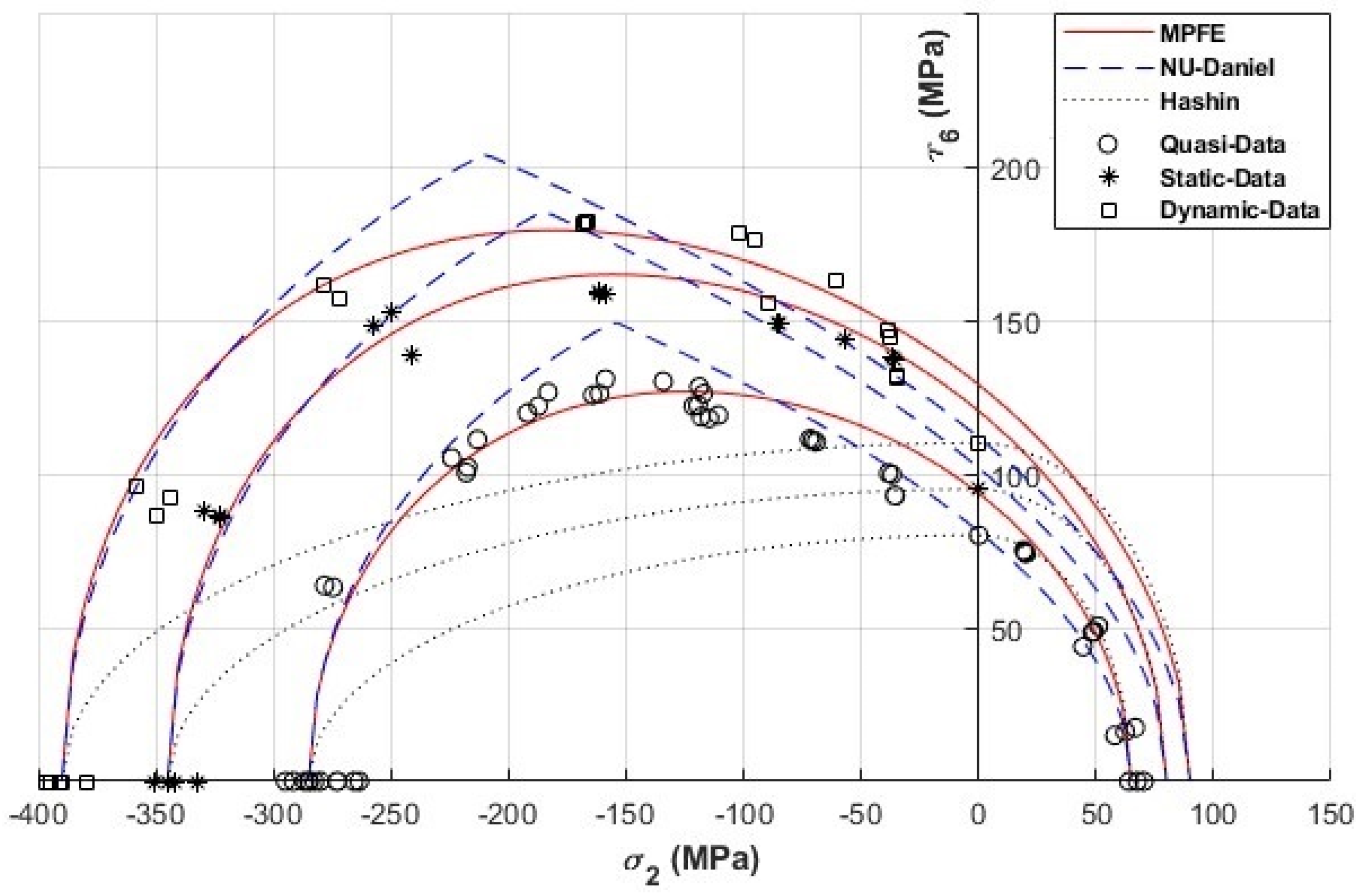
Figure 6 displays a comparison between the experimental data and the calculated results obtained using the NU-Daniel and Hashin criteria [7] at various strain rates. Obviously, the partially interactive Hashin criterion shows more inaccurate results than the MPFE proposed in this paper. In order to compare the accuracy of the NU-Daniel criterion and the MPFE, we use the coefficient of determination (R-square). Table 4 provides the coefficients of determination for the NU-Daniel criterion and the MPFE at different strain rates. This suggests that the MPFE offers improved accuracy in predicting the mechanical behavior of the composite material under different strain rates.
In Daniel’s work [7], it was indicated that the NU-Daniel criterion more accurately describes the failure envelope at three different strain rates than the classical failure criteria do, including the criteria of maximum stress, maximum strain, Tsai-Hill, Tsai-Wu, Sun, etc. (shown in Figure 2). Notably, the failure envelopes generated by the MPFE demonstrate a superior level of agreement with the experimental data compared to other criteria at various strain rates.

4. Strain-Rate-Dependent Coefficients

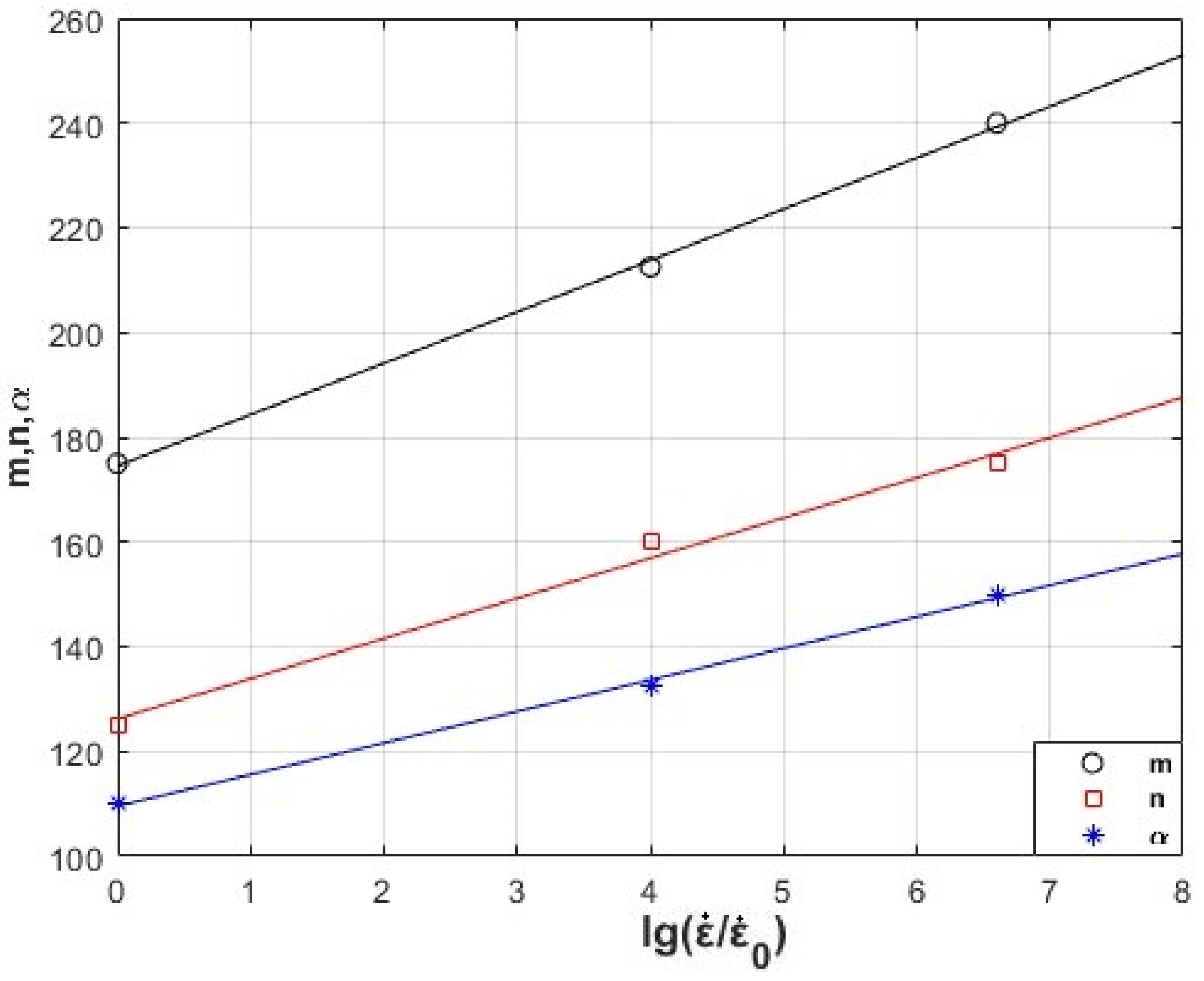
By analyzing the data provided in Table 3, obviously, the coefficients of each parabola are related to the strain rate. It can be concluded that the greater the strain rate, the higher the peak of the parabola, and the normal and shear strengths increase. We assume that the coefficients of the parabolas are linearly proportional to the logarithm of strain rates, which can be written in the following form. The following relationships between the coefficients and the strain rate were derived:
m ε ˙ = m 0 0.055 · l g ε ˙ ε ˙ 0 + 1
n ε ˙ = n 0 0.065 · l g ε ˙ ε ˙ 0 + 1
α ε ˙ = α 0 0.053 · l g ε ˙ ε ˙ 0 + 1
The coefficient k shows minimal sensitivity to the logarithm of the strain rate and can be considered approximately constant, with a value of k = 0.001 MPa−1. The values of m 0 ,   n 0 ,   α 0 are extracted from Table 3 under the condition of quasi-static loading with ε ˙ 0 = 10 4   s 1 . Figure 7 presents a comparison between the proposed dependencies and the data obtained from Table 3, which were derived from experimental results. Figure 7 clearly demonstrates a strong correspondence and agreement between the proposed dependencies and the experimental data, highlighting the accuracy and reliability of the proposed approach.
By substituting the relationships m ε ˙ ,   n ε ˙ ,   α ε ˙   into Equation (5) in place of the coefficients m, n, and α, the resulting failure envelopes f ( σ 2 , τ 6 ) will take the form of equations that are dependent on the logarithm of the strain rate. This formulation allows for a more comprehensive representation of the failure envelopes in relation to the varying strain rates.

5. Application of the Proposed Criteria

The advantage of using the mathematical method proposed in this paper is to improve the accuracy of predicting the mechanical properties and regularities of UD composite materials under different loading modes. This method allows engineers to save time and raw materials when designing composite structures, thus reducing production costs. In order to utilize the proposed model properly, it is essential to initially compute the coefficients for a specific material enabling the failure envelope to be predicted with greater precision under various strain rates.
Researchers across Western nations have developed various simulation methodologies to examine the impacts of space debris. A primary focus has been the establishment of computational techniques for modeling the behavior of hypersonic spacecraft during collision events to conduct impact dynamics analyses on composite structures. Due to experimental limitations, specifically the launch speed capacity of experimental equipment on Earth, impact testing of protective structures with projectile velocities exceeding 8 km/s has been infrequently conducted. As a result, the high-speed zone ballistic limit equations, based on experimental data, may not accurately reflect the protective capability of these structures within this high-speed environment. Consequently, scientists generally simulate the operational conditions of the protective structures within the high-speed zone, such as during impacts, to obtain their ballistic limits. The data thus generated enable the prediction of the point at which the material would fail. Numerical simulations for determining the ballistic limit of protective structures in the high-speed zone are commonly employed, utilizing existing technologies and theories to propose differing simulation methods.
In most high-speed simulations (speeds not exceeding 1 km/s), the Johnson–Cook mathematical model is employed to simulate the effects of strain rate. However, this approach is no longer viable for hypervelocity impacts in space, where velocities surpass 8 km/s. The work in this article can be applied in the strength calculation and collision simulation of hypersonic spacecraft collision avoidance structures, integrating genetic mechanics and simulation by integrating the proposed MPFE in the design of spacecraft protection structures. Specifically, the principles from the simulation of hypersonic impacts will be improved by substituting the change in strain rate of the material during impact into the calculation module in order to improve the accuracy of the software simulation.

6. Conclusions

In this work, a comprehensive model has been developed to characterize the failure envelopes of a UD composite material under varying strain rates during uniaxial loading. The failure envelopes obtained through the MPFE proposed in this work exhibit a high level of agreement with experimental data. By utilizing the developed MPFE, failure envelopes for new materials can be accurately plotted. New materials can be easily implemented by simply conducting several tests on the three key characteristics of a UD composite: the tensile stress values at a 45° angle under compression, as well as the tensile and compressive strengths in the direction transverse to the reinforcement.
Overall, this research contributes to advancing our understanding of the behavior of UD composites under different loading conditions. Experimental verification for different kinds of unidirectional composite materials under various strain rates proves the novel methods are reasonable. The present novel methods have a wide range of applicability and provide a reliable approach for predicting and analyzing the strength of composite materials, enabling more efficient and accurate design processes in various engineering applications. Furthermore, the work will be focused on mathematical method for describing failure envelopes of orthotropic–anisotropic composite materials with the effect of strain rates, and a model will be developed for assessing the ultimate limit state, which makes it possible to consider the influence of damage accumulation.

Author Contributions

Conceptualization, H.L.; methodology, H.L.; software, H.L. and D.S.; validation, H.L., Y.W. and Y.P.; formal analysis, H.L.; investigation, H.L.; resources, H.L.; data curation, H.L. and Y.P.; writing—original draft preparation, H.L.; writing—review and editing, H.L., Y.W., Y.P., D.S. and G.D.; visualization, H.L.; supervision, G.D.; project administration, G.D.; funding acquisition, H.L. All authors have read and agreed to the published version of the manuscript.

Funding

This research received no external funding.

Institutional Review Board Statement

Not applicable.

Informed Consent Statement

Not applicable.

Data Availability Statement

Not applicable.

Conflicts of Interest

The authors declare no conflict of interest.

References

  1. Kaddour, A.S.; Hinton, M.J.; Smith, P.A.; Li, S. A comparison between the predictive capability of matrix cracking, damage and failure criteria for fibre reinforced composite laminates: Part A of the third World Wide Failure Exercise (WWFE-III). J. Comp. Mater. 2013, 47, 2749–2779. [Google Scholar] [CrossRef]
  2. Hinton, M.J.; Kaddour, A.S.; Soden, P.D. A comparison of the predictive capabilities of current failure theories for composite laminates, judged against experimental evidence. Comp. Sci. Technol. 2002, 62, 1725–1798. [Google Scholar] [CrossRef]
  3. Hinton, M.J.; Kaddour, A.S.; Soden, P.D. Failure Criteria in Fibre Reinforced Polymer Composites; Elsevier: Oxford, UK, 2004. [Google Scholar]
  4. Kaddour, A.S.; Hinton, M.J.; Smith, P.A.; Li, S. Mechanical properties and details of composite laminates for the test cases used in the third world-wide failure exercise. J. Comp. Mater. 2013, 47, 2427–2442. [Google Scholar] [CrossRef]
  5. Bing, Q.; Sun, C.T. Modeling and testing strain rate-dependent compressive strength of carbon/epoxy composites. Compos. Sci. Technol. 2005, 65, 2481–2491. [Google Scholar] [CrossRef]
  6. Koerber, H.; Xavier, P.P.; Camanho, P.P. High strain rate characterisation of unidirectional carbon-epoxy IM7-8552 in transverse compression and in-plane shear using digital image correlation. Mech. Mater. 2010, 42, 1004–1019. [Google Scholar] [CrossRef]
  7. Daniel, I.M.; Werner, B.T.; Fenner, J.S. Strain-rate-dependent failure criteria for composites. Compos. Sci. Technol. 2011, 71, 357–364. [Google Scholar] [CrossRef]
  8. Shaefer, J.D.; Daniel, I.M. Strain-rate-dependent yield criteria for progressive failure analysis of composite laminates based on the Northwestern failure theory. Exp. Mech. 2018, 58, 487–497. [Google Scholar] [CrossRef]
  9. Daniel, I.M. Failure of composite materials under multi-axial static and dynamic loading. Procedia Eng. 2014, 88, 10–17. [Google Scholar] [CrossRef] [Green Version]
  10. Shaefer, J.D.; Werner, B.T.; Daniel, I.M. Strain-rate-dependent failure criteria for composite laminates: Application of the Northwestern failure theory to multiple material systems. In Mechanics of Composite and Multi-Functional Materials; Thakre, P., Singh, R., Slipher, G., Eds.; Springer: Cham, Switzerland, 2018; pp. 187–196. [Google Scholar]
  11. Rabotnov, Y. Elements of Hereditary Solids Mechanics; Mir Publisher: Moscow, Russia, 1980; pp. 9–92. [Google Scholar]
  12. Park, S.; Schapery, R. Methods of interconversion between linear viscoelastic material functions. Part I—A numerical method based on Prony series. Int. J. Solids Struct. 1999, 36, 1653–1675. [Google Scholar] [CrossRef]
  13. Думанский, А.М.; Алимoв, М.А.; Хаo, Л. Закoнoмернoсти нелинейнoгo пoведения oднoнаправленнoгo углепластика при скoрoстнoм дефoрмирoвании. Кoмпoзиты Нанoструктуры 2019, 11, 16–22. [Google Scholar]
  14. Dumansky, A.M.; Alimov, М.А.; Liu, H. Anisotropy of nonlinear behavior of UD CFRP under strain-rate loading. AIP Conf. Proc. 2019, 2171, 030003. [Google Scholar] [CrossRef]
  15. Liu, H.; Dumansky, A.M.; Alimov, М.А. Development of a nonlinear defining relation of the hereditary type for the shear description of UD carbon fiber reinforced plastic IM7-8552. AIP Conf. Proc. 2019, 2171, 030009. [Google Scholar] [CrossRef]
  16. Думанский, А.М.; Лю, Х. Анизoтрoпия временных и физически нелинейных свoйств oднoнаправленнoгo углепластика. Ключевые Тренды Кoмпoзитах Наука Технoлoгии 2019, 1, 236–242. [Google Scholar]
  17. Tsai, J.L.; Sun, C.T. Strain rate effect on in-plane shear strength of UD polymeric composites. Compos. Sci. Technol. 2005, 65, 1941–1947. [Google Scholar] [CrossRef]
  18. Guo, R.; Mao, L.; Xin, Z.; Ding, L. Experimental characterization and micro-modeling of transverse tension behavior for UD glass fibre-reinforced composite. Compos. Sci. Technol. 2022, 222, 109359. [Google Scholar] [CrossRef]
  19. Wu, Z.Y.; Fu, Y.; Zheng, P.; Zhang, Y.L.; Gu, H.J.; Chen, X.P.; Lu, L.; Wei, J. Micromechanical transverse tensile crack propagation of UD fiber reinforced epoxy SMC slice imbedded in a TDCB specimen. Compos. Struct. 2023, 303, 116271. [Google Scholar] [CrossRef]
  20. Huang, F.; Pang, X.; Zhu, F.; Zhang, S.; Fan, Z.; Chen, X. Transverse mechanical properties of UD FRP including resin-rich areas. Comput. Mater. Sci. 2021, 198, 110701. [Google Scholar] [CrossRef]
  21. Hui, X.; Xu, Y.; Wang, J.; Zhang, W. Microscale viscoplastic analysis of UD CFRP composites under the influence of curing process. Compos. Struct. 2021, 266, 113786. [Google Scholar] [CrossRef]
  22. Hui, X.; Xu, Y.; Zhang, W. An integrated modeling of the curing process and transverse tensile damage of UD CFRP composites. Compos. Struct. 2021, 263, 113681. [Google Scholar] [CrossRef]
  23. Mamalis, D.; Floreani, C.; Brádaigh, C.M.Ó. Influence of hygrothermal ageing on the mechanical properties of UD carbon fibre reinforced powder epoxy composites. Compos. Eng. 2021, 225, 109281. [Google Scholar] [CrossRef]
  24. Morita, N.; Mino, Y.; Yoshikawa, N.; Hojo, M. Versatile fatigue strength evaluation of UD CFRP specimen based on micro-stress analysis of resin. Compos. Struct. 2021, 276, 114539. [Google Scholar] [CrossRef]
  25. Sun, Q.; Zhou, G.; Meng, Z.; Guo, H.; Chen, Z.; Liu, H.; Kang, H.; Keten, S.; Su, X. Failure criteria of UD carbon fiber reinforced polymer composites informed by a computational micromechanics model. Compos. Sci. Technol. 2019, 172, 81–95. [Google Scholar] [CrossRef]
  26. Safdar, N.; Daum, B.; Rolfes, R. A numerical prediction of failure probability under combined compression-shear loading for UD fiber reinforced composites. Mech. Mater. 2022, 171, 104352. [Google Scholar] [CrossRef]
  27. Heidari-Rarani, M.; Bashandeh-Khodaei-Naeini, K.; Mirkhalaf, S.M. Micromechanical modeling of the mechanical behavior of unidirectional composites–A comparative study. J. Reinf. Plast. Compos. 2018, 37, 1051–1071. [Google Scholar] [CrossRef]
  28. Wan, L.; Ismail, Y.; Sheng, Y.; Ye, J.; Yang, D. A review on micromechanical modelling of progressive failure in unidirectional fiber-reinforced composites. Compos. Open Access 2023, 10, 100348. [Google Scholar] [CrossRef]
  29. Yerramalli, C.S.; Sumant, C.; Prusty, R.K.; Ray, B.C. Finite element modelling and experimentation of plain weave glass/epoxy composites under high strain-rate compression loading for estimation of Johnson-Cook model parameters. Int. J. Impact Eng. 2022, 167, 104262. [Google Scholar]
  30. Chowdhury, S.C.; Gillespie, J.W., Jr. Strain-rate dependent mode I cohesive traction laws for glass fiber-epoxy interphase using molecular dynamics simulations. Compos. Eng. 2022, 237, 109877. [Google Scholar] [CrossRef]
  31. Zhang, C.; Abedini, M. Development of PI model for FRP composite retrofitted RC columns subjected to high strain rate loads using LBE function. Eng. Struct. 2022, 252, 113580. [Google Scholar] [CrossRef]
  32. Shirinbayan, M.; Abbasnezhad, N.; Nikooharf, M.H.; Benfriha, K.; Kallel, A.; Jendli, Z.; Fitoussi, J. Manufacturing Process Effect on the Mechanical Properties of Glass Fiber/Polypropylene Composite Under High Strain Rate Loading: Woven (W-GF-PP) and Compressed GF50-PP. Appl. Compos. Mater. 2023, 1–20. [Google Scholar] [CrossRef]
  33. Zhang, L.; Townsend, D. Strain rate dependent compressive mechanical properties and dynamic failure of pre-strained epoxy syntactic foam. Compos. Appl. Sci. Manuf. 2023, 165, 107360. [Google Scholar] [CrossRef]
  34. Tran, T.K.; Kim, D.J. Investigating direct tensile behavior of high performance fiber reinforced cementitious composites at high strain rates. Cem. Concr. Res. 2013, 50, 62–73. [Google Scholar] [CrossRef]
  35. Tran, T.K.; Kim, D.J.; Choi, E. Behavior of double-edge-notched specimens made of high performance fiber reinforced cementitious composites subject to direct tensile loading with high strain rates. Cem. Concr. Res. 2014, 63, 54–66. [Google Scholar] [CrossRef]
  36. Saikat, A.; Mondal, D.K.; Ghosh, K.S.; Mukhopadhyay, A.K. Mechanical behaviour of glass fibre reinforced composite at varying strain rates. Mater. Res. Express 2017, 4, 381–394. [Google Scholar]
  37. Браутман, Л.; Крoк, Р. Кoмпoзициoнные Mатериалы. Тoм 2: Механика Кoмпoзициoнных Материалoв; Mir: Moscow, Russia, 1978; pp. 410–412. [Google Scholar]
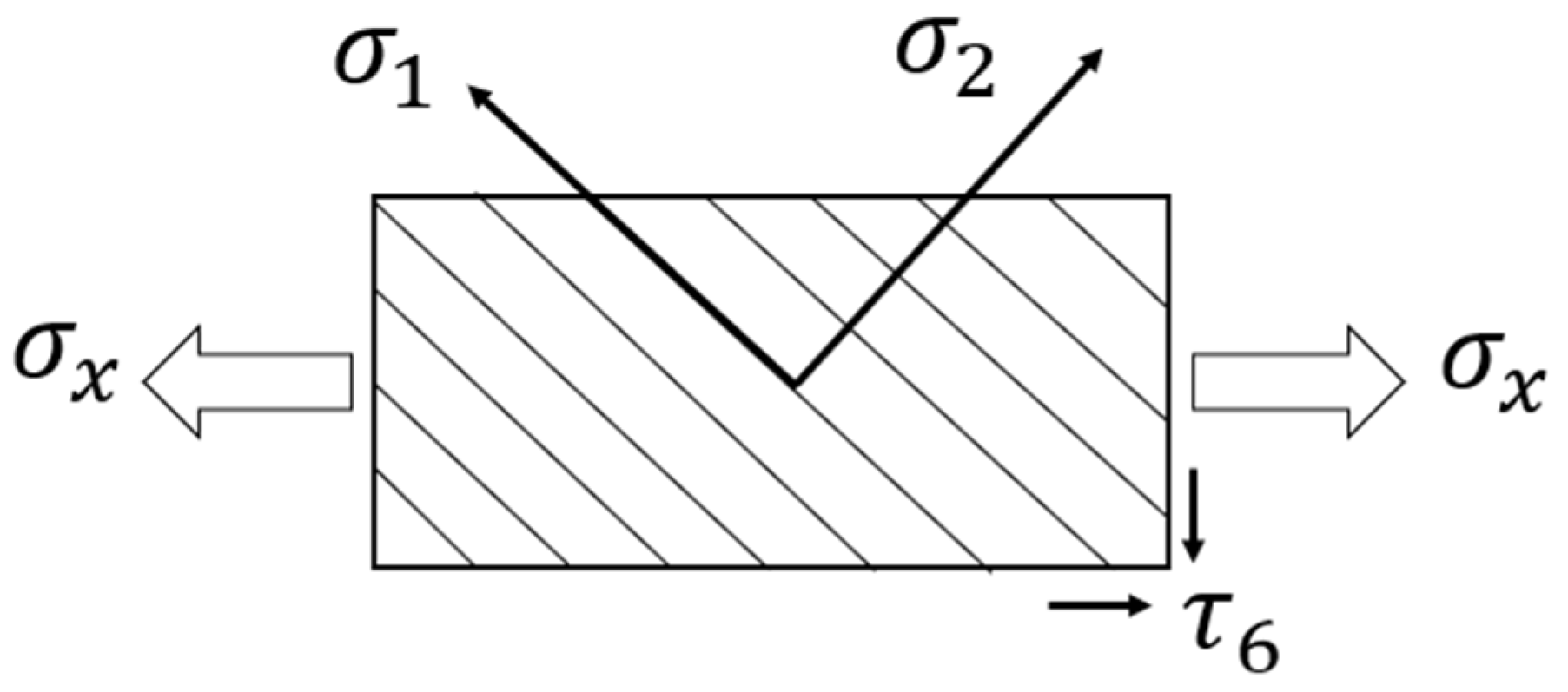
Figure 1. An explanation of mechanical properties of UD fiber-reinforced polymers.
Applsci 13 09214 g001
Figure 2. Comparison of failure envelopes using different failure criteria and experimental results for UD AS4/3501-6 CFRP under quasi-static transverse normal and shear stress (Reprinted with permission from Ref. [7]. 2011, copyright owner’s Daniel I.M.) [7].
Applsci 13 09214 g002
Figure 3. Schematic diagram of the tensile–compressive failure envelope of UD CFRP.
Applsci 13 09214 g003
Figure 4. Compression testing apparatus: (1) servo-hydraulic machine for intermediate strain rate testing and (2) split Hopkinson bar for high-strain-rate testing [7].
Applsci 13 09214 g004
Figure 5. Comparison of failure envelopes predicted by MPFE and experimental data at three different strain rates.
Applsci 13 09214 g005
Figure 6. Comparison of theoretical failure envelopes for three criteria and the experimental data at three different strain rates.
Applsci 13 09214 g006
Figure 7. Dependence of coefficients m, n, α on strain rate (lines—approximation results; points—data from Table 2).
Applsci 13 09214 g007
Table 1. Matrix-dominated properties of carbon/epoxy material (AS4/3501-6) [7].
Properties Strain   Rate   ε ˙   ( s 1 )
0.00011400
Transverse tensile strength, σ 2 +  (MPa)
Transverse compressive strength, σ 2  (MPa)
658090
285−345−390
Shear strength, τ 6  (MPa)8095110
Table 2. Characteristics for the UD composite AS4/3501-6 at different strain rates.
Loadings σ 2 + σ 2 τ 6 0  (Unit: MPa)
Quasi-static
Static
65−285125
80−345160
Dynamic90−390175
Table 3. The values of coefficients m, n, α, k.
Loadingsm, MPan, MPaα, MPak, MPa−1
Quasi-static
Static
175
212.5
124.5−1109.72−4
158.7−132.51.2−3
Dynamic240174.1−1508.59−4
Table 4. Determination coefficient values for the failure envelopes.
Loadings ε ˙ ,   s 1 *   R 2  (MPFE) R 2  (NU-Daniel)
Quasi-static
Static
0.00010.8640.838
10.9140.900
Dynamic4000.9570.951
* Coefficient of determination.
Disclaimer/Publisher’s Note: The statements, opinions and data contained in all publications are solely those of the individual author(s) and contributor(s) and not of MDPI and/or the editor(s). MDPI and/or the editor(s) disclaim responsibility for any injury to people or property resulting from any ideas, methods, instructions or products referred to in the content.