Article

Design and Experiment of the Combined Machine for Transplanting Outcrop of Codonopsis with Micro Ridge Covered with Film

1
College of Mechano-Electronic Engineering, Gansu Agricultural University, Lanzhou 730070, China
2
College of Agriculture and Ecology, Gansu Agricultural Vocational and Technical College, Lanzhou 730030, China
3
Mechanised Agriculture Technology Popularization Station of Gansu Province, Lanzhou 730046, China
*
Author to whom correspondence should be addressed.
Appl. Sci. 2023, 13(16), 9149; https://doi.org/10.3390/app13169149
Submission received: 3 July 2023 / Revised: 26 July 2023 / Accepted: 8 August 2023 / Published: 11 August 2023

Abstract

:
In response to the problem of no supporting equipment for the cultivation of Codonopsis in the hilly and mountainous areas of northwest China, a combined machine for transplanting outcrop of Codonopsis with micro ridges covered with film is designed. The key components of the prototype are analyzed and designed, and the structures and working parameters of the seedbed preparation device, seedling-casting device, rotary tillage soil-covering device, film-covering device, seedling head burial, and film edge soil-covering device are determined. The transmission system scheme is established, and the working mechanism of the core components is analyzed. Field experiments show that when the target seedling spacing is 4.4 cm and the machine moves forward at a speed of 0.1, 0.15, and 0.2 m/s, the variation coefficient of planting spacing and the qualification rate of planting depth meet the standard requirements. The qualified rate of planting posture and film side outcrop are greatly affected by the operating speed of the machine and decrease with the increase in operating speed. When the operating speed reaches 0.1 m/s, the average variation coefficient of planting spacing is 0.08% and the average qualified rate of planting depth, planting posture and film side outcrop is 95.83%, 94.17%, and 93.33%, respectively, which shows that the operating performance is better than that of the operating speeds of 0.15 m/s and 0.2 m/s. This study provides a new reference for the theoretical research and design of mechanized and automated transplanting machinery for Codonopsis seedlings.

1. Introduction

Gansu Province is located at the intersection of the Loess Plateau, the Qinghai-Tibet Plateau, and the Inner Mongolia Plateau. Its complex and diverse landforms, ecological and climatic conditions, and multi-ethnic settlement history have bred rich resources of Chinese medicinal materials. Among them, as a commonly used traditional tonifying medicine in China, Codonopsis can enhance immunity, dilate blood vessels, reduce blood pressure, improve microcirculation, and enhance hematopoietic function. The national planting area of Codonopsis has reached over 800,000 acres, of which 760,000 acres are planted in Gansu Province, which accounts for more than 90% of the country’s output and market share of Codonopsis [1], so Codonopsis has become an important source of farmers’ income in the region. In order to reduce moisture retention and increase soil temperature, Codonopsis planting in this area adopts the film-covered outcrop transplanting technology [2,3]. At present, it is basically finished with manual operation without supporting equipment.
According to the falling posture of seedlings, transplanting mode can be divided into vertical planting, horizontal planting and oblique planting. In order to meet the planting mode and agronomic requirements of different plants, researchers have made many innovations and carried out studies on transplanting machines. The self-propelled pepper transplanter designed by Md Zafar Iqbal et al. [4] has reduced the breakage rate of plastic film caused by working parts and improved the upright degree of seedling transplanting by analyzing and designing the working speed of the gear-driven direct insert mechanism. Luhua Han et al. [5] proposed a self-propelled fully automatic rice transplanter, which combined mechanical, electrical, and pneumatic technologies to realize the automatic feeding and transplanting process of vegetable seedlings, greatly improving the planting efficiency. Xin Jin et al. [6] designed a vegetable single-row transplanting device using mechatronics technology based on tomatoes, which can meet the high-speed transplanting requirements of vegetable seedlings. The above models are mainly used for vertical transplanting of vegetables and other crops. Other scholars carried out horizontal mechanized transplanting of some crops. Wei Yan et al. [7] designed a horizontal sweet potato transplanting machine to achieve horizontal transplanting of naked sweet potato seedlings, which saved labor and improved planting quality. In view of the oblique transplanting mode of naked seedlings, Xu Gaowei et al. [8] developed the oblique transplanting device for Salvia miltiorrhiza film, Wu Guangwei et al. [9] developed the automatic transplanting machine for naked sweet potato seedlings based on pre-treatment seedlings, and Wang Xujian et al. [10] developed the liquorice oblique transplanting ditch cutter. Mulching is essential in the process of pot seedling transplanting in drylands. The compound operation machine designed by Mingjun et al. [11] integrates holes, in-hole fertilization, transplanting, water injection and soil covering in the hole, and mulching, which meets the requirements of mulching and drought resistance, but the film needs to be broken and seedlings be released in the later stage of planting. Dejiang Liu et al. [12] designed a dryland cantaloupe transplanting machine, which realized the precise formation of soil in the seeding hole and solved the problem of transplanting dryland cantaloupe. The whole machine adopted the method of mulching before breaking the film, which reduced the continuous insulation performance of the mulching film. In summary, the existing transplanting machines cannot meet the agronomic requirements of transplanting naked seedlings of Codonopsis, while the labor intensity of manual transplanting and the planting cost are high.
In this paper, according to the agronomic requirements of Codonopsis transplanting, a combined machine for transplanting outcrop of Codonopsis creating a micro ridge covered with film is designed, and field experiments were carried out in order to provide a new reference for the theoretical research and innovative design of mechanization and automatic transplanting machinery of Codonopsis.

2. Structure and Working Principle of the Machine

2.1. Agronomic Requirements

Figure 1 is a schematic diagram of the cultivation mode of Codonopsis outcrop on a micro ridge covered with plastic film. The height of the ridge is 60~80 mm, the row spacing is 700 mm and 300 mm, the film side outcrop width is 0~40 mm, the oblique planting angle of the seedlings is 15°, and the plant spacing is 44 mm. Two bundles of black mulch with a width of 620 mm and a thickness of 0.01 mm are selected to cover the two ridges with a width of 700 mm.

2.2. Operation Procedure

The manual transplanting procedures of Codonopsis seedlings are shown in Table 1, which mainly include seedbed preparation, seedling placement, seedling soil covering, film mulching, and film edge and seedling head soil covering.

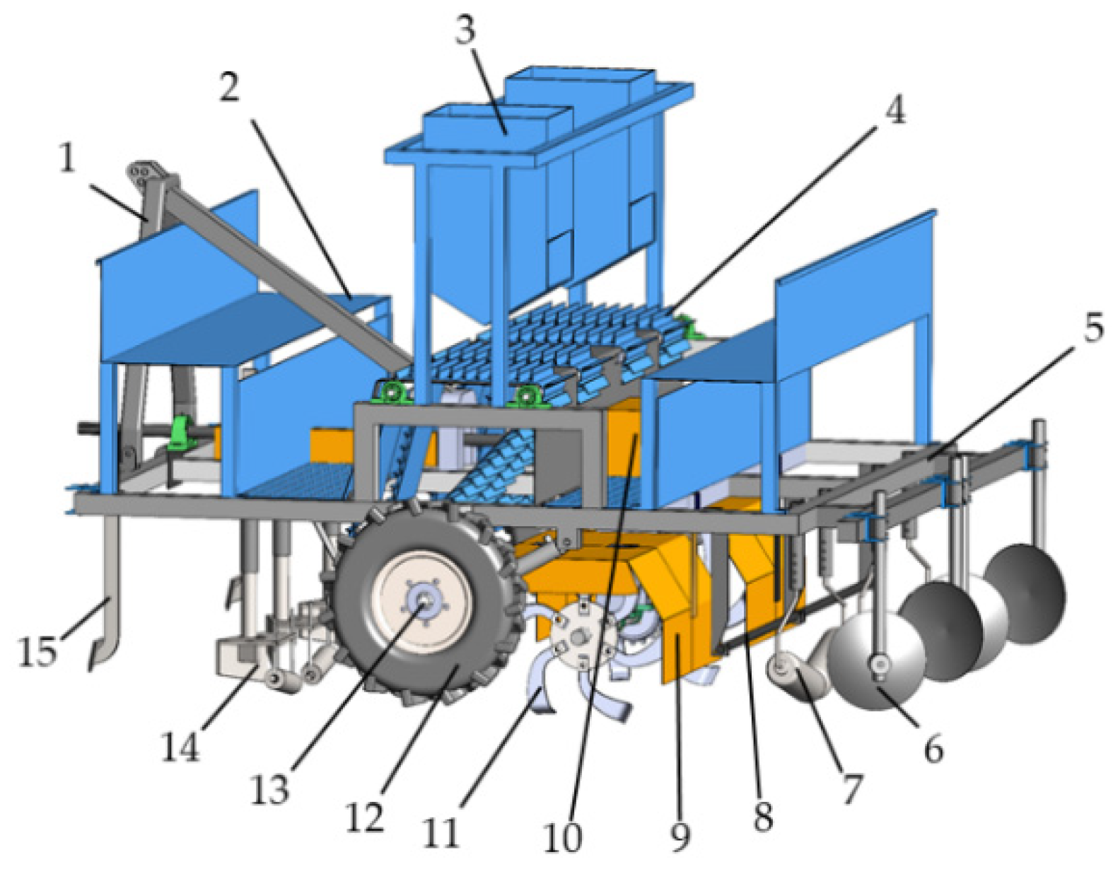
2.3. Structure and Main Technical Parameters of the Machine

As shown in Figure 2, the combined machine for transplanting outcrop of Codonopsis with a micro ridge covered with film is mainly composed of a frame, hanging device, seedbed preparation device, power transmission device, seedling-casting device, rotary tillage soil-covering device, seedling head burial and film edge soil-covering device, etc. The seedbed preparation device, seeding device, and rotary tillage soil-covering device are the main working parts, and the rationality of the design and configuration of these devices directly affects the operating performance of the whole machine. The main technical parameters of the machine are shown in Table 2.

2.4. Working Principle

This machine can complete the ditching and ridging, seedbed preparation, seedling casting, seedling covering, film mulching, film edge and seedling head covering, and other operations at one time. Before the operation, the seedlings are placed on the seeding device manually. The head of the seedlings should be aligned with the high position of the seedbed when placed. During operation, the whole machine is connected to the three-point suspension frame of the tractor through the suspension device. Under the pull of the tractor, the ditch shovel completes the work of ditching and ridging, then, the seedbed preparation device completes the ridge direction scraping, the extrusion of the seedling covering belt, and the forming of the seedbed with the progress of the whole machine. The earth wheel transmits the power to the seedling-casting device through the chain drive, and then the seedling-casting device completes the transmission and casting of the seedlings. The tractor passes the power through the gearbox to the rotary tillage soil-covering device which cuts the soil at high speed and the cut soil is thrown to both sides of the seedbed to cover the seedlings. The film installed on the film-hanging frame can be uniformly coated with the aid of the film-spreading roller. Finally, the covering disk covers the film edge with soil and backfills the ridge. The seedling-casting device can ensure the plant spacing is not affected by the advance speed of the whole machine by making the ground wheel drive the chain so that the seedling spacing is stable.

3. Design of Main Working Parts

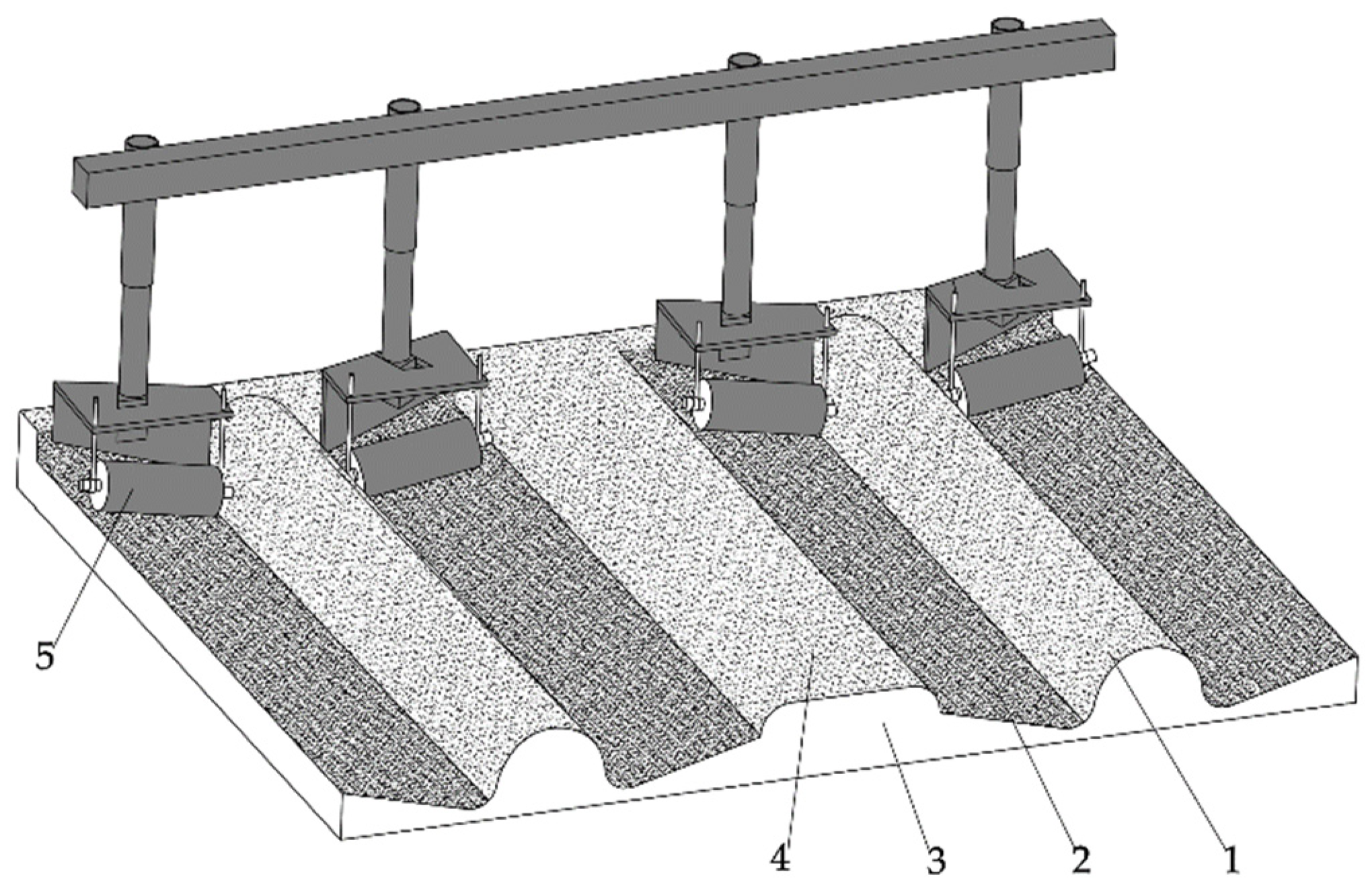
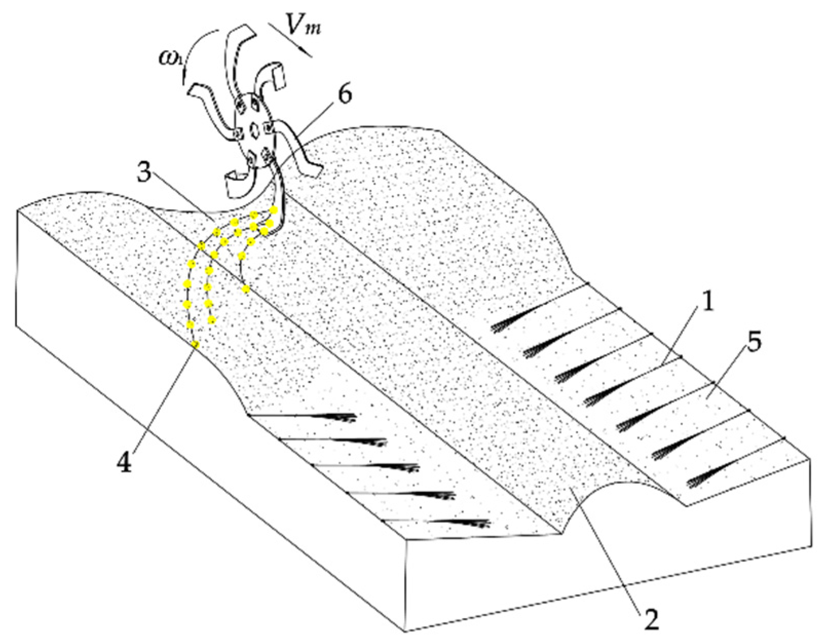
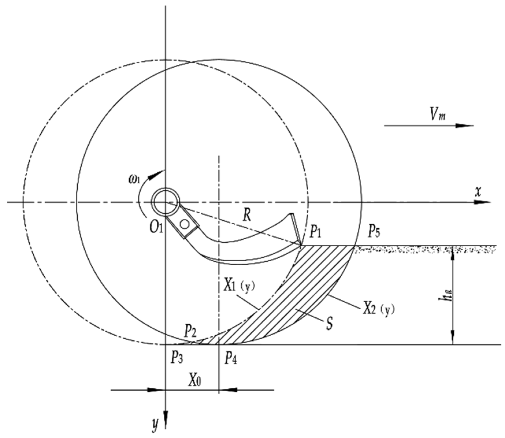
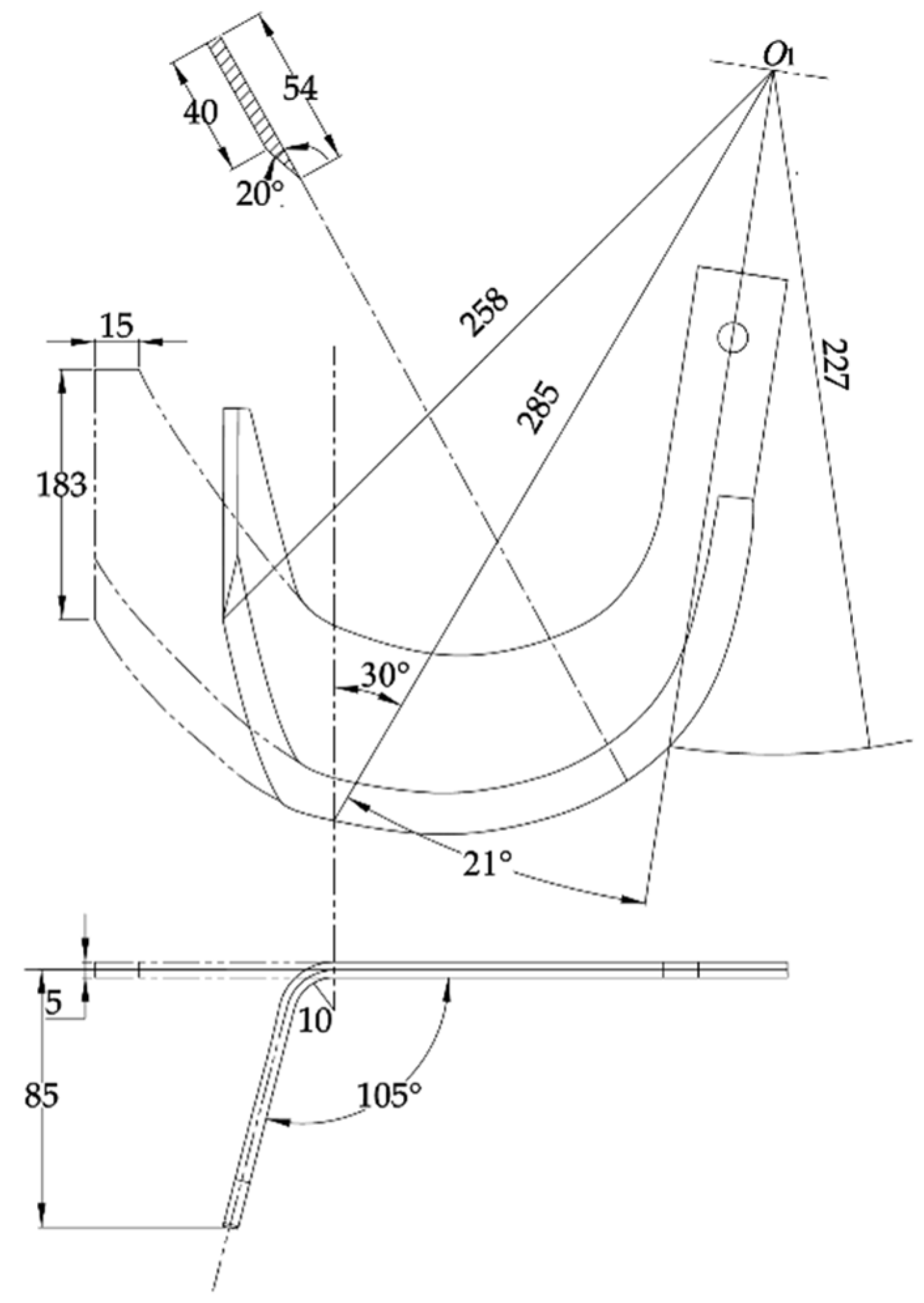
3.1. Seedbed Preparation Device

The seedbed preparation device is one of the core working parts of the combined machine for transplanting outcrop of Codonopsis with micro ridges covered with film. The design and spatial location of the shaper directly affect the quality of seedbed preparation and subsequent seedling casting, thus affecting the overall outcrop effect of Codonopsis seedlings after mulching. Therefore, according to its agronomic requirements, this study included the relevant analysis and calculation of the shaper to achieve the function of seedbed preparation. At the same time, the soil-covering belt of seedlings is formed, which ensures the amount of soil thrown by rotary tillage. A seedbed preparation device is specifically designed, which is connected to the frame. The seedbed preparation device is composed of two shapers, each has a crushing roller and the distance between the two shapers is 200 mm.

3.1.1. Structure and Operation Principle

As shown in Figure 3, the seedbed preparation device is mainly composed of a shaper, crushing roller, crushing roller-regulating rod, connecting rod of the shaper, adjusting rod of the shaper, etc. The structure size and spatial position of the shaper directly affect the molding of the ridge bed and the quality of collected soil in the ridge and furrow. The shaper is made of a 65 Mn steel plate with a thickness of 10 mm. The working surface is designed as a right-angle trapezoid structure. The angle between the hypotenuse and the long right angle is 75°, which can ensure that the angle between the seedlings and the horizontal plane is 15°. In order to ensure that the soil will not exceed the top of the shaper when scraping, the width of the shaper is set to be 330 mm and the length of the short side is 200 mm. The shaper is welded on the connecting rod of the shaper. In order to meet the requirements of different ground conditions, the operator can adjust the shaper up and down through the adjusting rod of the shaper and the adjusting bolt. The crushing roller is installed on the shaper through the adjusting rod of the crushing roller, and its axis is parallel to the bevel of the shaper. The height of the crushing roller can be adjusted through the crushing roller-adjusting rod and adjusting nut. The upper and lower height adjustment of the shaper and the crushing roller and the adjustment of the ground wheel of the operation machine jointly determine the depth of the shaper into the soil and the position of the crushing roller. The adjustable range of the shaper and the crushing roller is 0~150 mm and 0~250 mm, respectively.
Figure 4 shows the operation process of the seedbed preparation device. In the process of seedbed preparation, while the shaper and crushing roller move forward, the crushing roller crushes the soil and suppresses soil moisture. The seedbed and seedling soil-covering belt are formed after the soil is turned through the shaper. When the crushing roller contacts with the soil on the seedbed, it rolls and crushes the soil to overcome the friction force and cohesion between the seedbed and soil particles, compress the gravity water, attached water, and the space between soil particles in the soil layer, and discharge the air in the soil layer [13] so as to ensure the soil particles are closely arranged and the seedbed is flat, thus avoiding the instability of plant spacing, the overall deviation of the seedlings, and poor outcrop.

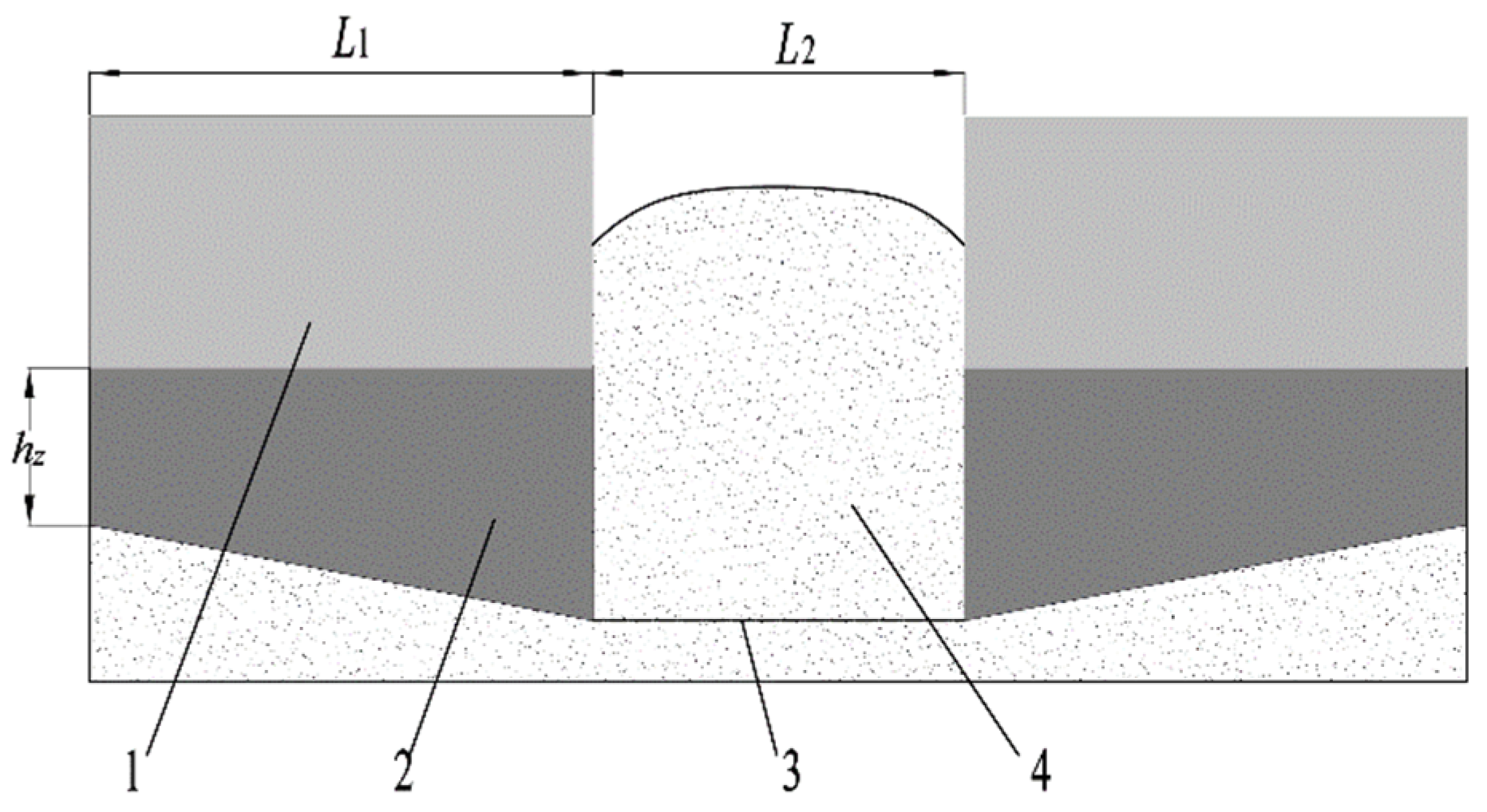
3.1.2. Theoretical Aggregate Amount of Soil

As shown in Figure 5, while moving forward, the shaper needs to push soil in front, transport the soil to the lateral side, and extrude the soil so as to form the soil-covering belt of seedlings. In order to ensure the correct amount of soil collected on the soil-covering belt of seedlings and the thickness of the covering soil on the seedlings in the subsequent rotating tillage process, the amount of soil collected by the shaper needs to be calculated theoretically. The volume of soil collection is calculated through the effective cross-sectional area of the shaper multiplied by a certain length. The amount of soil collected at a forward distance of Y for the entire machine [14] is:
Q 1 = γ Y [ h z L 1 + L 1 2 tan 15 ° 2 + L 2 ( L 1 tan 15 ° + h z ) ]
where Y is the advancing distance of the whole machine which is 1 m;
γ is the bulk density of soil (yellow soil) (1300 kg/m3) [15];
hz is the depth of the short side of the shaper into the soil (0.07 m);
L1 is the cross-sectional length of the shaper (0.25 m);
L2 is the distance between the two shapers (0.2 m).
It can be calculated from Formula (1) that Q 1 = 69.2 kg.
When the advance distance of the whole machine is Y, the amount of covering soil required by the seedlings is
Q 2 = 2 γ Y H L 1 cos 15
where the thickness of covering soil required by seedlings H is 0.07 m.
It can be calculated from Formula (2) that Q 2 = 37.6 kg.
Because Q 1 ˃ Q 2 , the soil collection operation of the shaper meets the theoretical requirement.
Figure 5. Schematic diagram of operation process of the effective cross-section of the shaper. 1. Bulldozing surface. 2 Scraper plane. 3. The action line of the rotary blade tip. 4 The soil-covering belt of seedlings.
Applsci 13 09149 g005

3.1.3. Mechanical Analysis of Shaper

When studying the operation rule of the shaper for collecting soil on the ridge and analyzing the main influencing factors on the quality of collected soil on the ridge, it is found that the quality of collected soil on the ridge is not only related to the structural parameters and soil parameters of the shaper but also to the installation angle of the shaper. Suppose the angle between the working surface of the shaper and the moving direction of the machine is α (that is, the installation angle α), then the larger the installation angle α, the larger the operation width and the greater the resistance of the scraper, which is prone to cause the soil to be piled up [16,17,18]. If the installation angle α is too small, it cannot meet the required width of the seedbed, that is, the installation angle α should be reduced when the required width of the seedbed is met. In order to determine the mechanical conditions of soil scraping along ridges and furrows, it is assumed that there is no relative force between soil particles at the moment of sliding. There is no relative displacement between the soil particles and the working face of the shaper. Figure 6a shows the spatial mechanical analysis of the moment of slip of a single soil particle. Taking the soil particle center as the origin O, the direction parallel to the seedbed as x, the forward direction of the operating machine as y, and the direction perpendicular to the seedbed as z, the space rectangular coordinate system is established. Setting the direction of motion of a single particle at the moment of slip as Az, it is seen that the operation surface slip of the shaper is reciprocated by the combined effects of normal force Fa, friction f, and gravity G. Decomposing the above forces into the xOz coordinate system, as shown in Figure 6b, the resultant force Fx of the soil particle along the x-axis is
F x = F a cos a + G sin 15 ° f cos β sin a
where the angle β is the included angle of Az projection on the surface (°).
Taking the formula of friction f into Formula (3),
F x = F a cos α + G sin 15 ° μ F a cos β sin a
where:
μ is the friction coefficient between the soil particle and operating surface of the shaper;
G is gravity (N).
In Formula (4), the friction coefficient μ between the soil particle and the operating surface of the shaper can be measured. The included angle β is related to the motion direction Az at the moment of slip. The installation angle α can be determined by artificial adjustment. Soil particles will generally move in the positive direction of the x-axis, and the mechanical condition is Fx > 0.
According to the requirements of agronomy, the shaper should not cause soil to be piled up greatly during its operation. When the curved form of the scraper is determined, the installation angle α is the key factor for the formation of the seedbed and the soil-covering belt of seedlings. Field experiments show that the width of the seedbed can be guaranteed when the maximum installation angle α of ridge and furrow soil collection is 60° and the width of the shaper is 330 mm.

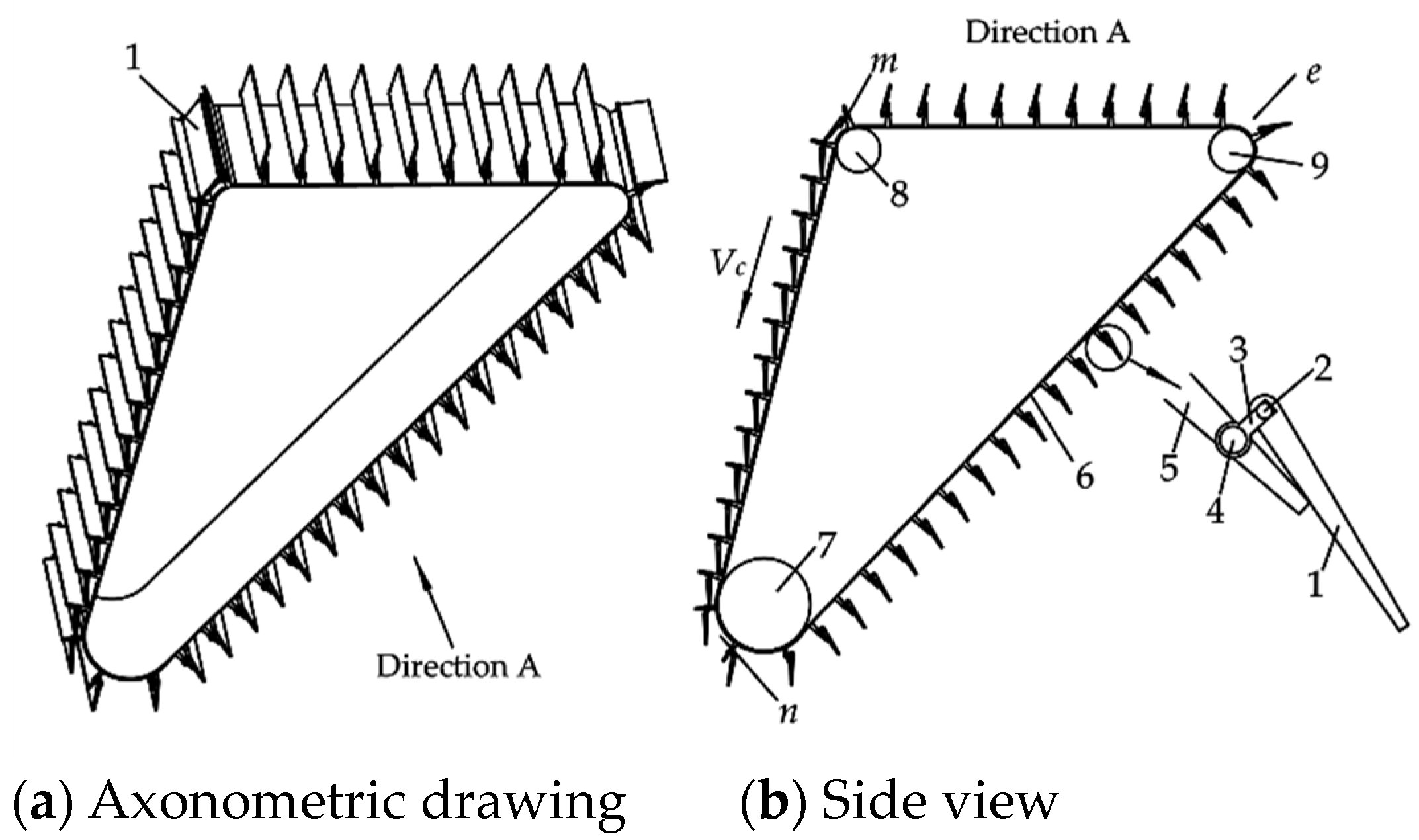
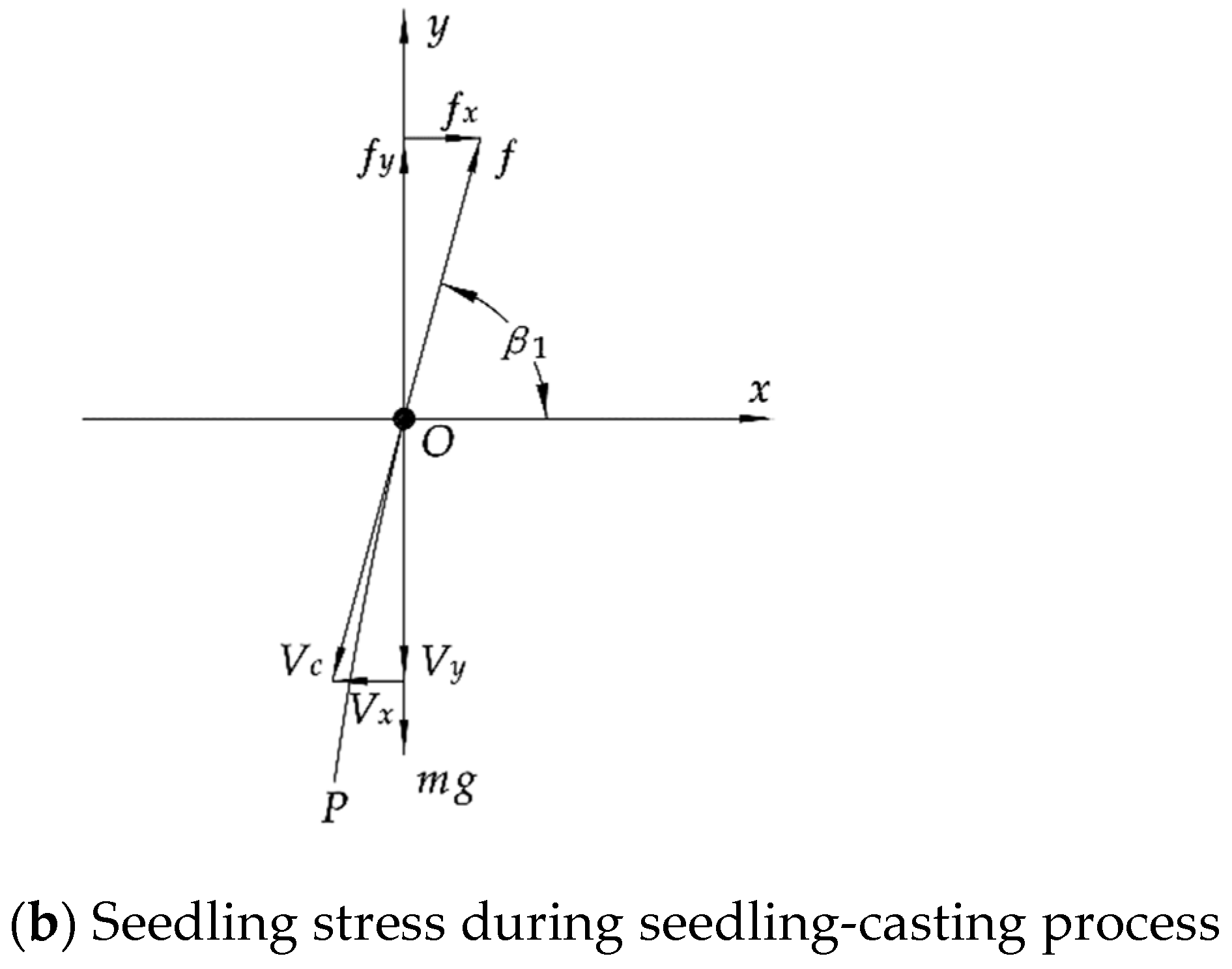
3.2. Seedling-Casting Device

In order to ensure the alignment of the heads of the seedlings when they are placed manually on the inclined plane of the seedbed, it is necessary to reasonably design the seedling-casting device. Currently, the commonly used methods to control seedling spacing include pre-treatment of seedling belt method [9], hole disk seedling belt method [19], and artificial seedling-feeding method [20]. The pre-treatment of seedling belt method requires a lot of preparation work and would consume much time, while the hole disk seedling belt method is suitable for transplanting seedlings with small plant spacing. Therefore, in order to improve the transplanting efficiency and meet the subsequent outcrop cultivation mode of the membrane edge, this design adopts the method of artificial seedling feeding and mechanical auxiliary seedling casting. As shown in Figure 7, the seedling-casting device consists of a seedling protection plate, cylindrical pin, connecting block, fixed pin, seedling separation plate, conveyor belt, driving shaft of the seedling-casting device, driven shaft I, and driven shaft II. They are fixed on the frame, relying on the rotation of the ground wheel to drive the driving shaft of the seeding device which rotates and drives the conveyor belt to move at the speed of Vc. Driven shaft I and driven shaft II support the conveyor belt and cooperate with it to move. Positions m, n, and e are the seedling protection area, seedling-casting area, and seedling-dropping area, respectively. At point e, the seedling protection plate opens due to its dead weight, and seedlings can be placed manually. When seedlings are transported to point m, the seedling protection plate closes under the action of gravity to protect seedlings. When seedlings are transported to point n, the seedling protection plate opens to drop seedlings. The seedling-casting device flexibly uses the self-weight of the seedling protection plate to realize real-time seedling protection and precise seedling casting.

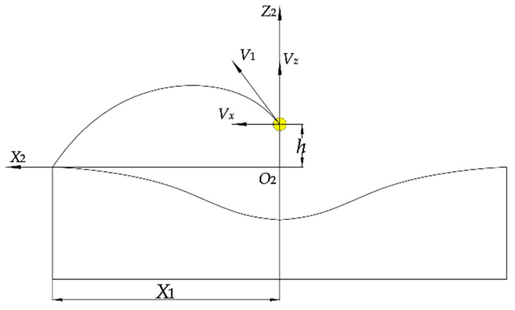
3.2.1. Analysis of Seedling Movement

According to the cultivation mode of Codonopsis outcrop with a micro ridge covered with film, it is necessary to carry out movement analysis of the seedlings’ landing process in order to ensure a small head deviation of seedlings when they are thrown into the seedbed.
Figure 8a shows the side view of the seedling-casting process (the influence of the seedling protection plate on the seedling-casting process is not taken into consideration), in which the driving shaft of the seeding device rotates at angular speed ω, Vm is the advance speed of the whole machine. Suppose that after a seedling is thrown from point O of height H1, the head of the seedling falls to point P and the root falls to point Q, and the horizontal displacement of the seedling is L. Taking the horizontal direction as the x-axis and the vertical plane as the y-axis, a rectangular coordinate system is established.
Air resistance is considered in the seedling-casting process, and it is known that the resistance of air is proportional to its motion speed [21], namely,
ƒ a = μ 1 V t
where ƒa is the air resistance (N);
μ1 is the coefficient of air resistance;
Vt is the seedling speed, m/s.
Without considering the slip of the conveyor belt, the instantaneous speed of seedlings leaving the conveyor belt is equal to the speed of the conveyor belt, namely,
V t = V c
Vc is the speed of the conveyor belt, m/s.
The forces of seedlings during seeding operation are shown in Figure 8b. OP is the motion path of seedlings. At the moment when the seedlings leave point O, their motion is influenced by gravity (mg) and air resistance (ƒa).
Then, the accelerated speed in all directions of the seedlings moving through the air is
{ a x = f x / m a y = ( m g f y ) / m
where a x is the accelerated speed of the seedling in the horizontal direction (m/ s 2 );
a y is the accelerated speed of the seedling in the vertical direction (m/ s 2 );
f x is the air resistance of the seedling in the horizontal direction (N);
f y is the air resistance of the seedling in the vertical direction (N);
g is gravitational acceleration, m/ s 2 .
The instantaneous speed Vc of the seedling is decomposed when the seedling leaves the conveyor belt, and the speed of the seedling in the x and y directions is
{ V x = V m + V c cos β 1 V y = V c sin β 1
By integrating Equation (7), the horizontal and vertical motion velocities of seedlings in the falling process can be written as Vxt, Vyt, respectively,
{ V x t = V m + V c cos β 1 e μ 1 t m V y t = V c sin β 1 + g t e μ 1 t m
V x t is the motion speed of seedlings in the horizontal direction (m/s);
V y t is the motion speed of seedlings in the vertical direction (m/s);
β 1 is the angle between seeding direction and horizontal plane (°);
t is the movement time of seedlings (s).
By integrating Equation (7) again, the displacement of seedlings in the horizontal direction x and in the vertical direction y is
{ x = ( V m + V c cos β 1 ) t + m μ 1 e μ 1 t m y = V c sin β 1 t + g t 2 2 m μ 1 e μ 1 t m
Through the motion analysis of the seedling-casting process, it can be seen that the larger the angle between the seedling-casting direction and horizontal plane, the smaller the horizontal displacement. The speed of the conveyor belt is positively correlated with the horizontal displacement. When the speed of conveyor Vc, the forward speed of machine Vm, and the height of seedling-casting H1 are determined (vertical displacement is determined), then the horizontal displacement is a fixed value.

3.2.2. Analysis of the Collision Process between Seedlings and Seedbed

According to the characteristics of the seedbed, the head of the seedling contacts with the seedbed first in the falling process. After that, the lower the instantaneous speed of the seedling, the smaller the deviation of the seedling. According to the law of conservation of momentum,
M V 0 = M V 0 + i = 1 n m i V i
where M is total mass of seedlings (g);
V 0 is the instantaneous speed of seedlings while contacting with the seedbed (m/s);
V 0 is the instantaneous speed of seedlings after colliding with the seedbed (m/s);
m i is the mass of a single soil particle (g);
V i is the instantaneous speed of a single soil particle after collision (m/s).
Equation (11) shows that the speed of seedlings after collision is V 0 .
V 0 = V 0 i = 1 n m i V i M
It can be seen from the above equation that after the collision between the seedlings and the inclined plane, in order to make the instantaneous speed of the seedlings V 0 low (the deviation of the seedlings should be small after the collision), the soil on the seedbed should not be too solid.
Through the analysis of the collision process between the seedlings and the seedbed, it can be seen that whether the seedlings can be cast successfully is related to the angle between the direction of seeding and the horizontal plane β1 and the soil firmness of the seedbed. During the test, in order to reduce the influence of air resistance on the effect of seeding, the angle between the seeding direction and the horizontal plane should be large. After comprehensive consideration, it is reasonable to set β1 to be 60°, while the seeding height H1 is low, so it can be set to be 80 mm.

3.3. Rotary Tillage Soil-Covering Device

A rotary tillage knife can throw soil from the lateral side [22,23] and, while in operation, the tractor transfers power to the gearbox to change the speed of the power and drive the rotary tillage soil-covering device, so the rotary tillage knife can break soil on the seedling soil-covering belt, ditch, and throw soil on both sides of the seedbed to complete the seedling soil-covering operation. In order to ensure that soil on both sides of the seedbed is uniform in the process of rotary tillage, the rotary tillage knife on the cutter head adopts the external installation method, and the rotary tillage knife at both ends of the cutter head bends outwards. The rotary tillage knife arrangement is shown in Figure 9.

3.3.1. Analysis of Soil-Covering Amount of Rotary Tillage Knife

The rotating direction of the rotary tillage knife is the direction of soil throwing [24]. The process of the rotary tillage knife throwing soil is shown in Figure 10. The advance speed of the machine is Vm, the rotary tillage knife rotates at an angular speed ω 1 , and the soil is thrown up by the rotary tillage knife to position and cover the seedlings. In order to ensure that the thickness of covering soil on seedlings is 40~80 mm, it is necessary to analyze the soil-covering amount of the rotary tillage knife on the seedbed. Firstly, the soil-cutting area of a single rotary tillage knife in a single rotation period is analyzed [25].
In order to establish the parameter equation of the soil disturbed by the rotary tillage knife, the area of soil (S) cut by a single rotary tillage knife in a certain cycle is determined at first, then the thickness of soil (T) cut by a single rotary tillage knife in a certain cycle is obtained, and finally the area of soil (V) disturbed by the rotary tillage knife is obtained. A rectangular coordinate system was established as shown in Figure 11. The motion curve of the blade end of the adjacent rotary tillage knife in the same direction in a certain cycle is established. The blade pivot (O1) is taken as the center, the forward direction of the machine is the x-axis, and the vertical downward axis is the y-axis. The absolute motion of the rotary tillage knife’s end is the combination of rotation motion of the blade pivot and forward motion of the machine, and the motion process of the end of the rotary tillage knife meets the requirements of trochoid [26].
As shown in Figure 11, since the area enclosed by points P2, P3, and P4 is torn apart by the cutter teeth during high-speed rotation, the soil-cutting area S is enclosed by points P1, P3, P4, and P5. The soil-cutting area of a single rotary tillage knife in a single rotation period is expressed as
S = 0 h a d y x 1 ( y ) x 2 ( y ) d x
where:
x 1 ( y ) is the equation of the motion curve of the first rotary tillage cutter end;
x 2 ( y ) is the equation of the motion curve of the second rotary tillage cutter end in the same period.
The equation of the motion curve of the first rotary tillage cutter end is
{ x = R cos ( ω 1 t ) + V m t y = R sin ( ω 1 t )
If the number of blades in the same direction is 3, then the lag soil-covering angle of the second rotary tillage knife in the same direction is 2 π 3 , and the equation of motion curve of the second rotary tillage cutter end in the same direction is
{ x = R cos ( ω 1 t 2 π 3 ) + V m t + x 0 y = R sin ( ω 1 t 2 π 3 )
where x 0 is the pitch of soil cutting, and its coordinates meet
x 0 = 2 π V m Z ω 1
where:
Z is the number of rotary tillage knives in the same direction, 3.
By synthesizing Equations (13)–(16), it can be calculated that the soil-cutting area S is
S = 0 h a x 2 ( y ) d y 0 h a x 1 ( y ) d y
From the equation, times t1, t3, t4, and t5 of the rotary tillage knife passing through P1, P3, P4, and P5 can be calculated as
{ ω 1 t 1 = sin 1 ( 1 h a R ) t 3 = π 2 ω 1 t 4 = 7 π 6 ω 1 t 5 = t 1 + 2 π 3 ω 1
where: t is time (s);
ha is the tillage depth (mm);
R is the radius of the rotary tillage knife (mm);
ω 1 is the angular speed of the rotary tillage blade (rad/s).
Combined with Equations (17) and (18), the soil-cutting area S can be calculated as
S = A cos 2 ω 1 t 1 + B sin 2 ω 1 t 1 + C cos ω 1 t 1 + D sin ω 1 t 1 1 2 R 2 t 1 + E ω 1
where:
{ A = ( ω 1 + 3 ) R 2 8 ω 1 B = ( 1 + 3 ω 1 ) R 2 8 ω 1 C = 3 3 + 3 x 0 R + 3 R V m 3 3 ω 1 R V m t 1 2 3 R V m 6 ω 1 D = 3 3 3 R V m t 1 3 3 x 0 R + 2 π R V m + 3 ω R V m t 1 + 3 3 R V m 6 ω 1 E = 12 3 + 14 π R V m ( 6 π + 3 3 + 3 ω 1 ) R 2 12 3 x 0 R 24 ω 1 2 R V m + 3 π R V m 4 ω 1 2
The area of soil cut by a single rotary tillage knife in one rotation cycle can be approximately calculated as the product of the area of soil cutting and the thickness of soil cutting T, and the formula for calculating the thickness of soil cutting T is [27]
T = L 1 sin ( π θ )
where L1 is the cutting length of the rotary tillage knife’s tangent edge, mm;
θ is the angle of the tangent edge.
According to Equations (19) and (21), the covering volume V of a seedbed soil-covering belt for one rotation of the blade pivot is
V = T S Z = 3 L 1 sin θ ω 1 [ A cos 2 ω 1 t 1 + B sin 2 ω 1 t 1 + C cos ω 1 t 1 + D sin ω 1 t 1 1 2 R 2 t 1 + E ]
According to Equations (18), (20) and (22), the volume of disturbed soil V is related to such parameters as ω1, R, L1, θ, ha, Z, and Vm. When the parameters of the rotary tillage knife are determined, R, L1, and θ are fixed values, so the amount of soil of the seedbed is mainly affected by the depth of tillage ha, rotary angular speed ω1, numbers of rotary tillage knives Z, and forward speed of the machine Vm. When the forward speed of the machine Vm is certain, the rotation angular speed and tillage depth are the main factors affecting the soil thickness. Therefore, the adjustment of the depth of rotary tillage is taken into consideration in the design of the component.

3.3.2. Analysis of Axial Soil-Transporting Performance of Rotary Tillage Knife

In order to ensure the axial covering range of soil while the rotary tillage knife tills soil, it is necessary to determine the mechanical conditions of soil axial movement. The force of rotary tillage is mainly determined by the structural parameters and soil parameters of rotary tillage. Suppose that there is no relative displacement of soil particles on the rotary tillage knife and there is no interaction between the soil particles. Figure 12 shows the spatial mechanical analysis of a single soil particle at the moment of separation. Taking the center line of the blade axis as the origin O 1 , the direction of the center line of the blade axis as x 1 , the direction of the machine as y 1 and the direction of the vertical horizontal plane as Z1, the origin of the coordinate system O1 is translated along the plane y 1 O 1 z 1 to the center of the soil particle O 2 to obtain the spatial coordinate system. Supposing the instantaneous motion direction of the soil particle when it breaks away from the tangent plane of the rotary tillage blade A z 1 , is it can be concluded that, at the moment it breaks away from the tangent plane of the rotary tillage knife, it is affected by the comprehensive action of normal force F n , friction force f1, gravity G1, and centrifugal force F c .
The stress of soil particles in x 2 o 2 z 2 the coordinate system is decomposed into the coordinate system, as shown in Figure 13, and the resultant forces of soil particles along the direction of x 2 and z 2 are, respectively,
{ F x 2 = F c cos α 1 + G 1 cos β 2 sin β 2 f 1 cos β 2 sin γ 1 F z 2 = F n cos β 2 F c cos α 1 G 1
where α 1 is rotation angle of the cutter shaft when a soil particle is detached, (°);
β 2 is the angle between the surface of x 2 o 2 z 2 and the tangent edge of the rotary tillage blade, (°);
γ1 is the angle between the projection of A z 1 on the surface of x 2 o 2 z 2 and y 2 the axis, (°);
Fx2 is the resultant force of soil particles along the x 2 axis, (N);
Fz2 is the resultant force of soil particles along the z 2 axis, (N).
Figure 13. Stress of soil particles in x 2 o 2 z 2 coordinate system.
Applsci 13 09149 g013
The expressions of centrifugal force Fc, gravity G1, and friction f1 are put into Equation (23) to obtain
F x 2 = ( m ω 1 2 R cos α 1 + m g ) cot θ μ 1 ( m ω 1 2 R cos α 1 + m g ) sin γ 1
where m is the mass of soil particles (kg);
R is the rotation radius of soil particle movement (mm);
μ 1 is the friction factor between the soil particle and surface of the rotary tillage knife;
g is acceleration of gravity (m/s2);
θ is the angle of the tangent edge bend.
In Equation (24), the relation between β 2 (the surface of x 2 o 2 y 2 and the tangent edge of the rotary tillage knife) and θ (the bending angle of the tangent edge) is β 2 = θ π / 2 , and the angle of the tool shaft α1 ranges from 0° to 90° [27].
In order to determine the axial motion displacement conditions of soil particles, it is necessary to determine the motion process after the action of the rotary tillage knife on soil particles. Setting the action time of the rotary tillage knife on soil particles as t1, the component speed along the direction of x 2 at the moment when the soil particles leave the positive section of the rotary tillage blade as v x and the component speed along the direction of z 2 as v z , it can be obtained from the momentum theorem that
{ F x 2 t 1 = m v x F z 2 t 1 = m v z
The motion process of soil particles on the surface of x 2 o 2 z 2 is shown in Figure 14. Supposing the vertical height between the moment when soil particles are thrown out and the head of the seedling is h, the component speed on the surface of x 2 o 2 z 2 is V1, the rising height of soil particles after being thrown out is hz, and the displacement of soil particles along the direction of x 2 is X1, and without considering the air resistance, then the time displacement relation is
{ X 1 = v x t z h z = v z t z 1 1 2 g t z 1 2 t z 1 = v z g t z 2 = 2 ( h + h z ) g t z = t z 1 + t z 2
where tz is the time it takes for soil particles to fall onto the head of the seedling after being thrown out (s);
tz1 is the time it takes for soil particles to rise to the highest point after being thrown out (s);
tz2 is the time it takes for soil particles to fall from the highest point onto the head of the seedling (s);
g is acceleration of gravity (m/s2).
According to agronomic requirements, the maximum displacement of soil particles X 1 along the direction of x 2 after being thrown out should meet
X 1 l 1 / 2
l1 is spacing of the wide line, which is set to be 700 mm according to agronomic requirements.
In combination with Equations (25) and (26), the displacement of soil particles X 1 along the direction of x 2 (covering width) can be calculated as
X 1 = F x 2 t 1 m ( F z 2 t 1 m g + 2 ( h g + F z 2 2 t 1 2 2 m 2 g 2 ) )
As can be seen from Formula (28), factors affecting the landing position of soil particles are the vertical height between the moment when soil particles are thrown out and reach the head of the seedling (h), the resultant force Fz2 of soil particles along the z 2 axis, the resultant force Fx2 of soil particles along the x 2 axis, and the action time t1 of the rotary tillage knife on soil particles.
Figure 14. Movement process of soil particles on the surface of x 2 o 2 z 2 .
Applsci 13 09149 g014

3.4. Film-Covering Device

Figure 15 shows the structure of the film-covering device, which is mainly composed of a film-hanging rod, connecting frame of the film-hanging rod, film-spreading roll, adjusting rod of the film-spreading roll, connecting rod of the film-spreading roll, etc. The mulch extends from the hanging rod and is pressed onto the V-shaped seedbed by the spreading roll, Both sides of the mulch are guided onto the seedbed by the spreading roller and are fitted against the soil. In order to prevent film damage in the mulching process, the two sides of the spreading roll are designed to have a circular arc, which can not only mulch the film but also blanket the edge of the film. At the same time, the distance between the head of the seedling and film edge ranges from 0~40 mm, meeting the agronomic requirements of crop cultivation. The film height of the film-spreading roll can be adjusted by changing the vertical position of the adjusting rod of the film-spreading roll. Compared with the existing film-covering device, the film-spreading roll designed in this paper can realize V-shaped film coating and edge pressing under the premise of ensuring no damage to the film and improving the film coating quality of the V-shaped seedbed.
According to agronomic requirements, the seedlings must outcrop on the edge of the film in the process of film mulching, so the selection of mulching film needs to meet:
L L 2 + 2 L 1 2 X
where L1 is the linear distance from the head of the seedling to the furrow (250 mm);
L2 is the width of the furrow (200 mm);
L is the width of the film (mm);
X is the distance between the outcrop of seedling and film edge, which is set to be 40 mm.
Taking all the factors into consideration, the width of the film is set to be 620 mm.

3.5. The Transmission System

The transmission system of the combined machine for transplanting outcrop of Codonopsis with a micro ridge covered with film is shown in Figure 16.
In the field operation, the machine adopts the three-point suspension mode at the rear of the four-wheel tractor and drives the trenching shovel to complete the trenching and ridging of the seedbed. At the same time, as the machine progresses, the seedbed preparation device collects soil from the ridge and furrow and forms two V-shaped seedbeds. While the machine moves forward, the ground wheel is driven to rotate to input the power to the drive shaft of the seedling-casting device through the chain drive. When the driving shaft of the seedling-casting device rotates, it drives the seedling-casting device to move. The seedling-casting device is linked with the driving shaft of seedling-casting device, driven shaft I, and driven shaft II to complete the manual placement of seedlings. The power output shaft of the tractor inputs the power to the rotary tillage knife from the gearbox through the coupling, then the rotary tillage knife cuts the soil on the seedlings’ soil-covering belt and throws the soil onto two V-shaped seedbeds. Meanwhile, the mulching film rotates synchronously with the hanging frame, and the spreading film roller mulches the film evenly and makes sure the seedlings outcrop on the edge of the film. Then, 4 soil-covering disks work together to cover the seedlings and press the film.
In order to meet the agronomic requirements of seedling plant spacing, when the ground wheel rotates for one round, the driving shaft of the seedling-casting device rotates n times, then
z 1 z 3 z 2 z 4 = n
where z1 is the number of sprocket teeth of the ground wheel shaft, which is set to be 27; z2 is the number of input sprocket teeth of the intermediate shaft, which is set to be 13; z3 is the number of output sprocket teeth of the intermediate shaft, which is set to be 26; z4 is the input sprocket teeth of driving shaft of the seedling-casting device, which is set to be 12.
When the ground wheel rotates for 1 round, the number of seedlings (n1) delivered by each seedling-casting device is
n 1 = n π d ( 1 + ε ) / D
where d is the diameter of the driving shaft of the seedling-casting device, which is 100 mm; D is the spacing between the seedling plates of the seedling-casting device, which is taken to be 40 mm; ε is the slip rate of the seedling-casting device, which is 3%.
From Equation (31), it can be calculated that the seedling spacing X is
X = π d 1 / n 1
d1 is the diameter of the ground wheel (510 mm).
By calculating Formulas (31) and (32), it can be obtained that when the ground wheel rotates for 1 round, the number of seedlings delivered by each seedling-casting device n1 = 36, seedling spacing X = 44 mm.

4. Simulation of Rotary Tillage Covering Operation Process

4.1. Setting of Simulation Parameter

Based on the above analysis, it can be seen that the rotary tillage knife adopts an external installation method. In order to further determine the feasibility of a lateral soil-covering method and verify the soil-covering quality of the rotary tillage soil-covering device on seedlings, the discrete element method was used to carry out simulation test analysis on the lateral soil-covering performance of the rotary tillage soil-covering device. The specific size of the rotary tillage knife is shown in Figure 17. The covering soil particles were modeled as spherical particles, whose diameter was set to be 6 mm, Hertz–Mindlin (no slip) was selected for the contact model of soil particle–soil particle, soil particle–rotary tiller, and soil particle–seedbed, and the relevant simulation parameters were set as shown in Table 3 [28].
In combination with the characteristics of the seedbed, a V-shaped seedbed and soil reflection device were created in SolidWorks, setting the size of the V-shaped seedbed (total length × seedbed width × ridge width) to be 3000 mm × 260 mm × 200 mm and dip angle of the seedbed to be 15°. The V-shaped seedbed was imported into EDEM, a virtual soil groove was established on the ridge, the basic size of the soil groove was set to be (length × width × height) 1000 mm × 200 mm × 300 mm, and the virtual plane coexisting with the upper surface of the soil groove was set as a particle factory to generate soil particles at a rate of 3 × 10⁴/s with a total number of 3 × 10⁵, which takes 10 s to generate particles. After particles were generated, the soil groove was removed to let particles fall into the ridge freely.

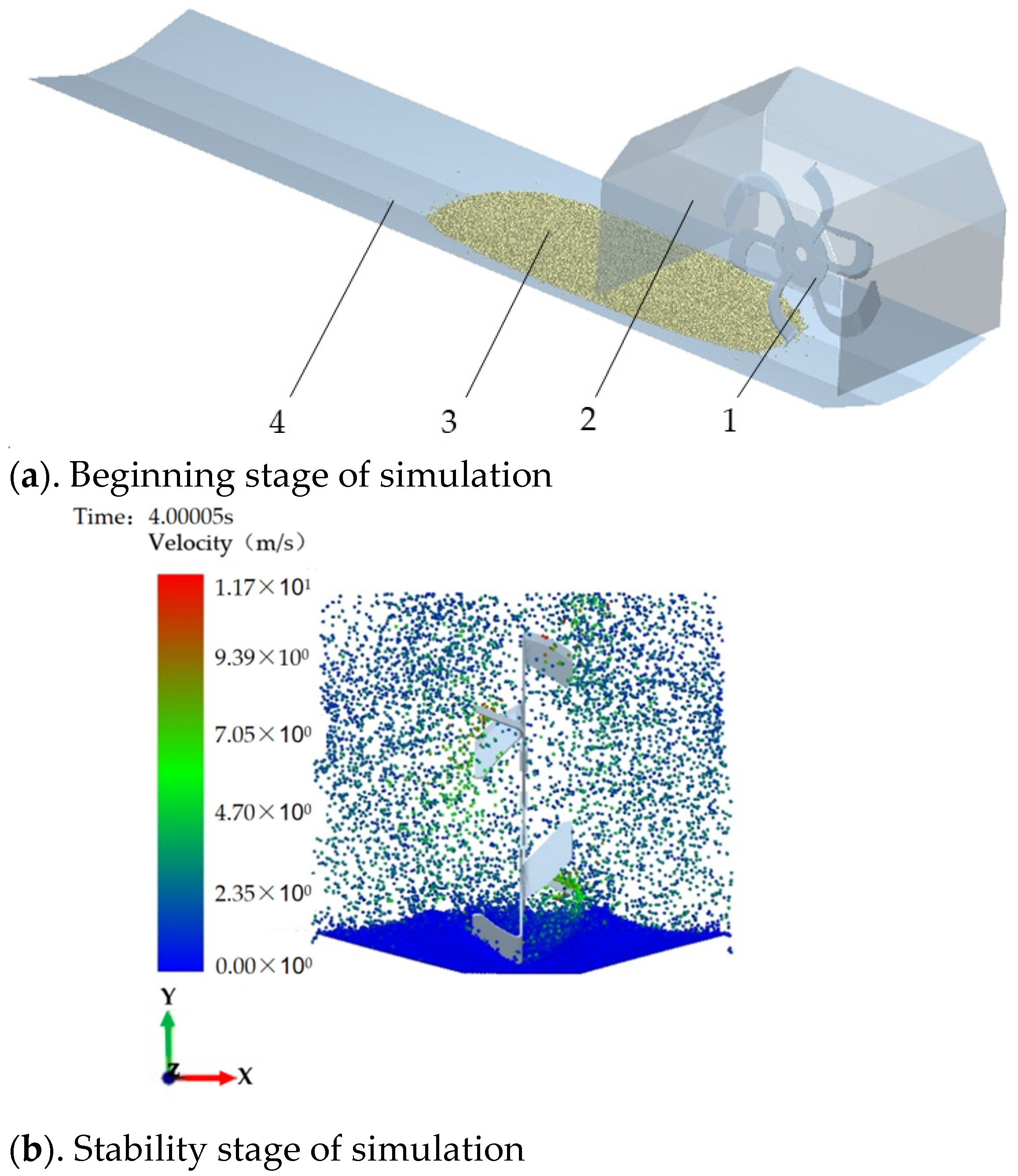
4.2. Simulation Process and Result Analysis

Before the simulation, SolidWorks was used to conduct 1:1 modeling of the rotary tillage knife and soil reflection device, then the modeling was imported into EDEM after completion. At the beginning of the simulation, the rotary tillage knife begins to operate at one end of the soil-covering belt of the seedlings, as shown in Figure 18a. The forward speed of the rotary tillage knife was set as 0.2 m/s, the rotational speed was set to be 300 r/min, and the total time was set to be 9 s. The stability stage of simulation is shown in Figure 18b.
Figure 19a shows the soil-covering effect of the seedbed after simulation of rotary tillage. It can be seen from the simulation results that the rotary tillage covering device can backfill the soil into the ridge furrow and form the ridge. At the same time, the covering width (Figure 19b) can reach 350 mm. This is due to the reflection positioning of soil particles by the soil reflection device. The actual throwing range of the rotary tiller blade is more than 350 mm. The specific results are determined by the throwing direction and lateral velocity of the soil particles. The covering thickness (Figure 19c) can reach 71 mm at the thickest point. The seedbed presents the shape of an arc, and the soil particles on both sides of the seedbed are fewer. The main reason for this situation is that when the rotary tillage knife operates at high speed, the higher the speed in the direction of the seedling head, the stronger the reflection effect on the soil particles on both sides of the soil reflection device and the higher the impact of soil particles on the seedling bed during the process of falling back, resulting in a certain inclination angle of the seedling bed. During the subsequent process of burying seedlings with film edge soil covering, the seedling head burial and film edge soil-covering devices not only cover the film edge with soil but also complete the secondary soil covering of seedling heads, thereby meeting the requirements for the thickness of the seedlings’ soil covering.

5. Field Experiment

5.1. Purpose and Scheme Design of the Experiment

In order to check the working performance of the whole machine in the actual operation process, a field working performance test of the prototype was carried out in the test field of Weiyuan County, Dingxi City in March 2023 (Figure 20).
Before the field test, a rototiller crushed soil in the field to ensure that the terrain of the test area was flat. The soil in the field was yellow loam soil, the moisture content was 12.2%, the surface temperature was 6.7 °C, and the wind speed of the air near the surface was 1.29 m/s. The tractor used to drive the machine was a Dongfeng 554 tractor with climbing gear, 6-month-old Codonopsis seedlings were selected as the test seedlings, and the average diameter of the seedling head was 3 mm and the average length was 110 mm. The seedlings were tied with a slip-knot before the test, and the average number in each bundle was 175.
Performance tests were carried out with the forward speed of the tractor at 0.1 m/s, 0.15 m/s, and 0.2 m/s, respectively, and the output speed of the rotary tillage knife was 400 r/min. At each forward speed, the depth of the rotary tillage knife was fixed at 220 mm and the target seedling spacing was set at 4.4 cm. Three groups of tests were carried out at each operating speed. Referring to JB/T 10291-2013 [29] “Standard for dryland planting machinery”, the standard deviation of seedling spacing, coefficient of variation of seedling spacing, qualified rate of film side outcrop, qualified rate of planting depth, and planting posture were selected to comprehensively evaluate the accuracy of seedling spacing and planting quality of the prototype.

5.2. Accuracy of Seedling Spacing

The intersection point between the head of a Codonopsis seedling and the seedbed is the planting point of the seedling, and the projection distance of the planting point of two adjacent Codonopsis seedlings on the edge of the film is the planting spacing of the two Codonopsis seedlings. The planting distance Xi of each group of Codonopsis seedlings was measured, the accuracy of the seedling spacing was evaluated by the coefficient of variation, and the test results of the accuracy of seedling spacing are shown in Table 4.

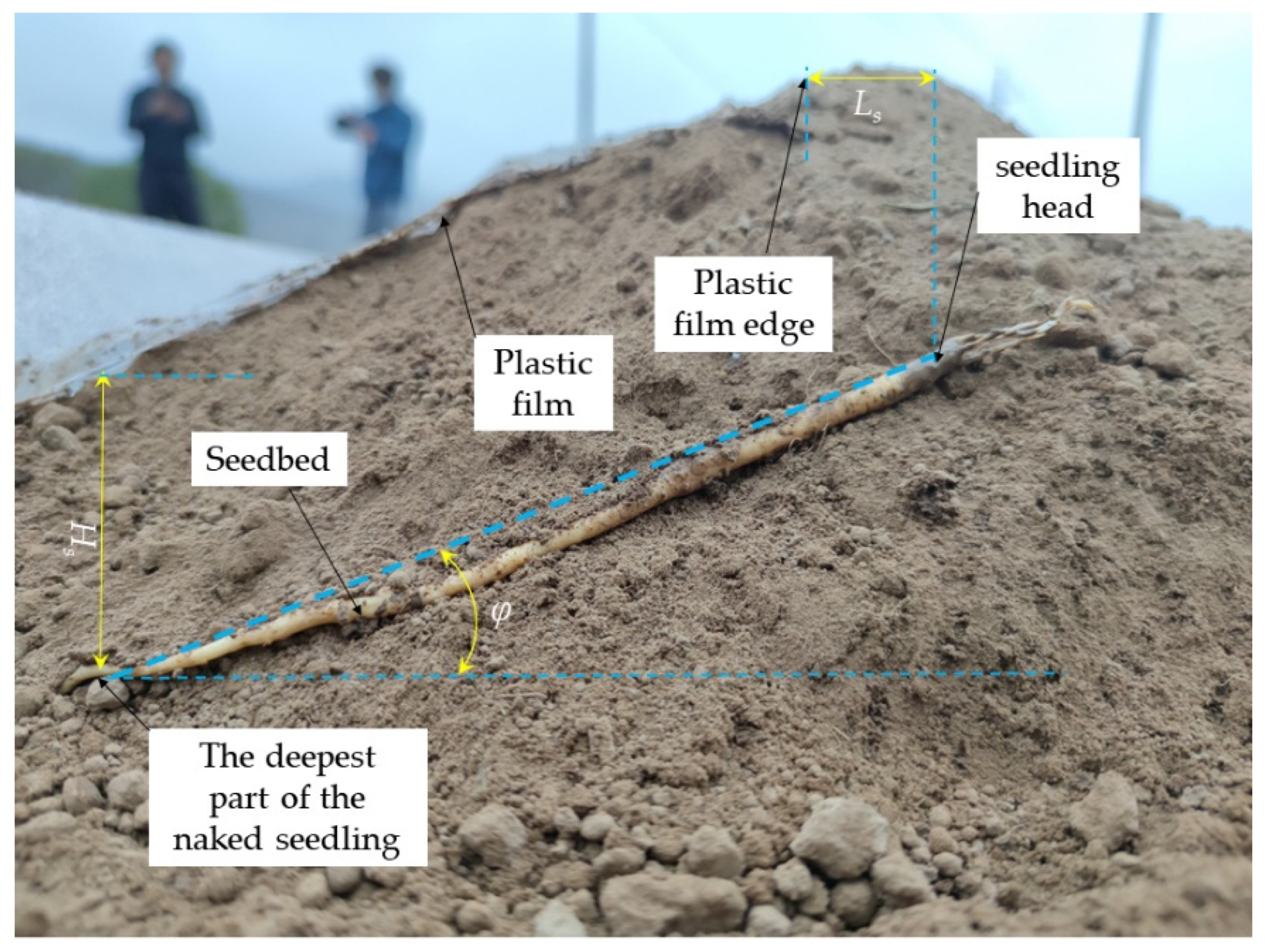
5.3. Qualified Rate of Planting Depth, Planting Posture, and Film Side Outcrop

In order to measure the planting depth, planting posture, and outcrop distance on the membrane side of Codonopsis seedlings, before data collection, the horizontal distance Ls between the seedling head and the membrane edge after the membrane edge points vertically downward and the covering soil is removed was set as the measurement standard for the membrane side outcrop. The angle between the naked seedling and the horizontal plane was set as φ , and the distance between the deepest part of the naked seedling and the ridge surface was measured as H s (Figure 21).
According to the agronomic requirements of Codonopsis seedling transplanting, when the planting depth meets the standard 4   cm H s 8   cm , the planting depth can be regarded as qualified. When the angle between the naked seedling and the horizontal plane meets the standard 10 ° φ 20 ° , the planting posture can be regarded as qualified. When the horizontal distance between the seedling head and the membrane edge meets the standard 3   cm L s 5   cm , film side outcrop can be regarded as qualified. Supposing the total number of planted seedlings is Nt, the number of seedlings which meet the standard of planting depth is Ns, the number of seedlings meeting the standard of planting posture is Nz, and the number of seedlings which meet the standard of film side outcrop is Nl, then the calculation method of the qualified rate of planting depth Ps, the qualified rate of planting posture Pz, and the qualified rate of the film side outcrop Pl are, respectively, as follows:
P s = N s N t × 100 %
P z = N z N t × 100 %
P l = N l N t × 100 %
The test results obtained from the above formula are shown in Table 5.

5.4. Discussion of Test Results

In the process of the field test, the prototype could complete the operation process of seedbed preparation, seedling casting, rotary tillage soil covering, film covering outcrop, and film edge soil covering at one time when the target seedling spacing is set at 4.4 cm and the forward speed is 0.1, 0.15, and 0.2 m/s. When the machine moves forward at the speed of 0.1 m/s, the average planting spacing was 4.56 cm, the average variation coefficient of planting spacing was 0.08%, the average qualified rate of planting depth was 95.83%, the average qualified rate of planting posture was 94.17%, and the average qualified rate of film side outcrop was 93.33%. When the forward speed of the machine was 0.15 m/s, the average planting spacing was 4.87 cm, the average variation coefficient of planting spacing was 0.19%, the average qualified rate of planting depth was 92.5%, the average qualified rate of planting posture was 89.17%, and the average qualified rate of film side outcrop was 88.33%. When the forward speed of the machine was 0.2 m/s, the average planting spacing was 4.78 cm, the average variation coefficient of planting spacing was 0.40%, the average qualified rate of planting depth was 90.83%, the average qualified rate of planting posture was 84.17%, and the average qualified rate of film side outcrop was 84.17%. While the machine moves forward at the speed of 0.1, 0.15, or 0.2 m/s, referring to JB/T 10291-2013 [29] “Standard for dryland planting machinery”, the variation coefficient of planting spacing is less than or equal to 20%, the qualified rate of planting depth is greater than or equal to 75%, and the variation coefficient of planting spacing and qualified rate of planting depth both reach the standard requirements. The variation coefficient of planting spacing becomes larger with the increase in forward speed, and the qualified rate of planting depth decreases with the increase in forward speed, indicating that the speed of prototype operation has a great influence on the seedling spacing and planting depth. There are no relevant standard requirements about the qualified rate of planting posture and film side outcrop at present, so the qualified rate cannot be evaluated. It can be seen from the test results that the qualified rate of planting posture and film side outcrop are greatly affected by the speed of the machine and decrease with the increase in operation speed. It can also be concluded from the field test results that when the forward speed of the prototype is 0.1 m/s, the operating performance is better than that of 0.15 m/s and 0.2 m/s.

6. Conclusions

(1) According to the agronomic requirements of Codonopsis membrane side outcrop cultivation, a kind of combined machine for transplanting Codonopsis outcrop onto a micro ridge covered with film was designed. The field capacity of the entire machine has reached 0.45–0.65 hm2·h−1, When the number of workers is equal, it has 4–5 times the field capacity of manual work. The operation process of the entire machine is simple, reducing labor intensity and improving production efficiency. After the emergence of Codonopsis seedlings, water injection irrigation under the film can be carried out at both ends of the ridges and ditches, which solves the problem that the Codondopsis cannot be irrigated under the requirements of dryland film-mulched transplanting.
(2) This study sets the relevant parameters of the core components of the whole machine and studies the working mechanism. The installation angle of the reshaper has been determined to be 60°, the angle between the seedling-throwing direction and the horizontal plane of the seedling-throwing device is 60°, and the seedling-throwing height is 80 mm. A rotary tillage knife is used to cut the soil and cover the seedlings with soil. Using EDEM to conduct motion simulation of the rotary tillage and soil-covering operation process of the equipment, the simulation results show that when the forward speed of the rotary tillage knife is set to 0.2 m/s and the rotational speed is set to 300 r/min, the requirements for the thickness and width of the soil cover for the seedlings can be met.
(3) The field test results showed that the variation coefficient of plant spacing and the qualified rate of planting depth reached the standard requirements when the target plant spacing was 4.4 cm and the working speed was 0.1, 0.15, and 0.2 m/s. When the working speed of the prototype increased, the plant spacing and planting depth were greatly affected. The qualified rate of the planting posture and the film outcrop were greatly affected by the working speed of the whole machine and decreased with the increase in the working speed. When the machine moved forward at a speed of 0.1 m/s, the average variation coefficient of planting spacing was 0.08%, the average qualified rate of planting depth was 95.83%, the average qualified rate of planting posture was 94.17%, and the average qualified rate of film side outcrop was 93.33%. The working performance was better than that of 0.15 m/s and 0.2 m/s.

Author Contributions

Conceptualization, W.S. and Z.Z.; software, B.S. and Z.Z.; investigation, B.S., W.S., Z.Z., L.Z., H.L., H.Z., X.L., H.W. and P.L.; resources, W.S.; writing—original draft preparation, B.S.; writing—review and editing, W.S., Z.Z., H.Z., H.L. and B.S.; supervision, L.Z., X.L., H.Z., H.W., P.L. and H.L.; project administration, W.S.; funding acquisition, W.S. All authors have read and agreed to the published version of the manuscript.

Funding

This work was supported by the Modern Silk Road Cold and Drought Agricultural Technology Support Project (GSLK-2022-12), Gansu Province Agricultural Machinery Equipment Shortcomings Action Project (njyf2023-13-1), and the National Key R&D Plan (2021YFD1100506).

Institutional Review Board Statement

Not applicable.

Informed Consent Statement

Not applicable.

Data Availability Statement

The data presented in this study are available on request from the corresponding author.

Acknowledgments

We fully appreciate the editors and all anonymous reviewers for their constructive comments on this manuscript.

Conflicts of Interest

The authors declare no conflict of interest.

References

  1. Fang, H. Establishment of Codonopsis industrial technology innovation strategic alliance in Gansu Province. Daily Ganws.com—Gansu Economic Daily, 23 October 2018. [Google Scholar]
  2. Liu, D.; Gong, Y.; Zhang, X.; Yu, Q.; Zhang, X.; Chen, X.; Wang, Y. EDEM Simulation Study on the Performance of a Mechanized Ditching Device for Codonopsis Planting. Agriculture 2022, 12, 1238. [Google Scholar]
  3. Chang, Y. High-yield Cultivation Technology of Codonopsis in Tongwei County. J. Gansu Agric. 2014, 16, 68–70. [Google Scholar]
  4. Iqbal, M.Z.; Islam, M.N.; Chowdhury, M.; Islam, S.; Park, T.; Kim, Y.J.; Chung, S.O. Working Speed Analysis of the Gear-driven Dibbling Mechanism of a 2.6 kw Walking-type Automatic Pepper Transplanter. Machines 2021, 9, 6. [Google Scholar] [CrossRef]
  5. Han, L.; Mao, H.; Hu, J.; Kumi, F. Development of a Riding-type Fully Automatic Transplanter for Vegetable Plug Seedlings. Span. J. Agric. Res. 2019, 17, e0205. [Google Scholar] [CrossRef]
  6. Jin, X.; Li, D.; Ma, H.; Ji, J.; Zhao, K.; Pang, J. Development of Single Row Automatic Transplanting Device for Potted Vegetable Seedlings. Int. J. Agric. Biol. Eng. 2018, 11, 67–75. [Google Scholar] [CrossRef] [Green Version]
  7. Yan, W.; Hu, M.; Li, K.; Wang, J.; Zhang, W. Design and Experiment of Horizontal Transplanter for Sweet Potato Seedlings. Agriculture 2022, 12, 675. [Google Scholar] [CrossRef]
  8. Xu, G.; Liu, H.; Farman, A.C.; Fang, H.; Jian, S.; He, T. Design and Experiment of Tilting Transplanting Mechanism on Salvia Miltiorrhiza Film. J. Agric. Mach. 2019, 50, 78–89+101. [Google Scholar]
  9. Wu, G.; An, X.; Yan, B.; Li, L.; He, Y.; Meng, Z. Design and Test Based on Pretreatment of Seedlings with Bare Sweet Potato Seedling Transplanting Machine. J. Agric. Mach. 2022, 53, 99–109. Available online: https://kns.cnki.net/kcms/detail/11.1964.S.20220818.0828.002.html (accessed on 25 October 2022).
  10. Wang, X.; Song, J.; Liu, C.; Dong, X.; Wang, J.; Zhang, C. Design and Experiment of Liquorice Tilting Transplanting Ditcher. J. Agric. Mach. 2016, 32, 16–23. [Google Scholar]
  11. Na, M.; Teng, L.; Zhou, K.; Wang, J.; Dong, X.; Zhou, M. Optimization Design and Experiment of Planting Mechanism of Double Operation Machine for Pot seedling Transplanting in dryland. J. Agric. Mach. 2022, 53, 67–73. [Google Scholar]
  12. Liu, D.; Gong, Y.; Zhang, X.; Chen, X.; Wang, G.; Zhang, X. Design and Experiment of Dry-Farming Cantaloupe Transplanter under Water. Agriculture 2022, 12, 796. [Google Scholar] [CrossRef]
  13. Wang, J.; Tang, H.; Wang, J.; Lin, N.; Huang, H.; Zhao, Y. Design and Experiment of 1DSZ-350 Suspended Paddy Field Single-side Rotary Tillage Suppression and Construction Machine. J. Agric. Eng. 2017, 33, 25–37. [Google Scholar]
  14. Shi, L.; Yang, X.; Zhao, W.; Sun, W.; Li, R.; Sun, B. Design and Experiment of a Combined Potato Sowing Machine with Throwing and Lifting Interfilm Soil-covering. J. Agric. Mach. 2018, 49, 129–137. [Google Scholar]
  15. Sun, W.; Liu, X.; Shi, L.; Zhang, H.; Liu, Q.; Wu, J. Soil Covering Characteristics of Scraper Lift Belt Film Covering Device. J. Mech. Eng. 2016, 52, 38–45. [Google Scholar] [CrossRef]
  16. Niu, C.; Xu, L.; Duan, Z.; Liu, X.; Ma, S.; Yuan, Q.; Wang, S.; Yuan, X.; Zeng, J.; Chen, C. Development of Hedge Frame Type Grape Soil Removal and Cold-proof Cloth Recovery Machine in Winter. J. Agric. Eng. 2020, 36, 50–58. [Google Scholar]
  17. Ma, S.; Xu, L.; Xing, J.; Yuan, Q.; Yu, C.; Duan, Z.; Chen, C.; Zeng, J. Development of Rotary Vane Removal Machine for Grape Vine Soil Burial. J. Agric. Eng. 2018, 34, 1–10. [Google Scholar]
  18. Yang, Q.; He, M.; Shi, L.; Shi, A.; Zhao, X. Study on Interaction between Wine-grape Scraper and Cold-proof Soil. J. Agric. Eng. 2021, 37, 21–30. [Google Scholar]
  19. Hu, M.; Zhang, W.; Ji, Y.; Qi, B.; Xia, Q.; Li, K. Influence of Hole Tray Seedling with Biodegradable Pot Transplanting on Pepper Growth Character. J. Chin. Agric. Mech. 2020, 41, 57–62. [Google Scholar] [CrossRef]
  20. Hu, L.; Wang, B.; Wang, G.; Yu, Z.; You, Z.; Hu, Z.; Wang, B.; Gao, X. Design and Experiment of 2ZGF-2 Compound Planting Machine for Sweet potato. J. Agric. Eng. 2016, 32, 8–16. [Google Scholar]
  21. Yuan, T.; Wang, D.; Wen, Y.; Zhu, S.; Chen, Y.; Tan, Y. Design and Experiment of Air-blown Vibration Compound Seedling Taking Mechanism of Vegetable Transplanter. J. Chin. Agric. Mech. 2019, 50, 80–87. [Google Scholar]
  22. Fang, H.; Ji, C.; Chandio, F.A.; Guo, J.; Zhang, Q.; Arslan, C. Analysis of Soil Motion Behavior During Rotary Tillage Based on Discrete Element Method. J. Agric. Mach. 2016, 47, 22–28. [Google Scholar]
  23. Tan, H.; Xu, L.; Ma, S.; Niu, C.; Yan, C.; Shen, C. Design and Test of Scraper Organic Fertilizer Strip Mixed with the Rotary Tillage Machinery of Fertilizer. J. Agric. Mach. 2022, 53, 163–175. Available online: http://kns.cnki.net/kcms/detail/11.1964.s.20220928.1749.008.html (accessed on 14 October 2022).
  24. Liao, Q.; Du, W.; Zhang, Q.; Lin, J.; Chen, Z.; Zhang, J. Design and Test of Cigar Tobacco Adjustable Seedbed Ridging Membrane Machine. J. Agric. Mach. 2022, 1–13. Available online: http://kns.cnki.net/kcms/detail/11.1964.s.20221108.1209.006.html (accessed on 17 December 2022).
  25. Sun, J.; Liu, Q.; Luo, P.; Yang, F.; Liu, Z.; Wang, Z. Study on Soil Erosion Law of Slope Contour Tilling by Tractor in Mountain. J. Agric. Mach. 2022, 53, 44–56. [Google Scholar]
  26. Chen, B.; Chen, X.; Chen, X.; Zhu, J.; Yu, Q.; Liao, Y.; Liu, Y. Design and Test of Crawler Self-propelled Rotary Tillage Strawberry Ridging Fertilizer Compounding Machine. J. Chin. Agric. Mech. 2022, 43, 55–60, 85. [Google Scholar] [CrossRef]
  27. Zheng, K.; Li, Y.; Xia, J.; Liu, G.; Cheng, J.; Kang, Q. Design and Experiment of Axial Soil Levelling Cutter Roller with Gradual Spiral Lifting Angle for Furrow Rotiller. J. Agric. Mach. 2021, 52, 63–73. [Google Scholar]
  28. Dai, F.; Zhang, S.; Song, X.; Zhao, W.; Ma, H.; Zhang, F. Design and Experiment of a Combined Plastic-film Mulching Machine on Double Ridges and Double Width. J. Agric. Mach. 2020, 51, 108–117. [Google Scholar]
  29. JB/T 10291-2013; Dry Land Planting Machinery. Ministry of Industry and Information Technology of the People’s Republic of China: Beijing, China, 2013.
Figure 1. Schematic diagram of the cultivation mode of Codonopsis outcrop on micro ridge covered with plastic film. 1. Ridge body. 2. Head of Codonopsis. 3. Root of Codonopsis. 4. Outcrop area on membrane side. 5. Ridge soil-covering belt. 6. Mulch. 7. Film edge. 8. Rain-collecting surface.
Applsci 13 09149 g001
Figure 2. Overall structure diagram. 1. Hanging device. 2. Seat. 3. Seeding box. 4. Seedling-casting device. 5. Frame. 6. Seedling head burial and film edge soil-covering device. 7. Spreading film roll. 8. Film-hanging frame. 9. Soil reflection device. 10. Gearbox. 11. Rotary tillage soil-covering device. 12. Ground wheel. 13. Power transmission device. 14. Seedbed preparation device. 15. Ditching shovel.
Applsci 13 09149 g002
Figure 3. Structural Diagram of Seedbed Preparation Device. 1. Frame. 2. Adjustment lever of shaper. 3. Connection lever of shaper. 4. Adjusting rod of crushing roll. 5. Shaper. 6. Crushing roll. 7. Adjusting bolt. 8. Adjusting nut.
Applsci 13 09149 g003
Figure 4. Schematic Diagram of Operation Process of Seedbed Preparation Device. 1. Seedling soil-covering belt. 2. Seedbed. 3. Ridge body. 4. Non-working area. 5. Seedbed preparation device.
Applsci 13 09149 g004
Figure 6. Spatial force analysis at the moment of soil particle slipping under the action of shaper.
Applsci 13 09149 g006
Figure 7. Structure of seedling-casting device. 1. Seedling protection plate. 2. Cylindrical pin. 3. Connecting block. 4. Fixed pin. 5. Seedling separation plate. 6. Conveyor belt. 7. Driving shaft of seedling-casting device. 8. Driven shaft I. 9. Driven shaft II.
Applsci 13 09149 g007
Figure 8. Analysis of seedling movement in the air. 1. Seedling protection plate. 2. Conveyor belt. 3. Cross-section of seedbed. 4. Seedbed. 5. Seedling soil-covering belt. 6. Driving shaft of seedling-casting device. 7. Seedling.
Applsci 13 09149 g008aApplsci 13 09149 g008b
Figure 9. Schematic diagram of rotary tillage knife arrangement.
Applsci 13 09149 g009
Figure 10. Schematic diagram of rotary tillage knife throwing soil. 1. Seedlings. 2. Seedling soil-covering belt. 3. Ridges. 4. Soil particles. 5. Seedbed. 6. Rotary tillage knife.
Applsci 13 09149 g010
Figure 11. Area of soil cut by rotary tillage blade.
Applsci 13 09149 g011
Figure 12. Spatial force of a single soil particle.
Applsci 13 09149 g012
Figure 15. Structural diagram of film-covering device. 1. Adjusting rod of film-spreading roll. 2. Film-hanging rod. 3. Plastic film. 4. Mulching area on furrow. 5. Rain-collecting surface. 6. Seedlings. 7. Film side outcrop. 8. Film-spreading roll. 9. Connecting rod of film-spreading roll. 10. Connecting frame of film-hanging rod. 11. Frame.
Applsci 13 09149 g015
Figure 16. Schematic diagram of transmission system of combined machine. 1. Coupling. 2. Trenching shovel. 3. Seedbed preparation device. 4. Driving shaft of seedling-casting device. 5. Driven shaft I. 6. Ground wheel. 7. Seedling-casting device. 8. Driven shaft II. 9. Chain drive. 10. Gearbox. 11. Cutter shaft. 12. Rotary tillage soil-cutting set. 13. Hanging frame. 14. Film-spreading roller. 15. Soil-covering disk.
Applsci 13 09149 g016
Figure 17. Structure diagram of rotary tillage knife.
Applsci 13 09149 g017
Figure 18. Simulation process. 1. Rotary tillage knife. 2 Soil reflection device. 3. Soil particles. 4 V-shaped seedbed.
Applsci 13 09149 g018
Figure 19. End of simulation.
Applsci 13 09149 g019
Figure 20. Effect of Field Experiment.
Applsci 13 09149 g020
Figure 21. Schematic diagram of measurement of planting posture.
Applsci 13 09149 g021
Table 1. Manual transplanting operation procedure of Codonopsis seedlings.
NoProcessPictureRequirements
1Seedbed preparationApplsci 13 09149 i001The seedbed is tilted 10° to 20°
2Setting seedlingsApplsci 13 09149 i002The heads of the seedlings are aligned and the spacing is 40~60 mm
3Covering the seedlings with soil (burying the seedlings)Applsci 13 09149 i003The thickness of covering soil is 40~80 mm, and the soil should be scattered evenly
4MulchingApplsci 13 09149 i004The distance between film edge and head of the seedlings is 0~40 mm
5Covering the membrane edge and seedlings with soilApplsci 13 09149 i005The operation process must ensure full coverage of the soil at the membrane edge and over the seedlings
Table 2. Main technical parameters of operating machine.
ParametersNumerical Values
Machine dimensions
(length × width × height)/(mm × mm × mm)
2297 × 2107 × 1655
Auxiliary power/kw44.1
Overall quality/kg512
Seedling placement methodManual seedling
placement
Seedling outcrop distance/mm0~40
Plant spacing/mm44
Field capacity/(hm2·h−1)0.45~0.65
Number of seeding rows4
Angle of inclined planting/°15
Covering thickness of seedlings/mm40~80
Number of plastic films2
The width of plastic film/mm620
Suspension modeThree-point
suspension
Table 3. Parameters of simulation model.
ProjectParametersNumerical Value
Soil particles, V-shaped seedbedsPoisson’s 0.4
ratio shear modulus/Pa1.0 × 106
Density/(kg.m−3)1364
Rotary tillage knifePoisson’s 0.28
ratio shear modulus/Pa3.5 × 1010
Density/(kg.m−3)7850
Soil particles–soil particles, seedbedsCoefficient of recovery 0.21
Coefficient of static friction0.68
Coefficient of dynamic friction0.27
Soil particles–rotary tillage knifeCoefficient of recovery0.54
Coefficient of static friction0.68
Coefficient of dynamic friction0.13
Table 4. Test results of seedling spacing accuracy.
NumberForward Speed (m/s)Average Seedling Spacing/cmStandard Deviation/cmCoefficient of Variation/%
10.104.540.400.09
20.104.570.410.09
30.104.560.310.07
40.154.850.880.18
50.154.910.860.17
60.154.841.020.21
70.204.901.730.35
80.204.802.160.45
90.204.651.890.41
Table 5. Results of planting test.
NumberForward Speed (m/s)Number of PlantsNumber of Qualified Plants for Planting DepthNumber of Qualified Plants for Planting PostureNumber of Qualified Plants for Membrane Side OutcropQualified Rate of Planting Depth/%Qualified Rate of Planting Posture/%Qualified Rate of Film Side Outcrop/%
10.14038363695.0090.0090.00
20.14038393895.0097.5095.00
30.14039383897.5095.0095.00
40.154037373692.5092.5090.00
50.154038353595.0087.5087.50
60.154036353590.0087.5087.50
70.24036353290.0087.5080.00
80.24036343590.0085.0087.50
90.24037323492.5080.0085.00
Disclaimer/Publisher’s Note: The statements, opinions and data contained in all publications are solely those of the individual author(s) and contributor(s) and not of MDPI and/or the editor(s). MDPI and/or the editor(s) disclaim responsibility for any injury to people or property resulting from any ideas, methods, instructions or products referred to in the content.

