Abstract
In order to increase industrial production quality and efficiency, it is essential to understand how the aeration and no-aeration condition affects liquid and solid material mixing in the stirred tank. Due to complicated shear flows, the related mass-transfer mechanism confronts numerous difficulties. This paper put forward an improved computational fluid dynamics and discrete element method (CFD–DEM) modeling approach to explore the effect mechanism of aeration conditions on liquid–solid material mixing. Firstly, a mass-transfer dynamic model is set up with a volume of fluid and piecewise linear interface construction (VOF–PLIC) coupling strategy to explore flow modes and vorticity evolution trends under aeration control. Then, a self-developed interphase coupling interface is utilized to modify the coupling force and porosity of the porous media model in the DEM module, and random dispersion properties of the particle phase under non-aeration and aeration are obtained. Results show that the aeration and flow-blocking components transform fluid tangential speeds into axial and radial speeds, which can improve the material mixing quality and efficiency. The mixed flow field can reach a greater turbulent process under the impeller rotation, making the particles have an intensive disorder and complex flow patterns. The enhanced motion efficiency of the vortex clusters encourages their nesting courses and improves cross-scale mixed transport. It can serve as some reference for the three-phase flow mixing mechanism, vorticity distribution law, and particle motion solution and has a general significance for battery homogeneous mixing, biopharmaceutical processes, and chemical process extraction.
1. Introduction
The multiphase stirring reactor has been applied in biochemical, architectural engineering, and metallurgy courses. In liquid–solid systems, the solid particles denote the dispersed phase, and the mixing, dispersion, and transfer between the various phases are highly difficult [1,2,3,4]. To achieve good interphase mass transport efficiency and accelerate the reaction process, the reactor must ensure particle suspensions and uniform dispersion. The discrete phase holdup distribution, vorticity distribution, and particle suspension effect in the reactor are concerned with the reactor type, flow pattern, and operating parameters, which can effectively reflect mixing courses. Hence, in order to obtain the best design and engineering scale-up, it is important to explore the multiphase mixing effect mechanism, flow transport laws, and dynamic control techniques.
Numerous variables, including the kind of stirring paddle, the mode of operation, and the phase composition, impact the multiphase mixing process [5,6,7]. To fulfill the goal of mass transfer, the material must be well mixed and disseminated, which is accomplished in the mixing tank by the rotating impeller and provides energy to the fluid in the paddle region. This powerful three-dimensional flow subsequently encourages the general flow of the whole tank [8,9]. Several innovative actuators have been developed to enhance the power and mass-transfer performance of conventional paddle types in order to increase the efficacy of gas–liquid mass transfer. However, mixing solid phases, such as solid catalysts and biomass, frequently occurs in conjunction with the gas–liquid stirring process. Adding a solid phase further increases the intricacy of the mass-transfer process. It poses significant problems to the dynamic properties of mass transfer and the real-time evolution of the three-phase flow pattern.
A number of techniques have been investigated for measuring the internal characteristic parameters of the chemical reactor. Macroscopic properties of three-phase flow reactors, such as characteristic speed and power consumption, can be measured using established techniques [10,11,12]. However, it is challenging to measure the local phase holdup distribution using dispersible phases. With the advancement of computational fluid mechanics theory, the CFD method has demonstrated tremendous promise in assisting in the most effective design of reactors. It has steadily grown to be a crucial tool for industrializing and scaling up reactors [13,14,15]. Micale used the Euler–Euler multi-fluid model to predict and simulate two-phase systems with flow-blocking components and found that the numerical technique can forecast the formation course of transparent liquid layers [16]. Ochieng studied solid suspension in a baffled tank by the CFD method and found that the transient simulation method could better predict solid suspension than the steady-state method [17]. Wang combined the theory of two-fluid dynamics to study particle flow behaviors and found that the numerical method forecasts velocity and particle distribution at different altitudes [18]. Gu used the classical Euler–Euler method and standard turbulence model to study suspension process properties. As the impeller rotation speed rises, the increasing liquid viscosity keeps particles in suspension [19]. The internal fluid dynamics features of the reactor under various configurations and operating situations can be modeled and predicted using the specifics of the macroscopic flow and microscopic turbulence characteristics in the stirred tank.
From the above literature, current research focuses on rotating velocity, particle behaviors, and two-phase flows. The effects of the aeration condition on the liquid–solid material mixing with a single-layer impeller are absent. Due to the lack of local characteristic experimental parameters related to gas–liquid–solid mixed course, the numerical modeling and solving methods of three-phase mixing containers regarding cross-scale transfer mechanism need further exploration.
To address the above problems, an improved CFD–DEM coupling modeling method oriented to three-phase mixed material transfer is presented. Firstly, a fluid–solid coupling model is built with a VOF–PLIC–DEM method. The bidirectional coupling calculation processes of fluid and particles are realized to restore the particle state by the self-developed interphase coupling interface. The effects of the aeration condition on the liquid–solid material mixing with a single-layer impeller are explored to obtain the material mixing mechanism and flow patterns.
2. Mixing Process Numerical Model
2.1. Flow-Field Mathematical Model
The mixed flow field involves many phenomena, including energy exchange, multiphase coupling, and material transfer [20,21,22]. The multiphase VOF model can be appropriate to track interphase interfaces and obtain better numerical precision. The control equations can be described as follows [23,24,25]:
where u describes the fluid velocity, Fpf denotes the reactive force, p is the pressure, Fst is the surface tension, μ is the dynamic viscosity, ρl denotes the fluid density, and β is the void ratio. The interface can be acquired by the volume fraction [26,27,28]:
where Sαq is the source term, βq denotes the volume fraction, mpq and mqp denote the mass transport from phase p to q and phase q to p, respectively, vq denotes the phase velocity, and ρq is the phase density. The above equations are solved separately for each phase, not only for the principal phase but also satisfying the following constraints: .
The mixed flow course has typical rotation and shear flow field characteristics. The piecewise linear interface construction (PLIC) approach takes on good restoration effects on swirling and shear velocity fields, and constructed interfaces have higher precision [29,30,31,32]. The PLIC approach can solve interface shapes and properly trace the mixing course.
The gas–liquid interface appears in the inner junction of an element (i, j). The normal vector n can be defined as the grid center, and the vector n is described as:
It is assumed that n = (nx, ny) is perpendicular to interfaces, and the t linear equation of interphase interfaces is
In Equation (5), b denotes the distance from point B to an interface, and the fluid zone can be the shadow part zone.
According to the b sum Eij obtained, only a definite line segment is observed, and an interface is determined.
The mixed flows are a complex turbulent mechanics problem. The basic characteristic of turbulent flow is the randomness of fluid microcluster motion, which not only has lateral pulsation but also has an opposite motion relative to the total motion of the fluid. The renormalization group RNG (k-ε) model focuses on higher Reynolds number issues, which are appropriate for intensive swirling flows involving rapid strains and cross-scale vortices, and are suitable for simulating the mixed flow in the stirred tank. The transport and dissipation equations of turbulence energy can be expressed as follows [33,34,35]:
where αk and αε denote reciprocals of the effective Prandtl numbers, YM is the effect of the total dissipation rate, and Gk and Gb are the turbulence kinetic energy terms.
2.2. Particle Mathematical Model
The discrete element method (DEM) can compute contact forces and motions. Particle phases can be regarded as discrete phases, which are closer to reality than other methods and can better restore the real motion of the particle [36,37]. The contact torque and governing equations are obtained [38,39,40]:
where Ii denotes the inertia moment, represents the angular displacement, Fpf,i is the interaction force, xi is the particle displacement, Fc,ij denotes the interphase contact force, mi is the particle mass, and Tt,ij and Tr,ij are the tangential and rolling friction moments, respectively.
To obtain the interphase contact effects, a soft sphere model can be used to compute the particle contact process. The particle softball model of particle contact provides springs, dampers, couplers, and sliders between particles and walls. The particle is regarded as an ideal rigid body, and the precise motion trajectory of the particle is calculated by using the DEM theory. Combined with the softball contact model, the collision contact processes between particles and walls can be obtained more accurately.
2.3. Fluid–Solid Coupling Solution Method
A porous model-based fluid–solid coupling method is presented to obtain interphase effects. The computer equation can be described as follows:
where εps,i is the particle volume in a control element.
The VOF–DEM computation flow chart is described in Figure 1. As the boundary condition is initial, the governing equations and turbulent energy equations can be solved. Then, the DEM module computes the particle motion equations and updates the particle’s characteristic information. As the coupling solution is convergence, the flow field performs the next step. If not, the porous model is utilized to compute interphase effects and continue flow calculation. It is possible to realize this two-way coupling and communicate data until convergence.
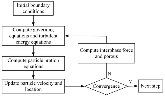
Figure 1.
Fluid–solid coupling flow chart.
3. Numerical Calculation of the Three-Phase Model
3.1. Physical Geometry and Meshing
The mixed model selected is a semi-circular bottom container with a baffle plate. The model mainly includes a mixing impeller, mixing shaft, mixing tank wall, inlet and outlet, and four uniform baffles. The structure is described in Figure 2, and the following physical characteristics can be obtained: diameter W = 200 mm, installation height D = 93 mm, paddle length L = 45 mm, inclination angle 45°, liquid level height hl = W, mixing shaft diameter d1 = 14 mm, height H = 3T/2, width W = T/10, air inlet diameter d2 = 14 mm, impeller diameter Y = W/2, height ha = 4 mm, baffle height hb = 11W/10, and width W/10.
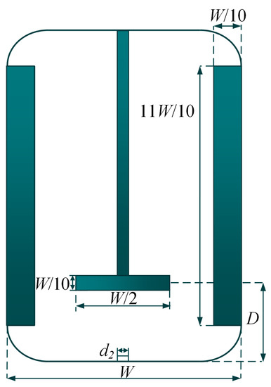
Figure 2.
Hybrid space structure diagram.
During mesh partitioning, proper resolution, smoothness, low skew, and a proper number of meshes should be considered [41,42]. The mesh must be fine in places with enormous pressure, velocity, and temperature gradient. To calculate efficiently in the area of small velocity and temperature gradient, there is no significant change in the flow behavior to be captured, and such an area does not need to be divided into a better mesh. Since the calculation cost is proportional to the element numbers, it is best to fully consider the flow-field properties, select appropriate grid sizes, and reduce unnecessary grid numbers. Here, the tetrahedral meshes are utilized to divide the fluid field domain and set up the three-phase dynamic model (Figure 3).
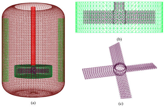
Figure 3.
Mesh division of the numerical model. (a) Vessel zone mesh. (b) Rotating zone mesh. (c) Paddle mesh.
The fluid region includes the vessel zone and rotating zone. The gradient variation in the strong shear zone is the biggest due to the huge variable gradient of the rotating region, particularly the mixed impeller. The partial grid division course should be refined so the grid scales of the vessel and rotating zones are 7 mm and 5 mm, respectively, and the total meshes are 527,890.
3.2. Boundary and Initial Conditions
The vessel wall denotes non-slipping condition, the bottom represents the aerated pipe, the top of reaction containers represents the pressure outlet boundary condition, and the speed entrance can be set. The impeller rotation model should be carefully solved in hybrid simulation. The multiple reference frame model can simulate mixing tanks with baffles and tanks, saving calculation resources and accurately meeting most scenarios [43,44,45]. Due to the simulation of an unsteady process and complex phase change, pressure implicit with splitting operators can be adopted. The pressure staggering option method can be utilized to avoid internal pressures from changing rapidly and high swirling flow.
In EDEM software, a softball contact model should be utilized to solve the particle impact course, and the elastic coefficient and damping coefficient establish the collision contact model to calculate the collision contact course. The physical parameters can be listed in Table 1. A user-defined function interphase interface is designed to achieve bidirectional fluid–solid coupling calculations. Default sample point parameters, momentum subluxation factor, volume subluxation factor, and heat source relaxation factor remain unchanged. In the particle factory, 10,000 spherical particles are randomly generated. To ensure computational stability and continuity, the particle scale should be smaller than the smallest grid size, and the element size should meet calculating accuracies.

Table 1.
Fluid and granule medium characteristics.
4. Results and Discussion
4.1. Particle Evolution Regularities in the Three-Phase Mixing Process
The physical space of gas, liquid, and solid is a complex turbulent environment, and the existence of flow baffle elements causes turbulent flows to be a disorder at the rotating speed. It will be further investigated and compared to how different aeration settings affect fluid flow and solid particle suspension in the mixed area in order to acquire the fluid–solid multiphase coupling and interphase mass-transfer characteristics.
Figure 4 shows particle velocity distribution in the three-phase mixing course. In Figure 4a, the particle is located at the bottom of the container, and the particle takes on the concentrating forms. The particles are sucked under impeller rotating effects. The impeller rotation increases shear energies and fluid axial speeds. In Figure 4b, the particles are in contact with the impeller and diffused to the container wall and baffle since the rotating effect. The particles in the impeller center have a large speed value in Figure 4c, and the particle speed is concentrated at 0.75 m/s–1.0 m/s. Still, the particle speed at the bottom of the impeller can be concentrated at 0 m/s–0.5 m/s. In Figure 4d, the impeller disperses particles and slows down local particles. Under the action of the rotating impeller, some of the particles rise to the free liquid level while others are stopped by the baffle and fall to the container bottom. The particles may be completely mixed, and the fluid field may be in extremely nonlinear turbulence.
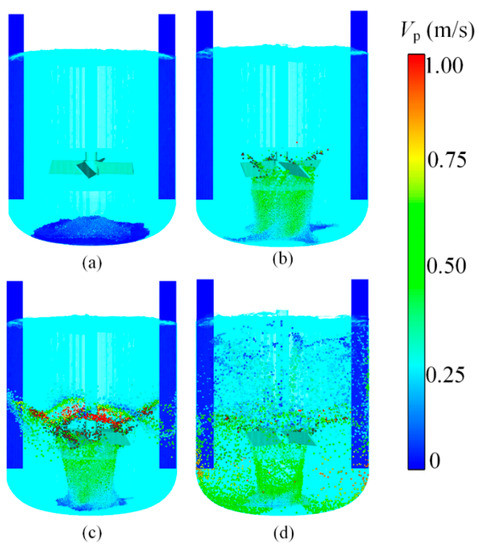
Figure 4.
Particle velocity distributions in the three-phase mixing process. (a) Initial state. (b) Particle rise. (c) Particle dispersion. (d) Particle mixing.
The radial velocity distribution can be obtained to investigate particle evolution features (Figure 5). This section is centrally located above the aeration port and represents the radial distribution of particles at the mixing space. Particle speed distribution in the initial state is uniform in Figure 5a, and there is no large value. At this time, the particles can be mainly influenced by gravity and vertical upward suction, showing a central convergence state. In Figure 5b, the particles move upward under the effect of impeller rotation, and the local particles reach a high-velocity peak. Many particles show uniform velocity variation characteristics. Figure 5c shows no significant change in particle velocity, and only one particle has a mutation peak. In Figure 5d, after the mixed flow field reaches a completely turbulent state, the velocity amplitude of the particles fluctuates greatly, a large number of particles have random velocity values, and the velocity distribution is nonlinear. It can be seen from the above characteristics that after full mixing, the disorder and randomness of particle motion in the entire flow field become more complex, and the material mixing efficiency will inevitably increase.
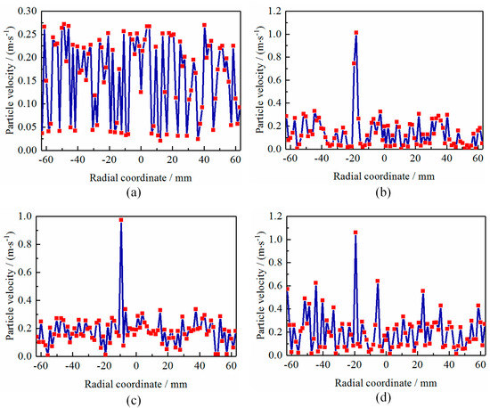
Figure 5.
Particle velocity curves in the three-phase mixing process. (a) Initial state. (b) Particle rise. (c) Particle dispersion. (d) Particle mixing.
Based on the above, the energy evolution trends of particles in this cross-section are obtained, as shown in Figure 6. The total energy of particles has a high randomness in the evolution process. In Figure 6a, the particle capacity varies within a small fluctuation range, wherein the particles are mainly affected by kinetic energies generated by impeller rotating effects. In Figure 6b, when the flow field begins to disturb, the particle energy changes obviously, showing more random energy pulses. As particles diffuse to the mixed flow field, the energy value of particles increases slightly, as shown in Figure 6c. The velocity of most particles is concentrated in the range of 4 J~5 J, and only a few particles have an energy value of 7 J. In Figure 6d, after the flow field is fully mixed, the total energy of particles does not change significantly, but the randomness is enhanced. The phenomenon shows that the mixed flow field can achieve a higher turbulent process under impeller rotation, which makes particles take on a higher disorder and complex flow patterns.
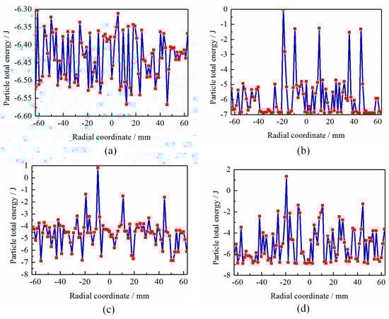
Figure 6.
Particle energy curves in the three-phase mixing process. (a) Initial state. (b) Particle rise. (c) Particle dispersion. (d) Particle mixing.
4.2. Evolution Characteristics in the Three-Phase Mixing Process
The velocity distributions under non-aerated and aerated conditions are shown in Figure 7. The fluid around the impeller has a large velocity value. A local circulating flow is formed under the paddle rotation and baffle action (Figure 7a). When the mixed fluid fields are inflated in Figure 7b, the mixed fluid is lifted from the bottom by the rotation of the blade and sent through the blade by strong shear forces at high speed. The impeller rotation effect causes a portion of the fluid to descend and then rise again, creating a circulating flow in the lower portion.
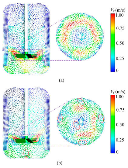
Figure 7.
Velocity distributions of mixed flow field under non-aerated and aerated conditions. (a) Non-aerated. (b) Aerated.
From the figure, the loop flows in the left and right parts are different. Under the action of the baffle, many local turbulent vortices are formed in the mixed flow field in the aerated state, which improves the evolution disorder of flow patterns. The above phenomenon shows that the gas filling control directly affects the three-phase mixing course and can increase the chaotic evolution trend to enhance mass-transfer efficiencies and material mixing qualities.
The vorticity cloud diagrams are obtained to investigate the influences of inflation conditions on three-phase mixed courses, as shown in Figure 8. As the mixing container is inflated, the vorticity distribution becomes complex, as shown in Figure 8a. In impeller rotation and baffle obstruction, the vorticity of turbulent vortices accumulates on both sides of the mixing vessel, as shown in Figure 8b,c. In the upper part of the impeller, the vorticity value is small, and the fluid field appears to have a lower vorticity zone and presents an asymmetric state (Figure 8c). In Figure 8d, the impeller has a larger vorticity value. When the inflation rate of the mixing vessel is large, the turbulent field has higher upper impulse energy, and the vorticity value in the inflation region is the largest, which produces intensive disturbances to mixing systems. The above phenomena illustrate that the dynamic control method of aeration increases the material mixing process of the turbulent field and causes complex polymerization and dissipation phenomenon of local turbulent vortices. It improves the quality and efficiency of the three-phase mixing process to a certain extent.
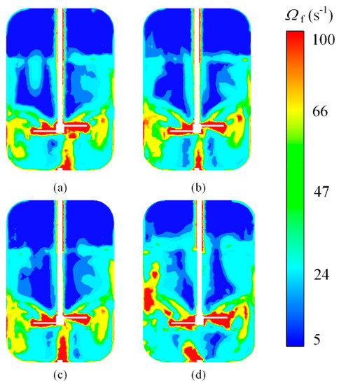
Figure 8.
Vorticity distributions of flow field under aeration conditions. (a) Initial state. (b) Particle rise. (c) Particle dispersion. (d) Particle mixing.
4.3. Particle Dispersion Effect
The relative standard deviation (RSD) can be introduced to characterize particle dispersion effects, as shown in Figure 9. The RSD of particle numbers in multiple sampling zones should be adopted as an evaluation index. Due to a particle being deposited at the container bottom, the RSD value is large in the initial state, and the particle distribution is uneven. The RSD curve has an upward trend. As the stirring course continues, particles reach impellers and disperse to various regions, and the RSD curves show rapid downward trends. Then it oscillates in a small range to a quasi-steady state. The RSD curve without aeration takes on decreasing trends, and lower RSD values appear. At this time, the particle state is steady, oscillation amplitudes with aeration conditions are large, and dispersion effects are the best. Inflation increases the mixed instability and nonlinear turbulent motion. The above phenomena illustrate that aeration control will improve particle suspension effects and enhance distribution uniformity.
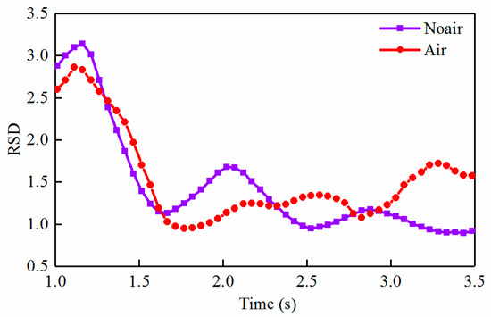
Figure 9.
Changes in the RSD with time under air and no-air working conditions.
5. Conclusions
The three-phase mixing transport is a complex dynamic phenomenon, and numerical modeling of fluid–solid two-way coupling in the shear region is challenging. Here, a three-phase flow modeling method is proposed to investigate the effect mechanisms of inflation on the particle suspension features. Relevant conclusions are as follows:
- (1).
- Based on a VOF–PLIC approach, a three-phase mass-transfer model can be conducted to obtain flow modes and vorticity evolution trends under the aeration condition. Many local turbulent vortices are formed in the aerated state, and the baffle makes flow patterns appear as disordered features. The aeration increases the material mixing efficiency and causes polymerization and dissipation phenomenon of the local turbulent vortices.
- (2).
- According to the UDF interphase interface, the flow field can be coupled with the DEM model for bidirectional calculation. The mixed flow field under impeller rotation can achieve a relatively high turbulent process, some particles rise to the free liquid level, and some particles are interrupted by the baffle and fall to the bottom of the container. The particles take on a higher disorder, and the flow pattern of particles becomes complicated.
- (3).
- Under the aeration control, the motion efficiency of vortex groups can be improved, which promotes the nesting course of vortex groups across scales and raises mixed transport with cross-scale vortices. It improves material mixing effects inside the reaction vessel and has guiding significance for engineering applications such as the chemical industry and lithium batteries.
Author Contributions
Conceptualization, J.C. and M.G.; writing—original draft preparation, J.C.; funding acquisition, J.C. and M.G.; article identification, screening, retrieval, selection, and analysis, J.C., L.L. and M.G.; supervision, J.C.; generation of tables and figures, J.C.; review and editing, J.C. and M.G.; formal analysis and investigation, J.C. and M.G.; supervision, J.C. All authors have read and agreed to the published version of the manuscript.
Funding
This work was supported in part by the Open Research Project of Robot Technology and Intelligent Manufacturing Equipment Engineering Laboratory of Jiangsu Province under Grant SDGC2140.
Institutional Review Board Statement
Not applicable.
Informed Consent Statement
Not applicable.
Data Availability Statement
Not applicable.
Conflicts of Interest
The authors declare no conflict of interest.
References
- Kulkarni, S.S.; Janssen, P.H.M.; Dickhoff, B.H.K. The impact of material chemistry and morphology on attrition behavior of excipients during high shear blending. Powder Technol. 2023, 427, 118694. [Google Scholar] [CrossRef]
- Jin, Z.; He, D.; Wei, Z. Intelligent fault diagnosis of train axle box bearing based on parameter optimization VMD and improved DBN. Eng. Appl. Artif. Intell. 2022, 110, 104713. [Google Scholar] [CrossRef]
- Li, Q.; Xiang, P.; Li, L. Phosphorus mining activities alter endophytic bacterial communities and metabolic functions of surrounding vegetables and crops. Plant Soil 2023, in press. [Google Scholar] [CrossRef]
- Li, L.; Tan, Y.F.; Xu, W.X.; Ni, Y.S.; Yang, J.G.; Tan, D.P. Fluid-induced transport dynamics and vibration patterns of multiphase vortex in the critical transition states. Int. J. Mech. Sci. 2023, 252, 108376. [Google Scholar] [CrossRef]
- Wei, Z.X.; He, D.Q.; Jin, Z.Z.; Liu, B.; Shan, S.; Chen, Y.J.; Miao, J. Density-based affinity propagation tensor clustering for intelligent fault diagnosis of train bogie bearing. IEEE Trans. Intell. Transp. Syst. 2023, 24, 6053–6064. [Google Scholar] [CrossRef]
- Zheng, G.A.; Gu, Z.H.; Xu, W.X.; Li, Q.H.; Tan, Y.F.; Wang, C.Y.; Li, L. Gravitational surface vortex formation and suppression control: A review from hydrodynamic characteristics. Processes 2023, 11, 42. [Google Scholar] [CrossRef]
- Chen, J.T.; Ge, M.; Li, L.; Zheng, G. Material transport and flow pattern characteristics of gas–liquid–solid mixed flows. Processes 2023, 11, 2254. [Google Scholar] [CrossRef]
- Bao, Z.; Wang, X.; Wang, Q.; Zou, L.; Peng, L.; Li, L.; Tu, W.; Li, Q. A novel method of domestication combined with ARTP to improve the reduction ability of Bacillus velezensis to Cr(VI). J. Environ. Chem. Eng. 2023, 11, 109091. [Google Scholar] [CrossRef]
- Bao, Z.; Feng, H.; Tu, W.; Li, L.; Li, Q. Method and mechanism of chromium removal from soil: A systematic review. Environ. Sci. Pollut. Res. Int. 2022, 29, 35501–35517. [Google Scholar] [CrossRef]
- Li, L.; Yang, Y.S.; Xu, W.X.; Lu, B.; Gu, Z.H.; Yang, J.G.; Tan, D.P. Advances in the multiphase vortex-induced vibration detection method and its vital technology for sustainable industrial production. Appl. Sci. 2022, 12, 8538. [Google Scholar] [CrossRef]
- Li, Q.; Luo, Y.; Sha, A. Analysis of synonymous codon usage patterns in mitochondrial genomes of nine Amanita species. Front. Microbiol. 2023, 14, 1134228. [Google Scholar] [CrossRef]
- Hosseini, S.; Patel, D.; Ein-Mozaffari, F. Study of solid-liquid mixing in agitated tanks through computational fluid dynamics modeling. Ind. Eng. Chem. Res. 2010, 49, 4426–4435. [Google Scholar] [CrossRef]
- Liu, S.; Lu, Y.; Li, J. A blockchain-based interactive approach between digital twin-based manufacturing systems. Comput. Ind. Eng. 2023, 175, 108827. [Google Scholar] [CrossRef]
- Liu, S.; Lu, Y.; Shen, X.; Bao, J. A digital thread-driven distributed collaboration mechanism between digital twin manufacturing units. J. Manuf. Syst. 2023, 68, 145–159. [Google Scholar] [CrossRef]
- Li, L.; Xu, W.X.; Tan, Y.F.; Yang, Y.S.; Yang, J.G.; Tan, D.P. Fluid-induced vibration evolution mechanism of multiphase free sink vortex and the multi-source vibration sensing method. Mech. Syst. Signal Process. 2023, 189, 110058. [Google Scholar] [CrossRef]
- Micale, G.; Grisafi, F.; Rizzuti, L. CFD simulation of particle suspension height in stirred vessels. Chem. Eng. Res. Des. 2004, 82, 1204–1213. [Google Scholar] [CrossRef]
- Ochieng, A.; Lewis, A.E. CFD simulation of solids off-bottom suspension and cloud height. Hydrometallurgy 2006, 82, 1–12. [Google Scholar] [CrossRef]
- Wang, S.; Jiang, X.; Wang, R. Numerical simulation of flow behavior of particles in a liquid-solid stirred vessel with baffles. Adv. Powder Technol. 2017, 28, 1611–1624. [Google Scholar] [CrossRef]
- Gu, D.; Liu, Z.; Xie, Z. Numerical simulation of solid-liquid suspension in a stirred tank with a dual punched rigid-flexible impeller. Adv. Powder Technol. 2017, 28, 2723–2734. [Google Scholar] [CrossRef]
- Liu, S.; Bao, J.; Zheng, P. A review of digital twin-driven machining: From digitization to intellectualization. J. Manuf. Syst. 2023, 67, 361–378. [Google Scholar] [CrossRef]
- Li, L.; Lu, B.; Xu, W.X.; Gu, Z.H.; Yang, Y.S.; Tan, D.P. Mechanism of multiphase coupling transport evolution of free sink vortex. Acta Phys. Sin. 2023, 72, 034702. [Google Scholar] [CrossRef]
- Yin, Z.C.; Lu, J.F.; Li, L.; Wang, T.; Wang, R.H.; Fan, X.H.; Lin, H.K.; Huang, Y.S.; Tan, D.P. Optimized Scheme for Accelerating the Slagging Reaction and Slag-Metal-Gas Emulsification in a Basic Oxygen Furnace. Appl. Sci. 2020, 10, 5101. [Google Scholar] [CrossRef]
- Chen, J.C.; Han, P.C.; Zhang, Y.; You, T.; Zheng, P.Y. Scheduling energy consumption-constrained workflows in heterogeneous multi-processor embedded systems. J. Syst. Archit. 2023, 142, 102938. [Google Scholar] [CrossRef]
- Tan, Y.F.; Ni, Y.S.; Wu, J.F.; Li, L.; Tan, D.P. Machinability evolution of gas-liquid-solid three-phase rotary abrasive flow finishing. Int. J. Adv. Manuf. Technol. 2023, in press. [Google Scholar] [CrossRef]
- Li, L.; Gu, Z.H.; Xu, W.X.; Tan, Y.F.; Fan, X.H.; Tan, D.P. Mixing mass transfer mechanism and dynamic control of gas-liquid-solid multiphase flow based on VOF-DEM coupling. Energy 2023, 272, 127015. [Google Scholar] [CrossRef]
- Chen, J.C.; Zhang, Y.; Wu, L.W.; You, T.; Ning, N. An adaptive clustering-based algorithm for automatic path planning of heterogeneous UAVs. IEEE Trans. Intell. Transp. Syst. 2022, 23, 16842–16953. [Google Scholar] [CrossRef]
- Chen, J.C.; He, Y.; Zhang, Y. Energy-aware scheduling for dependent tasks in heterogeneous multiprocessor systems. J. Syst. Archit. 2022, 129, 102598. [Google Scholar] [CrossRef]
- Li, L.; Li, Q.H.; Ni, Y.S.; Wang, C.Y.; Tan, Y.F.; Tan, D.P. Critical penetrating vibration evolution behaviors of the gas-liquid coupled vortex flow. Energy 2023, in press.
- Wang, T.; Wang, C.Y.; Yin, Y.X.; Zhang, Y.K.; Li, L.; Tan, D.P. Analytical approach for nonlinear vibration response of the thin cylindrical shell with a straight crack. Nonlinear Dyn. 2023, 111, 10957–10980. [Google Scholar] [CrossRef]
- Chen, J.C.; Ling, F.Y.; Zhang, Y. Coverage path planning of heterogeneous unmanned aerial vehicles based on ant colony system. Swarm Evol. Comput. 2022, 69, 101005. [Google Scholar] [CrossRef]
- Zheng, G.A.; Shi, J.L.; Li, L.; Li, Q.H.; Gu, Z.H.; Xu, W.X.; Lu, B. Fluid-solid coupling-based vibration generation mechanism of the multiphase vortex. Processes 2023, 11, 568. [Google Scholar] [CrossRef]
- Gu, Y.H.; Zheng, G.A. Dynamic evolution characteristics of the gear meshing lubrication for vehicle transmission system. Processes 2023, 11, 561. [Google Scholar] [CrossRef]
- Singh, N.K.; Premachandran, B. Coupled level set and volume of fluid method on unstructured grids for the direct numerical simulations of two-phase flows including phase change. Int. J. Heat Mass Transf. 2018, 122, 182–203. [Google Scholar] [CrossRef]
- Li, L.; Lu, J.F.; Fang, H.; Yin, Z.C.; Wang, T.; Wang, R.H.; Fan, X.H.; Zhao, L.J.; Tan, D.P.; Wan, Y.H. Lattice Boltzmann method for fluid-thermal systems: Status, hotspots, trends and outlook. IEEE Access 2020, 8, 27649–27675. [Google Scholar] [CrossRef]
- Chen, J.C.; Du, C.L.; Zhang, Y.; Han, P.C.; Wei, W. A clustering-based coverage path planning method for autonomous heterogeneous UAVs. IEEE Trans. Intell. Transp. Syst. 2022, 23, 25546–25556. [Google Scholar] [CrossRef]
- Li, L.; Qi, H.; Yin, Z.C.; Li, D.F.; Zhu, Z.L.; Tangwarodomnukun, V.; Tan, D.P. Investigation on the multiphase sink vortex Ekman pumping effects by CFD-DEM coupling method. Powder Technol. 2020, 360, 462–480. [Google Scholar] [CrossRef]
- Katircioglu-Bayel, D. Effective role of grinding aids in the dry grinding performance of calcite. Powder Technol. 2023, 426, 118675. [Google Scholar] [CrossRef]
- Li, L.; Tan, D.P.; Wang, T.; Yin, Z.C.; Fan, X.H.; Wang, R.H. Multiphase coupling mechanism of free surface vortex and the vibration-based sensing method. Energy 2021, 216, 119136. [Google Scholar] [CrossRef]
- Li, Q.; Xiang, P.; Zhang, T.; Wu, Q.; Bao, Z.; Tu, W.; Li, L.; Zhao, C. The effect of phosphate mining activities on rhizosphere bacterial communities of surrounding vegetables and crops. Sci. Total Environ. 2022, 821, 153479. [Google Scholar] [CrossRef] [PubMed]
- Liu, H. Study on UAV Parallel Planning System for Transmission Line Project Acceptance Under the Background of Industry 5.0. IEEE Trans. Ind. Inform. 2022, 18, 5537–5546. [Google Scholar] [CrossRef]
- Dong, Y.L.; Guo, W.; Zha, F.S.; Liu, Y.Z.; Chen, C.; Sun, L.N. A Vision-Based Two-Stage Framework for Inferring Physical Properties of the Terrain. Appl. Sci. 2020, 10, 6473. [Google Scholar] [CrossRef]
- Liu, H.; Chen, N.; Pan, N.; Sun, Y.; An, Y.; Pan, D. UAV Stocktaking Task-Planning for Industrial Warehouses Based on the Improved Hybrid Differential Evolution Algorithm. IEEE Trans. Ind. Inform. 2022, 18, 582–591. [Google Scholar] [CrossRef]
- Lin, L.; Tan, D.P.; Yin, Z.C.; Wang, T.; Fan, X.H.; Wang, R.H. Investigation on the multiphase vortex and its fluid-solid vibration characters for sustainability production. Renew. Energy 2021, 175, 887–909. [Google Scholar]
- Tan, D.P.; Li, L.; Li, D.F.; Zhu, Y.L.; Zheng, S. Ekman boundary layer mass transfer mechanism of free sink vortex. Int. J. Heat Mass Transf. 2020, 150, 119250. [Google Scholar] [CrossRef]
- Lu, J.F.; Wang, T.; Li, L.; Yin, Z.C. Dynamic Characteristics and Wall Effects of Bubble Bursting in Gas-Liquid-Solid Three-Phase Particle Flow. Processes 2020, 8, 760. [Google Scholar] [CrossRef]
Disclaimer/Publisher’s Note: The statements, opinions and data contained in all publications are solely those of the individual author(s) and contributor(s) and not of MDPI and/or the editor(s). MDPI and/or the editor(s) disclaim responsibility for any injury to people or property resulting from any ideas, methods, instructions or products referred to in the content. |
© 2023 by the authors. Licensee MDPI, Basel, Switzerland. This article is an open access article distributed under the terms and conditions of the Creative Commons Attribution (CC BY) license (https://creativecommons.org/licenses/by/4.0/).