Abstract
Qualitative and quantitative assessments evaluate the structural vulnerability of liquid storage tanks. Liquid storage tanks are typically constructed and operated in areas with hard soils to minimize confining influences. However, many of these critical structures are in coastal areas with soft soils. The research conducted in this study entails the utilization of the finite element method accurately model the seismic behavior of a semi-buried concrete tank under various conditions, including changing water levels and soil properties. The study examines fluid–structure and soil–structure interactions through dynamic analyses of the rectangular semi-buried tank and comparing its different parameters. It also identifies sensitive areas where there is a probability of liquid leakage in storage tanks. The modeling is compared with the qualitative evaluation in the Japanese vibration capability diagnosis table. The results show that the tensile stress in the wall adjacent to the expansion joint is greater than the corresponding stress in the wall in all cases. In the dynamic analyses of the soil types, the pressure on the surface increases with increasing water height. A comparison of the quantitative and qualitative evaluation results shows the possible leakage of the tank in soft soil in the expansion joint.
1. Introduction
Liquid storage tanks are a part of the municipal utility system in many cities. In several large cities, the rapid increase in water demand from all available resources has doubled the need to use these storage facilities [1]. In addition, managing supply and consumption peaks is another fundamental reason for using these tanks. According to the Tehran Water and Sewerage Organization Information Centre, 265 tanks with a capacity of 24.2 million cubic meters of potable water store and balance the water pressure in the distribution networks of Tehran province, Iran [2]. Like any structure, liquid storage tanks carry specific risks associated with their operation. For instance, in the USA, there is a problem of leaking tanks and contamination of drinking water; nationwide, about 542,000 underground storage tanks (USTs) are used to store petroleum and its derivatives or hazardous materials such as toxic materials containing dangerous chemicals and heavy metals known to be carcinogenic [3].
This type of structure can be classified based on various parameters and indicators. For example, these tanks can be buried or semi-buried. The factors affecting the determination of soil resources related to buried and semi-buried tanks include climatic conditions, topography, soil limitations, the soil slope, and the soil layer’s materials [3]. In terms of geometry, these tanks are usually classified as cylindrical and rectangular cubes [4]. In general, these tanks can be divided into four construction materials: steel, concrete, wood, and excavated material (farm dams). Tanks can also be classified according to their substance, such as petroleum and chemicals or hazardous wastes from industrial or nuclear power plants [5].
In recent years, water consumption has increased with the population growth in cities. Therefore, the demand for these tanks has also increased. According to a report by the Japan International Cooperation Organization (JICA), most of the damage from a possible earthquake in Tehran is caused by the Ray fault [6]. A significant portion of the cost of urban water supply projects is related to the construction of these tanks. Improper operation leads to water intrusion and fires and can cause irreparable environmental damage. Without a safe water supply, uncontrolled fires following a major earthquake can cause more damage than the earthquake itself, as demonstrated by the historic 1906 San Francisco earthquake [7]. Therefore, these structures must function wholly and safely after an earthquake [8]. Two main factors must be considered in designing an earthquake-resistant structure: (i) the characteristics of the earthquake forces and (ii) the dynamic properties of the structure. The characteristics of an earthquake include the frequency, maximum acceleration, and duration of the earthquake. Essentially, any structure resting on the ground is affected by six components of ground motion during an earthquake, including two lateral components, one vertical component, and three torsional components about the coordinate axes of the structure [8].
The shear forces and bending anchorages occur due to the hydrodynamic pressure produced by seismic activity. As a result of this hydrodynamic pressure, hoop stresses in the tank shell can lead to irreparable accidents if they are not adequately estimated during tank design. There are several methods for estimating the pressures generated in earthquake-prone tanks, one of which is Houser’s method [4]. In recent decades, many scientists have become interested in the hydrodynamic pressure of water and its effects on the structure during an earthquake [9,10,11]. Consequently, the response of vertical fluid reservoirs to earthquakes has been the subject of several studies on fluid–structure interaction [8], and the study of fluid reservoirs remains fundamental to earthquake engineering, e.g., Ruiz and Garcia [12], Kangda [13], and others. With the development of numerical methods and computer technology, the finite element method has been increasingly used in dynamic analysis [14,15,16,17,18].
Many experimental, analytical, and theoretical studies have been carried out to describe the phenomenon of water fluctuations [19]. The most practical algorithm for analyzing hot-filled tanks under seismic or harmonic excitation involves some masses and springs to simulate the excitation and vibration modes of the fluid. The mechanical idea proposed by Housner showed promising results for simple methods [4]. Haroun extended this research to flexible tanks [20]. Lyvavglv [21] studied the dynamic behavior of rectangular liquid tanks’ soil/foundation. This simple and fast method represents the interaction of two Hounser masses for liquid and a cylindrical model for soil/foundation. The results show that decreasing soil hardness decreases displacement and soil shear forces. However, embedment, flexibility, and soil–structure interaction do not significantly affect displacement volatility [21]. An analytical method was presented for rectangular tanks to determine the hydrodynamic pressures by solving the classical equations of the streaming potential [22]. This software provides a complete and comprehensive study of the interaction of structure and fluid with a seismic analysis for irregular geometries of slopes and the application of seismic loading as an accelerometer and time history analysis [23].
In other research on the dynamic analysis of rectangular water storage tanks, Kim et al. [24,25] show a numerical solution method to obtain the dynamic responses of rectangular tanks under the influence of horizontal and vertical soil excitations. In addition, Chen et al. [26,27] have proposed an iterative solution method to calculate the hydrodynamic pressure on the walls of rectangular tanks, which can take into account the flexibility effect of the walls. Nicolici and Bilegan [28] used ANSYS modeling software to solve a three-dimensional problem of the interaction of water and structures with flexible walls using computational fluid dynamics (CFD) tools and finite element stress analysis. Jamalabadi studied sloshing in flexible tanks induced by an earthquake using a one-way coupling of the finite element model (FEM) and CFD techniques. He found that the elasticity of the walls increased impulsive pressure [29]. Veletsos and Tang [30] studied the effects of soil–structure interaction on ground-level cylindrical tanks. Livaoglu and Dogangun [31] studied elevated tanks and showed that soil–structure interaction is crucial in this tank type. Therefore, fluid–structure and structure–soil interaction studies with FEM interaction using 3D FEM are essential to evaluating rectangular tanks’ seismic behavior considering fluid–soil interaction.
In addition, liquid storage tanks are generally characterized by low fundamental periods. However, many of these critical structures are in coastal regions with soft soils. Therefore, the seismic behavior of the structure may be significantly different compared to hard soils [32]. Soils can be classified into two categories based on their moisture amount: saturated and unsaturated. The difference between these two types of soils is related to their interactions with water and their mechanical properties. The distinction between saturated and unsaturated soils is essential in various geotechnical and environmental engineering applications, as it impacts the behavior and response of soils under different conditions. Extensive research on the principles of unsaturated soil mechanics has been carried out by researchers in integrated analysis [33,34,35,36,37]. Based on this, ignoring the principles of unsaturated soil mechanics will solve less production consolidation analysis. Proper drainage should be provided inside the embankment to maintain unsaturated conditions and to ensure the stability of the embankment under heavy rain [36].
The results of a storage tank model can provide valuable insight into the behavior and performance of the tank [38]. These insights can help improve the design and safety of the tank, as well as minimize potential issues such as leaks, collapses, and other forms of damage. This information can be used to optimize the tank’s design, ensuring it is strong and resilient enough to withstand the forces it will encounter during its lifetime. The model’s results contribute to the overall understanding and improvement of storage tank design and performance, leading to safer, more reliable, and more efficient storage systems. They can help mechanical mechanism analysis identify potential failure modes and assess the tank structure’s critical loads and stress points [39].
This study introduces a novel approach to the dynamic analysis of rectangular semi-buried tanks, incorporating fluid–structure and soil interaction principles. By considering the interactions between the tank structure, the fluid inside, and the surrounding soil, this research aims to comprehensively understand the tank’s behavior during seismic events, contributing valuable insights to earthquake engineering. Unlike previous studies focusing on specific aspects of liquid storage tanks, this research emphasizes real-world application by investigating the vulnerability of storage tanks in earthquake-prone regions. The study addresses the potential risk of fluid leakage in tanks during seismic events, which can significantly affect public safety and environmental protection. Unlike past research that may have overlooked the role of expansion joints, this investigation compares the effects of expansion joints and walls on tank performance. The study aims to shed light on their contributions to the tank’s seismic behavior by conducting a detailed analysis of these factors using ANSYS 11 software.
Many previous studies on liquid storage tanks may have relied on simplified modeling techniques that neglect crucial aspects such as fluid–structure interaction and soil–structure interaction. Such oversimplified models might only partially represent the tank’s behavior under realistic seismic conditions. Some past research focused on specific tank geometries, such as cylindrical or tanks with fixed dimensions. This limited scope could hinder a comprehensive understanding of the effects of different tank geometries and configurations on seismic performance. Some earlier studies might have yet to consider the significance of expansion joints in the seismic response of tanks. The omission of expansion joints from the analysis could result in an incomplete assessment of the tank’s vulnerability to seismic forces.
By addressing these limitations and incorporating original approaches, the present study aims to fill the gaps in the existing literature and provide valuable insights into the seismic performance of rectangular semi-buried tanks, considering fluid–structure and soil–structure interaction and comparing the effects of expansion joints and walls.
2. Review of Tank Regulations and Codes
2.1. General Framework
Following the Chile (1960) and Alaska (1964) earthquakes, numerous research investigations have been carried out about the seismic examination of tanks that store liquids. Within this particular context, the subsequent two facets were examined:
- In evaluating the seismic forces acting on tanks, great attention should be paid to the effects of sloshing of the liquid and the flexibility of the walls;
- Tanks have lower ductility, absorb less energy, and have a more downward depreciable force than conventional buildings.
In most design codes, tanks under the second method are considered to have a higher earthquake coefficient than buildings. Among the codes that provide instructions for concrete tanks, the International Building Code (IBC) [40] and the American Concrete Institute Standard (ACI) [41] are the best known and are analyzed here. It should be noted that this study examines and compares their rules and regulations, similarities, differences, and respective limitations. Then, the design earthquake of the reservoir is evaluated along with the design forces of the buildings. These ratings help find out how the earthquake’s intensity compares to the building with the seismic force and provide a better fit for the tanks.
The regulations classify concrete underground water tanks as inflexible or limited in their ability to absorb energy. The International Building Code (IBC) [40] indicates that the base shear coefficient ratio between the tank and the building equals or exceeds 4. This ratio holds even for prolonged periods of rotation due to the restricted spectrum range within the tanks. Despite the low energy absorption and flexibility, liquid storage tanks highly resist seismic forces. Therefore, it is no surprise to observe significant disparities between the various types of storage tank repositories described across different codes and regulations. A comparative analysis shows that tanks with limited flexibility exhibit a significantly higher impulsive base shear coefficient, approximately 6–7 times greater than that observed in more flexible structures such as buildings. By contrast, the value above exhibits a range of 3 to 4 across all codes when applied to a tank with heightened flexibility.
2.2. International Building Code (IBC)
IBC [40] provides rules and regulations for non-residential buildings, including tanks. For buildings, the base shear of the earthquake (V) is provided by Equation (1):
where W is the effective weight of the earthquake, the coefficient of base shear (Cs) needs to meet the requirement of a minimum of two values derived from Equations (2) and (3).
V = Cs × W
Cs = SDS/(R/I)
Cs = SD1/(R/I) × T
SDS and SD1 are the design accelerations of the spectral response at short and 1-s periods, respectively. At the same time, I stands for the essential factor, R is the response change factor, and T is the fundamental building period.
In the IBC, an R = 8 is recommended for ductile buildings. For most buildings, the coefficient of significance is I = 1. The illustrated data in Figure 1 displays the varying base shear values about the time period.
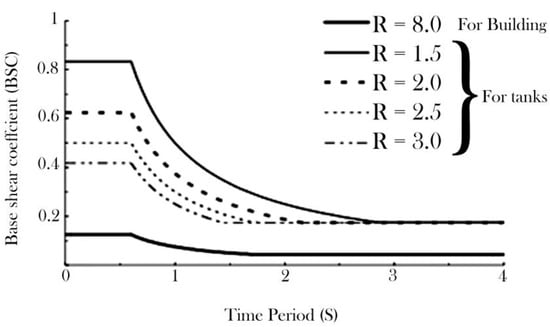
Figure 1.
The base shear coefficient variation with the natural period [42].
The critical parameter denoted by R is observed to possess lower values for tanks than buildings, owing to the limited flexibility inherent in the former. Table 1 presents a tabulated record of the various categories of concrete tanks delineated in the International Building Code (IBC) accompanied by their corresponding R-value. The graphical representation depicted in Figure 1 highlights the discernible observation that the base shear coefficient of a non-ductile building is notably more significant, ranging from three to seven times higher compared to its ductile counterpart. The numerical discrepancy is contingent upon the specific features and characteristics of the tank in question.

Table 1.
Classifications of ground tanks along with their corresponding R-values [40].
2.3. American Concrete Institute Standard (ACI)
The ACI [41] delineates a methodology for the seismic design of fluids within concrete tanks, including a thorough elucidation of impulsive and convective elements. The coefficient for base shear about the impulsive mode is determined using Equations (4), (5), or (6):
Csi = (0.6 × T0 (SDS/T0) + 0.4 × SDS)/1.4 × (R/I) for 0 < Ti < T0
Csi = SDS/1.4 × (R/I) for T0 < Ti < Ts
Csi = SD1/1.4 × (R/I) × Ti for Ti > Ts.
The variables SDD, SD1, R, and I are the same as described in IBC [40]. Ts = SD1/SDS, T0 = 0.2SDS/SD1, and Ti is the period of the impulsive mode. The CSC for all values of TC (the period of convective mode) is given by Equation (7):
CsC = 6 × I × SD1/TC2.
2.4. Analysis and Modeling in ACI
Reviewing various regulations revealed that ACI [41] is the most complete and straightforward method/analysis. In this regulation, the parameters of the mechanical model are calculated using the rigid reservoir model, while the flexibility of the reservoir is accounted for by calculating the impulsive period. Accurately determining hydrodynamic forces necessitates using adequate modeling and dynamic analysis techniques for fluid storage systems, which are intrinsically intricate [43,44,45,46]. It is known that the availability of mechanical reservoir models facilitates the analysis since these models simulate a reservoir-fluid system equivalent to a mass–spring system. These mechanical models are usually included in the design codes to estimate the seismic response of the reservoir. The present method incorporating the mass–spring technique contains various parameters for an exhaustive analysis. Several parameters affect the stability of reservoir walls. These include the pressure distribution resulting from the vertical displacement of the base during both lateral and vertical seismic modes, the repercussions of ground structure collision, and the maximum height of surface waves. Code ACI [41] uses the mechanical model of Houser [4] with modifications and examines the parameters of the mechanical model for rectangular tanks. The lateral seismic force’s intensity influences the impulsive mode’s duration. In contrast, the rotation period of the tank fluid system is dictated by the level of tank flexibility. ACI’s [41] formula for calculating impulsive mode period time is detailed in Table 2. Here, ‘K’ represents stiffness, ‘Ww’ denotes the equivalent weight of the tank wall, and ‘Wi’ stands for the equivalent weight of the prematurely stored fluid component.
Table 2.
The time period of impulsive mode [41].
In the prescription of ACI [36], the time period of the convective mode is determined by Equations (8) and (9), where L is the internal length of the rectangular tank, and HL is the depth of the stored water.
TC = (2π/λ) × √L
λ = √3.16 × g × tanh × (3.16 × (HL/L))
3. Numerical Modeling
3.1. Tank Definition and Modeling
According to the executed design drawings, an Iranian-built rectangular cube tank of 64 m in length, 32 m in width, and 6 m in height were modeled here (Figure 2). The water height in full mode was 5 m. The wall thickness of the tank was 0.4 m, which increased to 0.6 m in the inclined mode, and the wall of the tank was buried in the ground to a height of 2 m (Figure 3a). Consistent with Figure 2, this tank was located in a bottom basin with dimensions of three times the tank in each direction and a depth of 14 m. As shown in Figure 3, a large mesh decreases accuracy, while a small mesh increases the time and volume of calculations; therefore, the sensitivity of the mesh is critical.
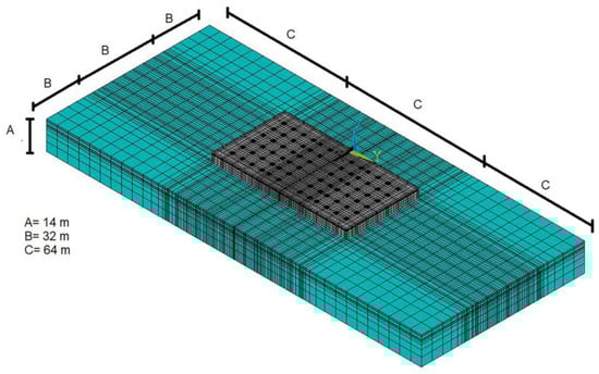
Figure 2.
A 3D model of the semi-buried rectangular tank.
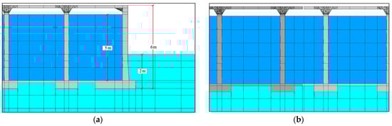
Figure 3.
(a) Cross-section of a storage tank and a demonstration of the meshing and interconnection of water–structure–soil elements in the model. (b) Cross-section of the expansion joint.
Wave propagation distortion during dynamic analysis might be noticeable, depending on the specific modeling circumstances. Two factors dictate the precision of wave transmission in numerical models: the range of frequencies within the input waves and the wave speed properties of the system. To faithfully capture wave propagation in a model, Liesmer et al. [42] and Derrick et al. [44] demonstrated that the size of each component (Δl) needs to be less than about a tenth to an eighth of the wavelength of the highest frequency component of the input wave, noted as Δl ≤ λ/10, where λ signifies the wavelength of the highest frequency part. During this research, the earthquake’s wavelength in the soil was established using an earthquake wave frequency of 7.5 Hz input into the software and the soil’s shear modulus. The result was a maximum element length of approximately 5 m for the soil’s mesh within the model.
Sections of the finite element geometry of the model are shown in Figure 2 and Figure 3. As can be seen in these figures, the mesh size increased in sensitive areas of the model, namely at the tank-support connection and where compressive forces were applied. This study presents a three-dimensional model of a 10,000 m3 tank. It should be noted that this model consists of two tanks, each with a capacity of 5000 m3, and an expansion joint that has been considered in the model (Figure 3b). Below the tank wall and the tank columns was a foundation at a depth of 0.6 m. In other parts of the tank bottom, the available amount of concrete was about 0.15 m. Specifications for concrete and steel are given in Table 3, and water specifications are provided in Table 4.
Table 3.
Concrete and steel specifications.
Table 4.
Water specifications.
Design values were used since in situ tests were unavailable to determine material properties. In addition, this analysis is a deterministic approach, and the authors considered a reduction in uncertainties in the mechanical properties of the materials since there is no information on material testing during construction. All conditions and geometric coordinates of the tank were extracted from the existing maps and accurately modeled by moving the Z-axis of the right-handed Cartesian coordinates up in the graphical environment of the software. The liquid in the tank was also modeled by creating the volume within this set.
Concrete tanks can be built with or without a roof. Potable water tanks must be covered and impermeable. As a rule, in the case of semi-buried tanks, the connection of the roof with the wall is taken into account to eliminate the effect of thermal length change and prevent the penetration of unwanted objects. The connections have rubber bearing plates, and the usual water stops [47]. According to the execution plans, the modeling of the connection between the roof and the wall of the tank was carried out in a non-integrated way (after concreting the walls and columns, the roof slab was carried out).
3.2. Fluid–Structure–Soil Interaction
3.2.1. Introduction of Interaction
The mutual influences of fluid, structure, and soil can greatly impact the performance of storage tanks, particularly concerning stability and deformation. Neglecting these interactions can cause discrepancies between the outcomes predicted by the 3D model and the actual behavior of the tank in real-life situations. This oversight could result in inaccurate forecasts of how the tank would react to different loading scenarios, leading to design and construction methods that may need to be revised.
In contrast, by including the interactions between fluid, structure, and soil in the 3D model, it is possible to accurately depict how a storage tank behaves. This can aid in pinpointing potential issues and informing decisions about the design that enhances the tank’s stability and efficiency over time. For instance, when the interplay between fluid, structure, and soil is considered, the model can accurately represent how the soil surrounding the tank behaves and impacts the tank’s stability. In short, factoring fluid–structure–soil interactions into the 3D model of storage tanks can result in a more accurate forecast of how the tank will behave, leading to better-informed design choices.
The interactions between fluid, structure, and soil can significantly affect the behavior of storage tanks, especially in terms of stability and deformation. If these interactions are ignored, the 3D model results may not accurately reflect the behavior of the actual tank in practice. This can lead to incorrect predictions of the tank’s response to various loading conditions and suboptimal design and construction practices.
On the other hand, incorporating the interactions between fluid, structure, and soil into the 3D model can provide a more accurate representation of tank behavior. The authors are grateful for this observation. We have already changed it. This can aid in identifying potential issues and informing design decisions that enhance tank stability and performance over time. For example, if the interactions between fluid, structure, and soil are considered, the behavior of the soil around the tank and its influence on tank stability can be accurately modeled. In summary, incorporating fluid–structure–soil interactions into the 3D model of storage tanks can lead to more accurate predictions of tank behavior and improved design decisions.
3.2.2. Elements
The present investigation entails constructing finite element models to represent the fluid–structure and structure–soil systems, which will subsequently be subjected to a comprehensive transient analysis. The present study has employed a displacement-based fluid approximation using FEM to capture the fluid–structure interaction aspects. The general-purpose ANSYS software package has been utilized for this purpose. To simulate the soil/foundation interaction, a 3D solid FEM with viscous boundary conditions has been implemented in the analysis. The phenomenon of interest entails a confluence of two distinct physical interactions: fluid–structure interaction and soil–structure interaction. The present study concerns fluid–structure interaction between a mobile structure and an internal fluid flow. The fluid–structure interaction under investigation pertains to a partially submerged tank. The soil–structure and fluid–structure interaction are complex phenomena, each encompassing complex systems in their own right. In particular, the fluid–structure interaction.
After the geometric model of the tank and fluid was created, the modeling was done by simulating the materials and their properties according to the material specifications and boundary conditions. Solid 65 elements were used to model the solid concrete sections separately, while Solid 45 elements were considered to model the soil. The fluid was again modeled using the Fluid 80 elements of the ANSYS11 software [23]. The Solid 65 element is commonly used for the three-dimensional modeling of solids with or without reinforcement. This element can break in tension and pressure. The solid element capability is used when modeling with reinforcement by selecting Solid 65. Other modes include the study of composite reinforcement (e.g., fiberglass) and geological materials (e.g., rock). This element is defined by eight nodes, each with three degrees of freedom. These three degrees of freedom include transmission in the z, y, and x directions, and the material properties are also isotropic. The primary purpose of designing this element in ANSYS11 is to consider the nonlinear properties of materials, which is the difference between this Solid 65 and Solid 45 (Figure 4).
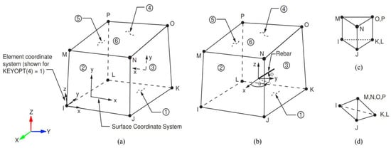
Figure 4.
(a) Solid 65 geometry was used for the concrete sections. (b) Solid 45 geometry was modeled for the solid. (c) Prism option for both elements. (d) Tetrahedral option for both elements [23].
This particular element, capable of modeling reinforcement in three dimensions, has been applied independently to various components such as roofs, slabs, columns, and walls. This usage has led to separate property definitions for reinforcement and materials corresponding to these components. The Fluid 80 element, a modification of the three-dimensional structural component known as Solid 45, is used for modeling non-fluid materials within tanks. This element is particularly useful in calculating hydrostatic pressure and fluid–structure interaction scenarios. As illustrated in Figure 4b, this element is characterized by including eight nodes, each possessing three displacement degrees of freedom. The degrees of freedom related to the interaction surface component correspond with the adjacent node degree of freedom of the tank wall, specifically in the direction perpendicular to the tank wall.
Additionally, the fluid element incorporates special surface effects, conceptualized as gravity springs that help maintain the surface’s position. This is achieved by adding springs to each node and positioning the springs with positive constants at the top of the element. The springs are connected from each node, having positive stiffness at the top nodes and negative stiffness at the bottom nodes. Consequently, they counterbalance the positive and negative impacts on an intermediate node from each other.
At the base of the fluid, which the container needs to restrain to prevent settling, the spring ceases to have an effect as it closes off the fluid nodes and the container wall. Suppose the bottom of the container is on an elastic bed or buoyancy occurs. In that case, the free surface of the liquid should be set in the coordinates z = 0 to neutralize the effect of this spring on the bottom, and only positive springs should be used on the free surface.
3.2.3. Boundary Conditions
Semi-infinite ground boundaries were employed as energy-absorbing perimeters to mimic the radiation condition. These boundaries have a distinctive feature where the waves generated from striking the structure and bouncing back to the ground are absorbed in the boundary surfaces, thereby preventing errors in determining necessary solutions. The energy absorption characteristics depend on the material properties and frequency content, as illustrated in Figure 5. Nevertheless, past studies conducted by Lymser and Kuhlmeyer [48,49,50] have shown that a finite element model incorporating viscous dampers is a credible representation of the interaction between soil and structure.
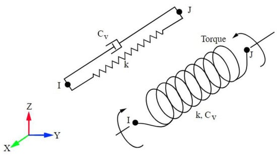
Figure 5.
Combine 14 figure (the element is defined by two nodes, I and J, a spring constant (k) and damping coefficient (Cv)) [23].
4. Results and Discussion
4.1. General Aspects
This section will conduct a sensitivity analysis and parametric study to investigate the influence of various parameters on the seismic behavior of rectangular semi-buried tanks. Understanding the sensitivity of the tank’s response to these parameters is crucial in optimizing the design and enhancing the safety of such structures. The following parameters will be considered in the study:
- Water Level: We will examine the effect of varying water levels on the tank’s seismic response. Different water levels, from empty to complete, will be analyzed to understand how the tank behaves under various loading conditions;
- Soil Properties: The seismic behavior of the tank is greatly influenced by the surrounding soil properties. We will investigate the impact of different soil types on the tank’s response, including stiffness, shear modulus, bulk modulus, and Poisson’s ratio;
- Tank Wall Thickness: The thickness of the tank wall plays a significant role in its structural integrity. We will explore how different wall thicknesses affect the tank’s seismic performance;
- Expansion Joint Type: Comparing the effects of different expansion joint types on the tank’s response will provide valuable insights into the importance of expansion joints in mitigating seismic stresses;
- Roof Presence: We will study the influence of having a roof on the tank’s behavior during seismic events. A roof’s presence or absence can affect the tank’s overall stiffness and response;
- Damping Coefficients: The damping coefficients α and β play a crucial role in dissipating energy during seismic events. We will analyze the sensitivity of the tank’s response to different damping values;
- Earthquake Ground Motion: Variations in earthquake ground motion characteristics will also be considered. Different earthquake records with varying frequency content and intensity will be used to evaluate the tank’s response under different seismic scenarios.
The sensitivity analysis and parametric study will involve running multiple dynamic simulations with different parameter combinations. The results will be compared and analyzed to identify the most influential parameters and their effect on the tank’s behavior. This information will provide valuable insights into the design and seismic performance optimization of rectangular semi-buried tanks, ensuring their safety and reliability in earthquake-prone regions.
By conducting this comprehensive sensitivity analysis and parametric study, we aim to enhance further the understanding of the seismic response of rectangular semi-buried tanks, considering fluid–structure and soil–structure interaction. The findings of this study will contribute to better design guidelines and risk assessment methodologies for liquid storage tanks, improving the overall resilience of critical infrastructure in earthquake-prone areas.
Modal Analysis/Verification of Simulation
The vibration parameters of a tank include the natural frequencies and modal shapes, which are essential parameters in its analysis. Determining these parameters in the first step can be very helpful in interpreting the behavior of the tank. In addition, modal analysis has been used to determine these characteristics. This type of analysis can also be a starting point for other studies, such as time history analysis. The first reason is to verify the model by extracting the first frequency from the modal analysis and comparing it with the values of the code. The second reason is to calculate the α and β coefficients.
For Equations (8) and (9), the convective mode period determined from the water-filled model was compared with the values from the ACI regulations to validate the model. According to the ACI [36] regulation, the following results were obtained: HL = 5 m, L = 30.63 m, and λ = 3.8352 for a convective period of 9.07 s. The software outputs gave a convective time of 9.04 s, which is almost the same, and the agreement between the theoretical and software values shows the accuracy of the modeling. In dynamic analysis, the main objective is to solve the equation of motion for the successive accelerations of the structure. The damping matrix for the overall system’s equation of motion combines the damping matrices for the viscous fluid components and the structures. For the damping of structures, Riley’s damping assumption was used. The damping is linearly dependent on mass and stiffness. In this case, Equation (10) is obtained:
where [CFi] is the damping matrix of element i, the viscous fluid, and m is the number of fluid elements [40]. Based on the damping coefficients proposed in the ACI 350 regulations, 5% of the coefficients α = 0.0228 and β = 0.0087 were determined for shock damping and 0.5% of the coefficients α = 0.0228 for vibration damping, respectively [41].
[C] = α[M] + β[K] + ∑mi = 1 [Cfi]
To facilitate comparison and establish validation, results from a laboratory-scaled model incorporating a rigid floor within a three-dimensional space have been utilized [51]. In the specified laboratory example, a scaled-down model undergoes testing on a shaking table subject to an El Centro earthquake component, with a time record scaled up by a factor of four and a peak acceleration value of 0.22 g. Such acceleration is visually represented in Figure 6.
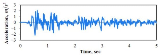
Figure 6.
Time history of the acceleration component of the El Centro earthquake [51].
The analysis covers the time history of acceleration at the middle section of the elongated wall, alongside the time history of hydrodynamic pressure at the intersection between the floor slab and the central section of the wall’s expansive face. The introduction should articulate the study’s originality, and any constraints or limitations found in previous research should be noted.
For verification, the results of the model and the reference laboratory model [51] are compared in Figure 7 and Figure 8. The maximum acceleration and hydrodynamic pressure values are 2.41 m/s2 and 1.4 KPa for the experimental model and 2.25 m/s2 and 1.31 KPa for the current model under the mentioned accelerogram. The relatively decent adaptation of the results is proof of the accuracy of the modeling.
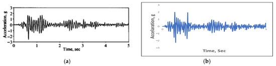
Figure 7.
The time history of the measured acceleration at the top of the middle section (a) Laboratory model; (b) model.
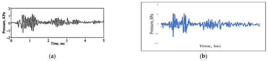
Figure 8.
Time history of hydrodynamic pressure in the interface between the floor slab and the middle section of the wall. (a) Laboratory model; (b) model.
4.2. Time History Analysis
4.2.1. General Aspects
The process of time history analysis is initiated with static analysis. The variations between the models for dynamic and static analyses lie in utilizing energy-absorbing boundaries and α- and β-coefficients to account for Riley damping and differences in material properties. In this research, dynamic time history analysis was employed. It was essential to adjust the data set to compare the results of equivalent dynamic time history analysis during scaling. The acceleration of the Tabas earthquake was selected as the reference acceleration curve. Specifically, the initial 20 s of the Tabas earthquake, which harbored the highest energy of the earthquake, were chosen for analysis. To scale the peak acceleration of the Tabas earthquake to 0.35 g, dynamic analyses were conducted with a 1.23 history of the acceleration of this earthquake. Since the studies focus on soil properties, the soil resistance parameters in the dynamic analysis in Table 5 are listed. Soil properties can affect the seismic performance of the tank.
Table 5.
Soil properties for dynamic analysis (Livaoglu, 2008): E—Young’s modulus; G—shear modulus; Ec—bulk modulus; and ʋ—Poisson’s ratio.
4.2.2. Soil Pressure on the Wall
As shown in Figure 9, as in the static analysis of all soil types, the pressure on the surface increases with increasing water level. The main reason is the reduced freedom of movement of the soil due to water pressure on the tank increasing the soil pressure on the wall at the soil surface level.
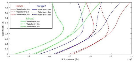
Figure 9.
Soil pressure at the tank wall according to different types of soil and water level in the tank.
4.2.3. Soil Pressure on the Tank
Figure 10 depicts that the soil pressure at the tank wall increases due to a change in soil type (increase in modulus of elasticity and ϕ, and decrease in C). The curvature at the top of the pressure shows the effect of water on different types of tanks. As the amount of water increased, the pressure at the soil surface increased. With increasing soil depth increased, this pressure increased dramatically and nonlinearly.
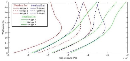
Figure 10.
Soil pressure at the tank wall for different soil types according to the water level in the tank.
4.2.4. Maximum Tensile Stress
On the Tank Wall
Figure 11 demonstrates that the tensile stress values are considerably higher in soft soil than in other soil types, given the same structure and seismic forces. In soft and normal soils (types 1 and 2), the critical condition arises in the empty tank and the thicker part of the wall. This is attributed to maximum tensile stress in the empty tank wall at a height ranging between 0 and 1 m from the foundation, which can be traced back to the thicker wall footing that enhances stiffness. Consequently, heightened stiffness augments the tanks’ capacity to bear greater loads.
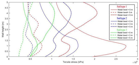
Figure 11.
Maximum tensile stress at the tank wall according to the different types of soil and the water level in the tank.
The peak tensile stress is observed when the soil is hard in the water-filled tank. However, the maximum values are approximately one-third of those in soft soil. The rationale behind the high tensile stresses above the wall in all analyses is incorporating the floor in the model. In a general sense, the presence of the slab restricts the wall from functioning as a complete cantilever.
In addition, the change in soil material from sand to clay significantly increased the tensile stress in the tank wall. The main reason for this behavior was the hardening of the tank wall relative to the soil, making the tank wall capable of withstanding more stress.
4.2.5. On the Expansion Joint
Upon contrasting the respective results from the tank wall and the expansion joints, it becomes apparent that the tensile stress within the expansion joints surpasses that within the wall. A comparison highlighting the peak tensile stress in the adjacent wall and the wall expansion joints for soil type 1 is presented in Figure 12. This value escalates when the tank is water-filled, with the peak point value reaching 23% and decreasing with a reduction in the water volume within the tank.
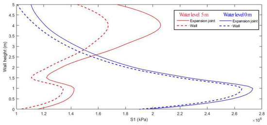
Figure 12.
Maximum tensile stress in wall and expansion joint (soil type 1) based on the water level in the tank.
As previously noted, the maximum tensile stress for the concrete considered in this study was 2.71 MPa. When comparing the maximum tensile stress in the wall and the adjoining wall expansion joints, it is observed that the expansion joints are fully engaged and reach up to 2.73 MPa. This result suggests a potential for cracking in the tank. Furthermore, leaks from the tank fluid may cause minor damage, potentially leading to irreversible harm.
4.2.6. Displacement
On the Tank
A comparison of maximum displacement in half-buried concrete tanks shows the influence of liquid on seismic response. Thus, in soft (Figure 13) and complex (Figure 14) soils, tanks without water displace about 10% compared to tanks filled with water. The previous observation demonstrates that the seismic response of the tank is impacted by both impulsive and convective components, which are responsible for the fluid’s motion. Henceforth, it is imperative to consider the interplay of factors in liquid tanks during the dynamic assessment of such structures.
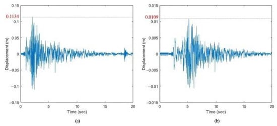
Figure 13.
Comparison of displacements between (a) filled and (b) empty tanks in soil type 1.
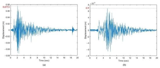
Figure 14.
Comparison of displacements between (a) filled and (b) empty tanks in soil type 3.
On the Tank with and without the Roof
Liquid tanks may or may not have a roof, but as mentioned earlier, potable water tanks must always have one. Figure 15 shows the effect of the presence or absence of a roof on the displacement of points at the highest points of the tank wall. For the reasons given, the most significant displacement occurs in water-filled tanks and soft soil. The presence of a concrete roof reduces the maximum displacement at the top of the wall in a filled tank in soil type 1 by almost 15% as a critical value.
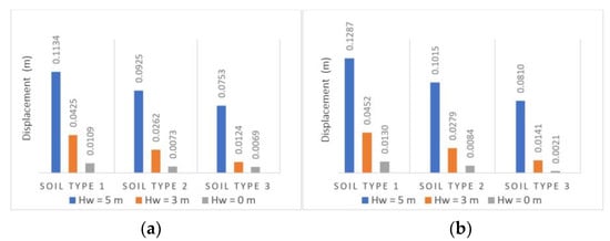
Figure 15.
Comparison of maximum displacement depending on soil and water in a tank (a) with and (b) without the roof.
5. Qualitative Assessment
Methods of qualitative assessment, which include objective evaluations, expert reviews, statistical approaches, or fragility curves, can serve useful functions. These methods are particularly significant in studies requiring structural improvements, where they are based on site visits and observations of various structural components and features. Due to their simplicity and practicality, these methods can assist designers in prioritizing structures for more detailed quantitative analyses. Concurrently, they provide cost and time efficiency to projects by identifying elements that do not require repair or rehabilitation.
The Japan International Cooperation Agency (JICA) reviewed the risk and damage assessment of Tehran’s water supply system [6] and, in this context, conducted general and comprehensive surveys of all components of the water supply system, including drinking water tanks. It should be noted that the Japanese Vibration Capacity Detection Table (DTSC) is dedicated to studies related to the qualitative evaluation of point components of water systems such as reservoirs (open and roof). The Japanese Vibration Capacity Detection Table (DTSC) method is the most practical measurement method for damage assessment. This method evaluates fourteen risk factors in terms of fragility. First of all, the above parameters should be considered in the objective inspections of the water supply system component, and a qualitative status should be assigned to them. In the next step, the qualitative status of each damage parameter is quantified using the corresponding tables for the tanks and assigned to each number representing the damage index of this assumed parameter.
Based on Table 6, the risk level is calculated according to Equation (11):
Risk Level = Damage Index Parameter No. 1 × … × Damage Index Parameter No. 14
Table 6.
Risk level [6].
The total damage index is obtained by multiplying all damage indices related to the 14 introduced parameters. The overall damage index indicates the estimated vulnerability status of a particular system component, which is in the range of high, medium, and low seismic resilience, depending on the number achieved. Damage ratings for the fourteen risk factors are performed using the DTSC table (Table 7).
Table 7.
Damage indexes of DTSC method parameters for tanks [6] and calculated risk level for four samples (a tank without water in hard soil (Sample No. 1), a tank full of water in hard soil (Sample No. 2), a tank without water in soft soil (Sample No. 3) and a tank full of water in soft soil (Sample No. 4).
Based on the quantitative evaluation conducted in this study, four examples of liquid storage tanks, namely, an empty tank of water in hard soil (Sample No. 1), a tank filled with water in hard soil (Sample No. 2), an empty tank of water in soft soil (Sample No. 3), and a tank filled with water in soft soil (Sample No. 4) were evaluated according to Table 7. It should be noted that the parameters not included in the model, such as the year of construction, etc., are used with a coefficient of 1. Based on the qualitative evaluation, the maximum risk level is for a tank full of water in soft soil or empty in soft soil. The results show the importance of soil type in the storage tank filling ratio in the qualitative assessment.
6. Conclusions
This study provides valuable insights into the seismic behavior of liquid storage tanks. It highlights the importance of considering soil properties, water level, and roof type in tank design and risk assessment. These findings will be beneficial for improving the seismic design guidelines and enhancing the safety and stability of critical infrastructures in earthquake-prone regions. The qualitative evaluation methodology can also be applied to prioritize tanks for quantitative studies, optimizing resources and decision-making processes in structural improvement projects. Overall, this research contributes to advancing the understanding and resilience of liquid storage tanks under seismic conditions. The study’s findings can be briefly summarized as follows.
The soil type greatly affected the maximum tensile stress on the tank walls. Tanks in soft soil experienced three times the maximum tensile stress compared to hard soil, regardless of the water content. A concrete roof significantly reduced the displacement at the tank walls, emphasizing the importance of roof type in seismic resilience.
The presence of a concrete roof demonstrated a positive impact on the tanks’ seismic resilience. Roofed tanks experienced reduced displacement at the top of the wall compared to uncovered tanks. The type of connection between the tank roof and the wall significantly affected the results. In particular, the cantilevered roof was responsible for the high tensile stresses observed above the wall, especially when the tank was filled with water. As the water content increases, the effect of the lateral forces on the tank wall shifts upward. The presence of a concrete roof reduces the maximum displacement at the location of the wall by almost 10 to 15%.
The displacement results illustrate the effect of the FSI on the seismic response. In hard and soft soils, empty tanks have a displacement of about 10% compared to tanks filled with water. The present study demonstrates the influence of the impulsive and convective fluid motion components on the seismic response of the tank.
Furthermore, the study applied qualitative assessment methods to evaluate the vulnerability of the tanks. The qualitative evaluation highlighted the critical role of soil type and water content in determining the risk level of the tank. The results revealed that tanks empty in soft soil pose the highest risk in terms of seismic resilience. This research provided valuable risk assessment data for different tank configurations and soil types. The results indicated that tanks filled with water in soft soil or empty in soft soil posed the highest risk in terms of seismic resilience. Understanding such risk levels can aid in decision-making regarding the reinforcement and retrofitting of vulnerable tanks.
Author Contributions
Conceptualization, B.P.; methodology, B.P. and A.M.B.; software, B.P. and E.B.; validation, B.P., A.M.B. and E.B.; formal analysis, S.N.D., S.F. and J.C.M.; investigation, B.P.; writing—original draft preparation, B.P. and A.M.B.; writing—review and editing, S.N.D. and J.C.M.; supervision, A.M.B., S.N.D. and J.C.M.; funding acquisition, S.N.D., S.F. and J.C.M. All authors have read and agreed to the published version of the manuscript.
Funding
This research received no external funding.
Institutional Review Board Statement
Not applicable.
Informed Consent Statement
Not applicable.
Data Availability Statement
Not applicable.
Acknowledgments
The presented work was performed in context of the Horizon Europe project SARIL which is funded by the European Union under grant agreement ID 101103978. Views and opinions expressed are however those of the author(s) only and do not necessarily reflect those of the European Union or the European Climate, Infrastructure and Environment Executive Agency. Neither the European Union nor the granting authority can be held responsible for them.
Conflicts of Interest
The authors declare no conflict of interest.
References
- Taufiq Rochman, S. State of the art of tank structural evaluation review: A case study of an elevated concrete water tank concerning crack initiation. J. Southwest Jiaotong Univ. 2021, 56, 90–106. [Google Scholar] [CrossRef]
- Tehran Province Water & Wastewater Organization’s Information Center. 2015. Available online: https://www.tpww.ir/ (accessed on 5 April 2023).
- US EPA. Available online: https://www.epa.gov/ust/underground-storage-tanks-usts-laws-and-regulations (accessed on 5 April 2023).
- Housner, G.W. Dynamic pressures on accelerated fluid containers. Bull. Seism. Soc. Am. 1957, 47, 15–35. [Google Scholar] [CrossRef]
- Fischer, D. Dynamic fluid effects in liquid-filled flexible cylindrical tanks. Earthq. Eng. Struct. Dyn. 1979, 7, 587–601. [Google Scholar] [CrossRef]
- JICA. Available online: https://openjicareport.jica.go.jp/618/618/618_304_11841657.html (accessed on 5 April 2023).
- New Zealand Society for Earthquake Engineering. New Zealand Society for Earthquake Engineering; Seismic Design of Storage Tanks: Christchurch, New Zealand, 2009. [Google Scholar]
- Haroun, M.A. Vibration studies and tests of liquid storage tanks. Earthq. Eng. Struct. Dyn. 1983, 11, 179–206. [Google Scholar] [CrossRef]
- Veletsos, A.S.; Tang, Y. Soil-structure interaction effects for laterally excited liquid storage tanks. Earthq. Eng. Struct. Dyn. 1990, 19, 473–496. [Google Scholar] [CrossRef]
- Hanna, Y.G.; Humar, J.L. Boundary Element Analysis of Fluid Domain. J. Eng. Mech. Div. 1982, 108, 436–450. [Google Scholar] [CrossRef]
- Malhotra, P.K.; Wenk, T.; Wieland, M. Simple procedure for seismic analysis of liquid-storage tanks. Structural Engineering International. J. Int. Assoc. Bridge Struct. Eng. 2000, 10, 197–201. [Google Scholar] [CrossRef]
- Ruiz, R.; Lopez-Garcia, D.; Taflanidis, A. An efficient computational procedure for the dynamic analysis of liquid storage tanks. Eng. Struct. 2015, 85, 206–218. [Google Scholar] [CrossRef]
- Kangda, M.Z. An approach to finite element modeling of liquid storage tanks in ANSYS: A review. Innov. Infrastruct. Solut. 2021, 6, 226. [Google Scholar] [CrossRef]
- Pal, N.C.; Sinha, P.K.; Bhattacharyya, S.K. Finite Element Coupled Slosh Analysis of Rectangular Liquid Filled Laminated Composite Tanks. J. Reinf. Plast. Compos. 1999, 18, 1375–1407. [Google Scholar] [CrossRef]
- Krishnamoorthy, A. Finite Element Method of Analysis for Liquid Storage Tank Isolated with Friction Pendulum System. J. Earthq. Eng. 2021, 25, 82–92. [Google Scholar] [CrossRef]
- Wu, G.; Luo, J.; Li, L.; Long, Y.; Zhang, S.; Wang, Y.; Zhang, Y.; Xie, S. Control of Welding Residual Stress in Large Storage Tank by Finite Element Method. Metals 2022, 12, 1502. [Google Scholar] [CrossRef]
- Altan, M.F.; Alçan, H. Foundation Design Analysis with Finite Element Method in the Reinforcement of Liquid Storage Tanks. EURAS J. Eng. Appl. Sci. 2021, 2, 69–78. [Google Scholar] [CrossRef]
- Baghban, M.H.; Tosee, S.V.R.; Valerievich, K.A.; Najafi, L.; Faridmehr, I. Seismic Analysis of Baffle-Reinforced Elevated Storage Tank Using Finite Element Method. Buildings 2022, 12, 549. [Google Scholar] [CrossRef]
- Rebouillat, S.; Liksonov, D. Fluid–structure interaction in partially filled liquid containers: A comparative review of numerical approaches. Comput. Fluids 2010, 39, 739–746. [Google Scholar] [CrossRef]
- Haroun, M.A. Dynamic Analyses of Liquid Storage Tanks; California Institute of Technology, Earthquake Engineering Research Laboratory (Report) EERL: Pasadena, CA, USA, 1980; pp. 80–84. [Google Scholar]
- Livaoglu, R. Investigation of seismic behavior of fluid–rectangular tank–soil/foundation systems in frequency domain. Soil Dyn. Earthq. Eng. 2008, 28, 132–146. [Google Scholar] [CrossRef]
- Haroun, M.A. Stress analysis of rectangular walls under seismically induced hydrodynamic loads. Bull. Seism. Soc. Am. 1984, 74, 1031–1041. [Google Scholar] [CrossRef]
- SAS IP, Inc. Available online: https://pdfcoffee.com/ansys-theory-reference-4-pdf-free.html (accessed on 5 April 2023).
- Park, J.-H.; Koh, H.M.; Kim, J. Fluid-Structure Interaction Analysis by a Coupled Boundary Element-Finite Element Method in Time Domain; Springer: Berlin/Heidelberg, Germany, 1992; pp. 227–243. [Google Scholar] [CrossRef]
- Kim, J.K.; Koh, H.M.; Kwahk, I.J. Dynamic Response of Rectangular Flexible Fluid Containers. J. Eng. Mech. 1996, 122, 807–817. [Google Scholar] [CrossRef]
- Kianoush, M.; Chen, J. Effect of vertical acceleration on response of concrete rectangular liquid storage tanks. Eng. Struct. 2006, 28, 704–715. [Google Scholar] [CrossRef]
- Chen, J.Z.; Kianoush, M.R. Seismic response of concrete rectangular tanks for liquid containing structures. Can. J. Civ. Eng. 2005, 32, 739–752. [Google Scholar] [CrossRef]
- Nicolici, S.; Bilegan, R. Fluid structure interaction modeling of liquid sloshing phenomena in flexible tanks. Nucl. Eng. Des. 2013, 258, 51–56. [Google Scholar] [CrossRef]
- Jamalabadi, M.Y.A. An Improvement of Port-Hamiltonian Model of Fluid Sloshing Coupled by Structure Motion. Water 2018, 10, 1721. [Google Scholar] [CrossRef]
- Tang, Y.; Veletsos, A.S. Soil-Structure Interaction Effects for the Laterally Excited liquid-Tank System; No. ANL/CP-75432; CONF-920631-24; Argonne National Lab.: Lemont, IL, USA, 1992. [Google Scholar]
- Livaoǧlu, R.; Doǧangün, A. Simplified seismic analysis procedures for elevated tanks considering fluid-structure-soil interaction. J. Fluids Struct. 2006, 22, 421–439. [Google Scholar] [CrossRef]
- Tsipianitis, A.; Tsompanakis, Y.; Psarropoulos, P.N. Impact of Dynamic Soil–Structure Interaction on the Response of Liquid-Storage Tanks. Front. Built Environ. 2020, 6, 140. [Google Scholar] [CrossRef]
- Satyanaga, A.; Rahardjo, H.; Koh, Z.H.; Mohamed, H. Measurement of a soil-water characteristic curve and unsaturated permeability using the evaporation method and the chilled-mirror method. J. Zhejiang Univ. A 2019, 20, 368–374. [Google Scholar] [CrossRef]
- Zhai, Q.; Rahardjo, H.; Satyanaga, A. Uncertainty in the estimation of hysteresis of soil–water characteristic curve. Environ. Geotech. 2019, 6, 204–213. [Google Scholar] [CrossRef]
- Zhai, Q.; Rahardjo, H.; Satyanaga, A.; Dai, G. Estimation of tensile strength of sandy soil from soil–water characteristic curve. Acta Geotech. 2020, 15, 3371–3381. [Google Scholar] [CrossRef]
- Satyanaga, A.; Wijaya, M.; Zhai, Q.; Moon, S.-W.; Pu, J.; Kim, J.R. Stability and Consolidation of Sediment Tailings Incorporating Unsaturated Soil Mechanics. Fluids 2021, 6, 423. [Google Scholar] [CrossRef]
- Zhai, Q.; Rahardjo, H.; Satyanaga, A.; Dai, G.-L.; Du, Y.-J. Effect of the uncertainty in soil-water characteristic curve on the estimated shear strength of unsaturated soil. J. Zhejiang Univ. A 2020, 21, 317–330. [Google Scholar] [CrossRef]
- Frandsen, J. Numerical predictions of tuned liquid tank structural systems. J. Fluids Struct. 2005, 20, 309–329. [Google Scholar] [CrossRef]
- Tra, V.; Duong, B.-P.; Kim, J.-Y.; Sohaib, M.; Kim, J.-M. Improving the Performance of Storage Tank Fault Diagnosis by Removing Unwanted Components and Utilizing Wavelet-Based Features. Entropy 2019, 21, 145. [Google Scholar] [CrossRef] [PubMed]
- IBC. IBC 2000, International Building Code; International Code Council: Falls Church, VA, USA, 2000. [Google Scholar]
- ACI 350.3. Available online: https://www.concrete.org/Portals/0/Files/PDF/Previews/350.3-20_preview.pdf (accessed on 5 April 2023).
- Jaiswal, O.R.; Rai, D.C.; Jain, S.K. Review of Seismic Codes on Liquid-Containing Tanks. Earthq. Spectra 2007, 23, 239–260. [Google Scholar] [CrossRef]
- Hussein, A.A.; Al-Neami, M.A.; Rahil, F.H. Hydrodynamic Pressure Effect of the Tank Wall on Soil–Structure Interaction. In Modern Applications of Geotechnical Engineering and Construction; Springer: Singapore, 2021; pp. 173–184. [Google Scholar] [CrossRef]
- Kotrasová, K. Study of Hydrodynamic Pressure on Wall of Tank. Procedia Eng. 2017, 190, 2–6. [Google Scholar] [CrossRef]
- Khati, T.; Kaloni, S.; Narayan, S. Computational fluid dynamics analysis of elevated circular water tank. J. Graph. Era Univ. 2020, 8. [Google Scholar]
- Chandra, T.; Setia, S. Seismic Assessment of RC Framed Staging of Elevated Water Tanks. In Recent Advances in Earthquake Engineering; Springer: Singapore, 2022; pp. 69–76. [Google Scholar] [CrossRef]
- Standard No. 123; Design and Analysis of Ground Concrete Water Reservoirs (a Revision on Standard No. 123), Office of Deputy for Technical and Infrastructure Development Affairs Department of Technical Affairs. Bureau of Technical, Engineering, Social and Environmental Standards of Water and Waste Water: London, UK, 2015.
- Kuhlemeyer, R.L.; Lysmer, J. Finite Element Method Accuracy for Wave Propagation Problems. J. Soil Mech. Found. Div. 1973, 99, 421–427. [Google Scholar] [CrossRef]
- Lysmer, J.; Kuhlemeyer, R.L. Finite Dynamic Model for Infinite Media. J. Eng. Mech. Div. 1969, 95, 509–511. [Google Scholar] [CrossRef]
- Derrick, N.; Srivastava, A.K. Effect of Mesh Size on Soil-Structure Interaction in Finite Element Analysis. Int. J. Eng. Res. Technol. 2020, 9, 802–807. [Google Scholar]
- Koh, H.M.; Kim, J.K.; Park, J.-H. Fluid-structure interaction analysis of 3-D rectangular tanks by a variationally coupled BEM-FEM and comparison with test results. Earthq. Eng. Struct. Dyn. 1998, 27, 109–124. [Google Scholar] [CrossRef]


Disclaimer/Publisher’s Note: The statements, opinions and data contained in all publications are solely those of the individual author(s) and contributor(s) and not of MDPI and/or the editor(s). MDPI and/or the editor(s) disclaim responsibility for any injury to people or property resulting from any ideas, methods, instructions or products referred to in the content. |
© 2023 by the authors. Licensee MDPI, Basel, Switzerland. This article is an open access article distributed under the terms and conditions of the Creative Commons Attribution (CC BY) license (https://creativecommons.org/licenses/by/4.0/).