Abstract
To investigate the toughening effect and stress–strain relationship of steel fibre-reinforced steel slag micropowder ultra-high-performance concrete (UHPC), nine sets of specimens with coarse aggregate and steel fibre contents were prepared for axial compression and elastic modulus tests. This study examines the variations in compressive strength and peak strain of the steel slag micropowder UHPC specimens to determine the corresponding characteristics of the stress–strain relationship. The results indicate that the experimental groups mixed with 1%, 1.5%, and 2% steel fibre increased the peak strain by about 20.3%, 25.3%, and 26.2%, respectively, compared to the non-steel fibre specimens. It can be seen that the toughening effect of UHPC with steel fibre and slag micro powder is good. With a fixed steel fibre content, the compressive strength and peak strain of steel slag micropowder UHPC initially increase and then decrease as the coarse aggregate content increases. The maximum compressive strength is achieved when the steel fibre content is 1.5% and the coarse aggregate content is 20%. A constitutive equation suitable for steel fibre-reinforced steel slag micropowder UHPC was derived through curve fitting based on the experimentally obtained stress–strain curves. The calculated values from the equation show deviations within 10% of the measured values, indicating a good fit. Nonlinear analysis of the entire compression process of prismatic specimens using the finite element method confirms the rationality of the constitutive equation, as the simulated curve closely aligns with the experimental curve. This research findings provide a reference for the engineering application of steel slag micropowder UHPC.
1. Introduction
Ultra-high-performance concrete (UHPC) is a novel concrete type prepared based on the optimal compactness principle. It demonstrates exceptional mechanical properties and durability, including high strength and toughness, making it a highly promising material for implementation in bridge engineering. In recent years, numerous studies have been conducted in the field of bridge engineering to investigate the fundamental research of UHPC. However, due to its high production cost, its practical application in engineering remains relatively limited [1,2,3,4]. To reduce preparation costs, some researchers have replaced quartz powder in UHPC with processed steel slag micropowder, resulting in cost-effective, environmentally friendly steel slag micropowder UHPC with high mechanical strength and durability [5,6,7].
Although high-strength and durable steel slag micro powder UHPC can meet the mechanical performance requirements in practical applications, this type of concrete also has disadvantages, such as a low water–cement ratio and easy cracking in the early stage. How to improve the strength of concrete materials while ensuring their toughness and reducing brittleness has become the key to the development of concrete [8]. Adding fibre to UHPC can reduce the brittleness of UHPC materials, control cracking, and improve ductility [9]. Among fibre materials, steel fibres have the characteristics of high elastic modulus and high tensile strength, which have a particularly significant improvement effect on the toughness of concrete [10]. Therefore, a certain amount of steel fibre can be added to steel slag micro powder UHPC to improve its compressive strength and toughness and reduce the problems of early cracking and high brittleness of steel slag micro powder UHPC. At the same time, research has found that adding a certain volume of coarse aggregate to UHPC can further reduce the preparation cost without affecting its performance [11,12] and can also improve the elastic modulus and compressive strength of concrete to a certain extent. Therefore, it can be attempted to add a certain amount of coarse aggregate to steel slag micro powder UHPC to optimize its performance while reducing costs again.
The stress–strain relationship reflects the fundamental mechanical properties of UHPC, and the study and analysis of its stress–strain curve equation are of significant importance. Many scholars have conducted relevant research in this area. Luo Min [13] investigated the different fibre contents on the uniaxial compressive mechanical properties of UHPC specimens and derived the constitutive relationship for UHPC with various fibre additions. Ma Lingling [14] established a constitutive model for restrained ultra-high-performance concrete based on theoretical analysis and regression analysis. This constitutive model, validated through plastic damage analysis and comparison with load–displacement curves, is suitable for finite element analysis. Zeng Zhiwei [15] studied the uniaxial behaviour of confined coarse aggregate ultra-high-performance concrete (CA-UHPC) under compression deformation and theoretically derived the constitutive model for CA-UHPC. EL-HELOU R G [16] considered the multiaxial stress–strain behaviour of the cementitious matrix and the stress–slip response of fibres, proposing a triaxial constitutive model for fibre-reinforced cementitious material UHPC. Guo Xiaoyu et al. [17] individually analysed the uniaxial constitutive equations proposed in different literature for UHPC and demonstrated that using the constitutive equation proposed in the “Code for Design of Concrete Structures” yields higher accuracy in calculating the uniaxial stress–strain relationship of UHPC. WILLIAMS E M [18] investigated the constitutive performance behaviour of ultra-high-performance composite concrete by conducting mechanical performance tests on specimens prepared with and without steel fibres. In summary, although extensive studies have been conducted on the constitutive relationship of conventional UHPC both domestically and internationally, research on the constitutive relationship of steel slag micropowder UHPC remains scarce.
In this study, to establish the constitutive relationship of steel slag micropowder UHPC and analyse its mechanical properties, experiments were conducted by incorporating steel fibres with different volume ratios and varying amounts of coarse aggregate. The objective was to explore its failure characteristics and stress–strain relationship. Through derivation and curve fitting, the stress–strain equation for steel slag micropowder UHPC was obtained, providing technical support for its application in bridge engineering.
2. Experimental Section
2.1. Raw Materials
The raw materials used in the experiments included the following: Ordinary Portland cement (OPC) of Hai Luo brand with a grade of 42.5. Silica fume produced in Nanning, with a specific surface area of 2200 m2/kg and a density of 1.52 g/cm3. Steel slag micropowder obtained by grinding steel slag and 18% grade II fly ash. Polycarboxylate superplasticizer solution with a water-reducing rate greater than 30%. Mechanism river sand with a fineness modulus of 2.47. Steel fibres with a length of 15 mm, flat type, a diameter of 0.22 mm, and a tensile strength of 2500 MPa. Coarse aggregate consisting of crushed stone with particle sizes ranging from 5 to 20 mm and a parent rock strength of 120 MPa. The main chemical composition of the cementitious materials is presented in Table 1, and the gradation of various materials is shown in Figure 1. Figure 2 shows the Scanning electron microscope (SEM) image of the cementitious materials.

Table 1.
Main chemical components of cementitious materials.
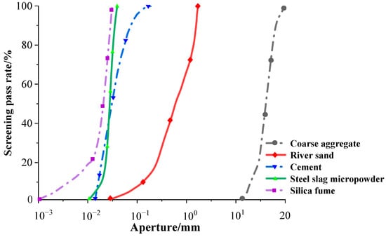
Figure 1.
Sieving curves of raw materials.
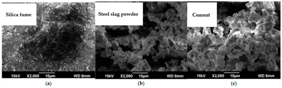
Figure 2.
SEM image of cementitious materials.
The SEM image of the cementitious materials is shown in Figure 2. Figure 2a–c show silica fume, steel slag powder, and cement, respectively. It can be observed that the silica fume has a smaller particle size and more uniform particles. The steel slag micropowder exhibits relatively loose accumulation. The cement particles are also uniform and compacted well.
2.2. Basic Mix Proportion Design
This experiment is based on the tightest packing theory for basic mix proportion design. Due to the advantage of considering particle size distribution in the modified Andreasen and Andersen model (MAAM) among many UHPC mix design models based on the tightest packing theory, which is more accurate and effective [19,20], this method is used to calculate and analyse the basic mix proportion of steel slag micro powder UHPC. The calculation formula is shown in Equation (1).
where is the cumulative percentage of sieve residue with particle size less than , %; is the particle size, ; , are maximum and minimum particle size in the distribution system, respectively,; and q is the modulus of particle size distribution, taken as 0.24 in this study.
Using Python software to model and analyse Equation (1), based on the particle distribution curves and MAAM target curves of different raw materials in Figure 1, the least squares method was used to calculate the raw material ratio. By adjusting the proportion of each material to make the stacking curve as close as possible to the target curve, the basic proportion of steel slag micro powder UHPC was calculated as shown in Table 2, p10, and the fixed water–cement ratio was 0.18.
Table 2.
Mix proportions.
Steel slag micro powder is an ultrafine powder processed from steel slag through magnetic separation and ball milling technology. It contains various oxides and minerals and can form stable and high-strength granular materials. It also has a particle size and specific surface area similar to quartz powder. Using the above mix ratio to replace some quartz powder with steel slag micro powder can reduce the production cost of UHPC to a certain extent and achieve waste utilization, effectively solving the resource utilization problem of solid waste from steel manufacturers. UHPC can be mixed with coarse aggregate without affecting its performance, which can further reduce the cost. In view of the greater brittleness of UHPC and the improvement in its toughness by adding a certain amount of steel fibre, the following tests prove that a reasonable amount of steel slag micro powder Ecotype UHPC can be prepared.
2.3. Experimental Design
To investigate the effects of steel fibre content and crushed stone content, nine sets of specimens were prepared; a certain amount of coarse aggregate and steel fibre was added on the basis of the P10 basic mix proportion, with each factor at three levels. Each group of specimens included twelve 100 × 100 × 100 mm cubes for compression, splitting tensile tests, and six 100 × 100 × 300 mm prisms were used for axial compression tests and elastic modulus tests. Additionally, a control group without added steel fibres was included. The water-to-binder ratio (w/b) for all specimens was 0.2, and the sand-to-binder ratio (s/b) was 0.7. Considering that the addition of steel fibre and coarse aggregate can affect the construction performance and air content of concrete, which directly affect the compressive strength of concrete, a certain amount of polycarboxylic acid water-reducing agent and defoamer was added to increase the workability of concrete and reduce the fluidity gap between each group of concrete. Defoamer was used to remove the increased air content caused by the addition of steel fibre aggregate. The detailed mix proportions are shown in Table 2, where SSP represents steel slag micropowder ultra-high-performance concrete.
2.4. Sample Preparation
- (1)
- Production process
In order to ensure that each component material can be evenly mixed and thoroughly mixed, this experiment refers to the “Standard for Testing Ultra High Performance Concrete” (T/CECS 864-2021) [21] issued by the China Engineering Construction Standardization Association. Based on the actual situation of the experiment, a new preparation method is adopted, and the specific operation steps are as follows:
- ➀
- Calculate the materials of each component based on the mix ratio and weigh them for future use.
- ➁
- Pour the weighed cement, silica fume, steel slag micro powder, and river sand into the concrete mixer and pre-mix for 3 min to fully mix the dry material, obtaining the steel slag micro powder UHPC pre-mixed material.
- ➂
- Pour the weighed water and water-reducing agent into a water basin for stirring so that the water-reducing agent is evenly mixed with the water. Then, slowly add it to the steel slag micro powder UHPC pre-mix that is being stirred, and continue stirring for 8 min.
- ➃
- Use tweezers to disperse and evenly add steel fibres into the mixer, continue stirring for 3 min, and complete the preparation of steel slag micro powder UHPC mixture.
Place the prepared UHPC mixture into a steel mould that has been evenly coated with a release agent, and then place the steel mould on a vibration table for 10 to 15 s to eliminate bubbles in the slurry. After the vibration is completed, smooth the surface and immediately cover it with a layer of cling film to keep the slurry moist.
- (2)
- Curing of specimens
Firstly, place the steel mould covered with cling film in an indoor environment with a temperature of (20 ± 5) °C and a relative humidity of >50% for 1 day. Then, remove the mould and number it. After completion, immediately place the test piece in a steam curing box for high-temperature curing at (90 ± 5) °C for 2 days. Then, place it in a standard curing box for standard curing at (20 ± 5) °C and a relative humidity of >90%. When the testing period is reached (3th day, 7th day, and 28th day), take it out for testing.
2.5. Experimental Methods
The experiments were conducted using a hydraulic universal testing machine. Longitudinal strain gauges were attached to the middle of the specimen’s two side faces to measure the axial strain of the steel fibre-reinforced steel slag micropowder UHPC. The strain data were collected using the UT7121Y static strain gauge. Displacement transducers were installed at the loading plate of the hydraulic press to measure the displacement of the specimen. The loading scheme employed was a stress-controlled method with a loading rate of 10 kN/s [22].
3. Experimental Results and Analysis
3.1. Mechanical Performance Results
Performance tests on the slump and expansion of steel slag micro powder UHPC and recording the data in units of mm with an accuracy of 1 mm were simultaneously conducted. The statistical results are accurate to 5 mm. Cube specimens measuring 100 mm × 100 mm × 100 mm were prepared for compressive and splitting strength tests, while prism specimens measuring 100 mm × 100 mm × 300 mm were used for axial compression and elastic modulus measurements. The specific results are shown in Table 3.
Table 3.
Compressive strength of cube and prism specimens.
The analysis of Table 3 reveals that the average compressive strength of the cube specimens for different mix proportions of steel slag micropowder UHPC reaches 105.7 MPa at 3 days, 117.4 MPa at 7 days, and 128.4 MPa at 28 days. It can be observed that the compressive strength of the steel slag micropowder UHPC cubes develops at an early stage, with the average compressive strength at 3 days reaching 82% of the 28-day value. The average compressive strength at 7 days reaches 91% of the 28-day value. The average splitting tensile strength of the steel slag micropowder UHPC is 10.3 MPa, and the average elastic modulus is 46.6 GPa. The average axial compression strength of the prism specimens is 103.3 MPa. Among the experimental groups, Group SSP2 exhibits the highest elastic modulus and the highest compressive strength for both cube and prism specimens. The axial compression strength of the steel slag micropowder UHPC prism specimens is consistently above 95.1 MPa, with an average of 105.1 MPa. The ratio of prism axial compression strength to cube compressive strength ranges from 0.80 to 0.85, which is higher compared to that of ordinary high-strength concrete (with a ratio of 0.77 to 0.82) [23]. Under vertical loading, the increased elastic modulus of the steel slag micropowder UHPC prism specimens reduces lateral deformation, narrows the range of constraint effects from the loading plate, and leads to a compressive failure mode similar to that of the cube specimens. Therefore, the ratio is higher, which is consistent with the findings [24].
3.2. Failure Process and Morphology
The failure morphology of a representative specimen from each group, along with a specimen without steel fibres for comparison, is shown in Figure 2. In Figure 2, it can be observed that the compressive failure process of the steel fibre-reinforced prism specimens in each group is generally similar. However, noticeable differences in brittle failure characteristics can be observed due to the varying content of coarse aggregate and steel fibres in the different experimental groups. The compressive failure process of the specimens can be divided into the following three stages:
- (1)
- Elastic Stage: Prior to reaching the ultimate load of 40% to 70%, the stress–strain relationship of the specimen follows a proportional growth pattern. In this stage, the compression-induced deformation of the specimen initiates slowly, and microcracks start to form and propagate within the specimen. The load and displacement exhibit a roughly linear relationship, with the curve’s slope remaining relatively constant.
- (2)
- Elastic–Plastic Stage: When the load exceeds 70% of the ultimate load, the slope of the load–displacement curve decreases. Fracturing occurs at the prism’s corners, accompanied by some surface spalling in the edge region. However, due to the micro-reinforcement effect of the steel fibres, the spalled surface maintains some cohesion with the specimen, preventing complete separation. With continued loading, surface microcracks develop and propagate towards the top and bottom of the specimen. Internal microcracks propagate outward, connecting with the surface cracks and intensifying their extension, resulting in the appearance of new cracks. As the load increases, more significant fragmentation occurs, and the cracks rapidly extend and penetrate through the specimen until reaching the peak load.
- (3)
- Failure Stage: After reaching the peak stress, accompanied by a distinct noise, the specimen undergoes splitting failure. Diagonal cracks emerge on the prism’s side surface, intersecting one or multiple concrete specimens. However, due to the reinforcing effect of the steel fibres, even in the event of specimen failure, a certain degree of integrity is maintained. This stands in stark contrast to the failure state of specimen P10 without steel fibres, highlighting the beneficial toughening effect of the steel fibres.
The 10 figures in Figure 3 show the failure morphology of the numbered specimen. By analysing Figure 3, evident ductile failure characteristics can be observed in the steel fibre-reinforced steel slag micronized UHPC specimens. The surface of the specimens shows numerous intersecting wide and deep cracks. However, the micro-reinforcement effect of the steel fibres on the cracks, combined with the anchoring effect created by the steel fibres between the coarse aggregate and the matrix, contributes to the overall improved performance of the concrete system. Despite specimen failure, the concrete structure remains relatively intact, with only some surface debris spalling. As the volume fraction of steel fibres increases, the width of cracks on the specimen surface also increases. The wide cross-section of the cracks reveals a significant presence of steel fibres exhibiting bending deformation. This is attributed to the strengthening bridging effect of the steel fibres on both sides of the developing microcracks in the specimen. The increased content of steel fibres effectively impedes the initiation and propagation of primary cracks in the specimen. Consequently, as the volume fraction of steel fibres rises, the width of cracks during specimen failure widens, indicating an enhanced toughening effect.
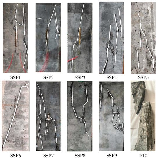
Figure 3.
Steel slag micronized UHPC prismatic experimental group.
Furthermore, by combining the information from Table 2 and Figure 3, it can be inferred that the content of coarse aggregate embedded in the UHPC specimens also influences crack development. As the content of coarse aggregate in the specimens increases, the quantity of macroscopic cracks decreases, and the specimens demonstrate radial expansion failure with severe and uneven deformation. This is attributed to the impact of increased coarse aggregate on the distribution of steel fibres within the specimen. The higher agglomeration of steel fibres caused by the increased coarse aggregate disrupts the even distribution of stress, resulting in internal cracks predominantly forming along the weakest points subjected to stress.
3.3. Analysis of Compressive Peak Strain in Prismatic Specimens
A stress–strain curve test was conducted on prismatic specimens of UHPC mixed with varying amounts of steel fibre and steel slag micro-powder. Compressive strength and peak strain values were measured for each group of UHPC specimens containing steel fibre and steel slag micro-powder. The numerical values for each group are presented in Table 4.
Table 4.
UHPC compressive strength and peak strain of steel slag micro-powder mixed with steel fibre.
In Table 4, it is evident that the average peak stress of the steel slag micro-powder UHPC prismatic specimens is 105.1 MPa, with an average peak strain of 3277 . When the steel fibre content is 1% and 1.5%, the axial compressive strength shows a trend of first increasing and then decreasing with the increase in coarse aggregate content; when the steel fibre content is 2%, the axial compressive strength shows a slight decreasing trend with the increase in coarse aggregate content. When the steel fibre content is 1.5% and the coarse aggregate content is 20%, both the axial compressive strength and peak strain reach their maximum values, indicating the optimal content at this time. The strength is increased by 20% compared to without adding coarse aggregate and by 14.6% compared to adding 40% coarse aggregate. When the amount of steel fibre added is constant, the peak strain of each group of specimens shows a trend of first increasing and then decreasing with the increase in coarse aggregate content. When the amount of coarse aggregate added is constant, an increase in steel fibre content generally leads to an increase in peak strain. Compared with the non-steel fibre group, the nine experimental groups mixed with steel fibre showed higher strength and peak strain. The experimental groups mixed with 1%, 1.5%, and 2% steel fibre increased the peak strain by about 20.3%, 25.3%, and 26.2%, respectively, compared to the non-steel fibre specimens. It can be seen that the toughening effect of UHPC with steel fibre and slag micro powder is good, and it can also be seen that the peak strain effect of UHPC with 2% steel fibre content is no longer significant compared to 1.5% content, and the compressive strength is still reduced. The optimal economic and mechanical properties are achieved when the 1.5% steel fibre content is added.
To investigate the relationship between the peak strain and the compressive strength of steel slag micro-powder UHPC, three formulae presented in Table 5 were compared with the experimental results. The peak strain of the UHPC specimens mixed with steel fibre and steel slag micro-powder ranged from 2985 to 3435 . To determine the variation relationship between the peak strain and the axial compressive strength fc of steel slag micro-powder UHPC, a statistical analysis of and of the nine groups of specimens was performed. The fitting expressions between peak stress and peak strain obtained from the experiment are also listed in Table 5.
Table 5.
Formulae for and .
Applying the aforementioned formulae to calculate the actual values and comparing them with the measured values, the results are depicted in Figure 4. Analysis of Figure 4 reveals that the calculation results obtained from the first three formulae generally underestimate the experimental values and fail to align with the observed variation trend. However, the calculated values derived from the expression proposed in Equation (5) exhibit a strong agreement with the measured values, yielding a correlation coefficient of R2 = 0.95. This indicates that the fitting formula proposed in this study accurately reflects the relationship between the peak strain and compressive strength of steel slag micro-powder UHPC mixed with steel fibre.
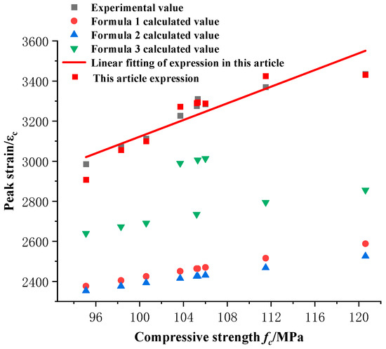
Figure 4.
Relationship between peak strain and axial compressive strength.
4. The Compressive Constitutive Relationship of Steel Slag Micronized UHPC
4.1. Stress–Strain Curves
The stress–strain curves of the specimens were plotted based on the experimental results, as shown in Figure 5. Figure 5a–c show the stress–strain curves of the 1%, 1.5%, and 2% steel fibre content groups, respectively. Each graph has three levels of stress-strain curves and is compared with the P10 group without steel fiber control group.
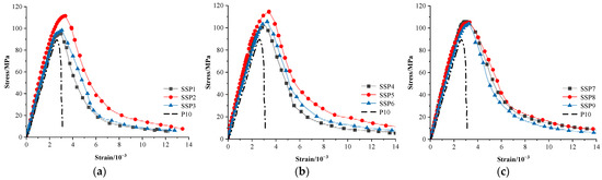
Figure 5.
Stress–strain diagram of steel fibre-doped steel slag micronized UHPC.
Figure 5 illustrates that during the initial loading stage of the test, the specimens were in the elastic phase, and the stress–strain curves exhibited an approximately linear upward trend. Although there were some variations in the slope of each curve, the overall slope increased with an increase in the coarse aggregate content while the steel fibre content remained constant. The curve had the highest slope when the coarse aggregate content was 20%, indicating that an appropriate addition of coarse aggregate can enhance the elastic modulus of steel slag micro-powder UHPC mixed with steel fibre. However, if the coarse aggregate content is increased to 40%, the volume of the cementitious material decreases, and the bond between the coarse aggregates formed by the cementitious material and steel fibres is reduced, leading to an overall decrease in the elastic modulus of the specimens. As the stress on the specimens approached 0.7 to , the slope of the curve gradually decreased, and when the load reached 90% of the ultimate bearing capacity of the specimen, the curve started to level off. For specimens with a constant steel fibre content, when the coarse aggregate content was 40%, the curve showed a shorter plateau segment, and the strain of the specimen was also the lowest among specimens with the same steel fibre content. This indicates that the excessive addition of coarse aggregate to the specimens would reduce the ductility of steel slag micro-powder UHPC.
After reaching the peak stress, the curve entered the descending stage, and the addition of steel fibres and coarse aggregates made the descending stage smoother. Among them, the addition of 20% coarse aggregate content resulted in the smoothest descending stage. Compared with P10 (the group without steel fibres), all nine groups showed a significantly smoother descending stage, indicating a good toughening effect.
The stress–strain relationship model for uniaxial compression of ultra-high-performance concrete proposed in [28] was used for comparison. The model relationship is as follows:
In the equation, represents the stress when the strain of ultra-high-performance concrete reaches ; is the elastic modulus of ultra-high-performance concrete; fc is the design compressive strength of ultra-high-performance concrete; is the standard compressive strength of ultra-high-performance concrete cubes; is the strain corresponding to the peak stress fc of ultra-high-performance concrete; and is the ultimate compressive strain of ultra-high-performance concrete, which is taken as when under axial compression.
The stress–strain relationship calculated using Equation (6) was compared with the experimental values, as shown in Figure 6. Figure 6a–c show a comparison of the 1%, 1.5%, and 2% steel fibre content groups, respectively. Each graph has three experimental stress-strain curves and three calculated curves using specifications for comparison.The slopes of the stress–strain curves obtained from the model in the code were generally greater than those of the experimental curves. The slope of the model curve in the code depends on the actual elastic modulus of ultra-high-performance concrete, indicating that the specimens of steel slag micro-powder UHPC mixed with steel fibre maintained a high level of elastic modulus and excellent deformation resistance.
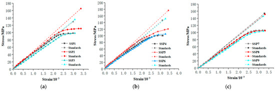
Figure 6.
Comparison between standard and experimental curves.
4.2. Determination of Constitutive Relationship
To establish the constitutive relationship equation for the compressive behaviour of the concrete, different scholars have proposed various constitutive models. In this study, after a comprehensive analysis of different constitutive models, As shown in Table 6, we selected the constitutive equation proposed by the following researchers for comparison in order to find the most suitable formula for expressing the stress–strain relationship of steel fibre-doped steel slag micronized UHPC.
Table 6.
Table of constitutive equation relation.
This experiment uses the dimensionless coordinate . The typical UHPC axial compression stress–strain curve is shown in Figure 7.
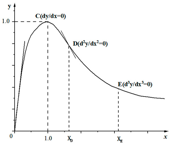
Figure 7.
Typical uniaxial compression stress–strain curve.
Using the three aforementioned models, along with the model proposed in this study, non-dimensionalized nonlinear fitting of the experimentally obtained stress–strain curves was performed, as shown in Figure 8.
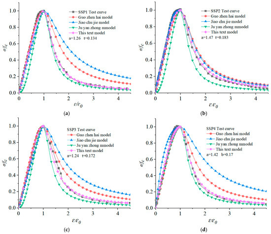
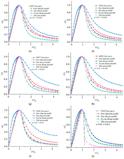
Figure 8.
Comparison of dimensionless nonlinear fitting of stress–strain curves.
- (1)
- The ascending segment of the Guo Zhenhai model exhibited a good fit with the experimental curve, with 1 < < 1.5, while the descending segment displayed a large fitting deviation.
- (2)
- The Jiao Chujie model showed only a few instances of good fit in the ascending segment, with large deviations in other cases, and the stress in the descending segment exceeded that of the experimental curve.
- (3)
- The Ju Yanzhong model underestimated the stress in the ascending segment and exhibited a larger fitting deviation compared to the experimental curve, but it demonstrated a better fit and smaller deviations compared to the previous two models.
Although the ascending segment of the Guo Zhenhai model showed a good fit, the value of parameter a1 did not exhibit a clear relationship with the steel fibre and coarse aggregate content, making it difficult to predict. Therefore, to construct a reasonable constitutive relationship model for the ascending segment of steel slag micronized UHPC under compression, a fourth-degree polynomial equation was fitted. The proposed constitutive model for the ascending segment of steel slag micronized UHPC is given by Equation (10):
As shown in Figure 7, the boundary conditions for the equation are as follows:
The parameters , , , and are undetermined in Equation (10). Substituting Equation (11) into Equation (10),
From the above equation, it can be concluded that and can be represented by , resulting in the following relationship equation:
When , then .
Where is the initial tangent modulus and is the secant modulus at peak stress, both in MPa.
Based on Figure 8, the stress–strain curve of steel slag micronized UHPC can be represented by a piecewise equation, with the proposed model for the ascending segment and the Ju Yanzhong model for the descending segment as follows:
Figure 8 illustrates the fitting results of the model proposed in this study. In Figure 8, a–j plot shows a comparison of the strain curves for the 9 variable trials and the control trials. Each graph has an experimental curve that is compared with the curves of the other three cited scholar models and the model curves in this article.It is evident that the model given by Equation (14) provides a satisfactory fit to the complete stress–strain curve and is more suitable for expressing the constitutive relationship of steel slag micronized UHPC compared to other models.
Based on the fitting results obtained in this study, the relationship equation between the ascending segment parameter and the steel fibre content () and coarse aggregate content () of steel slag micronized UHPC can be derived as follows:
The ascending segment parameter represents the ratio of elastic modulus to secant modulus, indicating the variation in the elastic modulus and the shape of the stress–strain curve in the ascending segment. A higher value of indicates improved ductility of steel fibre-doped steel slag micronized UHPC material.
For the analysis of the descending segment, the parameter t is selected by fitting the Ju Yanzhong model, which reflects the variation in the shape of the stress–strain curve in the descending segment. A smaller value of t suggests a more brittle material. By performing a nonlinear regression analysis between the Ju Yanzhong model and the experimental results, the relationship equation between t and the steel fibre content () and coarse aggregate content () can be established as follows:
According to the results obtained in this article, the ratio of the axial compressive strength of UHPC mixed with steel fibre and steel slag powder to the axial compressive strength of UHPC mixed with ordinary steel slag powder and the substitution relationship between steel fibre and coarse aggregate is
4.3. Simulation Model Establishment and Verification
To validate the rationality of the proposed constitutive relation models in this study, comprehensive nonlinear analysis of prism specimens was conducted using finite element software. Uniaxial compression tests were simulated of fibre-reinforced prisms using finite element software ABAQUS, with an analysis model of 100 mm × 100 mm × 300 mm prism (consistent with the size of the test specimen); the concrete unit was a three-dimensional Hexahedron reduction unit, which was divided by a global grid with a size of 10. In order to prevent the local concrete from being destroyed ahead of time due to stress concentration and to more realistically simulate the actual situation of uniaxial compression, the upper and lower ends of the prism were, respectively, provided with a size of 150 mm × 150 mm × 10 mm rigid pad simulation loading device with elastic modulus set to 2.08 × 10⁵ MPa. The upper and lower ends of the specimen were in contact with the rigid pad through rough friction, and the vertical loading point was coupled with the plane of the rigid pad end. The loading method adopted displacement control loading. The concrete expansion angle was taken as 30 degrees, the eccentricity was 0.1, the ratio of biaxial compressive strength to uniaxial compressive strength was 1.16, the influence parameter of concrete yield form was 0.667, and the viscosity coefficient was 0.005.
In the calculation, the constitutive equation of concrete under compression adopted the above steel fibre-reinforced steel slag powder UHPC uniaxial compression fitting stress–strain curve relationship. The tension stress–strain relationship adopted the Constitutive equation suggested in Appendix C of GB50010-2010 Code for Design of Concrete Structures. The compression inelastic strain and tension cracking strain can be calculated according to the following Equation (18):
where and represent the inelastic strain in compression and the tensile cracking strain, respectively; and are obtained from the uniaxial compressive stress–strain constitutive equation of steel fibre-reinforced steel slag micro powder UHPC mentioned above; and are obtained from [25].
The damage factor d refers to the CDP model damage factor calculation formula proposed by Sidoroff [31]:
where and obtained from the constitutive equation proposed in this article, and is the initial elastic modulus of concrete
In Figure 9a, it can be noted that the simulated prism specimens exhibit the most significant damage in the middle of the side surface, with a radial distribution of damage intensity. Under the applied load, the central region experiences compressive failure first, and some specimens display an “X” pattern of failure, which aligns with the actual experimental observations.
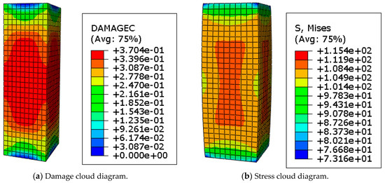
Figure 9.
Simulation model cloud diagram.
In Figure 9b, it can be observed that after loading, the maximum stress and slight expansion deformation occur in the middle of the concrete on both sides of the specimen, while the stress and deformation at the ends of the concrete are relatively small. The stress distribution on the side surface of the specimen demonstrates a radial pattern, which accurately reflects the actual damage scenario.
The partial uniaxial compressive stress–strain simulation curves and experimental curves of UHPC specimens mixed with steel fibre and steel slag powder are shown in Figure 10. It can be seen that the numerical simulation curves and the overall trend of the experimental curves are in good agreement with different fibre contents. After calculation, the peak stress error is only 1.5% to 8%, and the peak strain error is about 2.5% to 10%, both of which are within an acceptable range. This shows that the above constitutive equation is suitable for the plastic damage analysis of steel fibre-reinforced steel slag micro powder UHPC specimens. Overall, the simulated values are slightly lower than the experimental values, and there are instances of curve crossing in some experimental groups. These discrepancies can be attributed to several factors. Firstly, the assumption of rigid contact between the specimen and the base plate during software simulation differs from the ideal hinged support at the ends of the actual experiments. Additionally, variations in the distribution of coarse aggregate and steel fibres within the specimens during fabrication can lead to inconsistencies in the elastic modulus of different parts within the specimens, resulting in some errors in the measured compressive displacement.
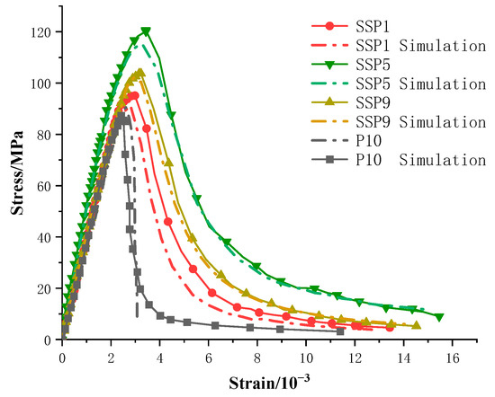
Figure 10.
Comparison of stress–strain curves between simulation and experiment.
In addition, the proportion of cementitious materials, the shape and aspect ratio of steel fibres, and coarse aggregates did not change during the experiment. Therefore, whether the model proposed in the article is suitable for a wider range of parameters needs further experimental verification. When used in engineering, adjustments can be made based on the actual parameter range and material test results. In view of the stability of the chemical composition of steel slag, the steel slag coarse aggregate also has the feasibility of replacing the coarse aggregate in UHPC, which can be confirmed by experiments in the future, which can make the production of Ecotype UHPC have a better prospect.
5. Conclusions
- When the steel fibre content in steel fibre-doped steel slag micronized ultra-high-performance concrete (UHPC) is 1%, the axial compressive strength shows an increasing trend with an increase in coarse aggregate content, followed by a decrease. When the steel fibre content is 2%, the axial compressive strength exhibits a slight decrease with an increase in coarse aggregate content. The optimal combination of steel fibre content and coarse aggregate content for achieving the maximum axial compressive strength and peak strain is 1% and 20%, respectively.
- With a constant steel fibre content, the peak strain of each group of specimens shows an initial increase followed by a decrease as the coarse aggregate content increases. Overall, the peak strain ranges from 2985 to 3435 . Based on the experimental variations in the peak strain and axial compressive strength of steel fibre-doped steel slag micronized UHPC, a relationship equation for peak strain strength is obtained through fitting.
- By analysing the measured experimental data, a uniaxial compressive constitutive relation equation is proposed for steel fibre-doped steel slag micronized UHPC, and the calculation formulae for the related parameter values of the constitutive relation equation are provided. The established constitutive relation curve fits well with the experimental curve, and the calculated values have a deviation within 10% of the measured values. This indicates that the selected constitutive relation equation and parameter calculation formulae are reasonably accurate, providing a reference for strength prediction and practical applications of steel fibre-doped steel slag micronized UHPC.
- Finite element software was used to perform a nonlinear analysis of the entire axial compressive process of prism specimens based on the proposed constitutive relation equation in this study, providing effective supplementary information for the measured values. The calculations show that the finite element simulation curve exhibits a similar trend to the experimental curve, and the deviation in the peak load is within 10%. This further verifies the reliability of the proposed constitutive relation equation.
Author Contributions
Conceptualization, X.T. and B.H.; methodology, B.H.; software, B.H.; validation, X.T., B.H. and J.C.; formal analysis, B.H.; investigation, B.H.; resources, X.T and B.Y.; data curation, B.H.; writing—original draft preparation, B.H.; writing—review and editing, B.H., X.T. and J.C.; visualization, X.T.; supervision, B.Y. and J.C.; project administration, B.Y.; funding acquisition, B.Y. and X.T. All authors have read and agreed to the published version of the manuscript.
Funding
This work was supported by the National Natural Science Foundation of China (No. 42067044) and the Guangxi Graduate Education Innovation Program (YCSW2021171).
Institutional Review Board Statement
Not applicable.
Informed Consent Statement
Not applicable.
Data Availability Statement
The data used to support the findings of this study are available from the corresponding author upon request.
Conflicts of Interest
The authors declare that they have no known competing financial interests or personal relationships that could have appeared to influence the work reported in this paper.
References
- Graybeal, B.; Bruhwiler, E.; Kim, B.-S.; Toutlemonde, F.; Voo, Y.L.; Zaghi, A. International Perspective on UHPC in Bridge Engineering. J. Bridge Eng. 2020, 25, 04020094. [Google Scholar] [CrossRef]
- Shao, X.; Deng, L.; Cao, J. Innovative steel-UHPC composite bridge girders for long-span bridges. Front. Struct. Civ. Eng. 2019, 13, 981–989. [Google Scholar] [CrossRef]
- Hung, C.-C.; El-Tawil, S.; Chao, S.-H. A Review of Developments and Challenges for UHPC in Structural Engineering: Behavior, Analysis, and Design. J. Struct. Eng. 2021, 147, 03121001. [Google Scholar] [CrossRef]
- Hu, R.; Fang, Z.; Shi, C.; Benmokrane, B.; Su, J. A review on seismic behavior of ultra-high performance concrete members. Adv. Struct. Eng. 2021, 24, 1054–1069. [Google Scholar] [CrossRef]
- Tang, X.Y.; Ma, J.L.; Ro, J.; He, B.B.; Lu, C.J. Steel slag micro-powder ecological super high performance concrete mechanical properties analysis. Silic. Bull. 2023, 42, 607–617. (In Chinese) [Google Scholar]
- Chen, C.; Tang, X.; Ma, J.; Tang, Y.; Shen, S.; Chen, R.; Zheng, J. Analysis of Factors Influencing the Compressive Strength of Steel Slag Micronized Ultra-High Performance Concrete Based on Orthogonal Tests. Highway 2023, 68, 328–332. (In Chinese) [Google Scholar]
- Nguyen, T.V.; Le, A.T. A Study on Steel Slag Replacing Sand in Concrete. In Proceedings of the 4th International Conference on Green Technology and Sustainable Development (GTSD), Ho Chi Minh City, Vietnam, 23–24 November 2018; pp. 821–824. [Google Scholar]
- Zhang, H.R.; Ji, T.; Lin, X.Y. Pullout behavior of steel fibres with different shapes from ultra-high performance concrete (UHPC) prepared with granite powder under different curing conditions. Constr. Build. Mater. 2019, 211, 688–702. [Google Scholar] [CrossRef]
- Zhang, L.; Liu, J.; Liu, J.; Zhang, Q.; Han, F. Effect of Steel Fibre on Flexural Toughness and Fracture Mechanics Behavior of Ultrahigh-Performance Concrete with Coarse Aggregate. J. Mater. Civ. Eng. 2018, 30, 04018323. [Google Scholar] [CrossRef]
- Koksal, F.; Sahin, Y.; Gencel, O.; Yigit, I. Fracture energy-based optimisation of steel fibre reinforced concretes. Eng. Fract. Mech. 2013, 107, 29–37. [Google Scholar] [CrossRef]
- Ma, J.; Orgass, M.; Dehn, F.; Schmidt, D.; Tue, N.V. Comparative Investigations on Ultra-High Performance Concrete with or without Coarse Aggregates. In Proceedings of the International Symposium on Ultra High Performance Concrete, Kassel, Germany, 13–15 September 2004; pp. 205–212. [Google Scholar]
- Li, P.P.; Yu, Q.L.; Brouwers, H.J.H. Effect of coarse basalt aggregates on the properties of Ultra-high Performance Concrete (UHPC). Constr. Build. Mater. 2018, 170, 649–659. [Google Scholar] [CrossRef]
- Luo, M.; Lin, P.; Yang, Z. Study of Uniaxial Compressive Mechanical Properties and Intrinsic Structure Relationship of UHPC. Bridge Constr. 2020, 50, 62–67.8. (In Chinese) [Google Scholar]
- Ma, K.; Ma, Y.; Xing, G.; Liu, B. Behavior of ultra-high-performance concrete columns subjected to axial compressive load. Adv. Struct. Eng. 2021, 24, 3792–3808. [Google Scholar] [CrossRef]
- Zeng, X.; Deng, K.; Liang, H.; Xu, R.; Zhao, C.; Cui, B. Uniaxial behavior and constitutive model of reinforcement confined coarse aggregate UHPC. Eng. Struct. 2020, 207, 110261. [Google Scholar] [CrossRef]
- El-Helou, R.G.; Koutromanos, I.; Moen, C.D.; Moharrami, M. Triaxial Constitutive Law for Ultra-High-Performance Concrete and Other Fibre-Reinforced Cementitious Materials. J. Eng. Mech. 2020, 146, 04020062. [Google Scholar] [CrossRef]
- Guo, X.Y.; Kang, J.F.; Zhu, J.S.; Duan, M.H. Corrosion Behavior and Mechanical Property Degradation of Weathering Steel in Marine Atmosphere. J. Mater. Civ. Eng. 2019, 31, 04019181. [Google Scholar] [CrossRef]
- Williams, E.M.; Graham, S.S.; Akers, S.A.; Reed, P.A.; Rushing, T.S. Constitutive property behavior of an ultra-high-performance concrete with and without steel fibres. Comput. Concr. 2010, 7, 191–202. [Google Scholar] [CrossRef]
- Yu, R.; Fan, D.Q.; Shui, Z.H.; Wang, X. Mix design of ultra-high performance concrete based on the theory of particle compactness. ACTA Silic. 2020, 48, 1145–1154. (In Chinese) [Google Scholar]
- Wang, X. Design and Evaluation of Eco-Type Ultra-High Performance Concrete Based on the Most Compact Packing Theory; Wuhan University of Technology: Wuhan, China, 2018. (In Chinese) [Google Scholar]
- T∕CECS 864-2021; Standard for Test Methods of Ultra-High Performance Concret. Beijing, China, 2021. (In Chinese)
- GB/T50081-2019; Concrete Physical and Mechanical Properties Test Method Standards. Beijing, China, 2019. (In Chinese)
- GB50010-20021; Code for Design of Concrete Structures. Ministry of Housing and Urban-Rural Development of the People’s Republic of China: Beijing, China, 2010. (In Chinese)
- Xue, G.; Zhao, Y.; Zhou, H. Experimental Study on Uniaxial Compressive Stress-Strain Relationship of Steel Slag Coarse Aggregate Concrete. Engineeringmechanics 2022, 39, 86–95. (In Chinese) [Google Scholar]
- Guo, Z. Principle of Reinforced Concrete; Tsinghua University Press: Beijing, China, 2013; pp. 13–20. (In Chinese) [Google Scholar]
- Yang, W.Z.; Bai, X.W.; Li, Y. Study of Axial Compression Principal Structure Relationship of High-Strength Concrete. China Concr. Cem. Prod. 2018, 3, 21–24. (In Chinese) [Google Scholar]
- Lu, X.L.; Zhang, Y.; Nian, X.C. Experimental Study of Axial Compressive Stress-Strain Curves of Steel Fibre High-Strength Concrete Under Monotonic and Repetitive Loading. J. Build. Struct. 2017, 38, 135–143. [Google Scholar]
- T/CECS-2021; Technicai specification for application of high performance concrete in building and road engineering. China Planning Press: Beijing, China, 2021. (In Chinese)
- Jiao, C.J.; Sun, W.; Qin, H.G.; Zhang, Y.; Jiang, J. Uniaxial Compressive Principal Structure Equations for Steel Fibre High-Strength Concrete. J. Southeast Univ. (Nat. Sci. Ed.) 2004, 3, 366–369. [Google Scholar]
- Ju, Y.Z.; Wang, D.H.; Li, Q.; Jia, Y.Z.; Xiao, Q. Effect of Steel Fibre Admixture on Mechanical Properties of Activated Powder Concrete. J. Exp. Mech. 2011, 26, 254–260. (In Chinese) [Google Scholar]
- SIDOROFFF. Description of Anisotroopic Damage Application to Elasticity; Springer: Berlin/Heidelberg, Germany, 1981. [Google Scholar]
Disclaimer/Publisher’s Note: The statements, opinions and data contained in all publications are solely those of the individual author(s) and contributor(s) and not of MDPI and/or the editor(s). MDPI and/or the editor(s) disclaim responsibility for any injury to people or property resulting from any ideas, methods, instructions or products referred to in the content. |
© 2023 by the authors. Licensee MDPI, Basel, Switzerland. This article is an open access article distributed under the terms and conditions of the Creative Commons Attribution (CC BY) license (https://creativecommons.org/licenses/by/4.0/).