Article

Modeling Investigation of Groove Effect on the Multipactor of Dielectric-Loaded Coaxial Low-Pass Filters

1
54th Research Institute of CETC, Shijiazhuang 050011, China
2
China Academy of Space Technology, Xi’an 710100, China
*
Author to whom correspondence should be addressed.
Appl. Sci. 2023, 13(15), 8586; https://doi.org/10.3390/app13158586
Submission received: 14 May 2023 / Revised: 11 July 2023 / Accepted: 18 July 2023 / Published: 26 July 2023
(This article belongs to the Section Applied Physics General)

Abstract

:
Multipactor is a common discharge phenomenon occurring in space microwave systems. The surface microstructure has been verified to be effective in mitigating multipactor. In this work, we design a square coaxial low-pass filter (SCLPF) with dielectric sheets loaded to check the multipactor dependence on the structure parameters of the loaded dielectric sheets, and further model groove structures on the sensitive area surface to lower the risk of multipactor. Simulation results indicate that the SCLPF loaded with alumina and PTFE exhibits favorable operational characteristics, and the multipactor threshold is significantly improved after introducing the surface grooves. Then, we investigate the effects of three typical groove parameters, groove depth, groove number, and aspect ratio, on the multipactor threshold of the SCLPF device. The results show that the multipactor threshold rises at first as the groove number and groove depth increase, and then the threshold reaches a saturation status. For a deeper analysis of multipactor, we discuss how the grooves shelter the secondary electrons, and further mitigate the electron avalanche. Furthermore, the mechanisms of threshold saturation under the effect of groove parameters are analyzed in detail, and a contour map for the multipactor threshold of PTFE-loaded SCLPFs is given, which makes significant sense for predicting the multipactor threshold of the devices with its sensitive surface being grooved. The regularity of modulating the multipactor threshold by the groove structures obtained in this study is of engineering significance for suppressing multipactor in microwave devices in practical applications.

1. Introduction

Microwave devices working in the space environment are constantly influenced by the irradiation from the universal rays and particles. The phenomenon of secondary electron emission can be induced when space particles or rays irradiate the material surface. The excited secondary electrons may undergo resonance avalanche multiplication under the action of high-power radio frequency (RF) fields, further inducing the secondary electron avalanche multiplication discharge effect, namely, multipactor [1]. The large number of electrons generated inside the device in a short duration is able to severely interfere with the normal running of the high-power microwave (HPM) systems, and may even cause discharge breakdown [1,2,3,4]. Nowadays, multipactor becomes one of the severe bottleneck problems that obstruct the power increase in microwave devices [4]. Therefore, multipactor threshold is one of the key factors in evaluating the reliability of space HPM systems. There are three essential conditions for the multipactor occurrence, namely, the secondary electron emission yield (SEY) of the irradiated surfaces bigger than 1, the existence of RF fields, as well as, the resonation between secondary electrons and the RF field [1]. Generally speaking, destroying the resonation condition can be considered an effective method to mitigate multipactor [5]. In addition, lowering the SEY of the multipactor sensitive surface can decrease the risk of multipactor since secondary electron avalanche is the direct reason for the multipactor discharge [6,7,8,9]. In other words, a higher SEY always results in a lower multipactor threshold. Currently, the common methods for lowering SEY include coating low-SEY films, such as TiN, TiZrV, and graphene [10,11,12,13,14,15,16], as well as designing surface microstructures to trap the secondary electrons [17,18,19,20].
Alumina and polytetrafluoroethylene (PTFE) have been widely used in high-power microwave systems in space. The multipactor phenomenon for these two dielectric materials has been paid more attention to nowadays since many HPM devices have been developed with dielectric loaded [21,22,23]. In addition, the dielectric materials possess a relatively higher SEY [24,25,26], in order that the multipactor may be easier to be triggered. In recent years, the construction of periodic microstructures on the surface of dielectric materials has received widespread attention and discussion [5,27,28]. These surface microstructures are capable of blocking the movement of secondary electrons while not affecting the normal function of the device, allowing for fewer electrons to participate in the multiplication process.
The current studies involve the multipactor of microstructured surfaces including grooves [29,30], columnar arrays [31,32,33], and porous structures [17,18,19]. Typically, researchers use feature size parameters to quantify these microstructures for discussion. However, scholars are more concerned with a detailed discussion of the secondary electron emission process under microstructures and choose to apply the SEY to predict the ability of the material to suppress multipactor. The relationship between feature size parameters of the microstructure and multipactor threshold is not adequately studied, and the relevant mechanisms still require further discussion. Traditionally, the multipactor threshold relied on charts obtained through experimental studies. However, with the development of particle simulators, accurate predictions can be quickly and conveniently provided.
In this paper, we focus on the groove structure and design a coaxial low-pass filter with dielectric sheets loaded as a test device for multipactor. The filter has an ideal flat gap and perpendicular RF electric field to the surfaces. By simulating the multipactor threshold of alumina and PTFE with different groove sizes, we further obtain the influence regulation of groove depth, groove number, and aspect ratio on the multipactor threshold, and discuss the deep mechanism of how the groove feature sizes affect the multipactor. The obtained discharge data and their underlying regulations will have significant implications for practical engineering applications.

2. Modeling and Simulation Methods

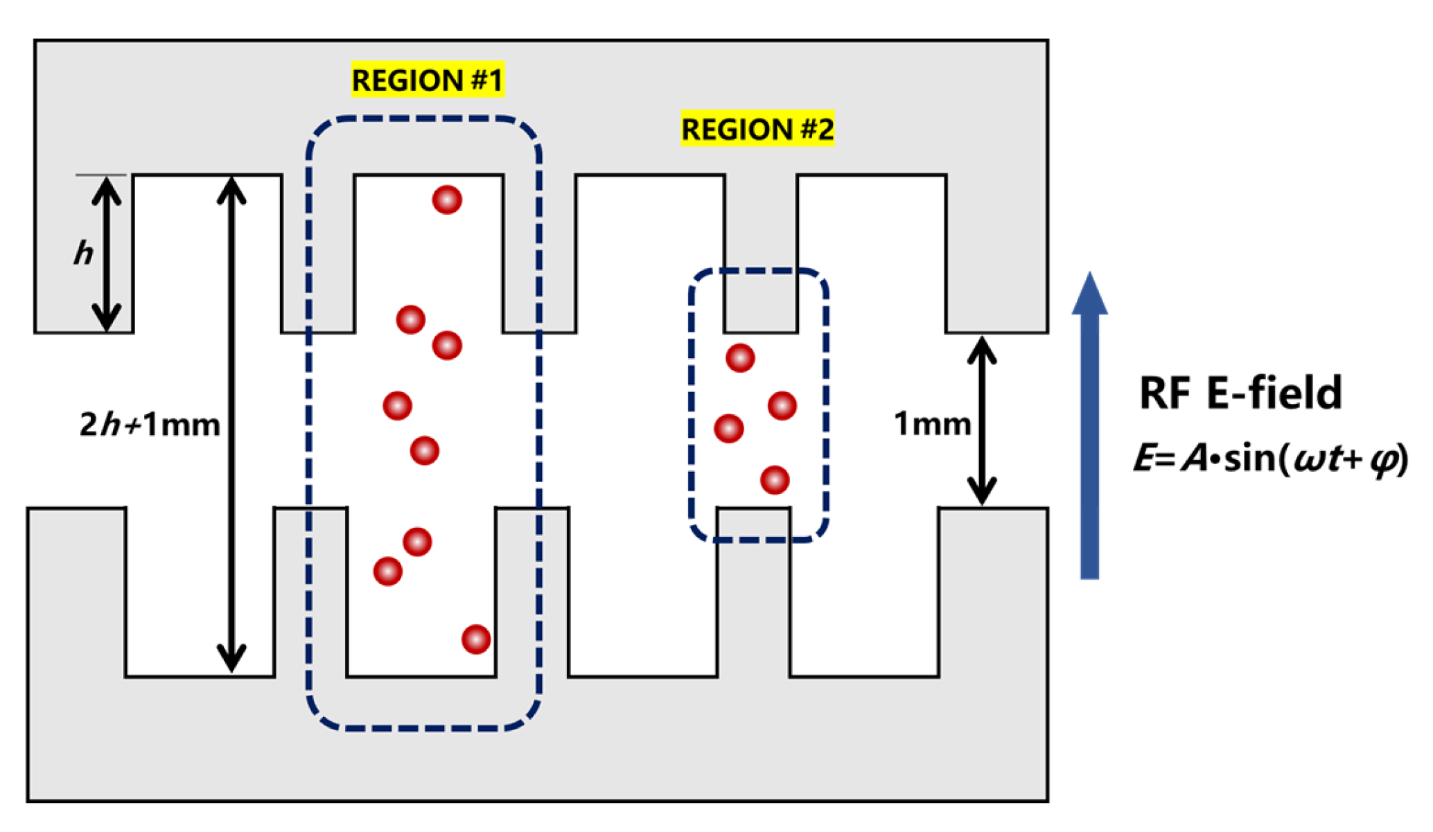
2.1. Design of the Verification Device

Here, we present the design of a square coaxial low-pass filter (SCLPF) that can operate in the L-band. For low-frequency circuits, low-pass or high-pass filters are composed of lumped parameter reactive components (inductors and capacitors). For high-frequency devices, we use microwave structures to simulate lumped parameter elements. This microwave structure can be called a “quasi-lumped element.” The specific design process uses the insertion loss method. First, select the appropriate order (i.e., the number of lumped elements) according to the prototype of the equal-ripple low-pass filter to match the requirements of the filtering performance. Next, according to the normalized element values obtained from the Chebyshev polynomial solution, solve the actual values of the elements using the target cut-off frequency, and obtain the lumped circuit topology. Finally, use the appropriate microwave structure to approximately correspond to the lumped element values one by one to complete the design of the microwave SCLPF [34].
For the SCLPF, the method of approximating the lumped element values of the microwave structure is shown in Figure 1. It illustrates the T-shaped and the ∏-shaped equivalent circuits of the coaxial line, as well as the calculation method of the component values. For the equivalent circuit in (b), if high impedance coaxial lines are connected at both ends of it, due to the small value of the electrical reactance in (b), the equivalent circuit can be further simplified to a separate parallel capacitor. Similarly, the two electrical capacitances with small value in (c) can be ignored when two low impedance coaxial lines are connected at both ends of it. As a result, we can obtain the approximate equivalent structures shown in (d) and (e). With the known values of the lumped circuit elements of the filter, we can apply Formulas (1) and (2) to select appropriate impedance and coaxial line length, where v is the wave speed, l is the length of coaxial line, and w is the angular frequency [35].
B = Y 0 sin ω l v
X = Z 0 sin ω l v
In the actual design process, compromises have to be made sometimes, which depends heavily on the engineer’s practical engineering experience. Here, we use the optimized function of CST software (version number, CST2020) to achieve the preferable size parameters for each part [36].
The aforementioned design method is applicable to various microwave transmission structures, such as circular coaxial, microstrip, rectangular waveguide, etc., as long as their characteristic impedance characteristics are known. For the square coaxial structure operating in the transverse-electromagnetic-wave mode [34], the inner and outer conductors form a parallel plate gap with an electric field perpendicular to the surface. This configuration is particularly suitable for analyzing multipactor phenomena. Therefore, we have chosen the square coaxial structure for this purpose. The SCLPF designed in this article is shown in Figure 2. It is a 13th-order filter with an inner conductor being arranged alternately with rectangular blocks of different side lengths. In the central low-impedance area, there is the narrowest distance between the inner and outer conductors. Extra dielectric sheets are placed in this area to create a gap of 1 mm for checking the multipactor property of the device. In other low-impedance areas, the gaps are filled with PTFE to “block” them, ensuring that multipactor can only occur in the narrowest central section.
Alumina and PTFE are chosen as the dielectric sheets for checking the multipactor threshold in this work. The adoption of different materials will cause slight differences in the device transmission performance; therefore, it is necessary to make brief adjustments to optimize the final size parameters. We designed two sizes of SCLPFs equipped with alumina and PTFE sheets, respectively. They have consistent performance parameters, with only slight differences in the size of the internal conductor segments. In the central low-impedance region, a pair of dielectric sheets are placed on the top surface of the inner conductor and the bottom surface of the outer conductor, separately. The size of the alumina sheets is 8 × 5 × 0.25 mm3, and the size of PTFE is 8 × 6.5 × 0.5 mm3. The frequency response in Figure 3 shows that two SCLPFs loaded with different dielectrics can achieve good transmission performance, thereinto, the insertion loss is less than 0.1 dB, and the return loss is generally greater than 20 dB from 1.5 to 5 GHz. The simulation results also indicate that the electric field between the dielectric sheets can reach nearly 6000 V/m. Therefore, the gap will experience multipactor first with the increase in input power since the region possesses the largest electric field and the narrowest gap.

2.2. Multipactor Simulation for the SCLPF with Flat Dielectric Loaded

We use SPARK3D to achieve the simulation of multipactor. SPARK3D is a module in CST that simulates the secondary electron multiplication discharge characteristics of passive devices, such as waveguides, microstrips, and antennas. The SPARK3D module employs the Monte Carlo method and 3D electron tracking model to solve for the electron number in the device-defined region. Therefore, SPARK3D can calculate the maximum operating power of the device without multipactor, which is defined as the multipactor threshold. Some reports of multipactor studies using SPARK3D [37,38] and an introduction to the SPARK3D software (version number, CST2020) [39] are given in the literature and the Supplementary Materials.
We built and calculated the device model shown in Figure 2 using CST Microwave Studio. We obtained the distributions of the electric field and magnetic field of the SCLPF at a working frequency of 1.5 GHz. The simulation area shown in Figure 2 is defined as the sensitive region. We set the SEY of each surface within the area and randomly injected 1500 initial seed electrons into the area to simulate the free electrons in the microwave cavity of the spacecraft device. The initial simulation power is 500 W. When this power leads to secondary electron multiplication and breakdown, the software will reduce the input power by half and restart the simulation. On the contrary, if the input power does not result in breakdown, the average of this power and the nearest breakdown power is calculated, and the simulation is repeated until the final result gradually approaches the actual multipactor threshold.
We employ the SEY data of the primitive alumina [40] and PTFE [41] sheets into SPARK3D. The SEY peak values of alumina and PTFE are 3.60 and 2.04, respectively. The simulation results are shown in Figure 4. As we can conclude from Figure 4, the multipactor threshold values of the SCLPFs with flat alumina loaded and PTFE loaded are 137.69 W and 347.63 W, respectively.

3. Simulation Verification

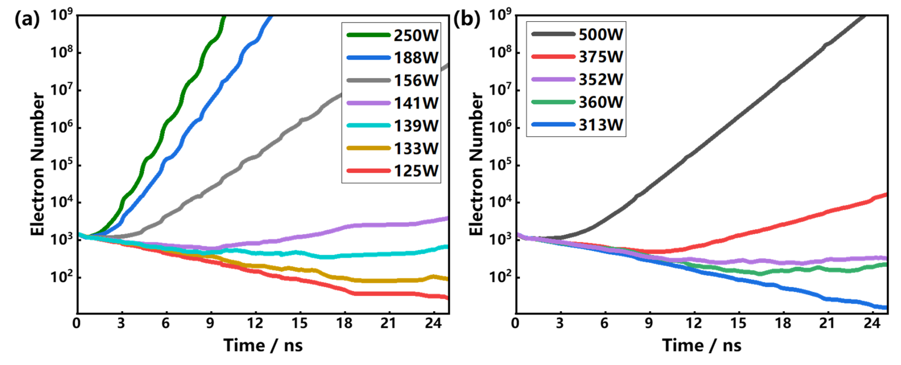
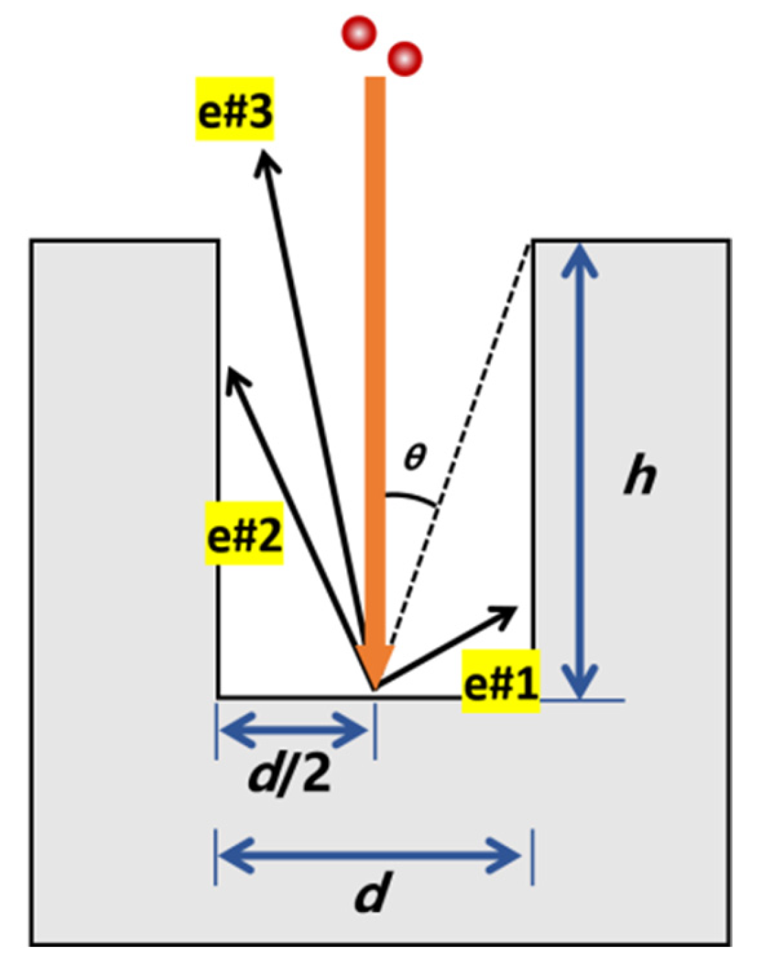
3.1. The Groove Effect on the Multipactor Threshold

For the purpose of quantifying the groove effect on multipactor, we investigate the variation tendency of multipactor threshold by constructing groove structures on the dielectric sheets. Along the transmission direction of the microwave, the alumina sheets are divided into several cells by every 0.5 mm, a rectangular groove with sizes of 0.25 mm width and 0.2 mm depth is created in each cell, as shown in Figure 5a. Here, we define the ratio of the groove projected area to the total cell area as the groove ratio, which can be expressed as d/w in Figure 5c. According to this definition, the groove ratio in Figure 5a is 50%. Similar model construction of grooves is also carried out on PTFE sheets. Via the CST simulation, we discover that the groove structure is able to increase the electric field since the grooves provide several right-angle structures, and further cause local enhancement of the electric field due to the complex non-uniform structure. To make the process of multipactor less affected by the variation of the electric field, here, we shortened the groove length to 7.6 mm and left a 0.2 mm margin on two sides. Figure 5b,d show the shape of the grooves after modification, and it can be seen that the groove ratio becomes 47.5%.
Figure 6 shows the simulation results of the electron number evolution when the grooved dielectric (alumina and PTFE) sheets are loaded in the SCLPFs. By analyzing the results, the multipactor threshold of 240.23 W for the SCLPF with grooved alumina loaded is acquired, and 727 W for the SCLPF with grooved PTFE loaded is obtained. Compared to the original multipactor threshold values in Figure 4, 137.69 W for alumina-loaded device and 347.63 W for PTFE-loaded device, it can be concluded that the grooved sheets are able to improve the multipactor threshold remarkably despite the material type.

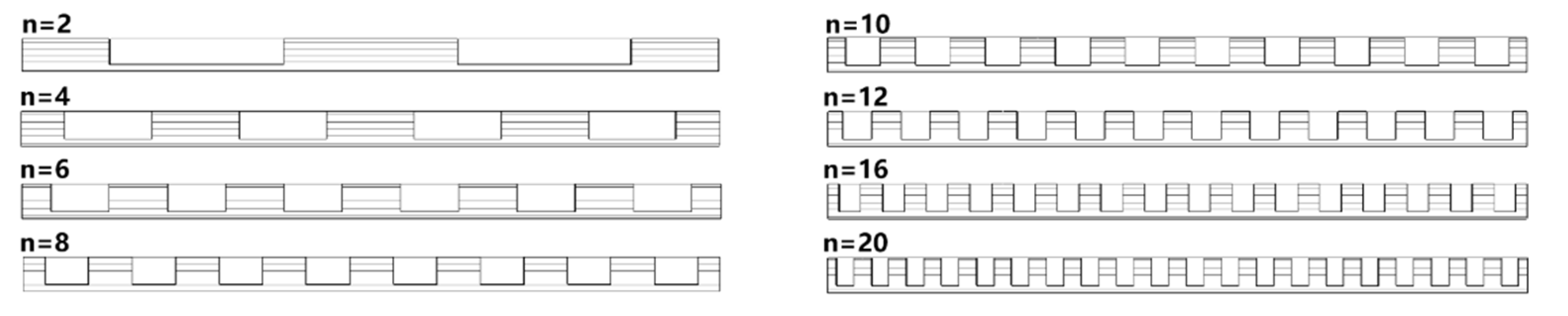
3.2. The Effect of Groove Number on the Multipactor Threshold

In this section, the SCLPFs loaded with the alumina sheets are employed to check how the groove number affects the multipactor threshold. As shown in Figure 7, we set various groove numbers, n, on the loaded alumina sheets. The length of the grooves is 7.6 mm, the depth is 0.2 mm, and the groove ratio in each cell is 47.5%.
The multipactor simulation results are shown in Figure 8. From Figure 8, we know that the multipactor threshold values of all the SCLPFs with grooved alumina sheets loaded show a clear improvement compared to the SCLPFs with flat alumina sheets loaded. Moreover, the multipactor threshold increases as the groove number increases. Simply, when the groove number is greater than 10, the raised magnitude of the multipactor threshold declines as the groove number increases, showing a quasi-saturation status. The threshold stays at around 250 W when the groove number reaches 20, in this case, further increasing the groove number no longer improves the multipactor threshold.

3.3. The Effect of Groove Depth on the Multipactor Threshold

In this section, the SCLPFs loaded with the PTFE sheets are employed to check how the groove depth affects the multipactor threshold. As mentioned in Figure 5, we construct groove structures on the surface of PTFE sheets, the groove number is set as 13, and the length and width of these grooves are set as 7.6 mm and 0.25 mm, respectively. Under the circumstances, the simulation is implemented to obtain the multipactor threshold of the PTFE-loaded SCLPFs as the groove depth increases from 0.02 to 0.48 mm, the simulation results are shown in Figure 9. From Figure 9, we can see that the multipactor threshold increases linearly as the groove depth increases linearly when the groove depth is smaller than 0.45 mm. However, the threshold shows a decline as the groove depth extends beyond 0.45 mm. In this case, the maximum of the multipactor threshold is about 1150 W when the groove depth is 0.45 mm.
The simulation results of this section and the previous section indicate that the multipactor threshold will be remarkably improved as the groove number or depth increases. Moreover, the multipactor threshold may reach a saturation status when the groove number or depth increases to a certain value. The phenomenon can be explained as follows. For the SCLPFs loaded with flat dielectric sheets, there are plenty of secondary electrons emitted from the surface after one incident event during the process of multipactor. Whereas the emission of secondary electrons is changed after introducing the groove structure on the dielectric surface; the groove plays the role of shelter to increase the collision probability of the secondary electrons, and further prevents the emission of secondary electrons, which weakens the risk of multipactor from the source.
To be specific, Figure 10 shows the circumstances of electrons impact on the central position of the bottom of a 2D groove. In this model, there is no need to focus on the interaction processes between electrons and material surfaces. Instead, we only need to consider the trajectory of electron motion to explore the specific mechanisms of microstructure impeding electron movement. In Figure 10, e#1, e#2, and e#3 are three secondary electrons produced by the incident electron, and they are probable to be captured by the sidewall and have less chance to participate in the process of multipactor discharge. In Figure 10, e#1 and e#2 are captured by the sidewall, only e#3 can escape from the groove since its emission polar angle is smaller than θ, which depends on the aspect ratio (h/d). When the groove number or the groove depth increases, the aspect ratio will increase and θ will decrease accordingly. In this process, more electrons will impact the sidewall, and the multipactor process can be weakened. As for the reason for saturation, it can be seen that when the groove narrows linearly or the depth increases linearly, θ will decrease and the rate of decrease gradually slows down. Although the number of electrons captured by the sidewall will also increase, the increase is extremely slow, and the suppression of multipactor tends to be saturated.

3.4. The Effect of Multiple Factors on the Multipactor Threshold

Via the analysis in Section 3.1Section 3.3, it is clear that the groove aspect ratio, the groove number, and the groove depth do not affect the multipactor threshold independently. Therefore, it is needed to focus on the combined effect of these factors on the multipactor threshold. Here, we arrange the simulations for the SCLPFs with the grooved PTFE sheets loaded. The simulation results are shown in Table 1, with different groove numbers and aspect ratios. Figure 11 shows the contour map that describes the relationship among multipactor threshold, groove number, and aspect ratio. The groove depth is 0.5 mm, the number of grooves is set as 3, 7, 13, 20, and 26, as well as the aspect ratios vary from 0.1 to 3.9. It ought to be mentioned here that a smaller groove number cannot achieve a large aspect ratio since the small groove number implies a larger groove width, and it is limited by the groove depth of 0.5 mm. High aspect ratio grooves can only be achieved when the groove is narrow.
From Table 1 and Figure 11, three conclusions can be summarized. First, as the aspect ratio increases (keep the groove number constant), the multipactor threshold will increase and exceed 1100 W except for the condition that the groove number equals 3. Second, as the groove number increases (keep the aspect ratio constant), the multipactor threshold decreases. Third, different aspect ratios and groove numbers may achieve similar effects in multipactor mitigation. For example, the SCLPF possessing 7 grooves and 0.5 aspect ratio, has a similar multipactor threshold to the SCLPF possessing 20 grooves with 1 aspect ratio.
Figure 11 reflects the combined effect of aspect ratio and groove number on the multipactor threshold and its saturation status. According to Table 1, the SCLPF with 26 grooves, which can achieve a larger aspect ratio at the depth of 0.5 mm, benefits more from a narrower groove compared with the SCLPF with 7 grooves. However, a larger aspect ratio did not significantly improve the saturation value. To be specific, keeping the depth as 0.5 mm, then the saturation multipactor threshold of the SCLPF with 7 grooves and 1 aspect ratio is 1133 W, and that of the SCLPF with 26 grooves and 3.9 aspect ratio is 1137 W. The former device achieves the same multipactor suppression effect as the latter one with fewer grooves and a smaller aspect ratio. Furthermore, from Figure 11, it can be observed that the threshold saturation appears when the groove aspect ratio exceeds 1.5. Thereafter, the rise of the aspect ratio will not result in a further increase for multipactor threshold.
Then, we discuss the influence of groove number on the multipactor threshold of the SCLPFs. During the analysis, if we keep the aspect ratio constant, the groove depth becomes shallower as the groove number increases. Figure 12 shows the two groove structures with the same aspect ratio but different groove numbers. In this case, the electron number colliding with the sidewall above the critical angle θ (the triangular area below the dashed line) is the same regardless of the number of grooves.
Theoretically speaking, the same aspect ratio should have a consistent multipactor suppression effect, but the simulation results shown in Table 1 do not support this prediction. Therefore, it is needed to reconsider the significance of groove depth when analyzing the multipactor threshold. The details of the grooved dielectric sheets filled in the SCLPFs are shown in Figure 13. As detailed in the drawing in Figure 13, the gap of REGION #2 remains at 1 mm, while the gap between the grooves in REGION #1, which is determined by the groove depth, increases greatly. The increase in the average gap cannot be ignored. According to the Hatch–Williams constant k model [42], it can be known that an increase in the gap means there will be more orders, which refers to the number of half cycles that the electron moves from one plane to another. At the same time, the threshold voltage will be higher, and the process of doubling is more difficult to establish, namely, the multipactor threshold is increased. It also ought to be mentioned here that, in addition to suppressing discharge by blocking electron path through the grooves, the passive increase in the gap between 47.5% of the areas is an important reason for mitigating multipactor. Taking the aspect ratio of 0.5 as an example, the multipactor threshold decreases from 710 W to 480 W when the groove number increases from 7 to 26. Correspondingly, the groove depth decreases from 0.23 mm to 0.0625 mm, namely, the gap distance at the groove decreases from 1.46 mm to 1.125 mm. However, for situations with fewer grooves, this rule may not apply. For example, the multipactor threshold of 3 grooves with an aspect ratio of 0.2 is 441.39 W, which is lower than that of 7 grooves, even though the former has a deeper depth. This indicates that the effect of depth on multipactor is also regulated by the number of grooves under the same aspect ratio.
Referring to the contour map shown in Figure 11, it is known that the selection of the groove number and the aspect ratio is partly free to achieve the same effect on increasing the multipactor threshold. This allows the designers to choose different parameters for realizing the mitigation of multipactor free. Simply, more influence factors should be considered for suppressing multipactor between metal surfaces, which is different from that for dielectric surfaces. Specifically, for the multipactor induced by the electron avalanche between two metallic boundaries, the skin effect at high-frequency microwaves concentrates the current on the metal surface, in this case, constructing deeper grooves to suppress the discharge induced by the secondary electron avalanche will affect the transmission performance of the devices. Under the circumstances, increasing the groove number and reducing the groove depth is a better solution. There are similar selection problems for the multipactor induced by the electron avalanche between two dielectric boundaries. On the other hand, for microwave devices loaded with dielectrics, constructing grooves on the dielectric is a subtractive processing method. The volume of the dielectric is reduced after subtractive processing, and the dielectric loss is correspondingly reduced, resulting in a slight reduction in the insertion loss of the device. Under the circumstances, intentionally increasing the subtractive volume within a suitable range can bring benefits to the improvement of transmission performance, which is a preferable choice. Therefore, suppressing multipactor through microstructures is a system engineering. Combining the saturation status discussed in Section 3.2 and Section 3.3, the research on the saturation pattern has strong engineering significance. This means that we should quickly estimate better cost-effectiveness of the groove preparation scheme based on the saturation pattern and contour maps.

4. Conclusions

In conclusion, a kind of SCLPF with dielectric sheets loaded has been designed for checking the influence of surface microstructure on the multipactor threshold. The device possesses a 1 mm gap at the middlemost position, in which the vertical RF electric field reaches the maximum, serving as the multipactor sensitive region. Alumina and PTFE have been chosen as the loaded dielectric sheets for partly filling the narrow gap, and a surface groove structure has been constructed to verify the effect of microstructure on electron avalanche. The simulation work indicates that the transmission characteristics of the SCLPFs are little affected by introducing groove structures on the dielectric surface. The influence of groove depth, groove number, and aspect ratio on the multipactor threshold has been discussed. The results show that constructing grooves is an effective method to improve the multipactor threshold, and it is found that there is a saturation effect for the multipactor threshold as the groove depth and aspect ratio increase. By analyzing the mechanism of the phenomenon, it is found that the three feature parameters of the groove, namely, groove depth, groove number, and aspect ratio, have a combined modulation effect on the multipactor threshold, and several rules are summarized to further explain the saturation effect. The quantitative study shows that a groove structure with high-density, large aspect ratio grooves is able to increase the multipactor threshold of the original PTFE-loaded SCLPF device from ~300 W to ~1100 W. The contour map obtained has practical significance for developing the surface microstructure to raise the multipactor threshold for microwave devices, and the work makes engineering sense for improving the reliability of space microwave systems.

Supplementary Materials

The following supporting information can be downloaded at: https://www.mdpi.com/article/10.3390/app13158586/s1.

Author Contributions

Conceptualization, J.S. and W.Z.; methodology, J.S. and Y.Z.; software, W.Z. and B.S.; validation, J.S. and D.W.; investigation, B.S., Y.L., and T.S.; data curation, J.S. and J.Z.; writing—original draft preparation, J.S. and W.Z.; writing—review and editing, Y.Z. and W.Z.; visualization, Y.Z. and Y.L.; supervision, W.Z.; project administration, T.S. and X.Z.; funding acquisition, W.T. All authors have read and agreed to the published version of the manuscript.

Funding

This research received no external funding.

Institutional Review Board Statement

Not applicable.

Informed Consent Statement

Not applicable.

Data Availability Statement

All data included in this study are available upon request by contact with the corresponding author.

Conflicts of Interest

The authors declare no conflict of interest.

References

  1. Vaughan, J.R.M. Multipactor. IEEE Trans. Electron Devices 1988, 35, 1172–1180. [Google Scholar] [CrossRef]
  2. Lara, J.; Perez, F.; Alfonseca, M.; Galan, L.; Montero, I.; Roman, E.; Garcia-Baquero, D.R. Multipactor prediction for on-board spacecraft RF equipment with the MEST software tool. IEEE Trans. Plasma Sci. 2006, 34, 476–484. [Google Scholar] [CrossRef]
  3. Dong, Y.; Liu, Q.X.; Pang, J.; Zhou, H.J.; Dong, Z.W. Influence of secondary electron yield of material on two-sided multipactor discharge in cavity. Acta Phys. Sin. 2018, 67, 037901. [Google Scholar] [CrossRef]
  4. Raboso, D. Multipactor breakdown: Present status and where are we heading. In Proceedings of the 6th International Workshop on Multipactor Corona and Passive Intermodulation, Valencia, Spain, 1 September 2008. [Google Scholar]
  5. Chang, C.; Liu, Y.S.; Verboncoeur, J.; Chen, C.H.; Guo, L.T.; Li, S.; Wu, X.L. The effect of periodic wavy profile on suppressing window multipactor under arbitrary electromagnetic mode. Appl. Phys. Lett. 2015, 106, 014102. [Google Scholar] [CrossRef]
  6. Fil, N.; Belhaj, M.; Hillairet, J.; Puech, J. Multipactor threshold sensitivity to total electron emission yield in small gap waveguide structure and TEEY models accuracy. Phys. Plasmas 2016, 23, 123118. [Google Scholar] [CrossRef]
  7. Geng, R.L.; Padamsee, H.; Shemelin, V. Multipacting in a Rectangular Waveguide. In Proceedings of the 2001 Particle Accelerator Conference (Cat. No.01CH37268), Chicago, IL, USA, 18–22 June 2001; pp. 1228–1230. [Google Scholar] [CrossRef] [Green Version]
  8. Riyopoulos, S. Multipactor with electric field retarding secondary emission. Phys. Plasmas 1998, 5, 305–311. [Google Scholar] [CrossRef]
  9. Hueso, J.; Vicente, C.; Gimeno, B.; Boria, V.E.; Marini, S.; Taroncher, M. Multipactor Effect Analysis and Design Rules for Wedge-Shaped Hollow Waveguides. IEEE Trans. Electron Devices 2010, 57, 3508–3517. [Google Scholar] [CrossRef] [Green Version]
  10. Wang, D.; He, Y.N.; Cui, W.Z. Secondary electron emission characteristics of TiN coatings produced by RF magnetron sputtering. J. Appl. Phys. 2018, 124, 053301. [Google Scholar] [CrossRef]
  11. Pimpec, F.L.; Kirby, R.E.; King, F.; Pivi, M. Properties of TiN and TiZrV thin film as a remedy against electron cloud. Nucl. Instrum. Methods Phys. Res. Sect. A Accel. Spectrometers Detect. Assoc. Equip. 2005, 551, 187–199. [Google Scholar] [CrossRef]
  12. Henrist, B.; Hilleret, N.; Scheuerlein, C.; Taborelli, M. The secondary electron yield of TiZr and TiZrV non-evaporable getter thin film coatings. Appl. Surf. Sci. 2001, 172, 95–102. [Google Scholar] [CrossRef] [Green Version]
  13. Le Pimpec, F.; Kirby, R.E.; King, F.K.; Pivi, M. The effect of gas ion bombardment on the secondary electron yield of TiN, TiCN and TiZrV coatings for suppressing collective electron effects in storage rings. Nucl. Instrum. Methods Phys. Res. Sect. A Accel. Spectrometers Detect. Assoc. Equip. 2006, 564, 44–50. [Google Scholar] [CrossRef] [Green Version]
  14. Pinto, P.C.; Calatroni, S.; Neupert, H.; Letant-Delrieux, D.; Edwards, P.; Chiggiato, P.; Taborelli, M.; Vollenberg, W.; Yin-Vallgren, C.; Colaux, J.L.; et al. Carbon coatings with low secondary electron yield. Vacuum 2013, 98, 29–36. [Google Scholar] [CrossRef] [Green Version]
  15. Wang, J.; Wang, Y.; Xu, Y.H.; Zhang, Y.X.; Zhang, B.; Wei, W. Secondary electron emission characteristics of graphene films with copper substrate. Chin. Phys. C 2016, 40, 117003. [Google Scholar] [CrossRef]
  16. Cao, M.; Zhang, X.S.; Liu, W.H.; Wang, H.G.; Li, Y.D. Secondary electron emission of graphene-coated copper. Diam. Relat. Mater. 2017, 73, 199–203. [Google Scholar] [CrossRef]
  17. Ye, M.; He, Y.N.; Wang, R.; Hu, T.C.; Zhang, N.; Yang, J.; Cui, W.Z.; Zhang, Z.B. Suppression of secondary electron emission by micro-trapping structure surface. Acta Phys. Sin. 2014, 63, 147901. [Google Scholar] [CrossRef]
  18. Wang, D.; Ye, M.; Feng, P.; He, Y.N.; Cui, W.Z. An effective reduction on secondary electron emission yield of gold coated surfaces by laser etching. Acta Phys. Sin. 2019, 68, 067901. [Google Scholar] [CrossRef]
  19. Nistor, V.; González, L.A.; Aguilera, L.; Montero, I.; Galan, L.; Wochner, U.; Raboso, D. Multipactor suppression by micro-structured gold/silver coatings for space applications. Appl. Surf. Sci. 2014, 315, 445–453. [Google Scholar] [CrossRef]
  20. Valizadeh, R.; Malyshev, O.B.; Wang, S.; Zolotovskaya, S.A.; Gillespie, W.A.; Abdolvand, A. Low secondary electron yield engineered surface for electron cloud mitigation. Appl. Phys. Lett. 2014, 105, 231605. [Google Scholar] [CrossRef]
  21. Cummings, K.A.; Risbud, S.H. Dielectric materials for window applications. J. Phys. Chem. Solids 2000, 61, 551–560. [Google Scholar] [CrossRef]
  22. Vague, J.; Melgarejo, J.C.; Guglielmi, M.; Boria, V.E.; Anza, S.; Vicente, C.; Rocio, M.M.; Maria, M.; Benito, G.M.; Raboso, D. Multipactor Effect Characterization of Dielectric Materials for Space Applications. IEEE Trans. Microw. Theory Tech. 2018, 66, 3644–3655. [Google Scholar] [CrossRef]
  23. Li, Y.; Wang, D.; Yu, M.; He, Y.N.; Cui, W.Z. Experimental Verification of Multipactor Discharge Dynamics Between Ferrite Dielectric and Metal. IEEE Trans. Electron Devices 2018, 65, 4592–4599. [Google Scholar] [CrossRef]
  24. Zhu, X.; Guo, J.J.; Li, X.X.; Zhou, R.D.; Wang, D.; Zhao, W. Evolvement Investigation of Secondary Electron Emission for Ultrathin MgO Coatings Prepared by Atomic Layer Deposition. Appl. Sci. 2021, 11, 4801. [Google Scholar] [CrossRef]
  25. Cao, W.W.; Wang, B.; Yang, Y.; Zhu, B.L.; Guo, J.J.; Xu, P.; Bai, X.H.; Qin, J.J.; Wang, C.; Zhu, J.P.; et al. Secondary electron emission characteristics of the Al2O3/MgO double-layer structure prepared by atomic layer deposition. Ceram Int. 2021, 47, 9866–9872. [Google Scholar] [CrossRef]
  26. Suharyanto, Y.; Yamano, S.; Kobayashi, S.; Michizono, S.; Saito, Y. Secondary electron emission and surface charging evaluation of alumina ceramics and sapphire. IEEE Trans. Dielectr. Electr. Insul. 2006, 13, 72–78. [Google Scholar] [CrossRef]
  27. Wang, D.; Mao, Z.S.; Ye, Z.; Cai, Y.H.; Li, Y.; He, Y.N.; Qi, K.C.; Xu, Y.N.; Jia, Q.Q. Ultralow electron emission yield achieved on alumina ceramic surfaces and the application in multipactor suppression. J. Phys. D Appl. Phys. 2022, 55, 455301. [Google Scholar] [CrossRef]
  28. Meng, X.C.; Wang, D.; Cai, Y.H.; Ye, Z.; He, Y.N.; Xu, Y.N. Secondary electron emission suppression on alumina surface and its application in multipactor suppression. Acta Phys. Sin. 2023, 72, 107901. [Google Scholar] [CrossRef]
  29. Pivi, M.; King, F.K.; Kirby, R.E.; Raubenheimer, T.O.; Stupakov, G.; Le Pimpec, F. Sharp reduction of the secondary electron emission yield from grooved surfaces. J. Appl. Phys. 2008, 104, 104904. [Google Scholar] [CrossRef]
  30. Vague, J.J.; Asensio, I.; Coves, A.; San Blas, A.A.; Reglero, M.; Pantaleoni, A.V.; Raboso, D.; Baquero-Escudero, M.; Boria, V.E. Study of the Multipactor Effect in Groove Gap Waveguide Technology. IEEE Trans. Microw. Theory Tech. 2022, 70, 2566–2578. [Google Scholar] [CrossRef]
  31. Swanson, C.; Kaganovich, I.D. Modeling of reduced effective secondary electron emission yield from a velvet surface. J. Appl. Phys. 2016, 120, 213302. [Google Scholar] [CrossRef] [Green Version]
  32. Swanson, C.; Kaganovich, I.D. “Feathered” fractal surfaces to minimize secondary electron emission for a wide range of incident angles. J. Appl. Phys. 2017, 122, 043301. [Google Scholar] [CrossRef] [Green Version]
  33. Swanson, C.; Kaganovich, I.D. Modeling of reduced secondary electron emission yield from a foam or fuzz surface. J. Appl. Phys. 2018, 123, 023302. [Google Scholar] [CrossRef] [Green Version]
  34. Matthaei, G.; Young, L.; Jones, E.M. Microwave Filters, Impedance-Matching Networks, and Coupling Structures; Artech House: Norwood, MA, USA, 1980. [Google Scholar]
  35. David, M.P. Microwave Engineering, 4th ed.; John Wiley & Sons, Inc.: Hoboken, NJ, USA, 2012. [Google Scholar]
  36. Automatic Optimization|CST. Available online: https://www.3ds.com/products-services/simulia/products/cst-studio-suite/optimization/ (accessed on 10 July 2023).
  37. Christopher, M.K.; Charlotte, B.; Hsueh-Yung, C. Multipaction Breakdown Simulation of Mated Coaxial Assemblies Utilizing Heterogeneous SEY Boundaries. In Proceedings of the International Workshop on Multipactor, Corona and Passive Intermodulation, Valencia, Spain, 19–21 October 2022. [Google Scholar]
  38. Stephen, A.S.; Preston, T.P. Measurement and Simulation of Partially-Unseated TNC Multipactor Thresholds. In Proceedings of the International Workshop on Multipactor, Corona and Passive Intermodulation, Valencia, Spain, 19–21 October 2022. [Google Scholar]
  39. Spark3D. Available online: https://www.3ds.com/products-services/simulia/products/spark3d/ (accessed on 10 July 2023).
  40. Guo, J.J.; Wang, D.; Xu, Y.T.; Zhu, X.P.; Wen, K.L.; Miao, G.H.; Cao, W.W.; Si, J.H.; Lu, M.; Guo, H.T. Secondary electron emission characteristics of Al2O3 coatings prepared by atomic layer deposition. AIP Adv. 2019, 9, 095303. [Google Scholar] [CrossRef] [Green Version]
  41. Cai, Y.H.; Wang, D.; Zhang, W.; He, Y.N. Seesaw-type modulation of secondary electron emission characteristics of polytetrafluoroethylene-MgO composite coating. J. Vac. Sci. Technol. B 2022, 40, 044001. [Google Scholar] [CrossRef]
  42. Hatch, A.J.; Williams, H.B. The secondary electron resonance mechanism of low-pressure high-frequency gas breakdown. J. Appl. Phys. 1958, 25, 417–423. [Google Scholar] [CrossRef]
Figure 1. (a) An approximate lumped element circuit of the coaxial line; (b,c) two equivalent circuits with corresponding formulas; (d,e) represent further simplified circuit models.
Applsci 13 08586 g001
Figure 2. (a) The 3D model of the designed SCLPF, (b) the cross-section image of the SCLPF.
Applsci 13 08586 g002
Figure 3. Simulated frequency responses of SCLPFs with (a) alumina loaded and (b) PTFE loaded.
Applsci 13 08586 g003
Figure 4. The simulated evolution of electron number for the SCLPFs with (a) flat alumina loaded and (b) flat PTFE loaded.
Applsci 13 08586 g004
Figure 5. The groove structures (a) with and (b) without margins on alumina substrates. Schematic models of grooves (c) with and (d) without margins on dielectric substrates.
Applsci 13 08586 g005aApplsci 13 08586 g005b
Figure 6. The simulated evolution of electron number for the SCLPFs with (a) grooved alumina loaded and (b) grooved PTFE loaded.
Applsci 13 08586 g006
Figure 7. A series of grooves with different sizes on the alumina sheet, with the same groove depth and groove density but different groove numbers.
Applsci 13 08586 g007
Figure 8. The effect of groove number on the multipactor threshold of the alumina-loaded SCLPFs.
Applsci 13 08586 g008
Figure 9. The effect of groove depth on the multipactor threshold of the PTFE-loaded SCLPFs.
Applsci 13 08586 g009
Figure 10. Schematic model of the motion of secondary electrons excited by electrons incident on the center in a 2D groove.
Applsci 13 08586 g010
Figure 11. Contour map of the PTFE-loaded SCLPFs multipactor threshold, with aspect ratio and groove number as coordinate axes.
Applsci 13 08586 g011
Figure 12. Microstructures with the same aspect ratio and groove ratio but different numbers of grooves. (a) four grooves. (b) two grooves.
Applsci 13 08586 g012
Figure 13. The symmetrical groove structure leads to an increase in the average spacing of the gap. REGION #2 achieves a larger multipactor threshold compared to REGION #1.
Applsci 13 08586 g013
Table 1. Simulated multipactor threshold (W) of the PTFE-loaded SCLPFs with various aspect ratios and groove numbers.
Groove NumberAspect Ratio
0.10.20.40.50.811.633.53.9
3417.95441.39568.33
7/472.64/710.89960.911132.79
13/425.76/558.58738.25851.531095.24
20/415.61/509.37628.88718.72984.301164.04
26378.89400.77/484.36//955.06/1160.101136.66
Disclaimer/Publisher’s Note: The statements, opinions and data contained in all publications are solely those of the individual author(s) and contributor(s) and not of MDPI and/or the editor(s). MDPI and/or the editor(s) disclaim responsibility for any injury to people or property resulting from any ideas, methods, instructions or products referred to in the content.

