Communication

Real-Time Information Fusion System Implementation Based on ARM-Based FPGA

1
Institute of Electrical and Computer Engineering, National Yang Ming Chiao Tung University, Hsinchu 30010, Taiwan
2
Industrial Technology Research Institute, Hsinchu 30010, Taiwan
3
Institute of Electrical and Control Engineering, National Yang Ming Chiao Tung University, Hsinchu 30010, Taiwan
*
Author to whom correspondence should be addressed.
Appl. Sci. 2023, 13(14), 8497; https://doi.org/10.3390/app13148497
Submission received: 12 June 2023 / Revised: 18 July 2023 / Accepted: 21 July 2023 / Published: 23 July 2023

Abstract

:
In this study, an information fusion system displayed fusion information on a transparent display by considering the relationships among the display, background exhibit, and user’s gaze direction. We used an ARM-based field-programmable gate array (FPGA) to perform virtual–real fusion of this system as well as evaluated the virtual–real fusion execution speed. The ARM-based FPGA used Intel® RealsenseTM D435i depth cameras to capture depth and color images of an observer and exhibit. The image data was received by the ARM side and fed to the FPGA side for real-time object detection. The FPGA accelerated the computation of the convolution neural networks to recognize observers and exhibits. In addition, a module performed by the FPGA was developed for rapid registration between the color and depth images. The module calculated the size and position of the information displayed on a transparent display according to the pixel coordinates and depth values of the human eye and exhibit. A personal computer with GPU RTX2060 performed information fusion in ~47 ms, whereas the ARM-based FPGA accomplished it in 25 ms. Thus, the fusion speed of the ARM-based FPGA was 1.8 times faster than on the computer.

1. Introduction

Augmented reality (AR) in large-area direct-view transparent displays is a type of information fusion system. This type of information fusion system can be used by an observer to interact with and directly access the corresponding information of their real-world target of interest. Such systems can be applied in retail, manufacturing, medical applications, service industries, etc. [1,2,3,4] and are thus expected to be implemented in various fields in the near future. These systems can merge information by considering the relationships among the screen, background object, and the user’s gaze direction to overlap the corresponding virtual information on a screen. Moreover, direct-view displays are more user-friendly and intuitive for users. As a result, research on the development and applications of direct-view transparent displays, which are considered an indispensable part of smart life applications, has gained traction [5,6]. Such systems rely on artificial intelligence (AI) recognition technology to record the object and the user’s gaze direction. Thus, the computing power capacity as well as the tradeoff between computing power and power consumption are the most critical issues for these systems.
In AI recognition technology, GPU-based computers are primarily employed to establish and train deep learning models. However, GPU-based computers are not suitable for performing models in some field applications. Field-programmable gate array (FPGA)-based embedded systems, whose speed, power consumption, size, and flexibility surpass those of GPU-based computers, are advantageous for real-time deep-learning identification and classification models.
FPGAs, consisting of programmable logic (PL) units, built-in memory, and floating point units, perform high-speed data exchange with peripheral hardware. As a result, a deep learning model can be run on the FPGA entity in a chip form [7]. The execution speed can be more than three to five times that of GPUs, and the average power consumption is also lower than that of GPUs. Therefore, FPGAs are more suitable for deep model identification or classification in prediction or inference extraction operations [8].
The implementation and performance summary of FPGA-based accelerators [9] has two discussion directions for accelerating convolutional neural network (CNN) model computations using FPGAs. The first approach is to compress the CNN model. Reducing memory footprint is realized by singular value decomposition, whereas filter clustering methods [10] simplify the connection numbers of convolution or fully connected layers through network pruning techniques [11,12,13] to reduce model complexity and prevent over-fitting. The method of enforcing weight sharing [14] is also used to reduce memory footprint. The other direction focuses on implementing CNN based on the architecture of FPGA hardware, including the hardware parallelization of data types and arithmetic units.
In deep learning model computations, addition and multiplication operations are required for convolution, pooling, and fully connected layers. Typically, floating-point arithmetic is used to avoid precision sacrifice. However, the number of floating-point arithmetic units inside an FPGA is limited, whereas the amount of data to be temporarily stored is substantial, depending on the number of layers and parameters in the model. To date, numerous ways have been explored to reduce the number of bits or data operations without sacrificing precision. In previous studies [15,16,17], fixed-point formats, with 8 to 16 bits as the basic arithmetic format, were used to improve the data computation speed and reduce the amount of data without reducing prediction accuracy. However, this method requires additional optimization and adjustment or the addition of floating-point arithmetic in the data conversion step. VITIS AI is a development platform from Xilinx which is designed for drawing AI-based inferences on Xilinx hardware platforms. It consists of an optimized IP, tools, libraries, models, and example designs, and supports mainstream frameworks as well as the latest models. This platform is capable of executing various deep-learning tasks. VITIS AI also provides a range of pretrained models that can be retrained for specific applications.
CPU- and GPU-based computers are convenient for rapidly implementing fusion information systems. However, the computing speed, power consumption, size, and flexibility of these computers are inferior to those of FPGA-based computing systems. Notably, the AI computation power capacity and tradeoff between the computing power and power consumption are the most critical limitations of information fusion systems. Thus, in this study, we used an ARM-based FPGA to integrate complex works and increase the computation speed of fusion information systems. In addition, we compared the computation speed of the information fusions performed by an ARM-based FPGA and a computer with a GPU RTX206. Figure 1 shows the hardware of the information fusion system used in our study. In this paper, Section 2 introduces the architecture and method employed by the information fusion system. Section 3 elucidates the implementation of the information fusion system on an ARM-based FPGA. Section 4 presents the experimental details and results obtained using the fusion information system implemented by the ARM-based FPGA. Finally, Section 5 provides a comprehensive discussion on the obtained results and highlights the major conclusions and inferences drawn from them.

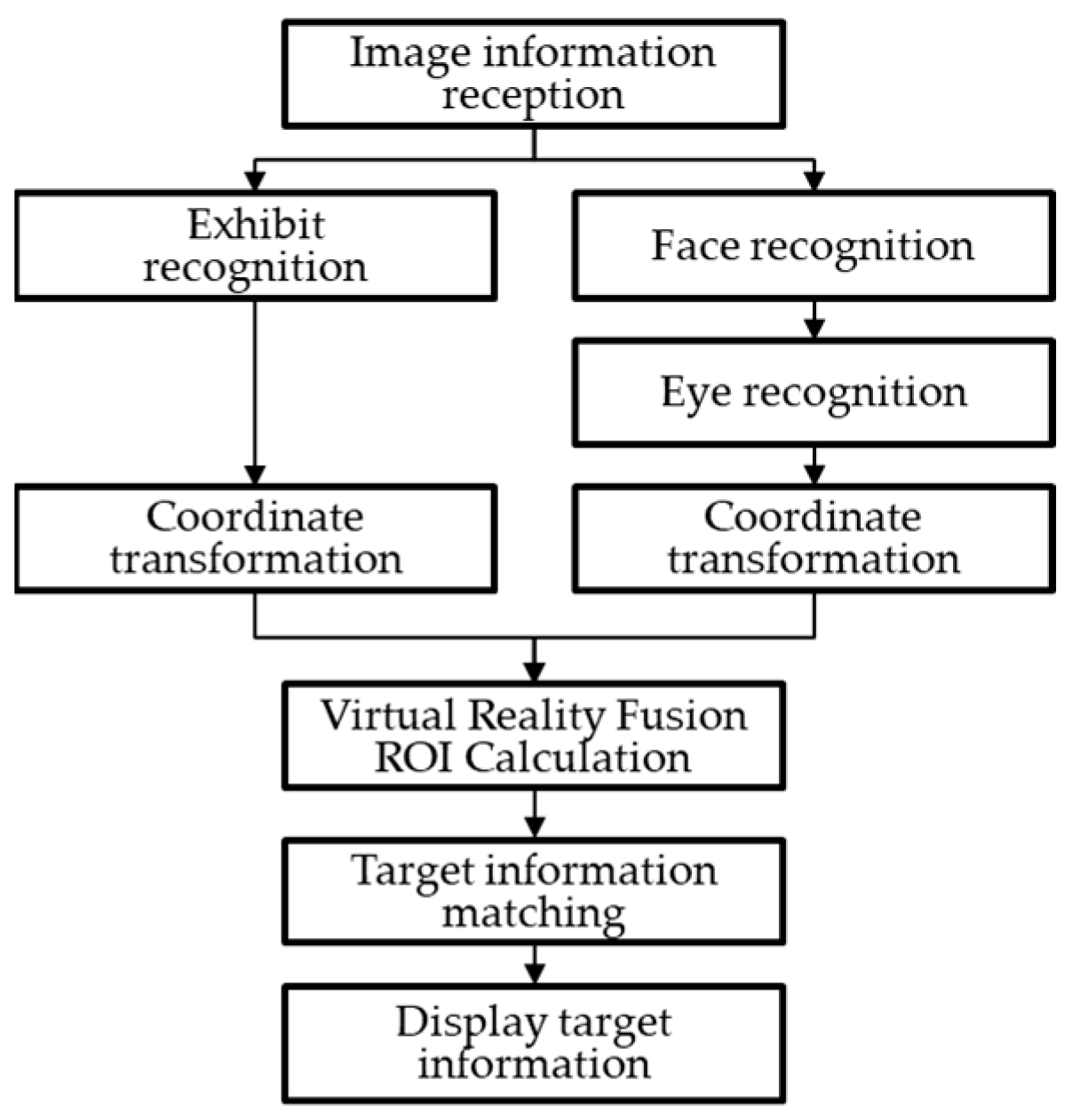
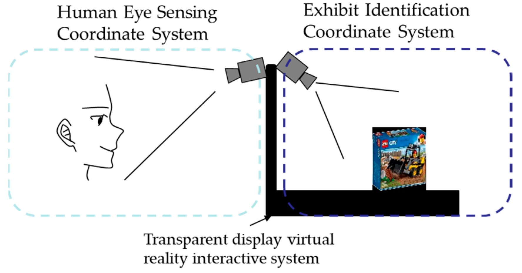
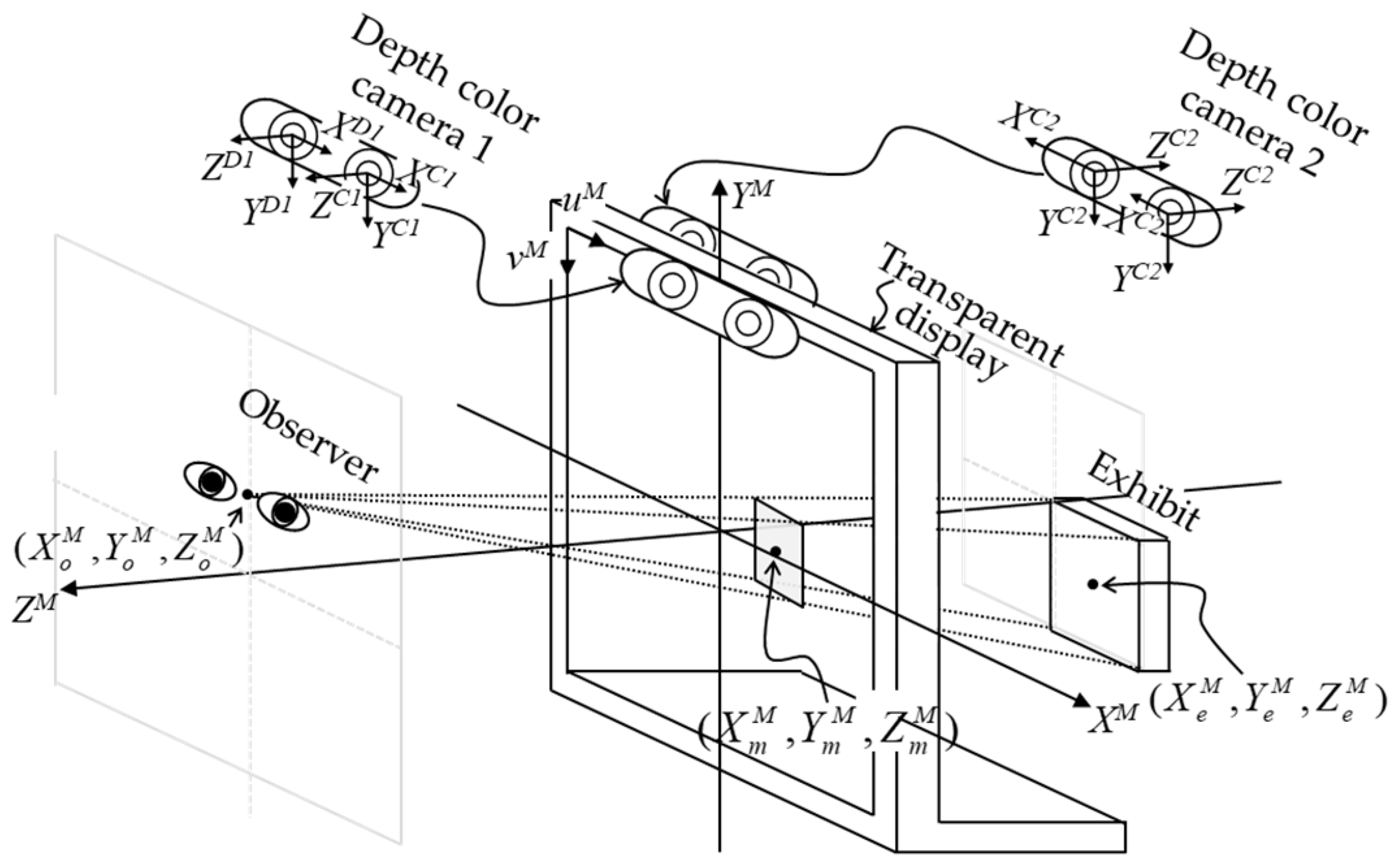
2. Information Fusion Method
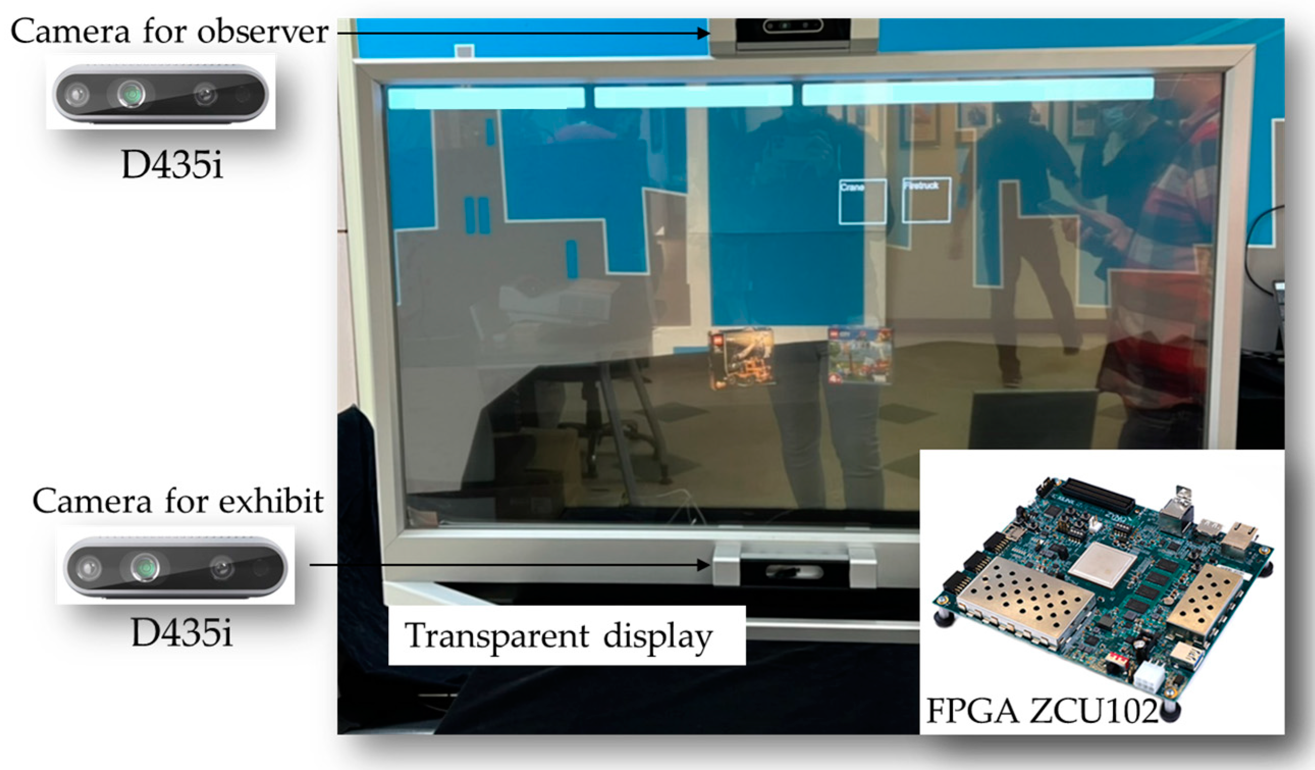
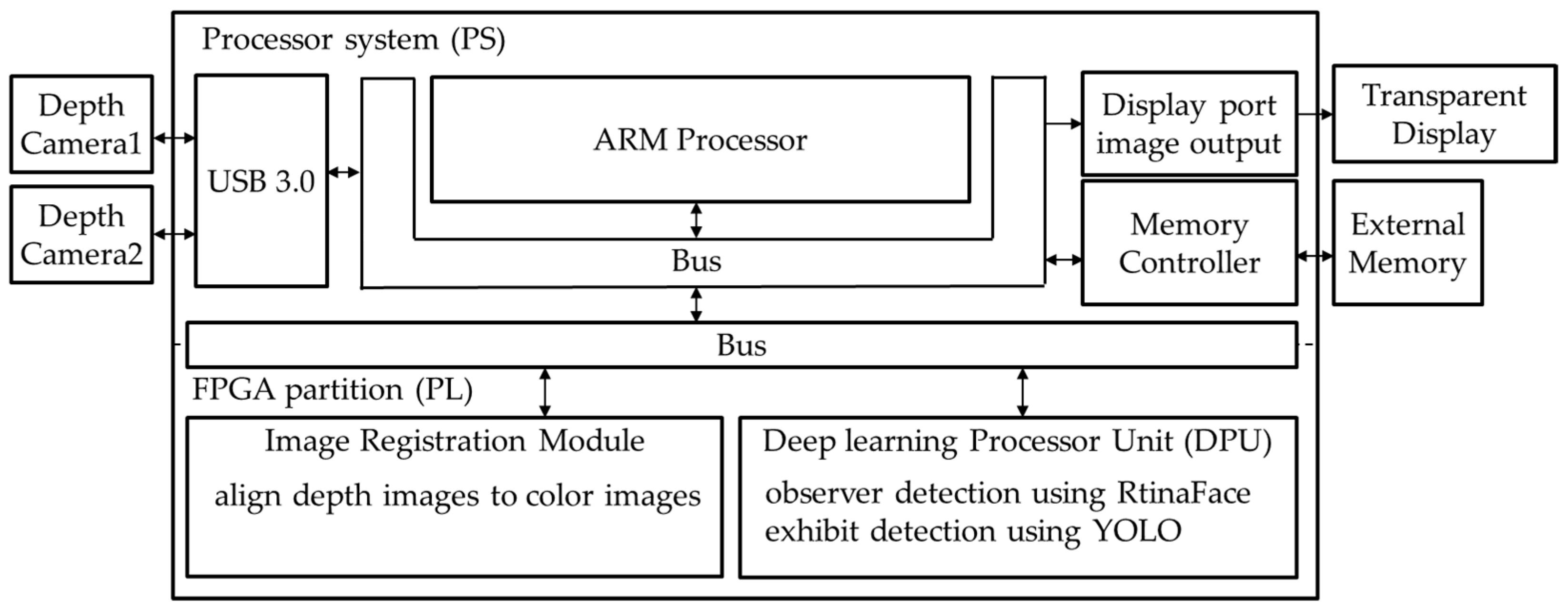
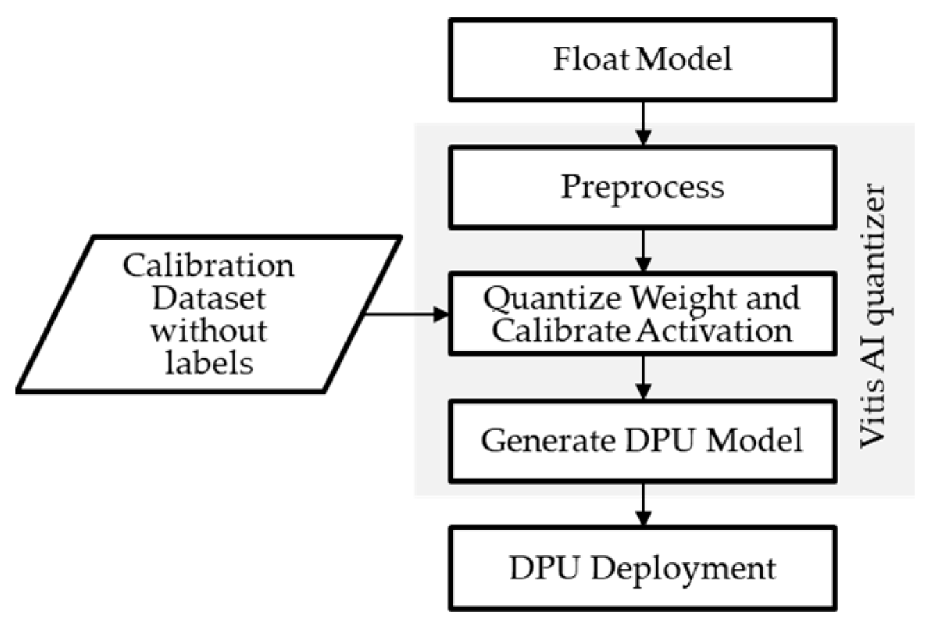
The information fusion system can generate an image in the line of sight of an observer that sees the image overlapped on their exhibit of interest. The side view of the information fusion system is shown in Figure 2. The system detects the positions of the observer and exhibit relative to that of the transparent display. Thus, the system employs two depth-color cameras to capture the color and depth images of the observer and exhibit. The system receives these images and feeds them into neural network models, which locate the observer and exhibit in the color images. The identified positions of the observer and exhibit in the color images are then used to determine their positions in the depth image corresponding to the color images. Thus, the positions of the observer and exhibit in the real world can be derived by mapping their positions in the image coordinates from the real world coordinates. Subsequently, the system calculates the displayed position and size of the fusion information according to the relative positions of the observer and exhibit. Finally, the system displays the fusion information on a transparent display to provide additional details for the exhibit. The workflow of the information fusion system is illustrated in Figure 3.
The system performs two essential processes: recognition and position acquisition of the fusion information. In the position-acquisition process, the system performs image registration between the depth and color images. The depth-to-color image coordinate maps are derived using Equations (1)–(3), shown below:
[ X D Y D Z D ] = d [ f x D 0 p x D 0 f y D p x D 0 0 1 ] 1 [ u D v D 1 ]
[ X C Y C Z C ] = [ r 11 D C r 12 D C r 13 D C t 1 D C r 21 D C r 22 D C r 23 DC t 2 D C r 31 D C r 32 D C r 33 DC t 3 D C 0 0 0 1 ] [ X D Y D Z D 1 ]
Z C [ u C v C 1 ] = [ f x C 0 p x C 0 f y C p y C 0 0 1 ] [ X C Y C Z C ]
Equation (1) is the transformation from the two-dimensional depth image coordinate (uD, vD) to the three-dimensional depth camera coordinate (XD, YD, ZD). fxD and fyD are the focal lengths of the depth camera; pxD and pyD are the central positions of the depth image; d is the depth data of the depth image. Equation (2) is the transformation from the depth camera coordinate to the three-dimensional color camera coordinate (XC, YC, ZC). r11DC to r33DC are the rotation parameters, and t1DC to t3DC are the translation parameters. Equation (3) is the transformation from the color camera coordinate to the two-dimensional color image coordinate (uC,vC).
After detecting the observer or exhibit in the color image, the position of observer or exhibit in the three-dimensional color camera coordinate can be derived from the inverse transformation of Equation (3). Next, the positions are mapped to the three-dimensional transparent display coordinate (XM, YM, ZM) according to Equation (4), expressed below:
[ X M Y M Z M ] = [ r 11 C M r 12 C M r 13 C M t 1 C M r 21 C M r 22 C M r 23 C M t 2 C M r 31 C M r 32 C M r 33 C M t 3 C M 0 0 0 1 ] [ X C Y C Z C 1 ]
Here, r11CM to r33CM are the rotation parameters, and t1CM to t3CM are the translation parameters.
The positions of the observer and exhibit in the transparent display coordinate are (XoM, YoM, ZoM) and (XeM, YeM, ZeM), respectively. Equation (5) is used to calculate the position of the fusion information in the transparent display coordinate system. The coordinate (XmM, YmM, ZmM) represents the position of the fusion information in Figure 4.
[ X m M Y m M ] = Z e M Z e M Z o M [ X o M Y o M ] + Z o M Z e M Z o M [ X e M Y e M ]
Finally, the position and size coordinates of the transparent display are mapped to the transparent image coordinate for display according to Equation (6).
[ u M v M ] = [ s x 0 p x 0 s y p y 0 0 1 ] [ X M Y M 1 ]

3. Implementation

The information fusion system mainly comprised a transparent display, two depth cameras, Realsense D435i, and a Xilinx Zynq UltraScale+ MPSoC ZCU102 development board. The depth camera provided depth and color images for object detection. The development board contained an ARM-based FPGA XCZU9EG chip with a quad-core Arm® Cortex®-A53 (PS), dual-core Cortex-R5F real-time processors, Mali™-400 MP2 graphics processing unit (MGPU), and a PL. The PS side received image data and sent images to the PL. Image registration between the color and depth images was performed on the PL instead of on the PS, because the image registration was faster on the PL than on the PS. The PL contained a deep learning processor unit (DPU) that executed the exhibit and observer identification. The image registration and detection results were fed back to the PS. Next, the PS calculated the size and position of the information displayed on the transparent display according to the coordinates and depth values of the observer’s eyes and objects. The MGPU received the display information from the PS and updated the information to the transparent display. The computation architecture of the system is shown in Figure 5.
The PS performed multi-thread tasks using a total of four threads, including DecodeThread, DpuThread, SortingThread, and GuiThread. DecodeThread received the color and depth images and sent them to the PL for image registration. Then, DecodeThread received the image registration results and pushed the color images into a queue. DpuThread popped the images in the queue to the DPU for detecting the observer and exhibit and received the detection results, including the coordinates, sizes, and labels. SortingThread sorted the images in the queue according to the frame indices. GpuThread displayed the images at a specific position on the transparent display.
The information fusion system employed the RetinaFace and YOLO models to detect the face of the observer and exhibit, respectively. The RetinaFace model was pretrained and supported by the VITIS AI, which could rapidly apply the RetinaFace model on the DPU. The YOLO model for detecting LEGOs was self-trained and converted into a DPU-executable xmodel format; the conversion flow is shown in Figure 6. The parameters of the trained YOLO model were modified, as shown in Table 1, to run it on the DPU. The size of the image sent as an input to the DPU was 512 × 512 pixels. Moreover, because the DPU did not support the mish activation function, the leaky rectified linear unit activation function was used. The max-pooling sizes were reduced, because the maximum maxpool size of the DPU was limited to eight. Furthermore, the computing number format of the model was converted from floating-point to integer by the VITIS AI quantizer to increase the computation speed.
The image registration function was programmed using C++, and the VITIS™ High-Level Synthesis tool was utilized to synthesize the function into the registration level (RTL) module for the PL implementation. The code is displayed in Table A1. The input image size is 640 × 480 pixels, and the input parameter includes the intrinsic and intrinsic parameters of the color and depth cameras. Lines 10 to 19 in Table A1 describe the coordinate transformation from the depth camera coordinate to the color camera coordinate. Lines 20 and 21 in Table A1 describe the depth data alignment in the color camera coordinates.

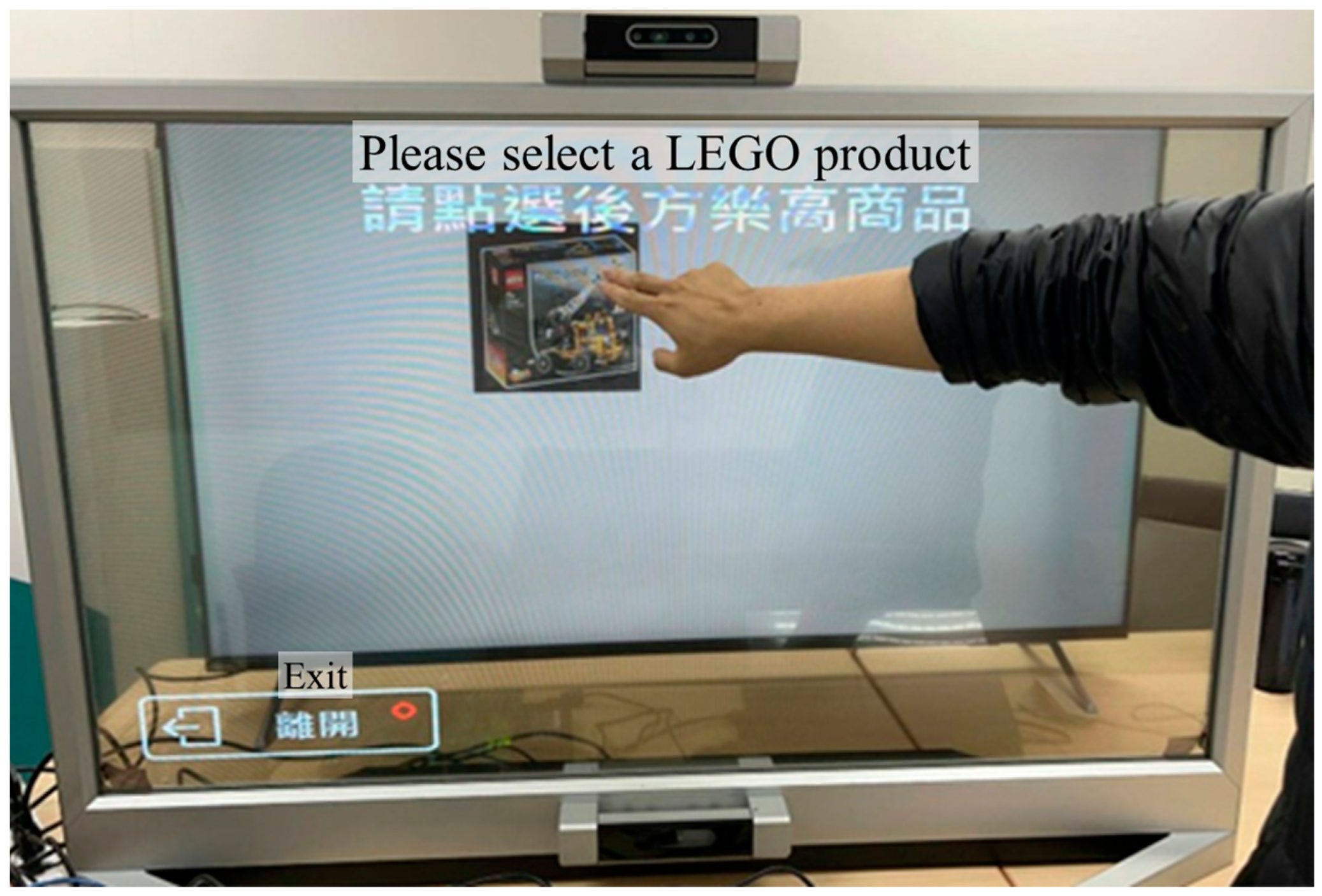
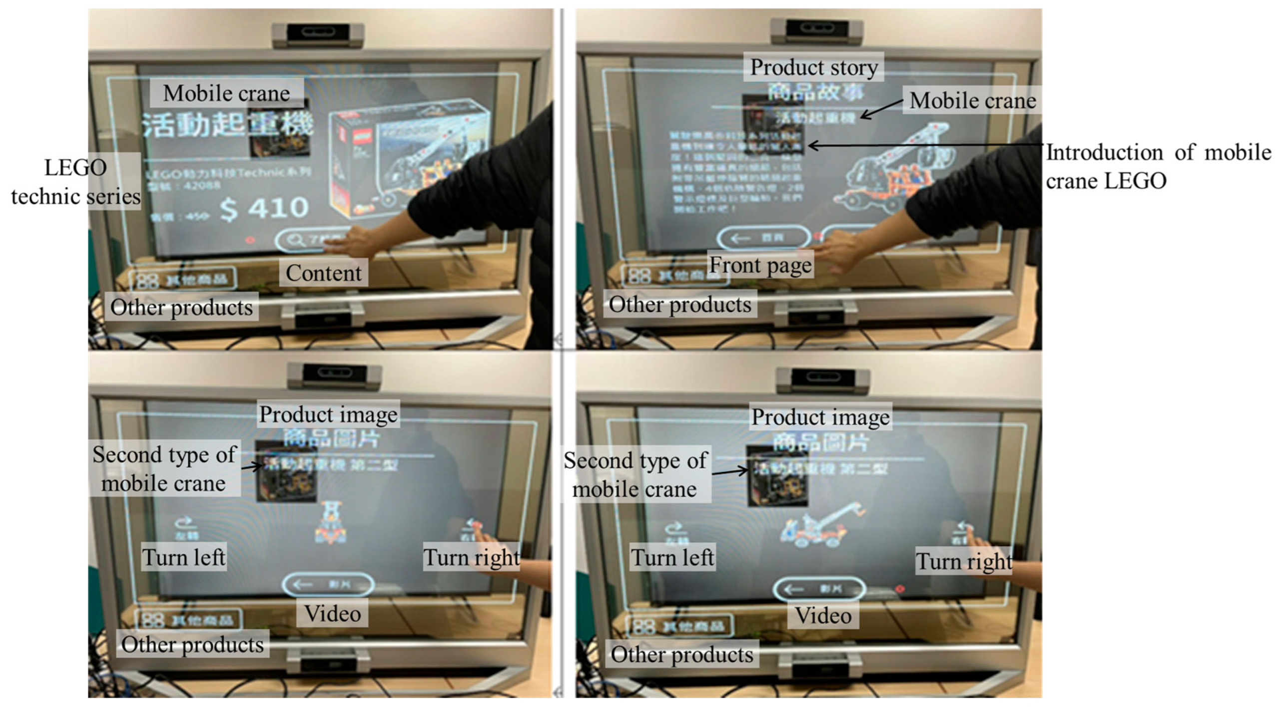
4. Experimental Setup and Results

The total utilization of XCZU9EG is described in Table 2. The first row of each module presents the total number of units used by this module, and the second row shows the resources used by the module as a percentage of the total resources. The image registration model used 4.46% of the look-up-table (LUT), 3.64% of the register (REG), and 2.94% of the digital signal-processing (DSP) unit in XCZU9EG. Two DPU units were used for the RetinaFace and YOLO models. DPUCZDX8G_1 used 19.69%, 18.86%, 30.82%, 27.38% of the LUT, REG, Block RAM (BRAM), and DSP, respectively. In contrast, DPUCZDX8G_2 used 19.78%, 18.90%, 30.82%, and 27.38% of the LUT, REG, BRAM, and DSP, respectively. Thus, the two DPU units used 39.47%, 37.76%, 61.64%, and 54.76% of the LUT, REG, BRAM, and DSP, respectively. Evidently, most resources were used for the DPU processing. The total utilization of the information fusion accounted for 50–60% of the entirety of the resources in XCZU9EG.
A Linux system on the ARM side executes the application program to execute image reading, detecting object frame selection, and name marking, as well as to obtain the image output. The interface includes functions to open advertisement video, select the target object to watch, and jump to the relevant introduction interface after clicking the display. The position of the human eye and exhibit are recognized using the front and rear depth cameras, respectively. The position of the object on the screen seen by the eyes is calculated using the above-mentioned relative position formula. The directional touch function realized in the ARM-based FPGA platform is shown in Figure 7. After clicking the target, the corresponding introduction interface is displayed, as shown in Figure 8.

5. Conclusions and Discussion

Lyu et al. [18] implemented a YOLOv4 model on the FPGA platform to identify citrus flowers; the computing speed of this model was approximately 33.3 ms, and the power consumption of the FPGA was 20 W. Pérez et al. [19] used an FPGA with a CNN model for image classification and achieved a speed of 24.6 frames per second. Previous studies indicate that the FPGA can accelerate AI computations. In this study, we successfully used an ARM-based FPGA to implement a fusion information system with a transparent display. The ARM-based FPGA accelerated the information fusion processes, including image registration, face recognition, and object recognition. The PL and PS executed image registration in approximately 3 ms and 1.1 s, respectively, indicating that the image registration speed of the PL was higher than that of the PS. Consequently, the PL side used approximately 46.2% of the total resources to fuse the information. The ARM-based FPGA and the computer with GPU RTX2060 performed information fusion in 25 ms and 47 ms, indicating that the information fusion speed of the ARM-based FPGA was 1.8 times more than that of the computer with GPU RTX2060.

Author Contributions

Conceptualization, Y.-H.T. and M.O.-Y.; methodology, M.-H.H.; software, M.-H.H.; validation, M.-H.H. and T.-Y.Y.; resources, Y.-H.T. and M.O.-Y.; data curation, M.-H.H.; writing—original draft preparation, T.-Y.Y.; writing—review and editing, Y.-H.T., Y.-J.Y. and M.O.-Y.; visualization, T.-Y.Y.; supervision, Y.-H.T., Y.-J.Y. and M.O.-Y.; project administration, Y.-H.T., Y.-J.Y. and M.O.-Y.; funding acquisition, Y.-H.T. and M.O.-Y.; All authors have read and agreed to the published version of the manuscript.

Funding

This research received no external funding.

Institutional Review Board Statement

Not applicable.

Informed Consent Statement

Not applicable.

Data Availability Statement

Data sharing is not applicable.

Acknowledgments

This paper was particularly supported by grant MOEA 112-EC-17-A-24-171 from the Ministry of Economic Affairs, Taiwan, the Industrial Technology Research Institute, Taiwan, and National Yang Ming Chiao Tung University, Taiwan.

Conflicts of Interest

The authors declare no conflict of interest.

Appendix A

Table A1. C++ code of image registration for the High-level RTL synthesis.
1void align_depth_to_color_2(float intrinsics_color[4], float intrinsics_depth[4], float extrinsics_depth_to_color[12], float depth_scale ,unsigned short int depth[307200], float depth_of_color[640*480]) {
2 float pd_uv[2];
3 float Pd_uv[3];
4 float Pc_uv[3];
5 unsigned short int pc_uv[2];
6 for(int i = 0; i < 480; i++) {
7 //#pragma HLS pipeline II = 1
8  for(int j = 0; j < 640; j++) {
9  //#pragma HLS pipeline II = 1
10   pd_uv[0] = j;
11   pd_uv[1] = i;
12   Pd_uv[0] = (pd_uv[0]-intrinsics_depth[2]) * depth[i*640+j]*depth_scale/intrinsics_depth[0];
13   Pd_uv[1] = (pd_uv[1]-intrinsics_depth[3]) * depth[i*640+j]*depth_scale/intrinsics_depth[1];
14   Pd_uv[2] = depth[i*640+j]*depth_scale;
15   Pc_uv[0] = extrinsics_depth_to_color[0] * Pd_uv[0] + extrinsics_depth_to_color[1] * Pd_uv[1] + extrinsics_depth_to_color[2] * Pd_uv[2] + extrinsics_depth_to_color[3];
16   Pc_uv[1] = extrinsics_depth_to_color[4] * Pd_uv[0] + extrinsics_depth_to_color[5] * Pd_uv[1] + extrinsics_depth_to_color[6] * Pd_uv[2] + extrinsics_depth_to_color[7];
17   Pc_uv[2] = extrinsics_depth_to_color[8] * Pd_uv[0] + extrinsics_depth_to_color[9] * Pd_uv[1] + extrinsics_depth_to_color[10] * Pd_uv[2] + extrinsics_depth_to_color[11];
18   pc_uv[0] = (unsigned short int)((intrinsics_color[0] * Pc_uv[0]/Pc_uv[2] + intrinsics_color[2]));
19   pc_uv[1] = (unsigned short int)((intrinsics_color[1] * Pc_uv[1]/Pc_uv[2] + intrinsics_color[3]));
20   if(pc_uv[0] < 640 && pc_uv[0] ≥ 0 && pc_uv[1] < 480 && pc_uv[0] ≥ 0 )
21    depth_of_color[pc_uv[1] * 640 + pc_uv[0]] = Pd_uv[2];
22   }
23  }
24 }

References

  1. Santi, G.M.; Ceruti, A.; Liverani, A.; Osti, F. Augmented Reality in Industry 4.0 and Future Innovation Programs. Technologies 2021, 9, 33. [Google Scholar] [CrossRef]
  2. Carbone, M.; Cutolo, F.; Condino, S.; Cercenelli, L.; D’Amato, R.; Badiali, G.; Ferrari, V. Architecture of a Hybrid Video/Optical See-through Head-Mounted Display-Based Augmented Reality Surgical Navigation Platform. Information 2022, 13, 81. [Google Scholar] [CrossRef]
  3. Lex, J.R.; Koucheki, R.; Toor, J.; Backstein, D.J. Clinical applications of augmented reality in orthopaedic surgery: A comprehensive narrative review. Int. Orthop. 2023, 47, 375–391. [Google Scholar] [CrossRef] [PubMed]
  4. Titov, W.; Keller, C.; Schlegel, T. Augmented Reality Passenger Information on Mobile Public Displays—An Iterative Evaluation Approach. In HCI in Mobility, Transport, and Automotive Systems; Krömker, H., Ed.; HCII 2021; Lecture Notes in Computer Science; Springer: Berlin/Heidelberg, Germany, 2021; p. 12791. [Google Scholar] [CrossRef]
  5. Liu, Y.T.; Liao, K.Y.; Lin, C.L.; Li, Y.L. 66-2: Invited Paper: PixeLED display for transparent applications. Proceeding SID Symp. Dig. Tech. Pap. 2018, 49, 874–875. [Google Scholar] [CrossRef]
  6. Mohr, P.; Mori, S.; Langlotz, T.; Thomas, B.H.; Schmalstieg, D.; Kalkofen, D. Mixed reality light fields for interactive remote assistance. In Proceedings of the 2020 CHI Conference on Human Factors in Computing Systems, Honolulu, HI, USA, 25–30 April 2020; pp. 1–12. [Google Scholar]
  7. Shawahna, A.; Sait, S.M.; El-Maleh, A. FPGA-based accelerators of deep learning networks for learning and classification: A review. IEEE Access 2018, 7, 7823–7859. [Google Scholar] [CrossRef]
  8. Rizzatti, L. A Breakthrough in FPGA-Based Deep Learning Inference. Available online: https://www.eeweb.com/a-breakthrough-in-fpga-based-deep-learning-inference/ (accessed on 18 July 2023).
  9. Farabet, C.; Poulet, C.; Han, J.Y.; LeCun, Y. Cnp: An FPGA-based processor for convolutional networks. In Field Programmable Logic and Applications; IEEE: Prague, Czech Republic, 2009; pp. 32–37. [Google Scholar] [CrossRef]
  10. Denton, E.L.; Bruna, W.J.; LeCun, Y.; Fergus, R. Exploiting linear structure within convolutional networks for efficient evaluation. In Proceedings of the Advances in Neural Information Processing Systems, Montreal, Canada, 8–11 December 2014; pp. 1269–1277. [Google Scholar]
  11. LeCun, Y.J.; Denker, S.; Solla, S.A. Optimal brain damage. In Proceedings of the Advances in Neural Information Processing Systems, Denver, CO, USA, 26–29 November 1989; pp. 598–605. [Google Scholar]
  12. Hanson, S.J.; Pratt, L.Y. Comparing biases for minimal network construction with back-propagation. In Proceedings of the Advances in Neural Information Processing Systems, Denver, CO, USA, 27–30 November 1989; pp. 177–185. [Google Scholar]
  13. Hassibi, B.; Stork, D.G. Second order derivatives for network pruning: Optimal brain surgeon. In Proceedings of the Advances in Neural Information Processing Systems, San Francisco, CA, USA, 30 November–3 December 1992; pp. 164–171. [Google Scholar]
  14. Han, S.; Mao, H.; Dally, W.J. Deep compression: Compressing deep neural networks with pruning, trained quantization and huffman coding. arXiv 2015, arXiv:1510.00149. [Google Scholar]
  15. Gupta, S.; Agrawal, A.; Gopalakrishnan, K.; Narayanan, P. Deep learning with limited numerical precision. In Proceedings of the International Conference on Machine Learning (PMLR 2015), Lille, France, 6–11 July 2015; pp. 1737–1746. [Google Scholar]
  16. Guo, K.; Sui, L.; Qiu, J.; Yu, J.; Wang, J.; Yao, S.; Han, S.; Wang, Y.; Yang, H. Angel-eye: A complete design flow for mapping CNN onto embedded FPGA. IEEE Trans. Comput. Aided Des. Integr. Circuits Syst. 2018, 37, 35–47. [Google Scholar] [CrossRef]
  17. Migacz, S. 8-Bit Inference with TensorRT. Available online: https://on-demand.gputechconf.com/gtc/2017/presentation/s7310-8-bit-inference-with-tensorrt.pdf (accessed on 18 July 2023).
  18. Lyu, S.; Zhao, Y.; Li, R.; Li, Z.; Fan, R.; Li, Q. Embedded Sensing System for Recognizing Citrus Flowers Using Cascaded Fusion YOLOv4-CF + FPGA. Sensors 2022, 22, 1255. [Google Scholar] [CrossRef] [PubMed]
  19. Pérez, I.; Figueroa, M. A Heterogeneous Hardware Accelerator for Image Classification in Embedded Systems. Sensors 2021, 21, 2637. [Google Scholar] [CrossRef] [PubMed]
Figure 1. Devices used in the information fusion system.
Applsci 13 08497 g001
Figure 2. Side view of the information fusion system.
Applsci 13 08497 g002
Figure 3. Working flow chart of the information fusion system.
Applsci 13 08497 g003
Figure 4. Schematic and coordinate definition of the information fusion system.
Applsci 13 08497 g004
Figure 5. Computation system block diagram.
Applsci 13 08497 g005
Figure 6. Conversion flow for applying a self-trained model to the DPU in Xilinx Zynq UltraScale+ MPSoC Chip.
Applsci 13 08497 g006
Figure 7. Touch the screen to select the exhibit behind the transparent display.
Applsci 13 08497 g007
Figure 8. Transparent display shows the introduction overlapped on the exhibit in the field-of-view of the observer.
Applsci 13 08497 g008
Table 1. Modified parameters of the self-trained YOLO model for the Xilinx DPU.
ParametersOriginFor Xilinx DPU
Input image weight608512
Input image height608512
Activation functionmishleaky
Max-pooling size 196
Max-pooling size 2138
Table 2. Utilization of XCZU9EG resources. The first row of each module presents the total number of units used by this module, and the second row shows the resources used by the module as a percentage of the total resources.
Module NameLUTLUTAsMemREGBRAMDSP
DPUCZDX8G_151,082568097,940257690
(19.69%)(3.98%)(18.86%)(30.82%)(27.38%)
DPUCZDX8G_251,308568098,128257690
(19.78%)(3.98%)(18.90%)(30.82%)(27.38%)
Image registration11,56898118,9231574
(4.46%)(0.69%)(3.64%)(1.80%)(2.94%)
sfm_xrt_top96385408142414
(3.71%)(0.38%)(1.57%)(0.48%)(0.56%)
Total Utilization138,21914,139251,9936121468
(50.00%)(10.00%)(46.00%)(67.00%)(58.00%)
Disclaimer/Publisher’s Note: The statements, opinions and data contained in all publications are solely those of the individual author(s) and contributor(s) and not of MDPI and/or the editor(s). MDPI and/or the editor(s) disclaim responsibility for any injury to people or property resulting from any ideas, methods, instructions or products referred to in the content.

