Abstract
Floating, pouring, prefabrication, and temporary storage of the immersed tunnel element require mooring inside a harbor or a dock. However, the dynamics of a moored tunnel element in such semi-open waters are rarely studied, and some mechanisms are not well understood yet. Clarifying the dynamic response characteristics of a tunnel element moored inside a harbor is useful for the evaluation and design of the mooring system. In this paper, by carrying out physical model tests, the law of wave development in the harbor was investigated, and the motion response of the tunnel element and cable force of the mooring system were also measured. Dynamic response characteristics under different environmental factors, the influence of tunnel element load conditions, and the mutual interference of multiple elements moored simultaneously were analyzed. The results show that dynamic response characteristics under wind are significantly different from those under waves. Under no-load or half-load conditions, which correspond to greater freeboard-to-draft ratios, the dynamic responses of the tunnel element are more unfavorable than those under heavy-load or full-load conditions. The scheme of simultaneous mooring of multiple elements inside a harbor is feasible if there is appropriate spacing between them.
1. Introduction
The immersed tunnel is widely used around the world to cross rivers and seas owing to its unique advantages in economy and technology. Since the concept was proposed in the early 19th century and the first one was built in the early 20th century, nearly 150 immersed tunnels for transportation have been built around the world. The construction of an immersed tunnel includes some key processes such as trench excavation, tunnel element prefabrication, transportation and immersion, treatment of joints, and foundation, among which several processes involve mooring, such as in the stages of floating pouring, prefabrication, storage, and outfitting before transportation and immersion. It is of great significance to study the dynamic response of the mooring tunnel element to clarify the dynamic response mechanisms, better design the mooring systems, and scientifically evaluate the mooring stability.
At present, much research has been carried out on the dynamic response of moored immersed tunnel elements by means of theoretical analysis, model tests, and numerical simulations. Xiao [1] carried out experimental observations of moored tunnel elements under the combined action of waves and currents in open water. Chen [2], Lv [3,4], Shen [5], Su [6], and Wu [7], based on the Hong Kong-Zhuhai-Macao Bridge immersed tunnel project, carried out a series of hydrodynamic experiments on a tunnel element in transportation and immersion stages and obtained the drift force, the motion response of an element during the immersion stage, and the cable tension under the specific waves, current, and wind environments. Based on the potential flow theory, Yang [8,9] calculated the motion response of a tunnel element under different anchoring patterns by numerical methods and analyzed the influences of wave period, height, and incident direction on the motion. Shao [10] studied the hydrostatic attenuation characteristics of the element-barge combined system and the forces on the mooring lines under different mooring schemes, different flow rates, and different wave conditions by means of physical model tests. Wu [11] used the theory of three-dimensional potential flow to study the nonlinear wave load in the floating process of large tunnel elements under the action of irregular waves and analyzed the influences of water depths, wave heights, and periods on the wave force and the motion. Song [12] studied the motion response of a moored tunnel element and mooring cable tension in the immersion stage under the action of long-period waves through physical model tests. The results showed that the heave and roll of a tunnel element under long-period waves were significantly affected by the wave period. When the wave period was smaller than the roll period, the average drift force had little effect on the net drift. Both waves and currents have important effects on mooring tension, and a better mooring scheme was obtained by comparing and analyzing different mooring schemes. Song [13,14] also studied the dynamic response of a tunnel element in the stages of standby and freeboard elimination by using physical model tests. Ning [15] analyzed the four kinds of anti-typhoon schemes for a tunnel element and recommended an optimal mooring scheme for closed water.
Most of the previous studies are aimed at the mooring of tunnel elements in open waters, corresponding to the immersion and standby stages, while for the mooring in semi-open waters, such as a mooring inside a harbor or a dock, corresponding to the prefabrication and temporary storage stages, there are few studies. It should be noted that the tunnel element moored in semi-open water is different from that in open water. The environmental conditions of the mooring in these two types of areas are quite different. Because of the shielding effect of the structures, the environmental conditions of a mooring inside the harbor will be weakened, which seems to be more favorable to the mooring stability. However, the moored tunnel element in the prefabrication stage experiences a continuous transformation from a no-load to a full-load with the progress of pouring, and the corresponding freeboard-to-draft ratio would change significantly, which is different from that in the immersion and standby stages. Moreover, it is necessary to face the difficulty that multiple elements may interfere with each other when they are moored simultaneously in the limited water space. In addition, the box-type immersed tunnel element is usually a long, wide, and shallow structure, different from ships. The dynamic response under the action of wind, waves, and a current environment also has its own unique characteristics. In short, it is extremely necessary and important to carry out corresponding research on the dynamic response characteristics of immersed tunnel elements inside the harbor.
This study is based on the Shenzhong-link immersed tunnel project. The immersed tunnel consists of 32 elements and a final joint, and some elements are prefabricated in Longxue Harbor, which is located at the Pearl River estuary and may be affected by strong waves from the open sea. A floating pouring scheme inside the harbor is one of the alternative prefabrication methods. After the prefabrication is completed, a tunnel element outfitting is carried out in the harbor, and then it is transported to the sinking site by towing. There is demand for mooring inside a harbor for element prefabrication and storage before transportation. In this paper, model tests focused on the dynamic response of a tunnel element moored inside the harbor are carried out, and the dynamic response characteristics under three different external force modes (wind, waves, and combined wind and wave) are investigated, as well as the influences of element load conditions on the mooring stability. In addition, the interaction of simultaneous mooring inside the harbor by multiple elements is also analyzed.
2. Experiments
2.1. Model Design
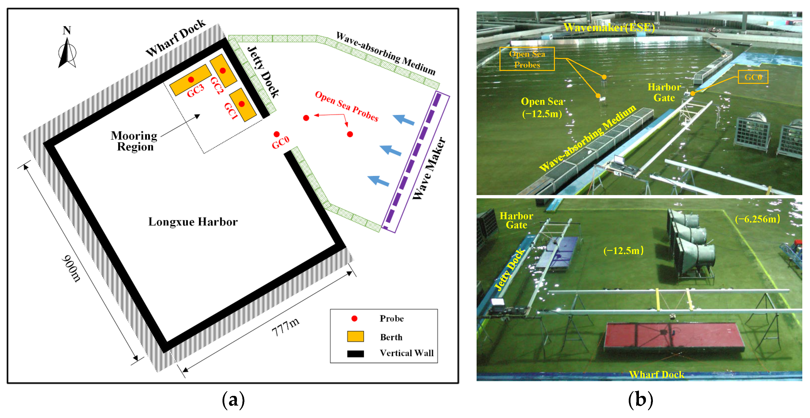
The model test was designed according to the gravity similarity criterion. The scale of the model was 1:50, and the scales of some important physical parameters are listed in Table 1. The experiment was carried out in a large hydrodynamic laboratory at the Tianjin Water Transport Engineering Research Institute. The test tank, 40 m long and 30 m wide, includes the whole Longxue Harbor and the nearby regions. The Longxue Harbor owns upright side walls, and the bottom elevations of the berths and adjacent working areas for the tunnel element are −12.5 m, while the bottom elevations of other parts are −6.256 m. A flat-type wavemaker is installed on the southeast and east sides of the test tank, and energy dissipation facilities filled with porous media are arranged along the offshore boundary. The layout of the model is shown in Figure 1. A series of probes were set to measure the wave height; probe GC0 is situated at the harbor gate, and probes GC1, GC2, and GC3 are situated at the center of element berths near the wharf and jetty, respectively.

Table 1.
The model scale of physical parameters in the experiment.

Figure 1.
Model layout. (a) Simplified plane view. (b) Real scenes.
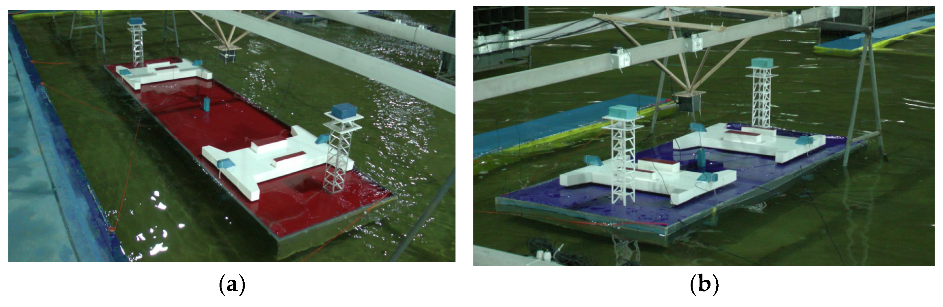
Two main types of tunnel elements were utilized in model tests the first type is a standard element, and the other type is a non-standard element. The heights of the two types of elements are both 10.6 m, but with different horizontal sizes. For the standard immersed element, its length is 165 m and its width is 46 m; for the non-standard immersed element E30, its length is 123.8 m, and its widths at the wider end and narrower ends are 53.50 m and 49.75 m, respectively; for the non-standard immersed element E32, its length is 123.8 m, and its widths at the wider end and narrower end are 55.46 m and 53.50 m, respectively. The shell of the immersed element model is made of high-strength PVC hardboard, the end sealing door is made of transparent acrylic board, and the three holes inside the immersed element are made of light wood-plastic plate, with a minimal counterweight space between the shell and the inner wood-plastic plate. The counterweight of the element model is achieved by the high-density lead sheet. There are two pontoons with a rod-bone plane. The geometric dimensions of their external outlines in the prototype are 40.62 m × 16 m × 3.0 m. The main body of the pontoon is a rectangular shell structure; the model material is wood; and waterproof paint is used for external protection. The pontoon uses a cement block as a counterweight to satisfy the similarity criterion on the center of gravity and mass distribution. The structure of the survey tower is complex, but the weight is very small compared with that of the immersed element. The model of the survey tower structure is made of light aluminum, and the small lead sheet is used for counterweighting. The key to making the pontoon model is to ensure that its wind area, total weight, and center of gravity position are similar. The immersed element model after outfitting is shown in Figure 2.

Figure 2.
Model of an immersed element after outfitting. (a) Standard immersed element. (b) Non-standard immersed element E32.
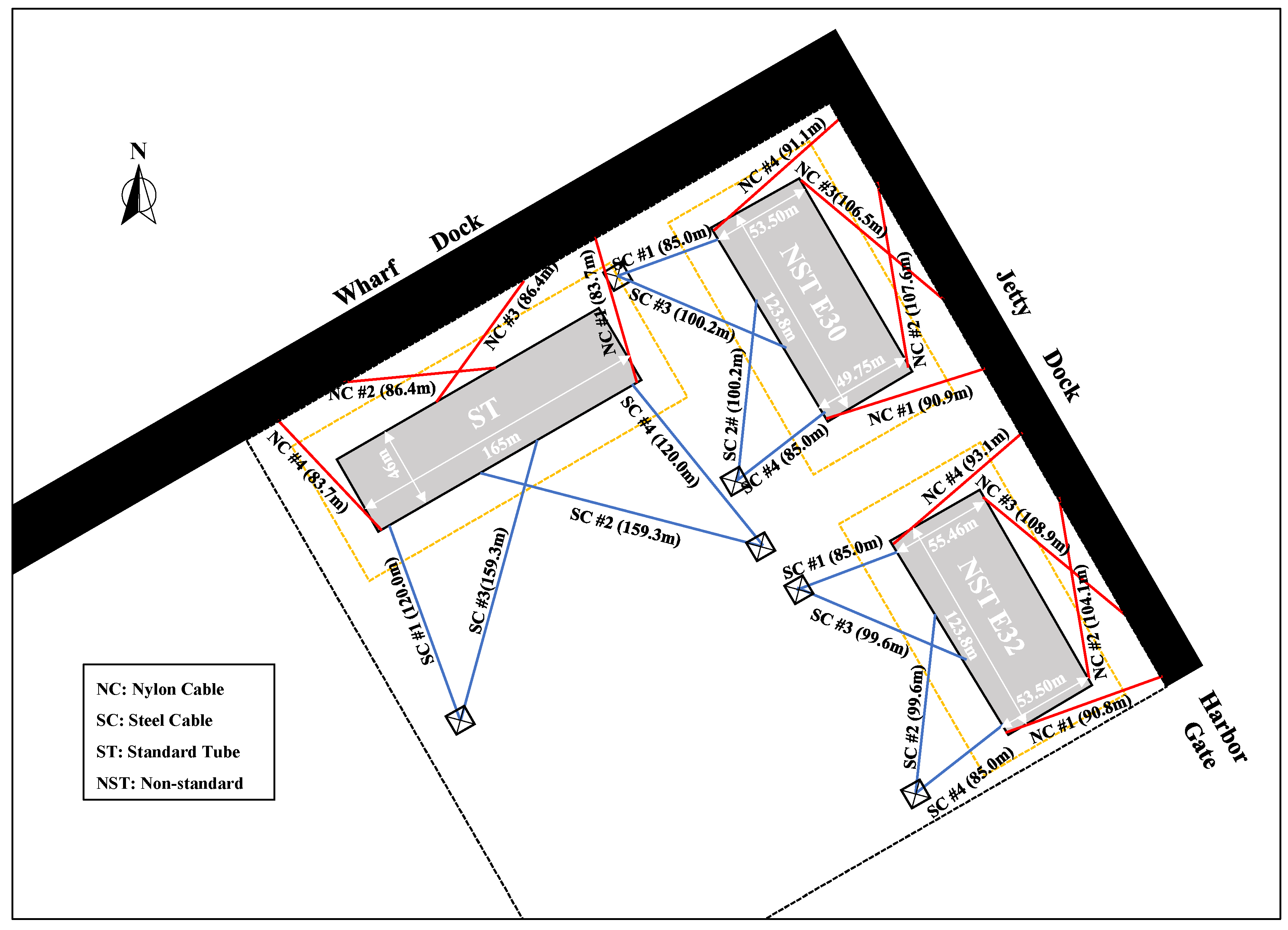
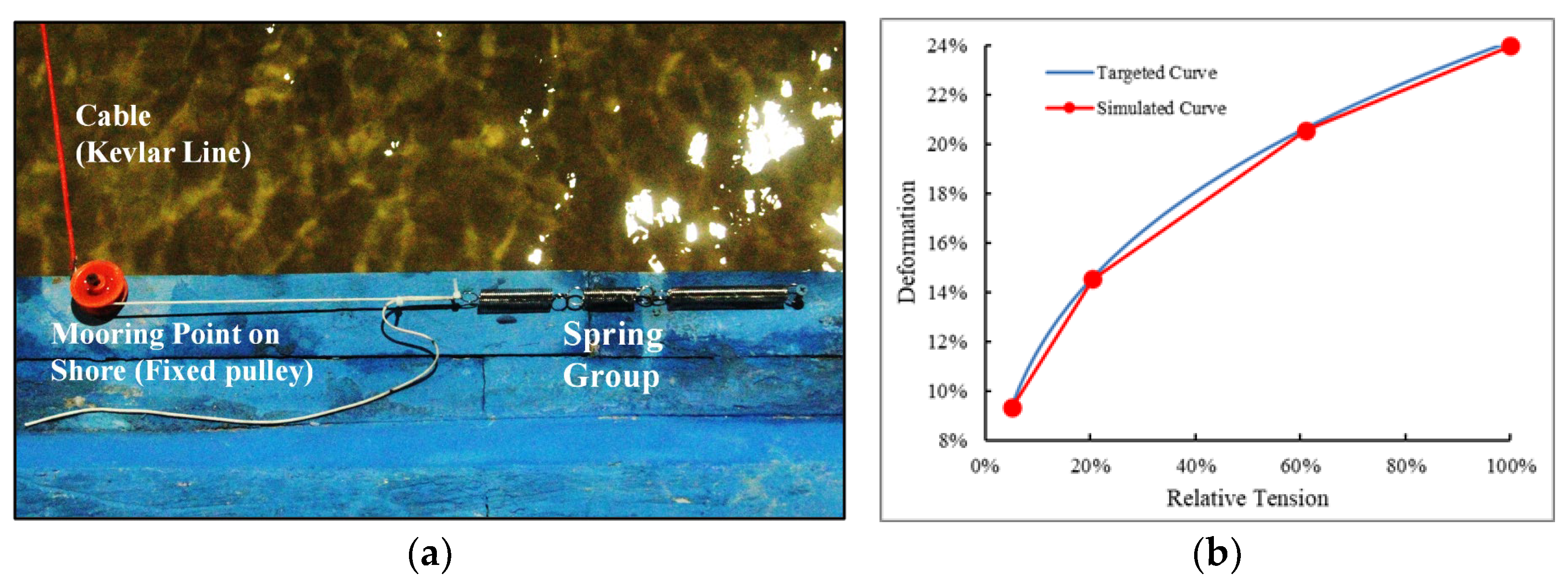
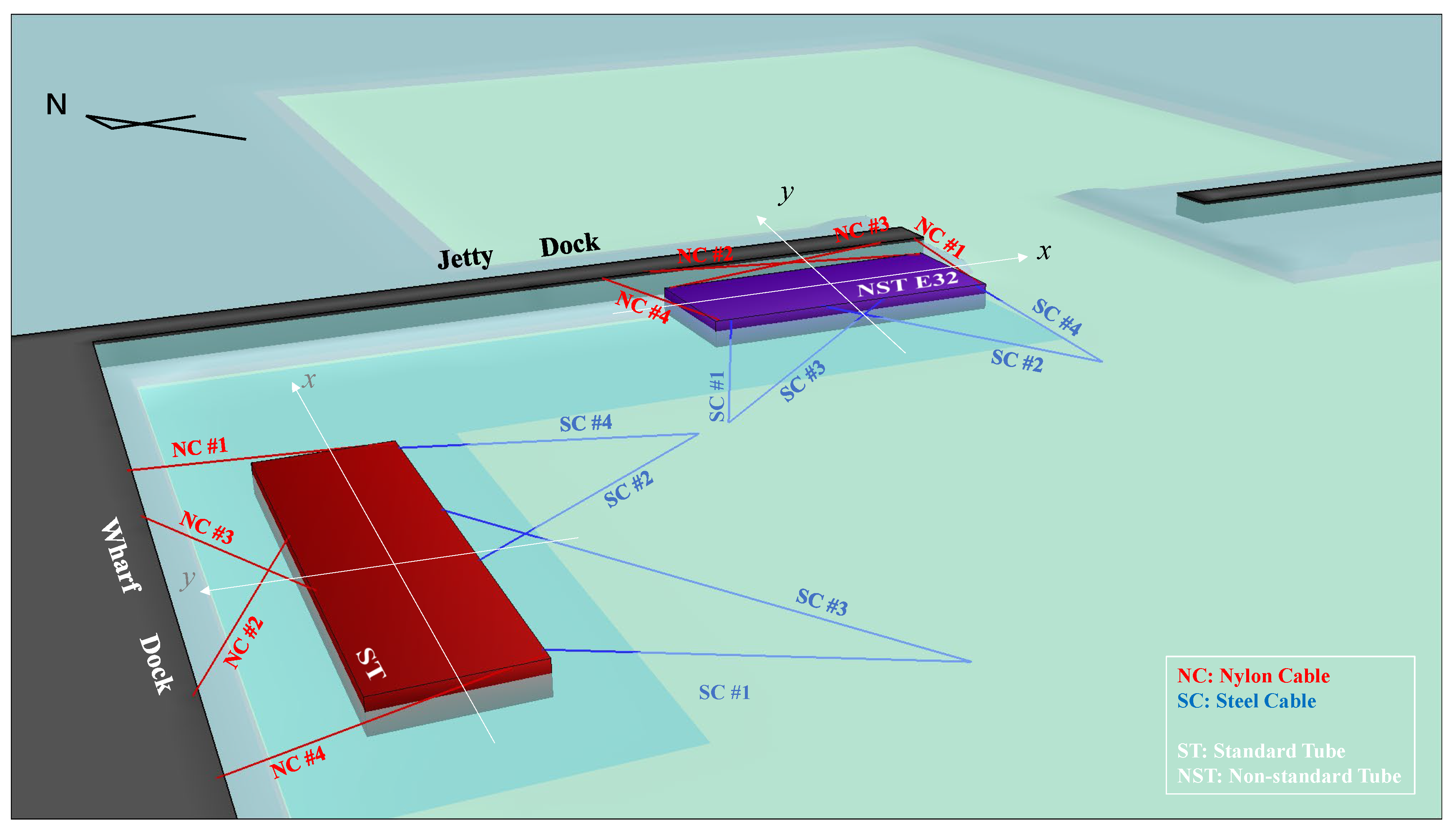
The immersed element is moored by 8 cables, among which the ones on the inshore side are nylon ones and the ones on the offshore side are steel ones. The plane layout and lengths of the mooring cables are shown in Figure 3. The cables situated in the middle of the immersed element are mainly used to restrain the longitudinal displacement, which can be called the longitudinal regulating cables (the corresponding number is 2# or 3#). While the cables situated at the ends of the immersed element are mainly used to restrain the transverse displacement, which can be called the transverse regulating cables (the corresponding number is 1# or 4#). The specifications and parameters of the cables made of different materials are shown in Table 2. The cable simulation satisfies geometric similarity and elastic similarity. The weight of the model cable is simulated in accordance with the weight per unit length of the prototype. The model cable consists of two parts. The first part is a spring or spring group that simulates cable tension deformation. The second part is wire with high strength and basically no tension deformation, such as Dupont wire, Kevlar wire, or Spark wire. For the deformation of nylon cable, three sets of springs are used for piecewise linear simulation of the nonlinear tension force and deformation curves of the actual cable (see Figure 4 for the targeted and simulated curves), while the steel cable is directly simulated by a set of springs.
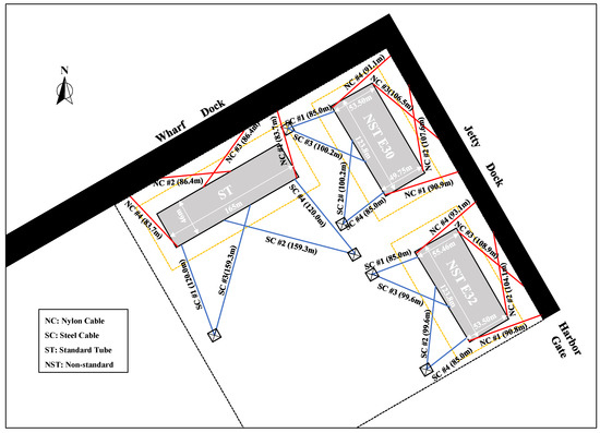
Figure 3.
Cable layout of each immersed element when mooring at the berth inside the harbor.
Table 2.
Specification of cables.
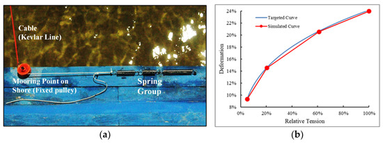
Figure 4.
Simulation of nylon cable. (a) Model of nylon cable. (b) Curve of relative deformation with relative tension.
2.2. Experimental Equipment and Measuring Instruments
The instruments used to measure cable force, motion, wave height, water level, wind speed, and other physical quantities in the test are shown in Table 3. The instrument for measuring the motion of the immersed element is the non-contact FASTRAK motion tracking system, which is based on the electromagnetic principle. The size of the receiving end is less than 1 cm, and the receiving end can be freely installed in any part of the floating or immersed structures. The maximum sampling frequency can reach 120 Hz. When the distance between the transmitting end and the receiving end is less than 60 cm, the instruments can obtain high measurement accuracy.
Table 3.
Measuring instruments and equipment.
The wave-making system adopted in the test is an irregular wavemaker with a movable and shakable plate (as shown in Figure 5a). The JONSWAP frequency spectrum is used in the experiments, and a value of 3.3 is adopted for the spectral peak factor. The given significant wave height and peak period are input into the computer for a spectrum simulation. After correction, the parameters of spectral density, peak frequency, spectral energy, and wave height near the peak frequency meet the test requirements.
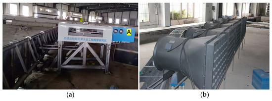
Figure 5.
Facilities for wave and wind simulations. (a) Wavemaker. (b) Fan array for wind. (In the subfigure a, the servo motor part is marked by letter A and the fixed support part is marked by letter B).
Simulation of the wind is realized by a fan array composed of 8 independent fans (as shown in Figure 5b). The fans can be arranged and combined arbitrarily to realize the targeted array type. The wind speed is controlled by adjusting the motor rotational frequency; the maximum wind speed at the fan outlet can reach 9 m/s, which meets the test requirements. In addition, the effective width of the wind field completely covers the length of the immersed element.
2.3. Experimental Conditions
The water depth of the berth in the harbor is 15.86 m. The wind speed of the fifty year return period is used for experimental wind, of which the average speeds in 10 min and 3 s at an elevation of 10 m above the water surface are 35.9 m/s and 47.4 m/s, respectively. For wind direction, both inshore wind and offshore wind are considered. As the current in the semi-opened harbor is weak, the effect of the current is ignored. The fifty year return period of the ESE wave was chosen as the test wave according to the results of the hydrological analysis. The significant wave height near the gate of the harbor is 2.00 m, and the average period is 5.5 s.
The layouts of mooring cables and mooring berths for each immersed element are shown in Figure 3. The immersed element refers to four different load conditions, which are no-load, half-load, heavy-load, and full-load, respectively. The weight, center of gravity, and draft of the immersed element under different load conditions are different. The detailed values of these parameters are shown in Table 4.
Table 4.
Immersed element’s parameters with different load conditions (prototype).
In this paper, the wave evolution tests and immersed element mooring tests inside the harbor are carried out. According to the number of moored immersed elements, the mooring test can be divided into two categories: the single element mooring test and the two element simultaneous mooring test. For the single element, mooring tests were carried out under different external force modes. Aiming at the simultaneous mooring of two elements, mooring tests for a relatively longer distance and a shorter distance under the action of waves were carried out. The specific test conditions for the mooring test are shown in Table 5.
Table 5.
Test conditions for the immersed element mooring test.
3. Results
This section is elaborated on in three parts. The first part is the wave evolution results inside the harbor, the second part is the dynamic response results of the single element under different environmental conditions, and the last part is the dynamic response results of two elements moored simultaneously under wave action.
3.1. Wave Evolution inside the Harbor
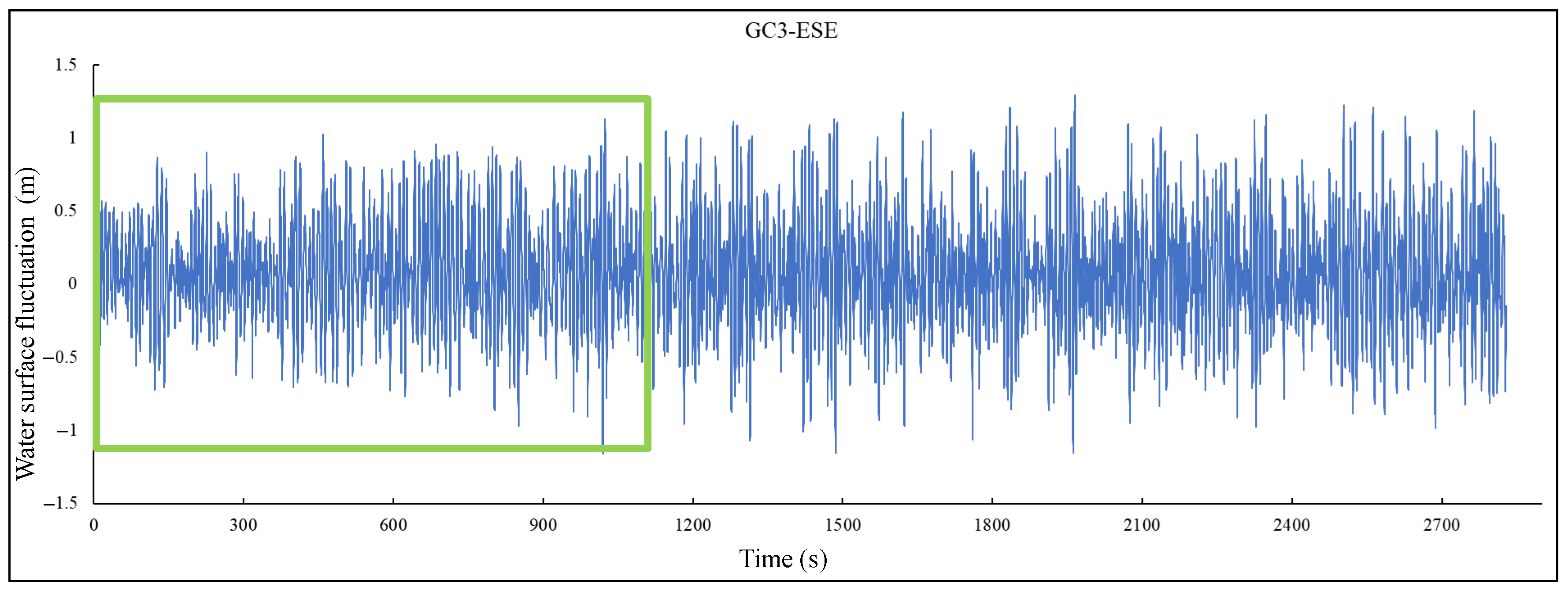
As waves from the open sea propagate into the harbor through the harbor gate, reflection occurs after encountering the upright side wall, and the reflected wave is superimposed on the incident wave. Wave energy aggregation may be formed, which could gradually increase the wave height at the berth. Additionally, the aggregation intensity depends on the harbor’s geometry. It is important to clarify the law of wave evolution in the harbor. The curve of wave height with time at berth GC3 is shown in Figure 6. To quantitatively analyze the law of wave height evolution inside the harbor, the following processing methods were adopted: take 120 consecutive waves as the statistical samples of characteristic wave height and conduct the next statistical analysis with a 50 wave interval; that is, the statistical samples are successively the 0–120th waves, the 50–170th waves, the 100–220th waves, etc. Thus, the development process of statistical wave height over time is obtained (as shown in Figure 7).
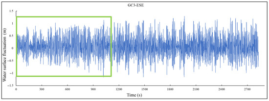
Figure 6.
Surface fluctuation curve of probe GC3 under an ESE incident wave. (The green box is an example of the statistical sample window of characteristic wave height).
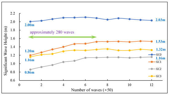
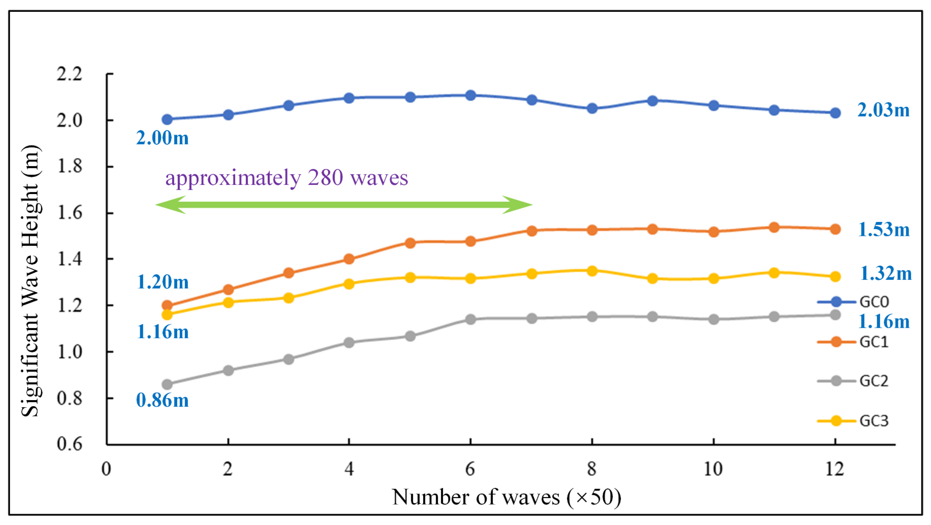
Figure 7.
Evolution of significant wave height under an ESE incident wave.
The results show the wave duration has a negligible influence on the wave height evolution at the harbor gate, while it has an obvious influence on the wave height evolution inside the harbor. The significant wave height at the harbor gate (GC0) does not increase with the increase in wave duration, which is mainly related to the small influence of wave reflection by banks. The significant wave height at the three berths (GC1, GC2, and GC3) first increased and then stabilized with the increase in wave duration, showing a significant development process. The wave at the three berths reaches a stable state after approximately 280 waves, and the significant wave height can reach 1.01–1.35 times that of the initial stage; their values are 1.53 m, 1.16 m, and 1.32 m, respectively. The significant height of the incident wave from the open sea attenuated significantly after passing into the harbor. In addition, observation also showed that the incident angle of the immersed element at each berth with the wave is different. The immersed element moored at berth GC1 or berth GC2 is mainly affected by the longitudinal wave, while the immersed element moored at berth GC3 is mainly affected by the transverse wave.
3.2. Dynamic Responses of a Single Element
The mooring scheme of a single immersed element mooring is shown in Figure 8. It should be noted that the initial tension force of each mooring cable in the test is adjusted to 30 kN, and under this initial tension level, the cable is basically in a catenary state.
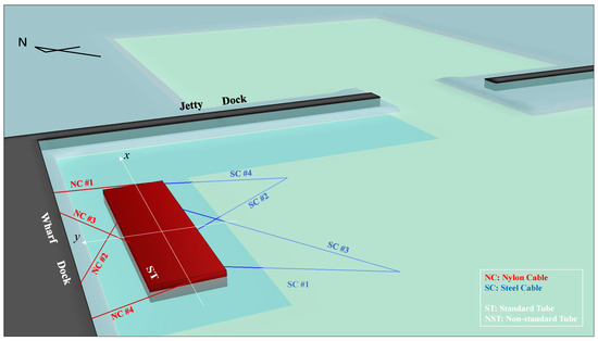
Figure 8.
Mooring scheme for a standard immersed element moored at berth GC3 near the wharf.
3.2.1. Under Wind Conditions
The wind not only acts directly on the freeboard of the immersed element but also indirectly on the immersed element in the form of wind-generated surface waves. The immersed element moves under the action of the wind, and the mooring system will produce a reverse restraining force to restrict this displacement. As the cables are long and have a very small initial tension, all the cables show a catenary state (no obvious tensioning) in the initial state. When the immersed element begins to displace, first the catenary shape of the cable changes while the tension deformation of the cable itself is small; that is, the tension force of each cable along the cable axis does not change significantly, but the direction of cable force at the mooring point of the immersed element changes with the increase in displacement. With the continuous increase in displacement, the catenary form of the cable will no longer change significantly when the cable is significantly tensioned, and the continuous increase in displacement will be reflected in the tension deformation of the cable itself, resulting in an increase in cable tension force. In general, the tension force-deformation curve of a mooring cable shows the following characteristics. As the displacement gradually increases, the cable tension force does not obviously change at the beginning until the catenary shape of the cable no longer changes significantly. Then, with the continuous increase in displacement, the cable tension force presents its own characteristics of force with deformation.
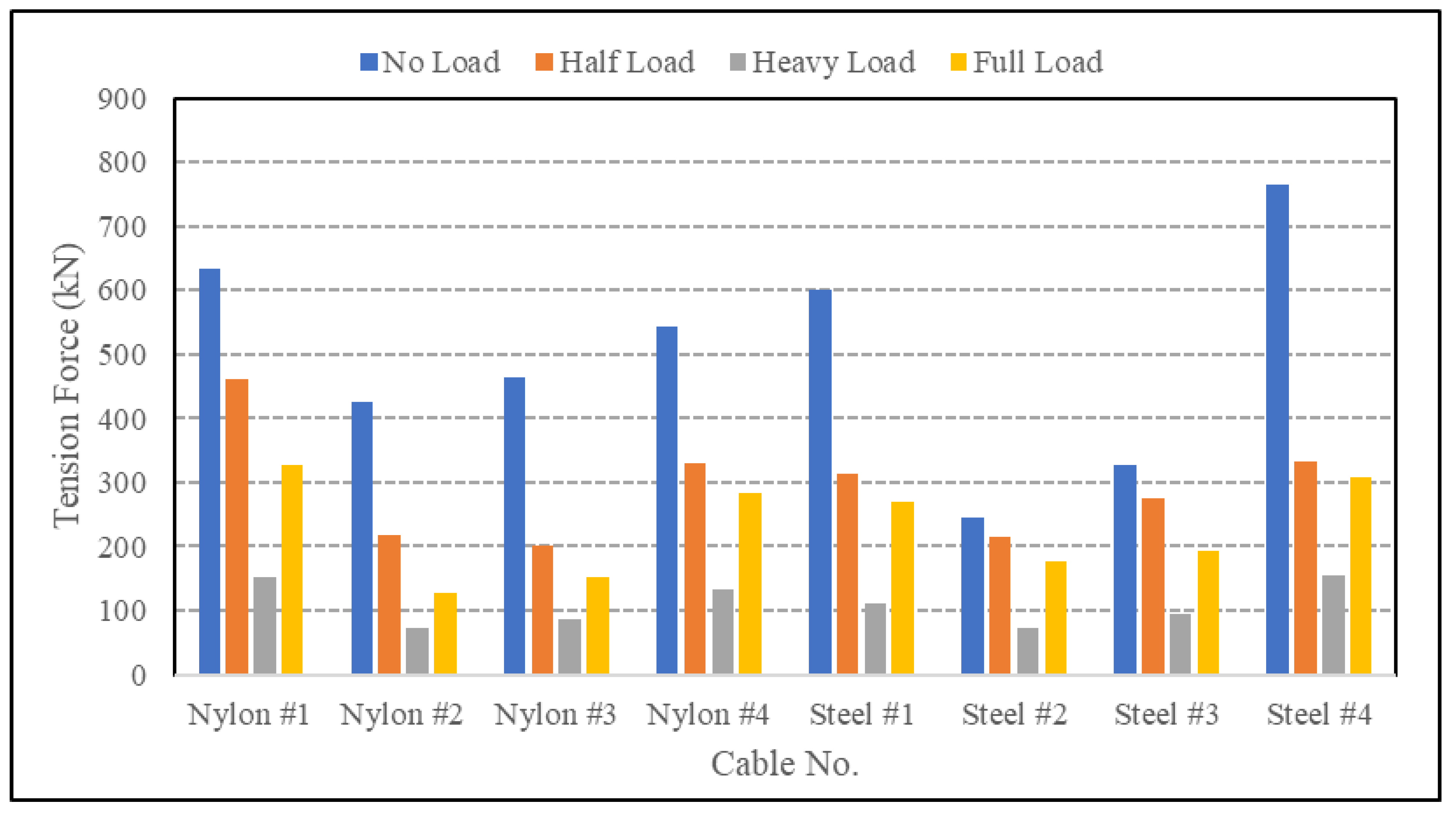
The maximum tension force of each cable under wind action is shown in Figure 9. The test results show that the cable on the leeward side has no force, and the wind force is borne by the windward cables. For various load conditions, the wind force on the immersed element is the largest under a no-load condition. The maximum tension force of the nylon cable reaches 635 kN, and the maximum tension of the steel cable reaches 765 kN. The order of the cable tension force under different load conditions is no-load > half-load > full-load > heavy-load. The wind force acting on the pontoons and the survey towers is relatively significant. The cable tension force under a full-load condition is generally about two times that as compared to a heavy-load condition.
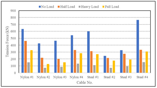
Figure 9.
Maximum tension force of mooring lines with a single immersed element moored under wind action.
Under the action of wind, the immersed element moves toward the leeward side, and a net displacement exists, accompanied by a small amplitude oscillation that is a result of the wind-generated surface wave. The maximum values of the immersed element motion components are listed in Table 6. The sway under offshore wind action is obviously greater than that under inshore wind action, which is closely related to the different compositions of the cable material on the leeward and windward sides. The maximum sway is 3.42 m under a no-load condition with offshore wind action.
Table 6.
Motion extremums of a standard immersed element under wind action (center of mass).
3.2.2. Under Wave Conditions
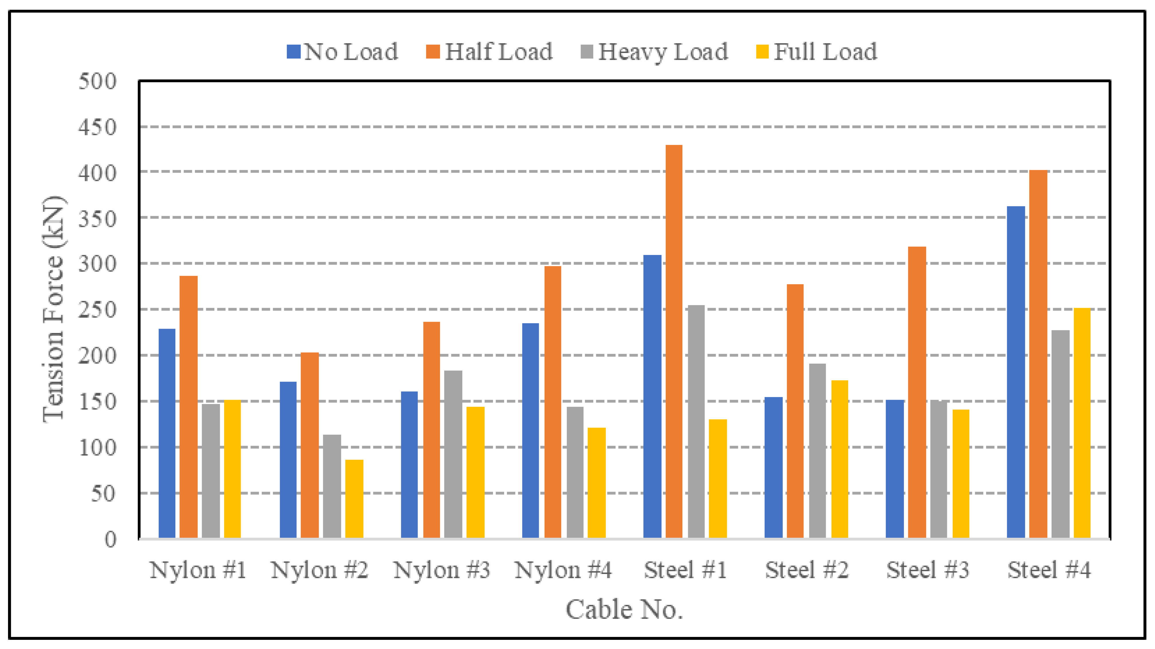
The maximum tension force of each cable under wave action is shown in Figure 10. For different loading conditions, the cable tension force of the standard element reaches its maximum under a half load condition, in which the maximum tension of the nylon cable reaches 297 kN and that of the steel cable reaches 429 kN. The order of the cable force under different load conditions is: half load > no load > heavy load > full load.

Figure 10.
Maximum tension force of mooring lines with a single immersed element moored under wave action.
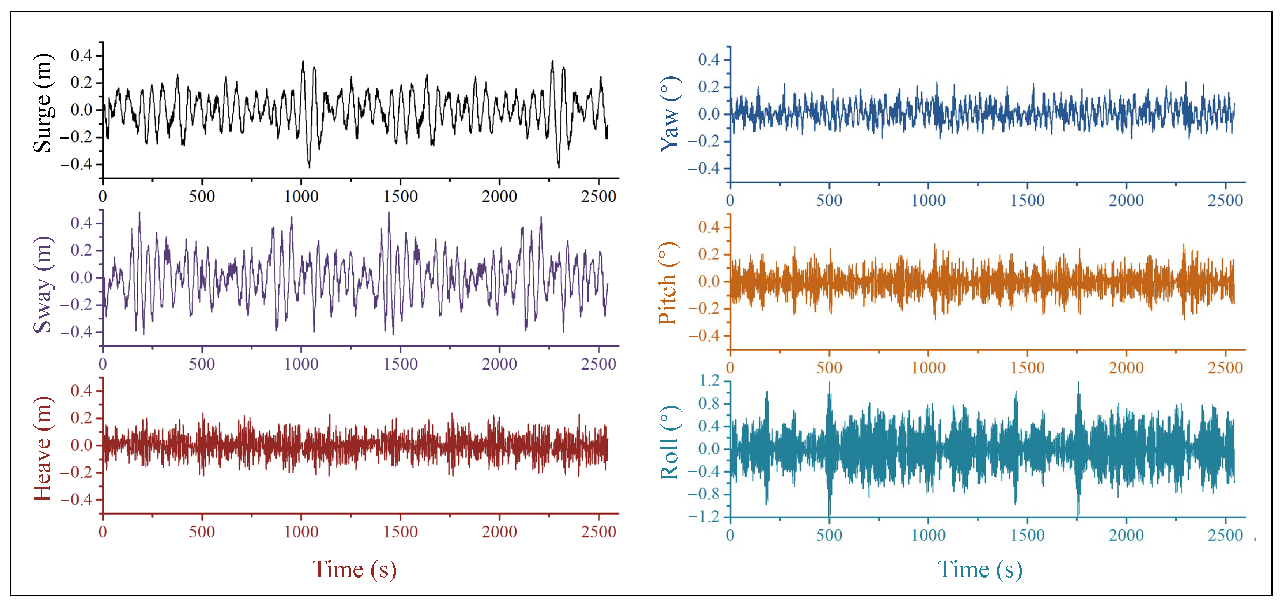
The typical time-domain motion curves of the immersed element under wave action are shown in Figure 11. The element motion curves all present obvious characteristics of low frequency (corresponding to the natural period of the mooring system) and are superimposed with high frequency (corresponding to the wave period). For the sway and surge components, the low frequency is dominant; however, for all other motion components, the high frequency is dominant. Additionally, the high frequency of roll is the most obvious among these components.
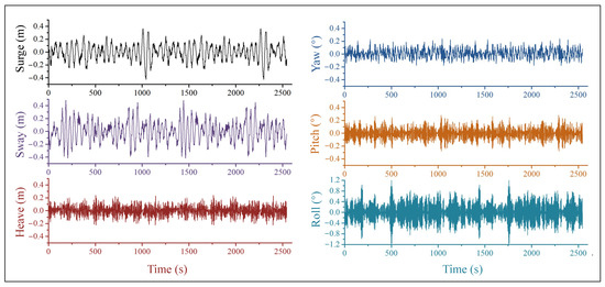
Figure 11.
Typical time domain curves of an immersed element motion under wave action (no load condition).
The motion extremums of the moored, immersed element are listed in Table 7. Under each load condition, the maximum values of sway under wave action are smaller than those under wind action, while the maximum values of roll are inverse.
Table 7.
Motion extremums of a standard immersed element under wave action (center of mass).
3.2.3. Under the Superposition of Wind and Waves
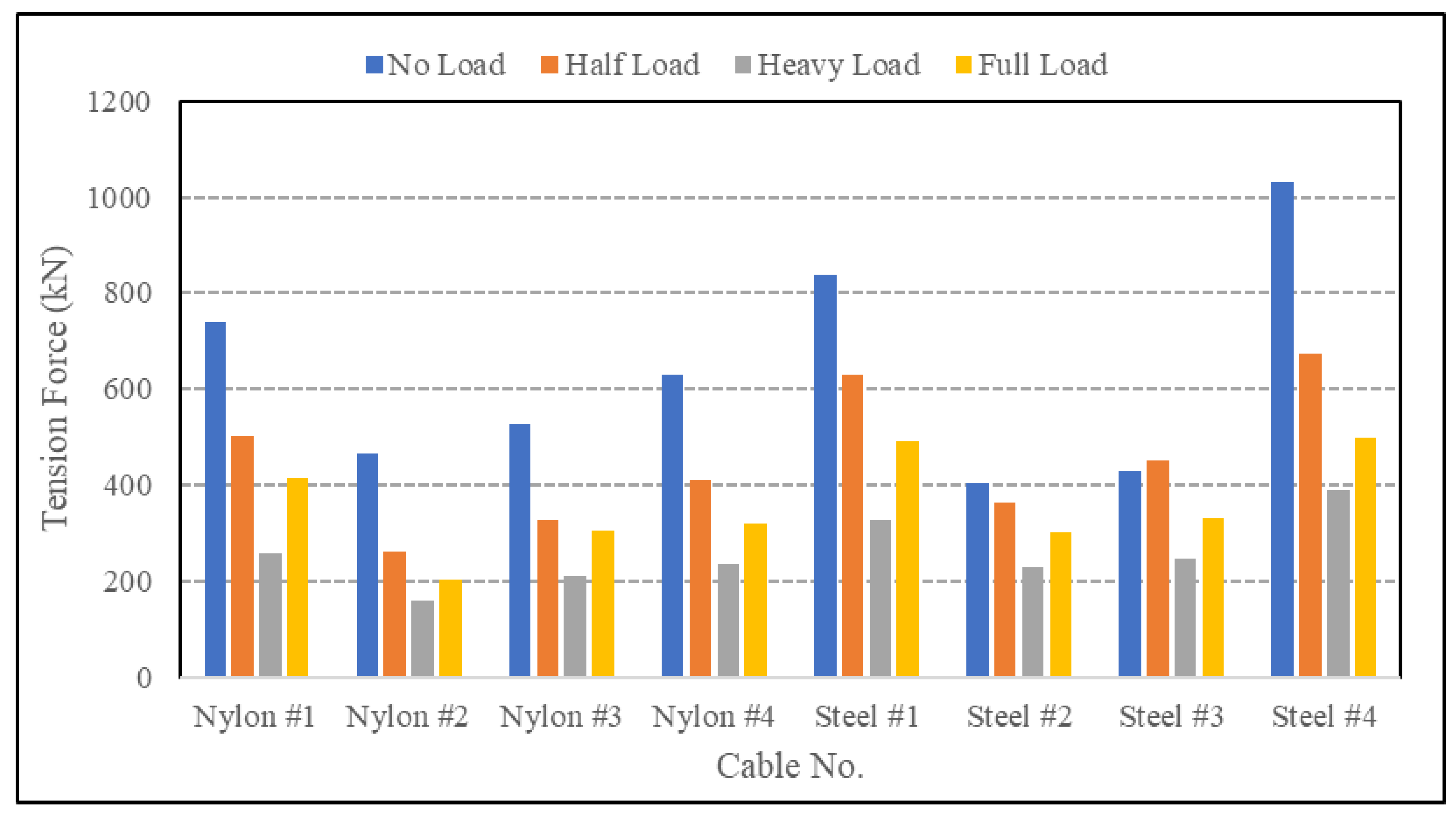
The maximum tension force of each cable under the superposition action of wind and waves is shown in Figure 12. The test results show that under the action of wave-superimposed wind, the cable on the leeward side is not tensioned, which is similar to that under wind action. For various load conditions, the cable force under a no-load condition is the largest, among which the maximum tension of nylon cable reaches 738 kN and the maximum tension of steel cable reaches 1032 kN, and the cable force under different load conditions is ranked as no load > half load > full load > heavy load.
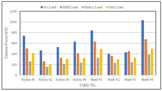
Figure 12.
Maximum tension force of mooring lines with a single immersed element moored under wind and wave action.
Under the combined action of wind and wave, the motion curves show both the characteristics under wind action and those under wave action, and the amplitude oscillation is greater than that under wind action due to a relatively greater wave intensity. The motion extremums of a moored, immersed element are listed in Table 8. The most significant motion response amplitudes are sway and roll. These two components obtain their extremums under a no-load condition with offshore wind and superimposed waves, where the extremums are 4.25 m and 1.77°, respectively. By comparing the results of tests under wind action and wave action, the main factor that leads to the dynamic response of the immersed element is the wind force, and the maximum cable force is found in the steel cables tied at the bow and stern of the immersed element.
Table 8.
Motion extremums of a standard immersed element under wind and wave action (center of mass).
3.3. Dynamic Responses of the Two Elements
3.3.1. Mooring with a Large Spacing
The mooring scheme for the simultaneous mooring of two immersed elements (a standard element moored at berth GC3 near the bank wharf and a non-standard element E32 moored at berth GC1 near the dike wharf) at a relatively long distance (slightly more than one time the length of the immersed element) is shown in Figure 13.
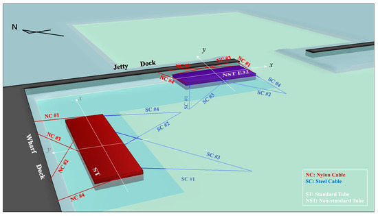
Figure 13.
Mooring scheme for a standard immersed element moored at berth GC3 near the wharf and a non-standard immersed element E32 moored at berth GC1 near the jetty.
Compared with the results of the mooring test of a single element, the cable tension force and motion extremums of the standard element under the two elements mooring simultaneously are slightly smaller overall, and the relative changes of the maximum cable tension force and motion extremums are shown in Table 9. The relative changes in maximum tension force in the transverse cables are greater than those in the longitudinal cables. Additionally, this corresponds well with the relative changes of the motion component (as listed in Table 10), in which changes in roll are more obvious. When the non-standard element E32 is moored at berth GC1 near the harbor gate, it has a shielding effect on the rear waters, similar to the floating breakwater. Therefore, the wave action on the standard element moored at berth GC3 in the rear water is weakened, resulting in a relatively smaller dynamic response amplitude. However, the reduction is very limited because the immersed element itself has no obvious influence on the short-period waves. Because of the randomness of irregular waves and the statistical uncertainty of test data, some dynamic responses of the element show slight increases, and that is reasonable. No obvious correlation is found between the relative changes in dynamic response and the load condition. The comparison of test results between a single-element mooring and a two-element mooring with a large spacing indicates that when two elements are berthed simultaneously, a distance of approximately one time the element’s length is sufficient for mooring safety and there is no mutual interference, which would make mooring conditions worse.
Table 9.
Relative change of the cable tension force of a standard element under two elements mooring simultaneously with a large spacing.
Table 10.
Relative change of motion response of a standard element under two elements mooring simultaneously with a large spacing.
3.3.2. Mooring with a Smaller Spacing
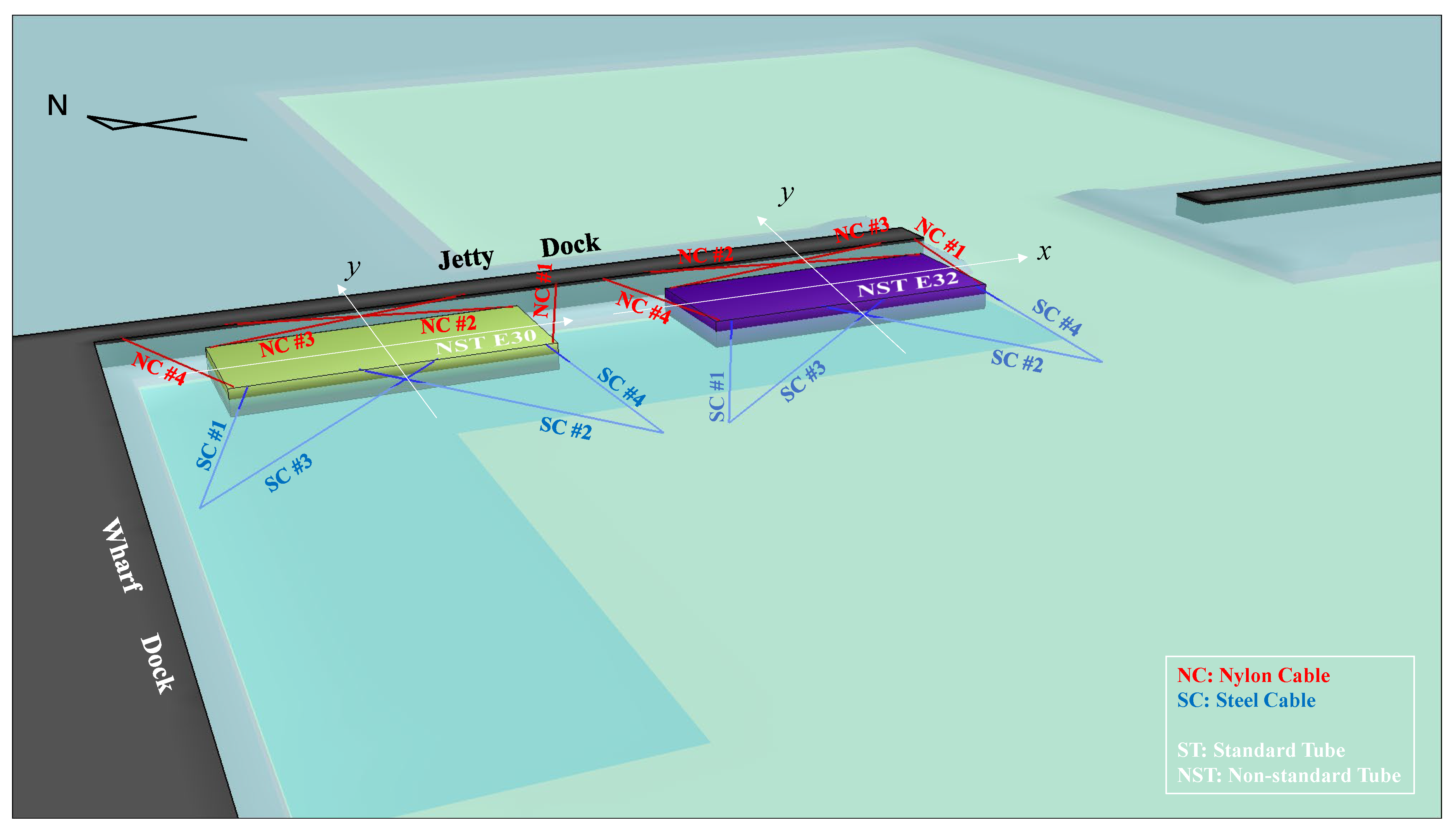
The mooring scheme for the simultaneous mooring of two immersed elements (a non-standard element moored at berth GC1 near the harbor gate and a non-standard element E30 moored at berth GC2 near the jetty) at a relatively short distance (approximately 0.5 times the length of an immersed element) is shown in Figure 14.

Figure 14.
Mooring scheme for a non-standard immersed element E32 moored at berth GC1 and a non-standard immersed element E30 moored at berth GC2.
The results of E32 are basically consistent with those of E32 when the two elements are moored at a relatively long distance apart. The relative changes in the dynamic response of the E32 element are shown in Table 11 and Table 12. The magnitudes of relative changes are within 5%. It indicates that the interference between the elements can be ignored when the two elements are moored simultaneously at such a distance.
Table 11.
Relative change of the cable tension force of non-standard element E32 under two elements mooring simultaneously with a small spacing.
Table 12.
Relative change of motion response of a non-standard element E32 under two elements mooring simultaneously with a small spacing.
4. Discussion
In this paper, physical model tests of an immersed tunnel element moored inside the harbor were conducted, and the influences of environmental factors (including wind, wave, wind, and wave combination) and tunnel element load conditions (including no load, half load, heavy load, and full load, each of which corresponds to a different freeboard-to-draft ratio) on the dynamic responses were investigated. The mutual interference of multiple elements moored simultaneously inside the harbor was also analyzed.
The dynamic response characteristics presented in the current experiments match those observed in earlier studies conducted in open-water situations [1,13,14]. Both show that tunnel motion under waves presents obvious characteristics of low frequency (corresponding to the natural period of the mooring system) superimposed with high frequency (corresponding to the wave period); low frequency is dominant in sway and surge, and high frequency is dominant for other motion components. The wind loads acting on the tunnel element are consistent with the theoretical results, especially when the freeboard-to-draft ratio is high. Figure 15 shows the experimental results and theoretical results of the element wind load under different freeboard-to-draft ratios (corresponding to different load conditions). The experimental results of the wind load calculated from the nylon cable side are very close to those from the steel cable side, and the variation trend with the freeboard-to-draft ratio is consistent with that of the theoretical results. The experimental results at a freeboard to draft ratio of 0.03 seem a little strange, but they are reasonable. As a freeboard to draft ratio of 0.03 corresponds to a full load condition, in this situation there are two pontoons and two survey towers located on it, resulting in an increased wind area as well as an increased wind load compared with that of a heavy load condition. Figure 15 also indicates that the difference between the experimental results and the theoretical results decreases with the increase of the freeboard-to-draft ratio; this is also reasonable. The wind not only acts directly on the freeboard but also indirectly on the tunnel element in the form of a wind-generated surface wave. The proportion of wind-generated wave force in the total wind load will decrease with the increase in freeboard resulting in a progressively smaller difference as the freeboard-to-draft ratio increases.

Figure 15.
Experimental and theoretical results of an element wind load under different free-board-to-draft ratios (3 s average speed of 47.4 m/s is used and the wind drag coefficient of 1.0 is adopted for theoretical estimation).
It is somewhat surprising that under wave action, the half-load condition is the most unfavorable of the investigated load conditions. The result under no load is close to that under half load, while the results under heavy load and full load are much smaller than those under half load. A possible explanation for this might be that under no-load and half-load conditions, the centers of gravity are relatively high, resulting in relatively poor static and dynamic stability and greater motion responses and tension forces in cables. Previous studies on the dynamics of an immersed tunnel element under waves mainly focused on the situation with a small freeboard; the influence of the freeboard-to-draft ratio on the dynamics did not get enough attention. The current study indicates that the freeboard-to-draft ratio has a significant influence on the dynamic response of tunnel elements, and the most dangerous situation may not be in the small freeboard situation. The findings have extended our knowledge of the dynamic response characteristics of tunnel elements, which are especially useful for the mooring design of the element with a floating pouring prefabrication method.
In the current study, tests on the dynamic response of multiple elements moored simultaneously inside the harbor were also conducted; two distances were chosen, and no adverse mutual interference was found. While it should be noted that the distance adopted was greater than 0.5 times the tunnel element length and the mooring position inside the harbor was fixed in a certain region. Therefore, it is impossible to determine the hydrodynamic interaction between the tunnel elements moored simultaneously at any position in the harbor basin with a smaller spacing, according to the current study. It is of great significance to carry out in-depth research on this issue.
It should be noted that mooring arrangement schemes may also affect the dynamic response of an immersed element, but this is not investigated in this paper. Another issue that should be paid attention to is that when mooring inside a harbor, the incident wave is usually greatly weakened due to the shielding effect of the harbor structure, but the wind is generally not affected. This is an essential difference between the environmental conditions of mooring inside a harbor and mooring in the open sea. Therefore, when the load on the immersed element is small, corresponding to a large area exposed to the wind, the effect of the wind may be far greater than that of the waves. Mooring stability of a no-load immersed element under wind action needs special attention.
5. Conclusions
In this study, the dynamic responses of an immersed element moored inside a harbor were studied by physical model tests. The wave height development process inside a harbor was determined by a wave evolution test. The influences of environmental factors, element load conditions, and mooring spacing on the dynamic response characteristics were examined. According to the research, the following conclusions can be drawn:
- (1)
- The incident wave attenuates significantly after passing into the harbor, and it takes a period of time for the incident wave from the harbor gate to reach a relatively stable state;
- (2)
- The dynamic response characteristics of a moored, immersed element are different under different environmental load types. With the wind action, the element experiences a net sway toward the leeward side, a small amplitude oscillation occurs, and the wind load is borne by the windward cables. With the wave action, the motion response of an immersed element includes a high-frequency part and a low-frequency part, and the cable on both sides will be tensioned. With the combined action of both wind and wave, both the characteristics under wind action and those under wave action are reflected;
- (3)
- The dynamic response of a moored tunnel element varies with the load condition (or freeboard-to-draft ratio). With wind action, the dynamic response is positively correlated with the freeboard-to-draft ratio and reaches its maximum amplitudes under a no-load condition. With wave action, the dynamic response under half-load and no-load conditions is significantly greater than that under heavy load or full load conditions;
- (4)
- No adverse mutual interference was found when the two elements were moored simultaneously at a distance far apart at approximately one times the element length or at a near distance at approximately half the element length inside the harbor. Simultaneous mooring of multiple tunnel elements inside the harbor is a potentially feasible scheme with appropriate spacing between each other.
Author Contributions
Conceptualization, Q.O. and Y.H.; data curation, Y.H.; formal analysis, Y.H.; funding acquisition, S.S. and J.M.; investigation, Q.O., Y.H., S.S. and W.P.; methodology, Y.H. and J.M.; project administration, B.Y.; supervision, B.Y.; validation, C.Q. and W.P.; visualization, Q.O., Y.H. and J.M.; writing—original draft, C.Q.; writing—review and editing, Q.O. All authors have read and agreed to the published version of the manuscript.
Funding
This research was funded by the R&D project in key areas of Guangdong Province (2019B111105002), the National Key R&D Program of China (2022YFB2602800), and the Technology Project of Anhui Province Group Limited for Yangtze-to-Huaihe Water Diversion (Contract No. YJJH-ZX-20220705481).
Institutional Review Board Statement
Not applicable.
Informed Consent Statement
Not applicable.
Data Availability Statement
The data presented in this study are available from the corresponding author upon request.
Acknowledgments
This physical model test was conducted in the experimental harbor basin of the Tianjin Research Institute for Water Transport Engineering.
Conflicts of Interest
The authors declare no conflict of interest.
References
- Xiao, L.F.; Yang, J.M.; Li, R.P. Experimental Study on Mooring, Towing and Installing of Immersed Tunnel Caissons. J. Shanghai Jiaotong Univ. (Sci.) 2010, 15, 103–105. [Google Scholar] [CrossRef]
- Chen, K.; Sheng, P.; Wu, W.; Li, T.; Xiong, A. Model Test of Immersed Tunnel Element in Towing Tank in Winds, Waves and Currents. In Proceedings of the Twenty-Second International Offshore and Polar Engineering Conference, Rhodes, Greece, 20–25 June 2021. [Google Scholar]
- Lv, W.Q.; Wu, W.G.; Su, L.W.; Chen, K.Q.; Peng, S. Hydrodynamic experimental study on immersed tube tunnel element of Hong Kong-Zhuhai-Macao Bridge. China Civ. Eng. J. 2014, 47, 138–144. [Google Scholar]
- Lv, W.Q.; Ying, Z.Q.; Su, L.W.; Lin, M.H. Hydrodynamic analysis of added resistance in waves of immersed tunnel elements during floating transportation. Port Waterw. Eng. 2011, 11, 1–5. [Google Scholar]
- Sheng, P.; Wu, W.; Chen, K.; Xiong, A.; Xia, Z. Experimental Investigation on Element Immersing Process of Immersed Tube Tunnel of Hong Kong-Zhuhai-Macao Bridge. In Proceedings of the ASME 31st International Conference on Ocean, Offshore and Arctic Engineering, Rio de Janeiro, Brazil, 1–6 July 2012; pp. 383–389. [Google Scholar]
- Su, L.W.; Kang, L. Hydraulic Analysis of Immersed Tunnel Element’s Immersion and its Application. Adv. Mater. Res. 2011, 250–253, 2360–2365. [Google Scholar] [CrossRef]
- Wu, R.D.; Ying, Z.Q.; Wang, Z.; Su, L.W. Model Test for Hydrodynamic Parameters of Immersed Tube Tunnel in Static Water. Appl. Mech. Mater. 2013, 477–478, 754–758. [Google Scholar] [CrossRef]
- Yang, C.; Wang, Y.X.; Zuo, W.G. Numerical simulation on the motion of immerged tunnel element with different arrangement types of mooring lines. Ocean. Eng. 2014, 32, 32–40. [Google Scholar]
- Yang, C. A Hydrodynamic Numerical Study on the Immersion Motion of Tunnel Element with Mooring Lines. Ph.D. Thesis, Dalian University of Technology, Dalian, China, 2013. [Google Scholar]
- Shao, Z.A. Experimental Investigation on the Cable Tension of Tunnel Element under Mooring Condition. Ph.D. Thesis, Dalian University of Technology, Dalian, China, 2011. [Google Scholar]
- Wu, Z.W.; Liu, J.K.; Liu, Z.Q.; Lu, Z.R. Nonlinear wave forces on large-scale submerged tunnel element. Mar. Struct. 2016, 45, 133–156. [Google Scholar] [CrossRef]
- Shi, H.D.; Li, S.Y.; Wang, D. Study on the Motions and Stress of Immersing Tunnel Element under Wave Actions. Appl. Mech. Mater. 2013, 328, 614–622. [Google Scholar] [CrossRef]
- Song, Y.; Huang, G.; Zhang, N.; Pei, Y. Experimental study on the mooring tension of tunnel element during immersion standby. Ocean Eng. 2016, 112, 25–32. [Google Scholar] [CrossRef]
- Song, Y.; Huang, G.X.; Pei, Y.G.; Shi, X.Y.; Zhang, N.C.; Lin, L.Y. Dynamic Responses of Immersing Tunnel Element During Freeboard Elimination. Int. J. Offshore Polar Eng. 2014, 24, 262–268. [Google Scholar]
- Ning, J.J.; Zhu, L.; Li, J. Comparison of anti-typhoon modes for super-large immersed tube. China Harb. Eng. 2018, 38, 52–56. [Google Scholar]


Disclaimer/Publisher’s Note: The statements, opinions and data contained in all publications are solely those of the individual author(s) and contributor(s) and not of MDPI and/or the editor(s). MDPI and/or the editor(s) disclaim responsibility for any injury to people or property resulting from any ideas, methods, instructions or products referred to in the content. |
© 2023 by the authors. Licensee MDPI, Basel, Switzerland. This article is an open access article distributed under the terms and conditions of the Creative Commons Attribution (CC BY) license (https://creativecommons.org/licenses/by/4.0/).