Article

Spin–Orbital Transformation in a Tight Focus of an Optical Vortex with Circular Polarization

by
Victor V. Kotlyar
1,2,
Sergey S. Stafeev
1,2,
Vladislav D. Zaitsev
1,2,
Alexey M. Telegin
1,2 and
Elena S. Kozlova
1,2,*
1
Laser Measurements Laboratory, Image Processing Systems Institute of the RAS—Branch of FSRC “Crystallography & Photonics” of the RAS, 151 Molodogvardeyskaya St., Samara 443001, Russia
2
Technical Cybernetics Department, Samara National Research University, 34 Moskovskoe Shosse, Samara 443086, Russia
*
Author to whom correspondence should be addressed.
Appl. Sci. 2023, 13(14), 8361; https://doi.org/10.3390/app13148361
Submission received: 3 July 2023 / Revised: 13 July 2023 / Accepted: 17 July 2023 / Published: 19 July 2023
(This article belongs to the Special Issue Optical Effects in Sharp Focus)

Abstract

:
In the framework of the Richards–Wolf formalism, the spin–orbit conversion upon tight focusing of an optical vortex with circular polarization is studied. We obtain exact formulas which show what part of the total (averaged over the beam cross-section) longitudinal spin angular momentum is transferred to the total longitudinal orbital angular momentum in the focus. It is shown that the maximum part of the total longitudinal angular momentum that can be transformed into the total longitudinal orbital angular momentum is equal to half the beam power, and this maximum is reached at the maximum numerical aperture equal to one. We prove that the part of the spin angular momentum that transforms into the orbital angular momentum does not depend on the optical vortex topological charge. It is also shown that by virtue of spin–orbital conversion upon focusing, the total longitudinal energy flux decreases and partially transforms into the whole transversal (azimuthal) energy flow in the focus. Moreover, the longitudinal energy flux decreases by exactly the same amount that the total longitudinal spin angular momentum decreases.

1. Introduction

In modern optics, many optical effects are based on the interaction between the polarization of light and the vortex phase of light. A review on spin–orbital conversion (SOC) (interaction, coupling) in photonics can be found in [1]. By SOC, we mean the ability of light with circular polarization to create a rotation of the transverse energy flow. The spin–orbital transformation underlies the spin Hall effect in an inhomogeneous medium [2], upon reflection from the interface between two media [3,4,5], tight focusing [6,7,8,9,10], light scattering [11,12,13], and while light transmission through waveguides [14,15,16], anisotropic crystals [17,18], metasurfaces [19,20,21], and in nanostructures [22,23,24]. Due to SOC, excitation of optical vortices was observed in the nanodisk laser when the disk was excited by light with circular polarization [25]. The spin Hall effect was experimentally observed as a submillimeter Imbert–Fedorov shift when light was reflected from the surface of a birefringent symmetric planar waveguide with a metal shell [26]. Light in free space demonstrates an intrinsic quantum spin Hall effect when surface modes with strong spin–momentum locking are formed [27]. A review of works on SOC in optics is presented in [28]. Due to SOC, when light with linear polarization is reflected from twisted few-layer hyperbolic metasurfaces, two shifted beams with circular polarization of different directions are formed [29]. In this case, when a beam with circular polarization propagates at an angle to the optical axis, then the transverse flow of the Poynting vector through a plane perpendicular to the optical axis will be displaced or separated. In [30], this phenomenon was called the geometric spin Hall effect. If a paraxial vortex beam with cylindrical vector polarization is limited by a sector diaphragm, that is, the circular symmetry of the beam is broken, then regions with left and right circular polarization appear in the transmitted beam [31]. The spin Hall effect also arises if a radially polarized laser beam passes through a sector diaphragm [32]. Then, regions with left and right circular polarization will be formed in the beam after passing the aperture. In the works listed above, the question of what part of the spin angular momentum (SAM) is transferred to the orbital angular momentum (OAM) is not considered. SAM is the spin density in the cross-section of the light beam. Light with linear polarization has no spin, i.e., SAM is zero. However, light with circular polarization has a maximum spin denseness, that is, SAM is equal to the power of the beam. The normalized to beam power SAM of circularly polarized light is plus one for right-hand polarization and minus one for left-hand circular polarization. The normalized SAM of light with elliptical polarization is less than one. OAM is a value that indicates the presence of a vortex energy flow in the beam. The normalized to the beam power OAM of vortex laser beams is equal to the topological charge. Therefore, spin–orbit transformation occurs when circularly polarized light that has SAM is converted into light with a vortex energy flow that has OAM.
SOC is a universal physical phenomenon and is present in many processes. For example, it is known that due to SOC, no collapse occurs during Bose–Einstein condensate [33]. That is, due to SOC, the initial Gaussian quantum state does not decrease to zero in a finite time, but transforms into a vortex state and increases in size with time.
In our study, within the Richards–Wolf formalism, exact formulas are obtained for the case of sharp focusing of a circularly polarized optical vortex. Here, we proposed right-hand circular polarization. These formulas show what part of the total longitudinal SAM transforms into the total longitudinal part of the OAM in the focus. It is also shown that the maximum part of the SAM that can convert into the OAM is equal to half of the beam power.

2. The Denseness of Lengthwise Projections of the SAM and OAM

The Jones vector for the electric and magnetic fields of the source beam have the form:
E ( ψ , ϑ ) = A ( ψ ) 2 exp ( i m ϑ ) ( 1 i ) ,     H ( ψ , ϑ ) = A ( ψ ) 2 exp ( i m ϑ ) ( i 1 ) ,
where A(ψ) is an amplitude of the radially symmetric launch field, (ρ,ϑ) are polar coordinates in the cross-section of the light beam, ρ = fcosψ, f is a focal length of a spherical lens. Figure 1 shows the optical scheme, which is studied in this work. The light beam from the laser acquires a linear polarization after the polarizer P1 and enters the light modulator SLM. The modulator has a transmission in the form of a diffraction grating with a fork. The number of teeth at the fork is equal to the topological charge of the optical vortex, which is formed after SLM. After a quarter wave plate, the optical vortex acquires circular polarization. Aperture D cuts out the working +1 order of diffraction that is formed by the grating. A microobjective focuses light onto a CCD-camera. Thus, the diagram in Figure 1 makes it possible to register the distribution of light intensity in the focus of the light field (1). In Figure 1, for definiteness, a wavelength of 633 nm is used. Simulation results will be also given for this wavelength, but the effect of spin–orbital transformation takes place for any wavelength.
The amplitudes in the proposed launch field (1) are given for right-hand circular polarization. At the source, the lengthwise projection of the SAM S z = 2 Im ( E x E y ) of the field (1) is equal to S z , 0 = A 2 ( ψ ) , and the total spin in the source plane is equal to the total energy (power) of the beam W:
S ^ z , 0 = 2 π 0 0 2 π A 2 ( ψ ) ρ d ρ = W
In reference [34], using the Richards–Wolf formalism [35], formulas for the intensity of the lengthwise component of the SAM in the focal plane were derived. The distributions of the intensity and the SAM lengthwise component of the focused field (1) will have the form:
I ( ρ , ϑ ) = | E x | 2 + | E y | 2 + | E z | 2 = γ 0 , m 2 + γ 2 , m + 2 2 + 2 γ 1 , m + 1 2 ,
S z = 2 Im ( E x E y ) = γ 0 , m 2 γ 2 , m + 2 2 .
Formulas (3) and (4) include functions Υξ,χ which rely only on the radial variable ρ:
γ ξ , χ = 2 k f 0 β sin ξ + 1 ( ψ 2 ) cos 3 ξ ( ψ 2 ) cos 1 / 2 ( ψ ) A ( ψ ) e i k z cos ψ J χ ( k ρ sin ψ ) d ψ ,
where k = 2π/λ is the wavenumber of light with the wavelength of λ; f is the focal length; β is the maximum inclination angle of the rays to the optical axis, which determines the numerical aperture of the aplanatic lens NA = sinβ; Jχ(sinψ) is the Bessel function of the first kind of χ -th order. In Expression (5) and below, the indices χ and ξ can get the next values: ξ = 0, 1, 2; χ = m − 2, m − 1, m, m + 1, m + 2.
By virtue of the circular polarization of the launch field in the focus, both the intensity (3) and the spin denseness (4) distributions have circular symmetry. In reference [15], an equation for the distribution of the OAM in the focus of the field (1) was obtained:
L z = Im ( E x E x ϑ + E y E y ϑ + E z E z ϑ )   = m γ 0 , m 2 + ( m + 2 ) γ 2 , m + 2 2 + 2 ( m + 1 ) γ 1 , m + 1 2 .
Adding Expressions (4) and (6), we obtain the sum of the lengthwise projections of the OAM and SAM:
J z = L z + S z = ( m + 1 ) ( γ 0 , m 2 + γ 2 , m + 2 2 + 2 γ 1 , m + 1 2 ) = ( m + 1 ) I .
Expression (7) shows that the lengthwise component of the sum of orbital and spin angular momenta in the focus of the field (1) is equal to the intensity (3) of light in the focus multiplied by the sum of the topological charge m and the “spin” of the launch field, which equals to 1.

3. The Total Lengthwise OAM and SAM Averaged over the Cross-Section of the Beam

In reference [36], an expression was obtained for the partial power of the angular harmonics included in (3), (4), and (7) in the form:
W ξ = 4 π f 2 0 β sin 2 ξ + 1 ( ψ 2 ) cos 5 2 ξ ( ψ 2 ) | A ( ψ ) | 2 d ψ .
Integrals (8) can be analytically calculated only in ordinary cases, but, nevertheless, it is possible to estimate the contribution of each angular harmonic. For instance, if a uniform field with a constant amplitude A(ψ) ≡ 1 is focused, then [36]:
W 0 = 4 π f 2 0 β sin ( ψ 2 ) cos 5 ( ψ 2 ) d ψ = 4 3 π f 2 [ 1 cos 6 ( β 2 ) ] , W 1 = 4 π f 2 0 β sin 3 ( ψ 2 ) cos 3 ( ψ 2 ) d ψ = 2 3 π f 2 sin 4 ( β 2 ) [ 1 + 2 cos 2 ( β 2 ) ] , W 2 = 4 π f 2 0 β sin 5 ( ψ 2 ) cos ( ψ 2 ) d ψ = 4 3 π f 2 sin 6 ( β 2 ) , W = 2 π f 2 [ 1 cos ( β ) ] .
In the limiting case, when the numerical aperture is close to unity, i.e., βπ/2, it can be obtained: W0 = (7/6)πf2, W1 = (1/3)πf2, W2 = (1/6)πf2. All energy coincides with the area of the hemisphere: W = W0 + W2 + 2W1 = 2πf2. It also should be noted that W0W2 =W/2.
Based on (3), (4), (7), and (8), we find the total (averaged over the cross-section of the whole beam) intensity (total beam power), the OAM, and the lengthwise SAM in the focal plane:
I ^ = W = 0 0 2 π I ( ρ , ϑ ) ρ d ρ d ϑ = 0 0 2 π ρ d ρ d ϑ ( γ 0 , m 2 + γ 2 , m + 2 2 + 2 γ 1 , m + 1 2 ) = W 0 + W 2 + 2 W 1 .
S ^ z = 0 0 2 π S z ρ d ρ d ϑ = 0 0 2 π ρ d ρ d ϑ ( γ 0 , m 2 γ 2 , m + 2 2 ) = W 0 W 2 .
L ^ z = 0 0 2 π L z ρ d ρ d ϑ = 0 0 2 π ρ d ρ d ϑ ( m γ 0 , m 2 + ( m + 2 ) γ 2 , m + 2 2 + 2 ( m + 1 ) γ 1 , m + 1 2 ) = = m W 0 + ( m + 2 ) W 2 + 2 ( m + 1 ) W 1 .
Expressions (10)–(12) are the main result of this study. It follows from them that the sum of the full longitudinal OAM and SAM is equal to:
S ^ z + L ^ z = m W 0 + ( m + 2 ) W 2 + 2 ( m + 1 ) W 1 + W 0 W 2 = ( m + 1 ) ( W 0 + W 2 + 2 W 1 ) = ( m + 1 ) W .
Equation (13) should be supplemented with a similar sum in the initial beam plane (1). To do this, we obtain the denseness of the lengthwise OAM component and the total longitudinal OAM in the launch plane from (1):
L z , 0 = Im ( E x E x φ + E y E y φ ) =   m | A ( ψ ) | 2 , L ^ z , 0 = 0 0 2 π L z , 0 ρ d ρ d ϑ = m W .
Adding (2) and (14), we obtain the sum of the OAM and SAM in the initial plane of the beam (1):
S ^ z , 0 + L ^ z , 0 = W + m W = ( m + 1 ) W .

4. The SOC upon the Light Focusing

Comparing (13) and (15), it can be seen that the sum of the total lengthwise projections of the OAM and SAM is conserved upon focusing. However, separately, the full longitudinal OAM and SAM are not conserved due to the SOC. The total SAM during focusing decreases and partially passes into the full OAM, which, in contrast, increases. It is especially evident when m = 0. In the launch plane, in this case, the total SAM is equal to the total beam power (1): S ^ z , 0 = W , and the total OAM is zero: L ^ z , 0 = 0 . During the focusing process, the total SAM will decrease and will be equal to (11) in the focus: S ^ z = W 0 W 2 , and the total OAM will grow and will be equal to (12) in the focus: L ^ z = 2 W 2 + 2 W 1 = W ( W 0 W 2 ) . Taking into account (9) and at βπ/2, the full longitudinal SAM will decrease in focus compared to the initial plane by 2 times ( S ^ z = W 0 W 2 =W/2), and the total longitudinal OAM will increase in focus compared to the initial plane, also by 2 times ( L ^ z = W / 2 ). This means, that, in the limiting case (A(ψ) = 1, β = π/2) with a plane wave with right-hand circular polarization focusing, half of the total longitudinal SAM will transform into a longitudinal OAM. For a smaller numerical aperture (β < π/2) and for any other real amplitudes A(ψ) < 1, with field (1) focusing, a part less than half will pass from the SAM to the OAM. From (9), it can be found how much the SAM and OAM change due to the SOC for the case with a smaller numerical aperture, for instance, at β = π/3 (m = 0, A(ψ) = 1). Then, we get that SAM and OAM in the focus will be equal to S ^ z = 3 W / 4 and L ^ z = W / 4 , respectively. That is, at a numerical aperture sin β = 3 / 2 0.87 , the limit value of the OAM that can occur in the focus of the field (1) is equal to one fourth of the total beam power.
It is clear that similar formulas can also be obtained for an optical vortex with left-hand circular polarization. Then, for an optical vortex with topological charge n and left circular polarization, instead of (11), (12), and (13) we get:
S ^ z = W 2 W 0 , L ^ z = m W 0 + ( m 2 ) W 2 + 2 ( m 1 ) W 1 , S ^ z + L ^ z = ( m 1 ) ( W 0 + W 2 + 2 W 1 ) = ( m 1 ) W .

5. Transformation of the Longitudinal Energy Flux into the Transverse Energy Flux

It is interesting to follow how the total longitudinal energy flux (the lengthwise Poynting vector component averaged over the beam cross-section) changes while tight focusing of the beam (1). It was shown in [36] that the distribution of the longitudinal Poynting vector component in the focus P z = Re ( E x H y E y H x ) is equal to the lengthwise projection of the SAM:
P z = S z = γ 0 , m 2 γ 2 , m + 2 2 .
Therefore, the total longitudinal energy flux averaged over the beam cross-section in the focus will be equal to (11):
P ^ z = 0 0 2 π P z ρ d ρ d ϑ = W 0 W 2 .
In the initial plane of the field (1), the denseness of the longitudinal energy flow and the total longitudinal energy flux are equal to the expressions:
P z , 0 = | A ( ψ ) | 2 , P ^ z , 0 = W .
It can be seen from a comparison of (18) and (19) that, upon focusing, the total longitudinal energy flux decreases in the same way as the total longitudinal SAM. Due to the fact that during focusing, a longitudinal component of the electric field strength Ez appears, a transverse energy flux also appears. This occurs simultaneously with the SOC. That is, a transverse energy flow appears as the SAM decreases and the OAM appears. This means that part of the initial longitudinal energy flux is converted into a transverse energy flux, and the longitudinal flux decreases by exactly the same amount as the longitudinal SAM decreases. It should be noted that that the value of the total longitudinal energy flux does not depend on the value of the topological charge, but depends only on the numerical aperture sinβ of the focusing optical system and on the initial radially symmetric amplitude A(ψ) of the light field. These facts follow from (8) and (18).

6. Separate Measurement of the OAM and SAM in the Focus

In reference [37], formulas are given that relate the force F and the moment of the force T , which influence on a Rayleigh (smaller than wavelength) microparticle with a complex permittivity ε, with the intensity I, the canonical vector of the energy flow P 0 , and the SAM vector S :
F = Re ( ε ) 4 I + Im ( ε ) 2 P 0 , T = Im ( ε ) 2 S .
In (20), we use next notation:
I = | E x | 2 + | E y | 2 + | E z | 2 , P = P 0 + P s = Re 8 π c ( E × H ) = Im 16 π c ( E ( ) E ) + 1 2 × S , S = Im 16 π c ( E × E ) ,
where c is the speed of light in vacuum and P s is the spin flow. Therefore, the method of separate measurement of the SAM and OAM in the focal plane of the field (1) is as follows. It follows from (3) that at m = 0, there is an intensity maximum I ( ρ = 0 ) = γ 0 , 0 2 in the focus center. The microparticle in focus will move to the center, where the intensity is maximal and the gradient is equal to zero. Due to the absorption of the particle (Imε ≠ 0), the moment of the force (20) effecting on the particle will rotate it around its center of mass and around the optical axis. The value of this moment of forces will be proportional to the lengthwise projection of the SAM vector: Tz ~ Sz. At a large numerical aperture (close to unity), the focal spot is smaller than the wavelength and the particle captured by such a focal spot will rotate under the influence of the total longitudinal component of the SAM equal to S ^ z = W 0 W 2 W / 2 . Therefore, by measuring the speed of the particle rotation, it is possible to estimate the force moment, which will be proportional to the SAM S ^ z . To measure the transverse energy flux Pφ, it is necessary to form a ring of light in the focus. It follows from (3) that at m = 1 the intensity on the optical axis will be zero in the focus, since I ( ρ = 0 ) = γ 0 , 1 2 + γ 2 , 3 2 + 2 γ 1 , 2 2 = 0 . This means that a light ring will form in the focus, because of the presence of an optical vortex with a topological charge m = 1. The particle in focus will shift to the ring due to the minimum intensity gradient on the ring, and the force Fϑ ~ Pϑ will shift this particle along the light ring. This force will be proportional to the transverse energy flow Pϑ, which, in turn, is proportional to the longitudinal component of the angular momentum and the lengthwise projection of the OAM: J z = L z = ρ P ϑ . It was shown in [36] that the distribution of the transverse flux in the focal plane of the field (1) is described by the expression P ϑ = γ 1 , m + 1 ( γ 0 , m + γ 2 , m + 2 ) . The speed of the particle moving along a ring of small radius will be influenced not by the full longitudinal OAM, but by a partial one, since the particle is captured not by the entire circular trajectory, but only by its part. By experimental estimation of the value of the light ring, which falls on the particle (γ < 1), it is possible to estimate the part of the total longitudinal OAM that is transferred to the particle γ L ^ z = γ ( 2 W W 0 + W 2 ) 3 γ W / 2 . This value can be found by measuring the average speed of the particle along the light ring in the focus of the field (1), since this speed v is proportional to the force (20), which is proportional to the transversal energy flow Pϑ, which is proportional to the longitudinal projection of the OAM L ^ z : v F P ϑ γ L ^ z .

7. Simulation Results

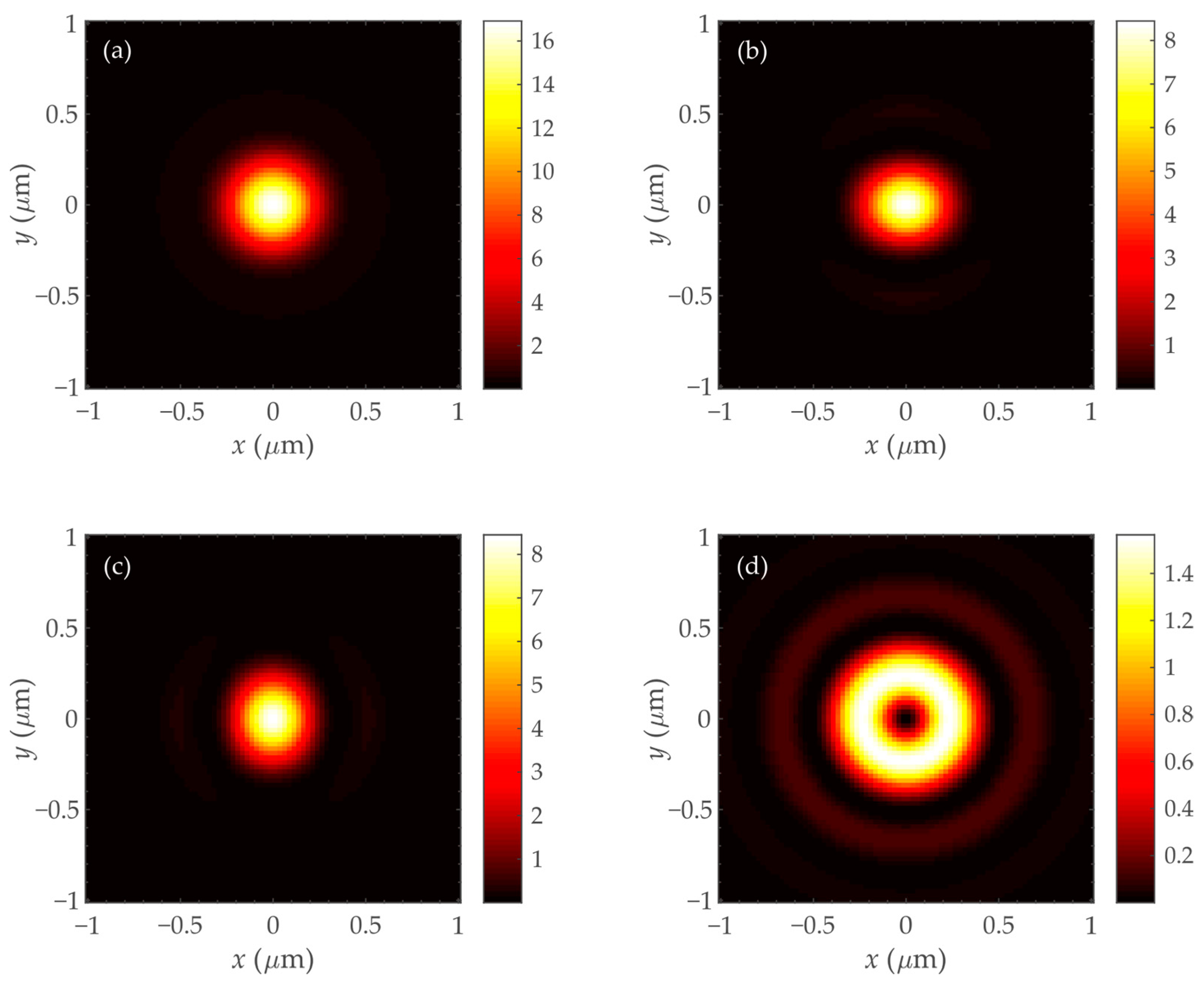
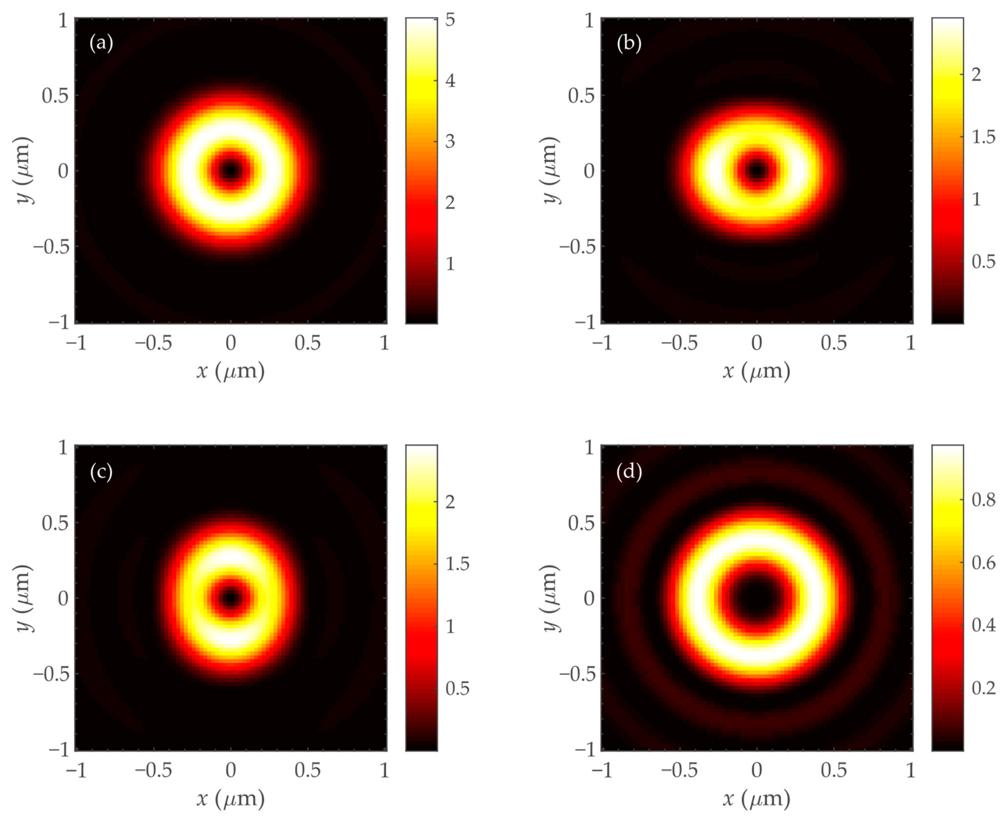
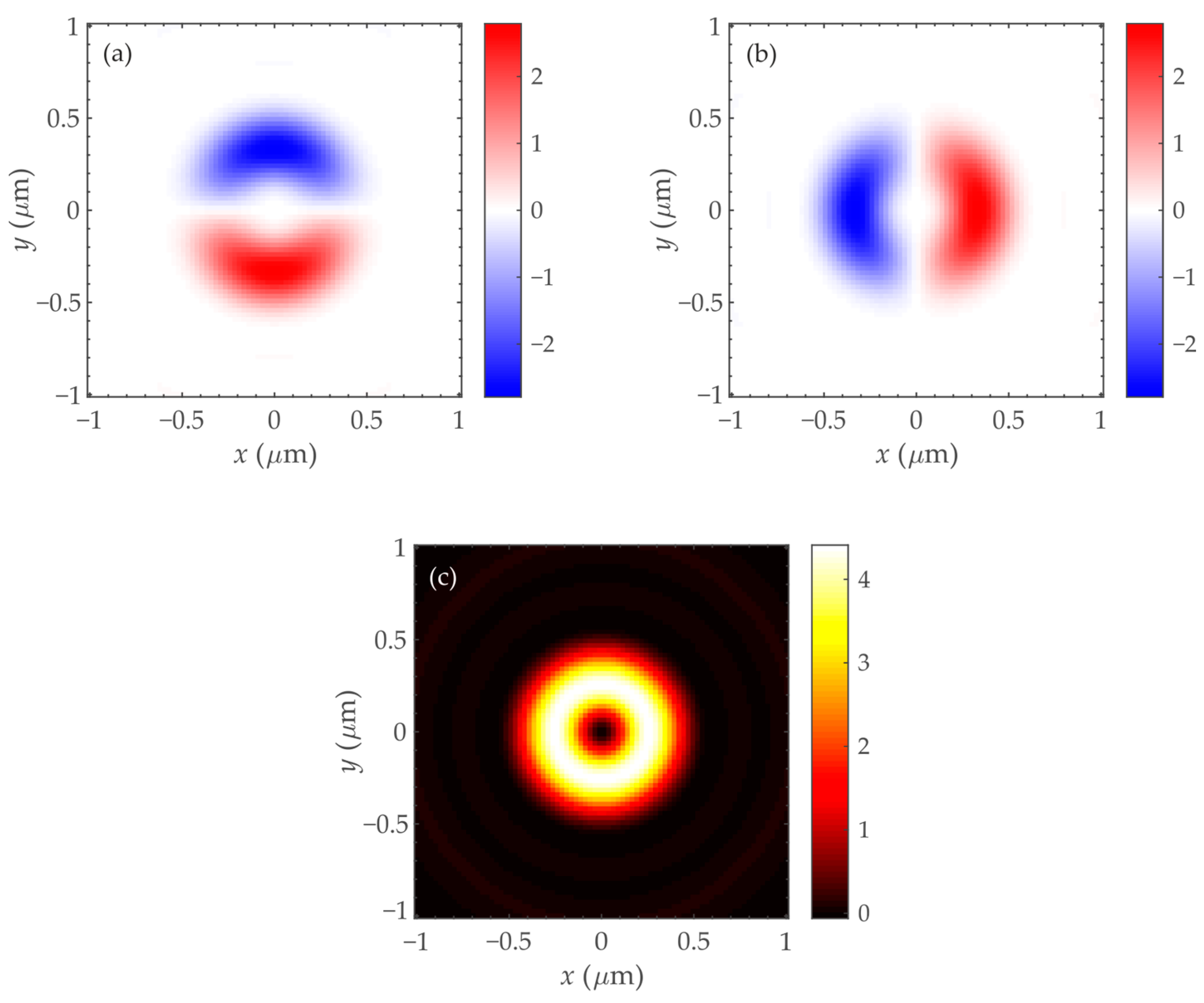
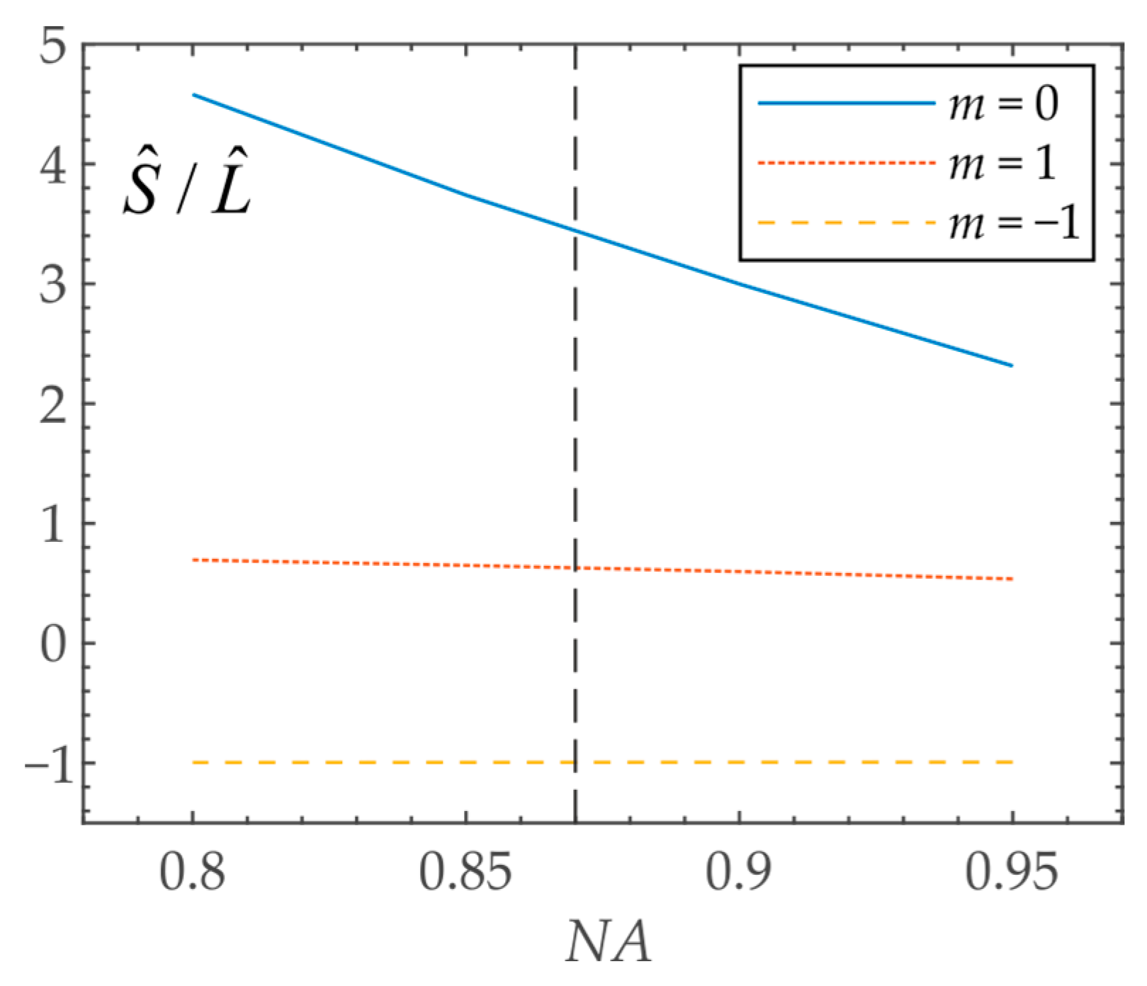
This section presents the results of numerical simulation of light field (1) focusing on different topological charges of incident beams. The simulation was performed by using the solution of the Richards–Wolf integral [35]. Focusing of light with a wavelength of 633 nm by aplanatic objectives was considered. This wavelength was chosen because it can be implemented in practice using a conventional helium–neon laser. As an example of the calculated patterns of intensity and SAM, the results of focusing for vortices with topological charges of m = 0 (no vortex) and m = 1 are presented. Figure 2 shows the intensity pattern and its individual components for m = 0. Patterns of the SAM vector components for the same topological charge (m = 0) are presented in Figure 3. Figure 4 and Figure 5 show the distribution of intensity and SAM for m = 1. Figure 6 shows the ratio S ^ z / L ^ z depending on the numerical aperture of the focusing lens. All figures are given for the numerical aperture of the focusing lens equal to NA = 0.95. Microobjectives with 100× magnification have such a numerical aperture. A large numerical aperture was chosen for modeling because the effect of SOC is noticeable starting from a numerical aperture of 0.8 and reaches a maximum at a numerical aperture of 1.
The comparison of Figure 2a and Figure 3c shows that at m = 0, the intensity I and the lengthwise SAM projection Sz in the focal plane are almost the same in shape (bright round spot) and in magnitude I max S z , max 16 . This follows from Equations (3) and (4), since I S z γ 0 , 0 2 , because it follows from (9) that γ 0 , 0 2 γ 2 , 2 2   ,     γ 0 , 0 2 2 γ 1 , 1 2 .
The comparison of Figure 4a and Figure 5c shows that at m = 1, the intensity I and the lengthwise SAM projection Sz in the focal plane have the form of a ring with approximately the same radius and size, although Sz,max ~ 4 is slightly less than Imax ~ 5. This follows from Equations (3) and (4): I = γ 0 , 1 2 + γ 2 , 3 2 + 2 γ 1 , 2 2   ,     S z = γ 0 , 1 2 γ 2 , 3 2 , taking into account (9): γ 0 , 1 2 γ 2 , 3 2   ,     γ 0 , 1 2 2 γ 1 , 2 2 .
Figure 6 shows the ratio of SAM to OAM S ^ z / L ^ z in the focus of light field (1) at different numerical apertures of a spherical lens and for different topological charges of incident light: m = 0 (line 1), m = 1 (line 2), m = −1 (line 3). In Section 4, specific values S ^ z and L ^ z were also obtained for the numerical aperture NA = 0.87. It is obtained that S ^ z = W 0 W 2 3 W / 4   ,     L ^ z W / 4 for m = 0, and S ^ z 3 W / 4   ,     L ^ z = W + W / 4 5 W / 4 for m = 1. Therefore, it can be seen from Figure 6 that for m = 0 S ^ z / L ^ z = 3, and for m = 1 S ^ z / L ^ z = 3/5 = 0.6 at a numerical aperture of 0.87. If n = −1, then S ^ z 3 W / 4   ,     L ^ z = W + W / 4 3 W / 4 , that is S ^ z =     L ^ z , and their ratio is equal to S ^ z / L ^ z = −1 for any numerical aperture. This can be seen from Figure 6 (curve 3). It means that an optical vortex with right circular polarization and a topological charge of −1 has no angular momentum, since the OAM and SAM are equal and have different signs.

8. Discussion

In tight focusing, SOC occurs when light passes through a spherical lens. If the optical vortex with the right circular polarization (1) before the spherical lens had a full longitudinal SAM S ^ z , equal to beam power W (2), then the total longitudinal SAM of the beam would decrease immediately after the spherical lens and become equal to (11) S ^ z = W 0 W 2 . After the spherical lens, beam (1) has three vortex harmonics [34]: exp(i), exp(i(m + 2)ϑ), and exp(i(m+1)ϑ), instead of one vortex harmonic exp(i). Therefore, the total beam power W after the spherical lens is distributed between these three harmonics W = W0 + W2 + 2W1. The vortex harmonic with the topological charge m + 1 has a linear polarization directed along the optical axis z. That is, it propagates perpendicular to the optical axis and does not contribute to the longitudinal projection of the SAM. An optical vortex with topological charge m + 2 has a left-hand circular polarization, and therefore its contribution to the longitudinal projection of the SAM will be negative. Therefore, the total longitudinal SAM of the beam (1) after the spherical lens is reduced by the sum of the powers of the indicated harmonics S ^ z , i n S ^ z , a f t e r = W ( W 0 W 2 ) = 2 ( W 1 + W 2 ) . This difference, by which the spin has decreased due to the SOC, is exactly equal to the amount by which the total longitudinal OAM, which the beam (1) did not have before the spherical lens if m = 0, has increased: L ^ z = 2 ( W 1 + W 2 ) . On the other hand, this is confirmed by considering the energy flow (the Pointing vector). Before the spherical lens, the beam (1) had only a longitudinal energy flux (19), which was equal to the beam power P ^ z = W . After a spherical lens, the longitudinal energy flux decreased and became equal to (18) P ^ z = W 0 W 2 . As well as for the spin S ^ z two new vortex harmonics exp(i(m + 2)ϑ) and exp(i(m + 1)ϑ), which are generated after the spherical lens, do not participate in the formation of the longitudinal energy flux. They do not participate in the formation of the longitudinal energy flow because one of these harmonics exp(i(m + 1)ϑ) propagates across the optical axis, while the other harmonic exp(i(m + 2)ϑ) propagates in the opposite direction z. Both of these harmonics form a transverse azimuthal energy flux, which rotates around the optical axis, and which is equal to P ^ ϑ = 2 ( W 1 + W 2 ) . This azimuthal energy flux is exactly equal to the total longitudinal OAM of the beam at m = 0: P ^ ϑ = L ^ z = 2 ( W 1 + W 2 ) .

9. Conclusions

The presented research shows that if an initial optical vortex with right-hand circular polarization has a total (averaged over the beam cross-section in the source plane) longitudinal SAM equal to the beam power and a total longitudinal OAM equal to the beam power multiplied by the beam topological charge, then while focusing, the sum of the total longitudinal OAM and SAM will be conserved and will be equal to the beam power multiplied by the topological charge increased by one. The total longitudinal SAM in the focus decreases and becomes equal to the power difference between the zero and second angular harmonics in the beam since the beam contains zero exp(imϑ), second exp(i(m + 2)ϑ), and first exp(i(m + 1)ϑ)) angular harmonics. The total longitudinal OAM in the focus will increase and become equal to the beam power multiplied by the topological charge, minus the power of the zero harmonic, and plus the power of the second harmonic. It is also shown that the maximum value by which the total longitudinal SAM can decrease upon focusing is achieved at a constant initial beam amplitude and at a numerical aperture of 1 and is equal to half the beam power. In other words, no more than half of the beam power can be converted from the spin component to the orbital component due to SOC.
The results obtained in the research can be used in the problems of microparticles manipulation [38,39,40].

Author Contributions

Conceptualization, V.V.K. and S.S.S.; methodology, V.V.K. and S.S.S.; software, S.S.S. and V.D.Z.; validation, V.V.K. and S.S.S.; formal analysis, V.V.K. and S.S.S.; investigation, S.S.S., V.D.Z. and E.S.K.; resources, V.D.Z. and A.M.T.; data curation, S.S.S.; writing—original draft preparation, V.V.K., S.S.S. and E.S.K.; writing—review and editing, V.V.K., S.S.S., E.S.K. and V.D.Z.; visualization, S.S.S. and V.D.Z.; supervision, V.V.K.; project administration, S.S.S. and E.S.K.; funding acquisition, S.S.S. and E.S.K. All authors have read and agreed to the published version of the manuscript.

Funding

This research was funded by Russian Science Foundation, grant number 23-12-00236 (in theory). This work was performed within the State Assignment of FSRC “Crystallography and Photonics” RAS (in simulation).

Institutional Review Board Statement

Not applicable.

Informed Consent Statement

Not applicable.

Data Availability Statement

Not applicable.

Conflicts of Interest

The authors declare no conflict of interest. The funders had no role in the design of the study; in the collection, analyses, or interpretation of data; in the writing of the manuscript; or in the decision to publish the results.

References

  1. Bliokh, K.; Rodríguez-Fortuño, F.; Nori, F.; Zayats, A.V. Spin–orbit interactions of light. Nat. Photon. 2015, 9, 796–808. [Google Scholar] [CrossRef] [Green Version]
  2. Bliokh, K.Y. Geometrical Optics of Beams with Vortices: Berry Phase and Orbital Angular Momentum Hall Effect. Phys. Rev. Lett. 2006, 97, 043901. [Google Scholar] [CrossRef] [PubMed] [Green Version]
  3. Bliokh, K.Y.; Bliokh, Y.P. Topological spin transport of photons: The optical Magnus effect and Berry phase. Phys. Lett. A 2004, 333, 181–186. [Google Scholar] [CrossRef] [Green Version]
  4. Onoda, M.; Murakami, S.; Nagaosa, N. Hall effect of light. Phys. Rev. Lett. 2004, 93, 083901. [Google Scholar] [CrossRef] [PubMed] [Green Version]
  5. Bliokh, K.Y.; Bliokh, Y.P. Conservation of angular momentum, transverse shift, and spin Hall effect in reflection and refraction of an electromagnetic wave packet. Phys. Rev. Lett. 2006, 96, 073903. [Google Scholar] [CrossRef] [Green Version]
  6. Bokor, N.; Iketaki, Y.; Watanabe, T.; Fujii, M. Investigation of polarization effects for high-numerical-aperture first-order Laguerre–Gaussian beams by 2D scanning with a single fluorescent microbead. Opt. Express 2005, 13, 10440–10447. [Google Scholar] [CrossRef]
  7. Kotlyar, V.V.; Stafeev, S.S.; Kovalev, A.A.; Zaitsev, V.D. Spin Hall Effect before and after the Focus of a High-Order Cylindrical Vector Beam. Appl. Sci. 2022, 12, 12218. [Google Scholar] [CrossRef]
  8. Kotlyar, V.V.; Stafeev, S.S.; Kozlova, E.S.; Butt, M.A. High-Order Orbital and Spin Hall Effects at the Tight Focus of Laser Beams. Photonics 2022, 9, 970. [Google Scholar] [CrossRef]
  9. Kovalev, A.A.; Kotlyar, V.V. Spin Hall Effect of Double-Index Cylindrical Vector Beams in a Tight Focus. Micromachines 2023, 14, 494. [Google Scholar] [CrossRef]
  10. Zhao, Y.; Edgar, J.S.; Jeffries, G.D.M.; McGloin, D.; Chiu, D.T. Spin-to-orbital angular momentum conversion in a strongly focused optical beam. Phys. Rev. Lett. 2007, 99, 073901. [Google Scholar] [CrossRef]
  11. Dogariu, A.; Schwartz, C. Conservation of angular momentum of light in single scattering. Opt. Express 2006, 14, 8425–8433. [Google Scholar] [CrossRef] [PubMed]
  12. Haefner, D.; Sukhov, S.; Dogariu, A. Spin Hall effect of light in spherical geometry. Phys. Rev. Lett. 2009, 102, 123903. [Google Scholar] [CrossRef] [PubMed]
  13. Bliokh, K.Y.; Ostrovskaya, E.A.; Alonso, M.A.; Rodríguez-Herrera, O.G.; Lara, D.; Dainty, C. Spin-to-orbit angular momentum conversion in focusing, scattering, and imaging systems. Opt. Express 2011, 19, 26132–26149. [Google Scholar] [CrossRef] [PubMed] [Green Version]
  14. Baranova, N.B.; Savchenko, A.Y.; Zel’dovich, B.Y. Transverse shift of a focal spot due to switching of the sign of circular-polarization. JETP Lett. 1994, 59, 232–234. [Google Scholar]
  15. Zel’dovich, B.Y.; Kundikova, N.D.; Rogacheva, L.F. Observed transverse shift of a focal spot upon a change in the sign of circular polarization. JETP Lett. 1994, 59, 766–769. [Google Scholar]
  16. Darsht, M.Y.; Zel’dovich, B.Y.; Kataevskaya, I.V.; Kundikova, N.D. Formation of an isolated wavefront dislocation. JETP Lett. 1995, 80, 817–821. [Google Scholar]
  17. Brasselet, E.; Izdebskaya, Y.; Shvedov, V.; Desyatnikov, A.S.; Krolikowski, W.; Kivshar, Y.S. Dynamics of optical spin-orbit coupling in uniaxial crystals. Opt. Lett. 2009, 34, 1021–1023. [Google Scholar] [CrossRef] [Green Version]
  18. Berry, M.V.; Jeffrey, M.R.; Mansuripur, M. Orbital and spin angular momentum in conical diffraction. J. Opt. A 2005, 7, 685–690. [Google Scholar] [CrossRef]
  19. Bomzon, Z.; Biener, G.; Kleiner, V.; Hasman, E. Space-variant Pancharatnam–Berry phase optical elements with computer-generated subwavelength gratings. Opt. Lett. 2002, 27, 1141–1143. [Google Scholar] [CrossRef]
  20. Biener, G.; Niv, A.; Kleiner, V.; Hasman, E. Formation of helical beams by use of Pancharatnam–Berry phase optical elements. Opt. Lett. 2002, 27, 1875–1877. [Google Scholar] [CrossRef]
  21. Marrucci, L.; Manzo, C.; Paparo, D. Optical spin-to-orbital angular momentum conversion in inhomogeneous anisotropic media. Phys. Rev. Lett. 2006, 96, 163905. [Google Scholar] [CrossRef] [PubMed] [Green Version]
  22. Kruk, S.S.; Decker, M.; Staude, I.; Schlecht, S.; Greppmair, M.; Neshev, D.N.; Kivshar, Y.S. Spin-polarized photon emission by resonant multipolar nanoantennas. ACS Photon. 2014, 1, 1218–1223. [Google Scholar] [CrossRef]
  23. Vuong, L.T.; Adam, A.J.L.; Brok, J.M.; Planken, P.C.M.; Urbach, H.P. Electromagnetic spin-orbit interactions via scattering of subwavelength apertures. Phys. Rev. Lett. 2010, 104, 083903. [Google Scholar] [CrossRef] [Green Version]
  24. Gong, S.-H.; Alpeggiani, F.; Sciacca, B.; Garnett, E.C.; Kuipers, L. Nanoscale chiral valley-photon interface through optical spin-orbit coupling. Science 2018, 359, 443–447. [Google Scholar] [CrossRef] [PubMed] [Green Version]
  25. Ni, J.; Liu, S.; Chen, Y.; Hu, G.; Hu, Y.; Chen, W.; Li, J.; Chu, J.; Qiu, C.-W.; Wu, D. Direct Observation of Spin–Orbit Interaction of Light via Chiroptical Responses. Nano Lett. 2022, 22, 9013–9019. [Google Scholar] [CrossRef]
  26. Dai, H.; Yuan, L.; Yin, C.; Cao, Z.; Chen, X. Direct Visualizing the Spin Hall Effect of Light via Ultrahigh-Order Modes. Phys. Rev. Lett. 2020, 124, 053902. [Google Scholar] [CrossRef]
  27. Bliokh, K.Y.; Smirnova, D.; Nori, F. Quantum spin Hall effect of light. Science 2015, 348, 1448–1451. [Google Scholar] [CrossRef] [Green Version]
  28. Wenhao, X.; Yichang, S.; Hailu, L. Spin-orbit interaction of light. Chin. J. Quantum Electron. 2022, 39, 159–181. [Google Scholar]
  29. Zhang, W.; Wang, Y.; Xu, D.; Luo, H. Spin-orbit interaction of light: When twisted light meets twisted metasurfaces. Phys. Rev. A 2023, 107, 043502. [Google Scholar] [CrossRef]
  30. Aiello, A.; Lindlein, N.; Marquardt, C.; Leuchs, G. Transverse Angular Momentum and Geometric Spin Hall Effect of Light. Phys. Rev. Lett. 2009, 103, 100401. [Google Scholar] [CrossRef]
  31. Zhang, Y.; Li, P.; Liu, S.; Zhao, J. Unveiling the photonic spin Hall effect of freely propagating fan-shaped cylindrical vector vortex beams. Opt. Lett. 2015, 40, 4444–4447. [Google Scholar] [CrossRef] [PubMed]
  32. Ling, X.; Yi, X.; Zhou, X.; Liu, Y.; Shu, W.; Luo, H.; Wen, S. Realization of tunable spin-dependent splitting in intrinsic photonic spin Hall effect. Appl. Phys. Lett. 2014, 105, 151101. [Google Scholar] [CrossRef] [Green Version]
  33. Mardonov, S.; Sherman, E.Y.; Muga, J.G.; Wang, H.W.; Ban, Y.; Chen, X. Collapse of spin-orbit-coupled Bose-Einstein condensates. Phys. Rev. A 2015, 91, 043604. [Google Scholar] [CrossRef] [Green Version]
  34. Kotlyar, V.V.; Nalimov, A.G.; Stafeev, S.S. Exploiting the circular polarization of light to obtain a spiral energy flow at the subwavelength focus. J. Opt. Soc. Am. B 2019, 36, 2850–2855. [Google Scholar] [CrossRef]
  35. Richards, B.; Wolf, E. Electromagnetic diffraction in optical systems. II. Structure of the image field in an aplanatic system. Proc. R. Soc. A 1959, 253, 358–379. [Google Scholar]
  36. Kotlyar, V.V.; Kovalev, A.A.; Telegin, A.M. Angular and Orbital Angular Momenta in the Tight Focus of a Circularly Polarized Optical Vortex. Photonics 2023, 10, 160. [Google Scholar] [CrossRef]
  37. Bliokh, K.; Bekshaev, A.; Nori, F. Extraordinary momentum and spin in evanescent waves. Nat. Commun. 2014, 5, 3300. [Google Scholar] [CrossRef] [Green Version]
  38. Arzola, A.V.; Chvátal, L.; Jákl, P.; Zemnek, P. Spin to orbital light momentum conversion visualized by particle trajectory. Sci. Rep. 2019, 9, 4127. [Google Scholar] [CrossRef] [Green Version]
  39. Chandravati, P. Numerical study of spin–orbit interaction of light in nonparaxial focusing of Gaussian beams. Optik 2021, 228, 166199. [Google Scholar]
  40. Wang, Q.; Tu, C.; He, H.; Xia, Z.; Hou, X.; Li, Y.; Wang, H. Local angular momentum induced dual orbital effect. APL Photonics 2022, 7, 086102. [Google Scholar] [CrossRef]
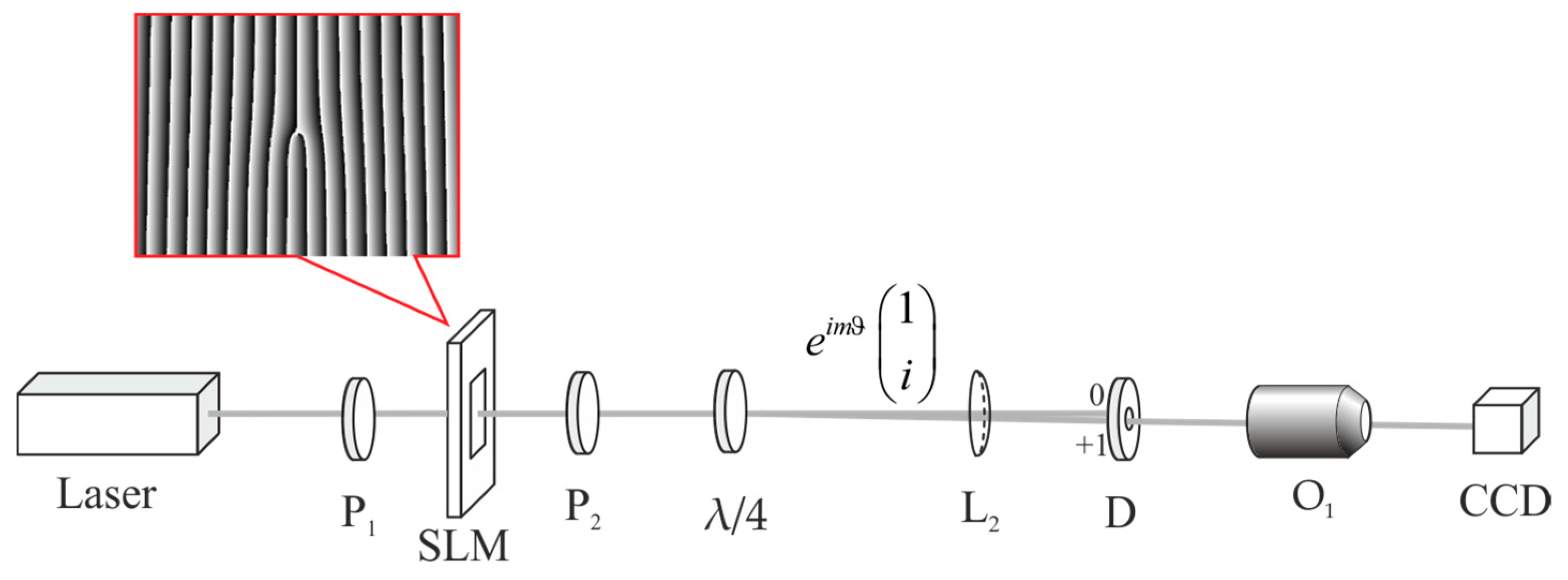
Figure 1. Optical scheme: laser with a wavelength of 633 nm; P1, P2 are polarizers; SLM is liquid crystal light modulator; λ/4 is quarter-wave plate; L2 is spherical lens; D is aperture: O1 is microobjective with a numerical aperture NA = 0.95; CCD is camera. The phase distribution in the form of a grating with a fork (shown in the inset) is generated in the modulator window. The formula after the quarter-wave plate describes the transverse components of the field (1).
Applsci 13 08361 g001
Figure 2. The distribution of intensity I (a) and its components Ix (b), Iy (c), Iz (d) in the focus of the beam with circular polarization (without vortex) for NA = 0.95.
Applsci 13 08361 g002
Figure 3. The patterns of the SAM components Sx (a), Sy (b), Sz (c) in the focus of the beam with circular polarization (without vortex) for NA = 0.95.
Applsci 13 08361 g003
Figure 4. The distribution of intensity I (a) and its components Ix (b), Iy (c), Iz (d) in the focus of the optical vortex with unit topological charge and with circular polarization for NA = 0.95.
Applsci 13 08361 g004
Figure 5. The patterns of the SAM components Sx (a), Sy (b), Sz (c) in the focus of optical vortex with unit topological charge and with circular polarization for NA = 0.95.
Applsci 13 08361 g005
Figure 6. The ratio S ^ z / L ^ z in the focus of light field (1) at different numerical apertures of the focusing lens for beams (1) with different topological charges: m = 0 (without vortex, blue line 1), m = 1 (red line 2), m = −1 (yellow line 3). The vertical dotted line drawn through the NA = 0.87.
Applsci 13 08361 g006
Disclaimer/Publisher’s Note: The statements, opinions and data contained in all publications are solely those of the individual author(s) and contributor(s) and not of MDPI and/or the editor(s). MDPI and/or the editor(s) disclaim responsibility for any injury to people or property resulting from any ideas, methods, instructions or products referred to in the content.