Article

Springback Prediction of Free Bending Based on Experimental Method

College of Mechanical and Electrical Engineering, Hohai University, Changzhou 213002, China
*
Author to whom correspondence should be addressed.
Appl. Sci. 2023, 13(14), 8288; https://doi.org/10.3390/app13148288
Submission received: 23 June 2023 / Revised: 11 July 2023 / Accepted: 13 July 2023 / Published: 18 July 2023

Abstract

:
The springback phenomenon has an impact on tube-processing quality during the free-bending process. For different pipe benders, the forming process is affected by different factors, such as gaps between the tube and the bending die and friction between the tube and the guiding mechanism and the bending die; thus, the theoretical U-R relationship cannot complete the precise processing required. In order to overcome the influence of springback during the free-bending forming process, a U-R experiment was performed first, and the actual U-R relationship was established. The U-R experiment demonstrated that when the bending die offset U increased, the tube-bending radius R decreased. Then, based on the results of the springback experiments, a springback prediction method was presented. The experimental method successfully predicted springback, demonstrating that the springback problem can be effectively solved through compensation of the arc section.

1. Introduction

Bending components are widely used in construction, manufacturing and aerospace applications [1,2,3,4]. With the continuous development of science and technology, the tube-bending process is facing more and more requirements. Traditional bending methods include press bending, stretch bending and so on [5,6], The above methods require the use of mold made according to each method’s profile. Therefore, these methods are difficult to apply in small batch productions. In order to solve this problem, free-bending technology was proposed. It was invented by Japanese scientists Makoto Murata, Shinji Ohashi and Hideo Suzuki. Originally, its name was composed of the initials of the three surnames, and was called MOS bending [7]. This technology can meet the requirements of bending tubes with different radii without changing the die [8]. In recent years, more and more researchers have conducted research on free-bending technology [8,9,10,11,12,13] based on many methods. Ali et al. [14] described in detail the theoretical development and technical status of free-bending technology in recent years and discussed its importance in tube forming. Cheng et al. [15] studied the influence of the mandrel on the forming quality of thin-walled tubes in free-bending forming, and optimized and determined the structure, size and installation position of the mandrel. Guo et al. [16] studied the effect of the bending die offset U on the forming radius R, which is a key factor in accurate tube construction. Cheng et al. [17] studied and analyzed tube formability under different wall thicknesses, and the results showed that when the relative wall thickness was 0.133, the ellipticity of the tube was the smallest, and a better forming quality could be obtained.
At present, most of the research on free-bending technology focuses on forming accuracy and forming quality, among which forming accuracy is the focus of scholars’ research. When the external load is unloaded, the stress in the tube returns to equilibrium, and the formed tube is different from the ideal shape. The springback phenomenon directly affects the final shape and forming quality of the forming parts. Therefore, it is necessary to study the springback phenomenon and find a solution. Many scholars have analyzed the springback phenomenon at the theoretical level, Wang et al. [18] studied the influence of different A values on the springback phenomenon through finite element analysis. The larger the A value is, the more obvious the springback phenomenon is. Li et al. [19], taking the AL6061 tube as a research object, predicted the springback based on finite element analysis, and enhanced the springback prediction model by considering the offset of the neutral layer. Megharbel et al. [20] provided a method to quantitatively predict springback based on the constitutive equation and obtained a more accurate springback calculation model. Zhang et al. [21] proposed a springback prediction model for variable curvature tubes based on the theoretical formula for springback angle prediction of fixed curvature tubes, which has good performance in solving the springback phenomenon of variable curvature tubes. Shi et al. [22] studied and solved the springback compensation problem through finite element numerical simulation and experimental verification. The results showed that the wall thickness and bending radius of the test tube had an important impact on the springback. With an increase in wall thickness, the amount of springback compensation decreased rapidly, and then showed a gentle trend. Razali et al. [23] proposed a springback prediction method for an accurate, fully implicit elasto-plastic finite element analysis function and multi-body processing scheme based on a tetrahedral micro-mesh system, which had an average error rate and maximum error rate of 8.1% and 12.4%, respectively. Wang et al. [24] proposed a numerical approximate springback prediction and compensation method by considering the section distortion of a spatially variable curvature tube, establishing the curvature and torsion mapping functions of the central axis of the tube before and after springback. After springback compensation, the position deviation of each node was less than 1.4%, and the average position deviation was 0.80%. Zhou et al. [25] considered the interference of section deformation, established the mapping relationship between characteristic parameters and cross-section distortion, and predicted the springback angle. The experimental results showed that the average error of the springback angle of this method was 4.73%, and the three different analytical models were 38.92%, 14.39% and 14.22% respectively. This method significantly improved the prediction accuracy of the springback angle.
To sum up, many scholars predicted the springback of free bending based on complex finite element and numerical analyses. Although these studies can predict springback well, they ignore the complexity of the influencing factors during the process of free bending, such as the gap between the bending die and the tube; the friction between the guide mechanism and the tube; the friction between the bending die and the spherical bearing; the bearing flutter; and the installation error of the bending machine, etc. Moreover, different materials have different U-R relationships, and the analysis and calculation of a single material is often not applicable to other materials. Therefore, an experimental method is proposed in this paper to avoid complex numerical calculations, as experimental data are the most real data. U-R experiments were carried out for Q235 carbon steel and aluminum 6061 to obtain the real U-R curve. U-R experiments showed that the radius R decreases with the increase of bending mode offset U, and different materials have different U-R relations. The springback experiment was carried out according to the real U-R data. Through the compensation of the transition section and the arc section, it was found that the compensation of the arc section can solve the springback phenomenon. A springback compensation curve capable of accurately predicting the springback was established.

2. Free-Bending Technology

Free-bending technology is different from traditional bending technologies such as winding, rolling and pressing. It is characterized by dieless bending, as there is no need to change the die to accommodate tubes with different bending radii. The tube bender adjusts the bending die pose in real time so as to realize the forming of tubes with different bending radii.
As shown in Figure 1, U is the offset of the bending die, which is the height of the center of the bending die from the axis of the guide mechanism in the plane formed by the bending tube. The distance between the center of the bending die and the foremost end of the guide mechanism is called A. The length of the arc segment formed during the movement of the bending die from 0 to U is called ‘l’. With the bending die tangent to the spherical bearing, the spherical bearing installed on the bearing seat is driven by the motor to move in the plane XOY perpendicular to the feeding direction of the Z axis. The bending die is assumed to be at the origin. Before processing, the bending die is set in the original position, and its axis coincides with the axis of the guide mechanism, which is called the equilibrium position. During processing, the spherical bearing is pushed by a servomotor which drives the bending die to move in the XOY plane from the equilibrium position to the processing position U. The tube blank deforms under the combined action of the force applied by the inner wall of the bending die and the propulsion force to form an arc-shaped tube with a bending radius R and an axis arc length l. After the tube with the predetermined arc length is formed, the bending die moves to the next processing position or returns to the equilibrium position. Conversely, the straight section is processed when the bending die is kept at the initial equilibrium position.
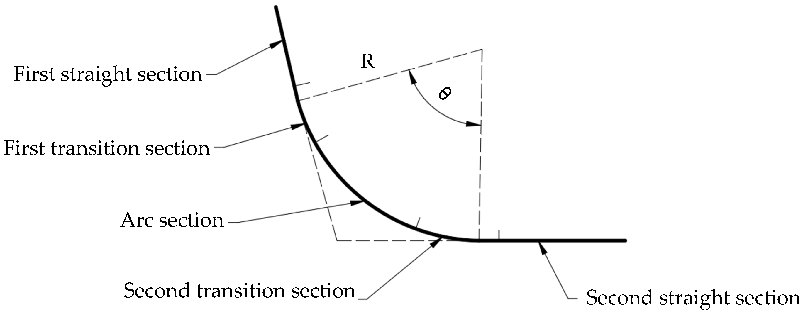
As shown in Figure 2, there are five stages of a single bend: the first straight section, first transition section, arc section, second transition section, and second straight line.
(1)
First transition section
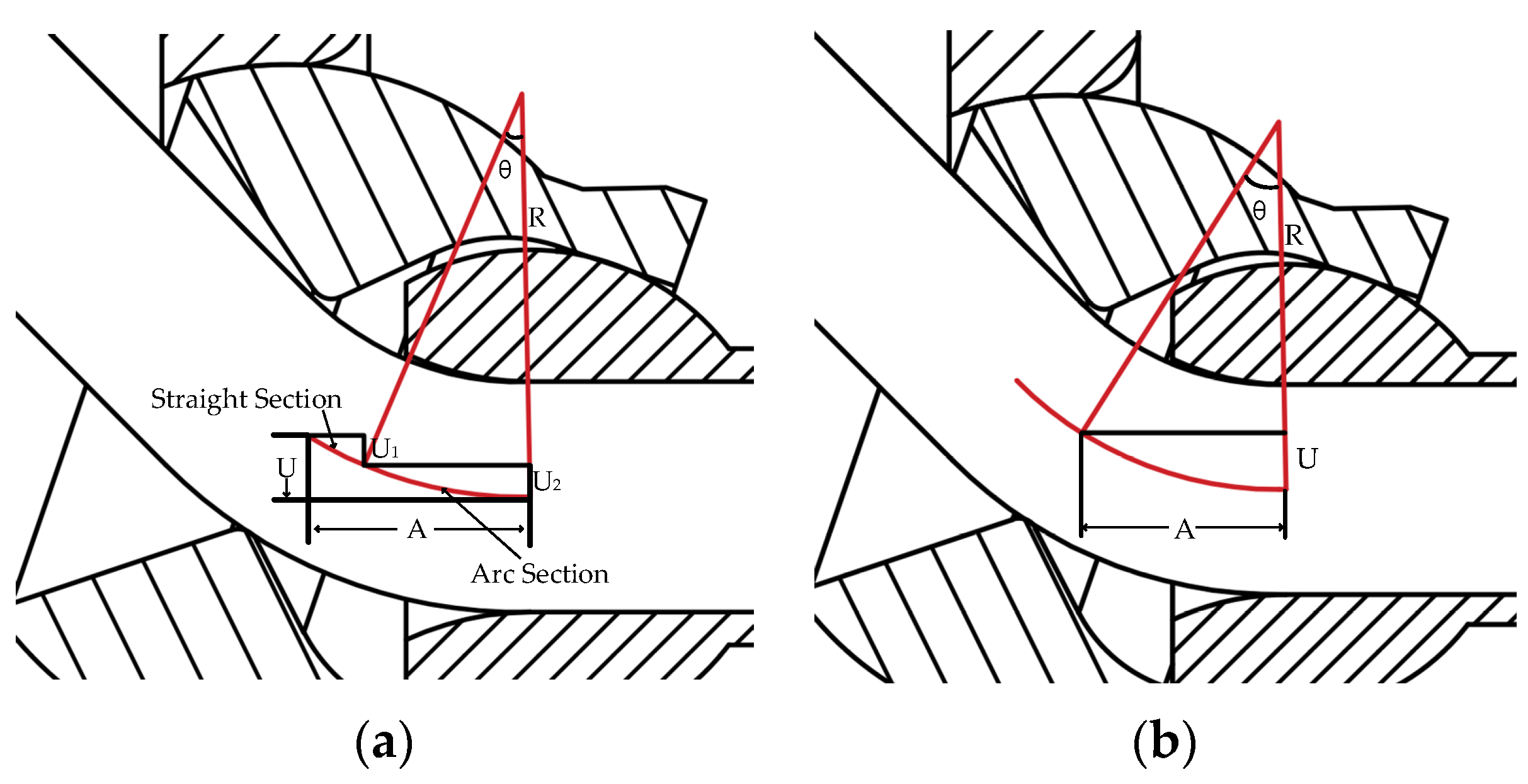
Figure 3a shows the first transition section of the bending die movement to U. During the first transition section, the tube is in a state of dynamic combination and transition from a straight line and an arc section. At the moment the bending die starts to move, the tube within the guide distance A are straight segments, and the arc section is firstly generated at the outlet of the guide mechanism and gradually spreads to the whole guide distance along with the uniform delivery of the tube blank. The straight section within the guide distance becomes shorter and shorter during the feeding movement, and the radius of the arc section decreases from infinity to the target radius.
Set the feeding time as t 1 , the real-time sending length is v Z t 1 , the bending die offset U 1 of straight section, the bending die offset U 2 of arc section is can be obtained using Equations (1) and (2):
U 1 = tan 180 v Z t 1 π R × A R sin 180 v Z t 1 π R
U 2 = R 1 cos 180 v Z t 1 π R
The total bending die offset U is the sum of U 1 and U 2 , its value is in dynamic change. The relationship between U, radius R and feeding time t 1 can be calculated by Equation (3):
U = U 1 + U 2 = R R cos 180 v Z t 1 π R + tan 180 v Z t 1 π R A R sin 180 v Z t 1 π R
The total length L 1 of the tube blank in the first transition section can be calculated by Equation (4):
L 1 = π R arcsin A R 180 °
(2)
Arc section
In the arc section, the bending die reaches the predetermined U and holds on. The tube blank is continuously sent out by the feeding mechanism, and an arc section with bending radius R is generated within the guide distance. The U of the arc section and feeding length L 2 can be calculated by Equations (5) and (6):
U = R R 2 A 2
L 2 = π θ R 180 ° π R arcsin A R 180 °
(3)
Second transition section
Figure 3b shows the second transition section of the bending die from U back to the initial equilibrium position. In the second transition section, the center of the bending die returns to the equilibrium position at a uniform speed from the processing position. Similar to the first transition section, the tube is in a state of dynamic combination and transition from a straight line and an arc section, the straight section is first generated at the outlet of the guide mechanism and gradually spreads to the whole guide distance. At the same time, the bending radius of the newly generated arc section gradually increases to infinity until the bending die reaches the equilibrium position, and the tube section sent out from the bending die is completely a straight section. The feeding length L 3 in second transition section can be calculated by Equation (7):
L 3 = A
Set the feeding time of this section as t 3 , the feeding distance at time t 3 is v z t 3 . The relationship between the offset U of the bending die, the bending radius R and the feeding time t 3 can be calculated by Equation (8):
U = R R cos θ = R R 1 A v Z t 3 R 2
To sum up, the value of the U is related to the tube bending radius R, the guide distance A and the feeding length L. The guide distance A in the bending die follow-up tube bender is a fixed mechanical distance, and the corresponding bending radius R can be formed by adjusting U for a circular arc tube with the arc length L. Therefore, the relationship between U and R is defined as a U-R relationship. Establishing a reasonable and accurate U-R relationship is the key to ensure the forming accuracy of free bending.
In the free-bending process, these factors, such as the gap between the bending die and the tube, the friction between the tube and the guide mechanism, the friction between the bending die and the spherical bearing and so on, which will affect the accuracy of the U-R relationship, and different materials have different U-R relationship during the process. The U-R experiment was carried out, considering the influence of these factors.

3. Experimental Verification

Different tube benders have a variety of processing errors due to installation errors, the bending die clearance, bearing flutter, misalignment of die installation, non-horizontal installation, and so on. The final forming is affected by many factors, such that the theoretical relationship may not meet the processing requirements. According to results obtained in the experiment, the transition section and the arc section were analyzed, respectively, and the general experimental springback law was obtained. Before the springback experiment, the key U-R relationship model should be obtained according to the experiment.

3.1. U-R Experiment

U-R experiments were carried out on carbon steel Q235 and aluminum 6061. The uniform tube diameter was 32 mm, the tube wall thickness was 2 mm, and the feeding speed was 10 mm/s. The U-R experimental data are shown in Table 1 and Table 2. The experimental data were fitted separately to obtain the U-R general curve, as shown in Figure 4a,b.
According to the curve obtained by fitting, the mapping relationship between U and R was obtained and the U-R database was established. As can be seen from the curves above, when the bending die offset U increases, the tube bending radius R decreases. This rule was found in both U-R experiments. As we all know, carbon steel Q235 has better toughness than aluminum 6061. The carbon steel tube has a larger springback when the U value transits from 2 to 2.5, so when we carried out the U-R experiment of aluminum, we narrowed the interval to observe the springback phenomenon of aluminum with lower toughness in the free-bending process. In fact, the material still adhered the rule that R decreases as U increases, but the degree of springback varies according to the material. Next, the springback analysis was performed on the transition and bend sections based on the U-R database.

3.2. Springback Experiment

According to the experimental U-R relationship, the corresponding bending angle can be obtained, and the single bending experiment was carried out according to the theoretical bending angle and springback bending angle. A Q235 carbon steel tube with a diameter of 32 mm and a wall thickness of 2 mm was used as the tube blank. Because the forming process is influenced by the value of U, the processing process was divided into five stages: first straight section, first transition section, arc section, second transition section, and second straight section. Because the springback phenomenon does not occur in the straight section, only the springback phenomena of the first transition section, the bending section and the second transition section were considered. First, single bends were processed to observe the stress and strain phenomena of the cross-section of the bending section. The experiment showed that the actual arc length was shorter than the theoretical arc length. In the process of tube bending formation, the conventional distribution of the wall thickness took the neutral layer as the boundary, and the outer wall of the tube was thinned while the inner wall was thickened. In the free-bending process, under the action of the axial thrust force and the bending moment of the bending die, the strain neutral layer of the tube deviated like the outer side of an arc, and in this process, the inner side led to the thinning of the outer arc wall of the tube and the accumulation of the inner arc wall. As shown in Figure 5, it can be clearly seen that the inner side of the arc is thickened, and the outer side of the arc is thinned. This is due to the fact that the neutral layer deviates to the outside of the arc during free bending [26]. Excessive accumulation in the inner side leads to the reduction of extrusion of the arc segment, which is also the reason why the experimental arc segment is smaller than the theoretical arc segment in the actual measurement process.
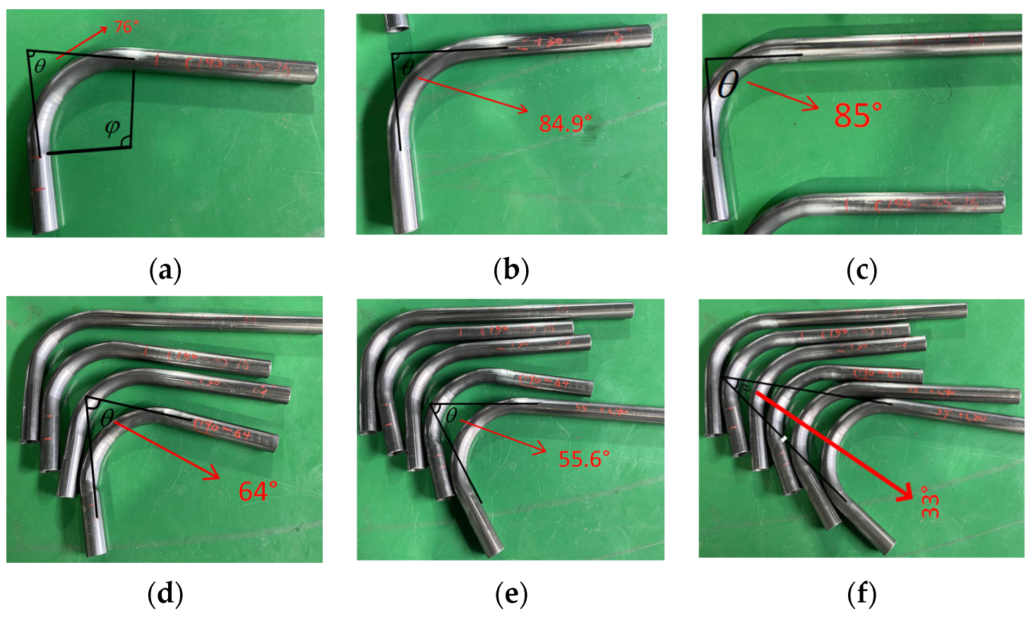
Through measurements, it can be seen that the actual arc length is shorter than the theoretical arc length, so the compensation experiment was considered for the transition section and arc section. First, a single bend experiment with a single bend angle of 45° was carried out. The tube was processed according to the theoretical value, and the formed tube is shown in Figure 6a.
After the original tube is formed without any treatment, the actual included angle is 76°, and the springback angle α can be calculated by Equation (9):
α = θ 1 θ 0
It can be seen that the initial springback angle without treatment is 31°, and the error is large. Next, the compensation experiment is carried out for each segment.
(1)
Compensate the first transition section
The first transition section is compensated by 30 mm, as shown in Figure 6b. At this time, the angle increases from 76° to 84.9°;
(2)
Compensate the second transition section
The second transition section is compensated by 30 mm, as shown in Figure 6c. At this time, the angle increases from 76° to 85°.
It can be seen that the springback angle does not decrease but increases after compensating the transition section, so the experiment continues to control the variable and only compensates the arc section;
(3)
Compensate the arc segment
The arc section is modified. On the basis of the original processing data, the first transition section is reduced by 20 mm, the second transition section is reduced by 20 mm, and the arc break compensation is 40 mm. The formed tube is shown in Figure 6d. At this time, the included angle is reduced from 76° to 64°.
It can be seen that the compensation of the arc section can achieve the purpose of reducing the springback. Next, continue to compensate the arc section. The arc section compensation is 40 mm while the straight and transition section compensation is −40 mm, and the formed tube is as shown in Figure 6e. At this time, the included angle is reduced from 76° to 55.6°.
Continue to compensate the arc section for 80 mm, and the included angle is 33°, as shown in Figure 6f.
Figure 6. Diagram of included angle 45 experiment: (a) original state of included angle 45; (b) compensating first transition section; (c) compensating second transition section; (d) reduced transition section and compensation arc section; (e) 40 mm arc segment compensation; and (f) 80 mm arc segment compensation.
Applsci 13 08288 g006
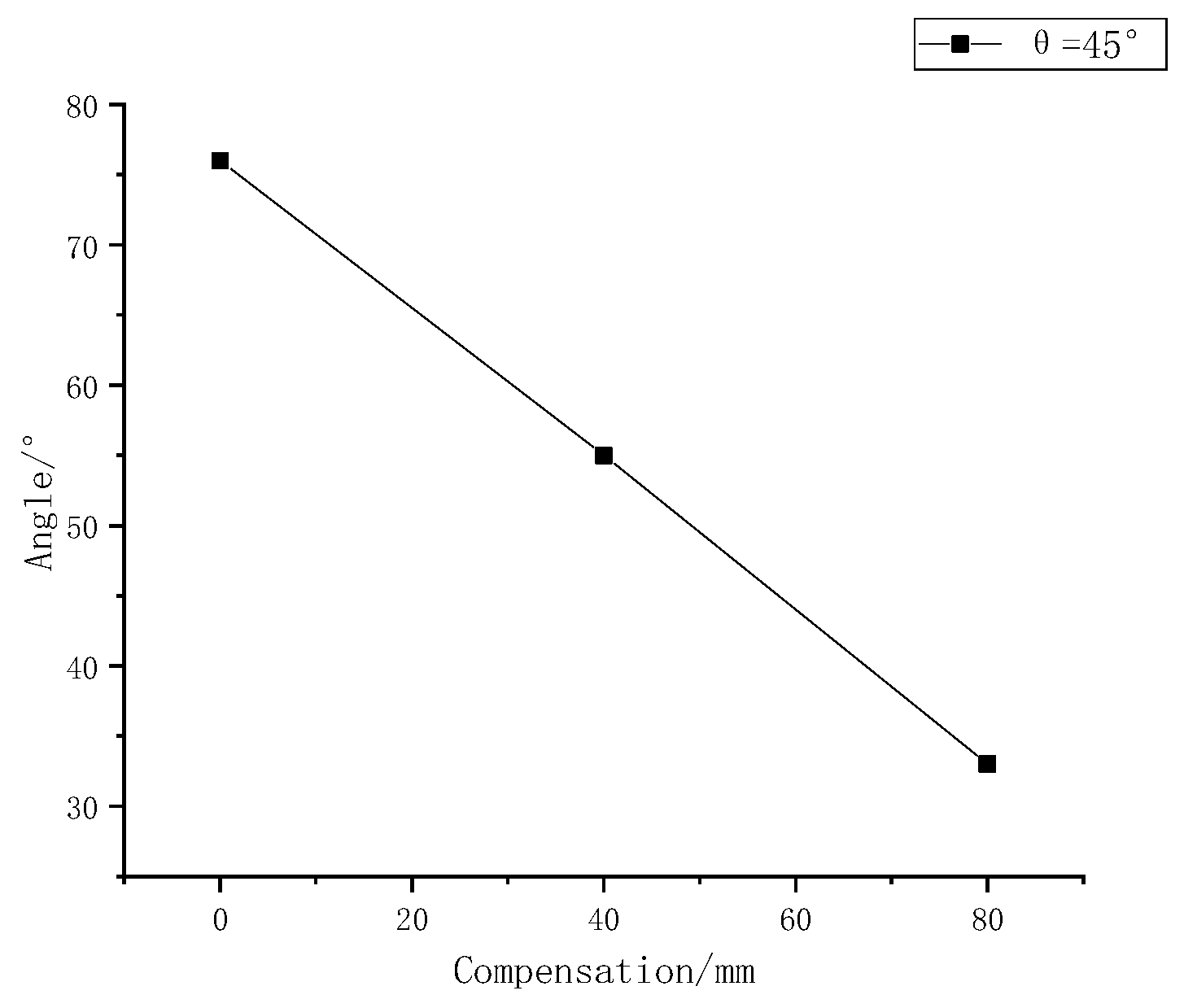
Based on the experiments above, it was found that the larger the compensation distance is, the smaller the springback angle is, and the less obvious the springback phenomenon is. Based on the fitting of the springback compensation and the corresponding angle, it was found that there is a linear relationship between the compensation value and the angle, as shown in Figure 7. This linear equation is:
C = 1 . 86 θ + 141 . 7
where C is the compensation value and θ is the included angle.
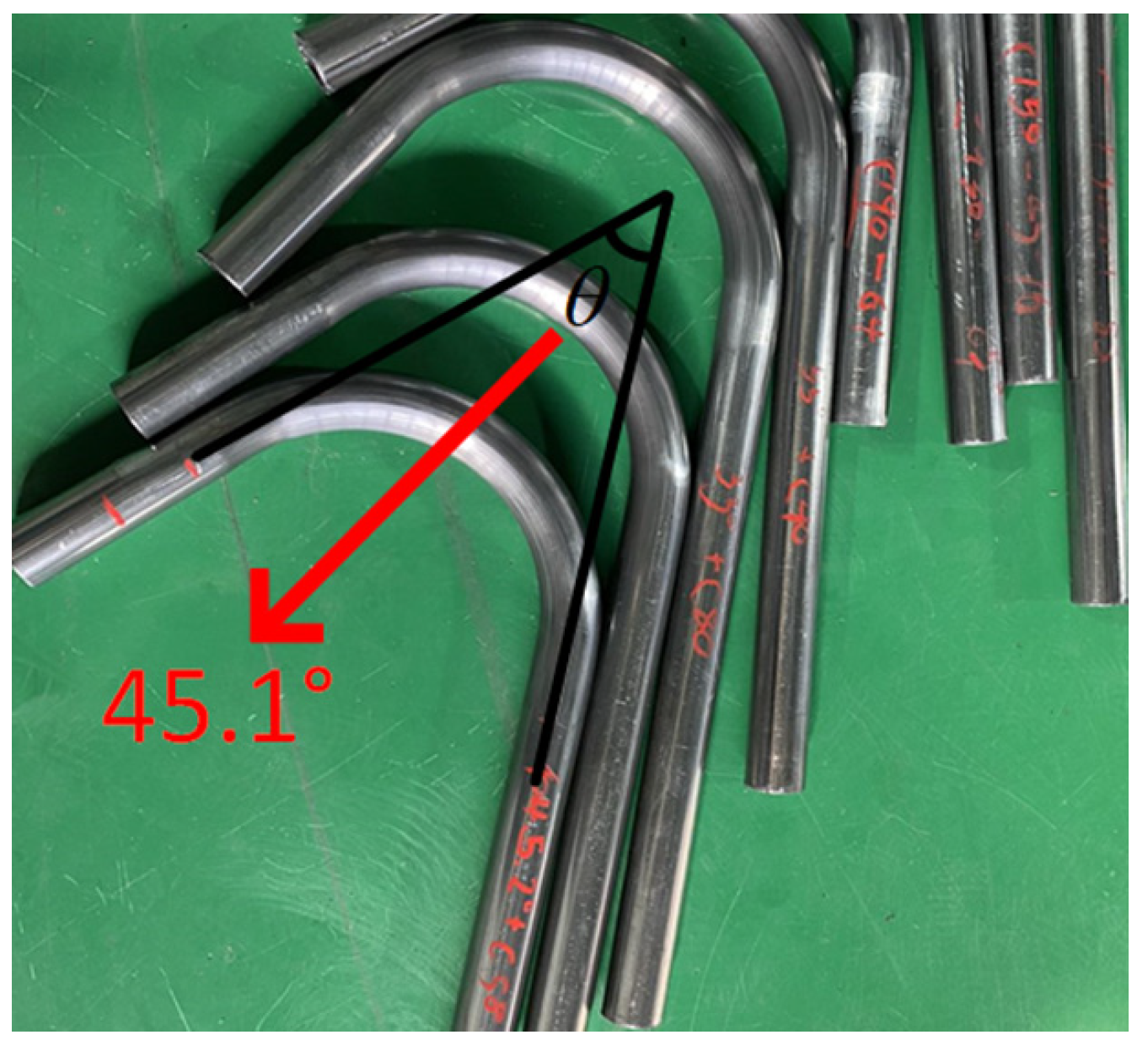
According to the compensation-included angle curve, when the theoretical included angle is 45°, that is, the central angle is 135°, the compensation value can be calculated according to the equation, and the calculated compensation value is 58 mm. At this time, the compensation value is substituted into the processing, and the included angle after forming is 45.1°, as shown in Figure 8. Therefore, the method is feasible.
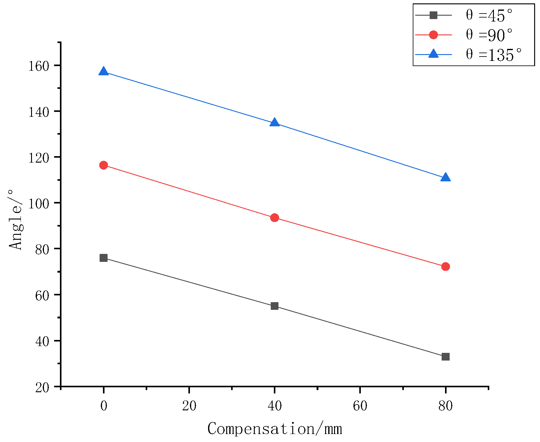
According to this method, only two groups of compensation data are needed to verify the springback compensation of angle 90° and angle 135°. The validation results are shown in Table 3. The compensation versus springback curve is shown in Figure 9.
From the function obtained in the above table, the springback value of the tube with an included angle of 90° and an included angle of 135° can be obtained, and the experimental results are shown in Figure 10 and Figure 11.
According to the springback law obtained from the experiment, the double-bending experiment with an angle of 90° was verified, and the results are shown in Figure 12.

4. Conclusions

In this paper, the springback prediction of free bending was studied, which provided a springback prediction method for tube bending. A compensation method for the transition section and the arc section was proposed which can ultimately achieve the purpose of springback prediction. The conclusions are as follows:
(1)
The theoretical U-R relationship cannot meet the actual processing requirements, and the actual processing is affected by many factors. The experimental U-R data show that the larger the bending die offset U is, the smaller the bending radius R is. Different materials have different U-R relationships;
(2)
From the cross-section, it can be seen that in the process of free bending, the material outside the arc is thinner, and the material inside the arc is thicker. This will cause the tube to be squeezed and stretched unnecessarily during the actual process. However, the length of the arc section of the actual bent pipe is shorter than the length of the theoretical arc section, which also verifies this point;
(3)
Compensating the transition section cannot solve the springback problem, while compensating the arc section can solve the springback problem well. The springback angle, with a small error, can be obtained using the experimental method. The general rule of the springback of the tube can be obtained by the springback compensation experiment: with the increase of the compensation value, the included angle is smaller. An ideal tube can be obtained according to that rule.

Author Contributions

Conceptualization, M.H. and W.Z.; methodology, M.H. and W.Z.; validation, M.H. and W.Z.; formal analysis, M.H. and W.Z.; investigation, M.H. and W.Z.; resources, M.H. and W.Z.; data curation, M.H. and W.Z.; writing—original draft preparation, M.H. and W.Z.; writing—review and editing, M.H. and W.Z.; visualization, M.H. and W.Z.; supervision, M.H. and W.Z.; project administration, W.Z.; funding acquisition, W.Z. All authors have read and agreed to the published version of the manuscript.

Funding

This research was funded by National Natural Science Foundation of China, grant number 52179129.

Institutional Review Board Statement

Not applicable.

Informed Consent Statement

Not applicable.

Data Availability Statement

Not applicable.

Conflicts of Interest

The authors declare no conflict of interest.

References

  1. Zhang, Z.; Wu, J.; Liang, B.; Wang, M.; Yang, J.; Muzamil, M. A new strategy for acquiring the forming parameters of a complex spatial tube product in free bending technology. J. Mater. Process Technol. 2020, 282, 116662. [Google Scholar] [CrossRef]
  2. Zhang, Z.; Wu, J.; Shang, Q.; Jiang, Q.; Yang, J.; Guo, R. A new strategy for describing the characteristics of bending line in flexible push bending. Eng. Comput. 2019, 36, 1597–1607. [Google Scholar] [CrossRef]
  3. Al-Qureshi, H. Elastic-plastic analysis of tube bending. Int. J. Mach. Tool. Manuf. 1999, 39, 87–104. [Google Scholar] [CrossRef]
  4. Yang, H.; Li, H.; Zhang, Z.; Zhan, M.; Liu, J.; Li, G. Advances and Trends on Pipe Bending Forming Technologies. Chin. J. Aeronaut. 2012, 25, 1–12. [Google Scholar] [CrossRef] [Green Version]
  5. Fang, J.; Liang, C.; Lu, S.; Wang, K. Effect of geometrical parameters on forming quality of high-strength TA18 titanium alloy pipe in numerical control bending. Trans. Nonferrous Met. Soc. China 2017, 28, 309–318. [Google Scholar] [CrossRef]
  6. Murata, M.; Kuboki, T. CNC Pipe Forming Method for Manufacturing Flexibly and 3-Dimensionally Bent Pipes. In 60 Excellent Inventions in Metal Forming; Springer: Berlin/Heidelberg, Germany, 2015; Volume 820, pp. 363–368. [Google Scholar]
  7. Murata, M.; Ohashi, N.; Suzuki, H. New flexible penetration bending of a pipe:1st report, a study of MOS bending method. Trans. Jpn. Soc. Mech. Eng. 1989, 55, 2488–2492. [Google Scholar] [CrossRef] [Green Version]
  8. Gantner, P.; Bauer, H.; Harrison, D.K.; De Silva, A.K. Free-bending—A new bending technique in the hydroforming process chain. J. Mater. Process. Technol. 2005, 167, 302–308. [Google Scholar] [CrossRef]
  9. Kawasumi, S.; Takeda, Y.; Matsuura, D. Precise pipe-bending by 3-RPSR parallel mechanism considering springback and clearances at dies. Trans. JSME 2014, 80, 820. [Google Scholar]
  10. Guo, X.; Wei, W.; Yong, X.; Ali, A.E.-A.; Hai, L.; Hui, W.; Xinyi, L.; Jie, T. Wall thickness distribution of Cu–Al bimetallic pipe based on free bending process. Int. J. Mech. Sci. 2019, 150, 12–19. [Google Scholar] [CrossRef]
  11. Guo, X.; Xiong, H.; Xu, Y.; Ma, Y.; El-Aty, A.A.; Tao, J.; Jin, K. Free-bending process characteristics and forming process design of copper tubular components. Int. J. Adv. Manuf. Tech. 2018, 96, 3585–3601. [Google Scholar] [CrossRef]
  12. Guo, X.; Ma, Y.; Chen, W.; Xiong, H.; Xu, Y.; El-Aty, A.A.; Jin, K. Simulation and experimental research of the free bending process of a spatial pipe. J. Mater. Process Tech. 2018, 255, 137–149. [Google Scholar] [CrossRef]
  13. Guo, X.; Xiong, H.; Li, H.; Xu, Y.; Ma, Z.; El-Aty, A.A.; Ma, Y.; Jin, K. Forming characteristics of pipe free-bending with small bending radii based on a new spherical connection. Int. J. Mach. Tool. Manuf. 2018, 133, 72–84. [Google Scholar] [CrossRef]
  14. El-Aty, A.A.; Guo, X.; Lee, M.-G.; Tao, J.; Hou, Y.; Hu, S.; Li, T.; Wu, C.; Yang, Q. A review on flexibility of free bending forming technology for manufacturing thin-walled complex-shaped metallic pipes. Int. J. Light. Mater. Manuf. 2023, 6, 165–188. [Google Scholar]
  15. Cheng, C.; Chen, H.; Guo, J.; Guo, X.; Shi, Y. Investigation on the influence of mandrel on the forming quality of thin-walled pipe during free bending process. J. Manuf. Process. 2021, 72, 215–226. [Google Scholar] [CrossRef]
  16. Guo, X.; Xiong, H.; Xu, Y.; El-Aty, A.A.; Ma, Y.; Zhao, Y.; Zhang, S. U-R relationship prediction method for aluminum alloy circular pipe free-bending process based on sensitivity analysis of material parameters. Int. J. Adv. Manuf. Technol. 2018, 99, 1967–1977. [Google Scholar] [CrossRef]
  17. Cheng, X.; Guo, X.; Tao, J.; Xu, Y.; El-Aty, A.A.; Liu, H. Investigation of the effect of relative thickness (t/d) on the formability of the AA6061 pipes during free bending process. Int. J. Mech. Sci. 2019, 160, 103–113. [Google Scholar] [CrossRef]
  18. Wang, W.; Hu, S.; El-Aty, A.A.; Wu, C.; Yang, Q.; Chen, H.; Shen, Y.; Tao, J. Springback analysis of different A-values of Cu and Al pipes in free bending forming technology: Experimentation and finite element modeling. Int. J. Adv. Manuf. Tech. 2021, 113, 705–719. [Google Scholar] [CrossRef]
  19. Li, Y.; Li, A.; Yue, Z.; Qiu, L.; Badreddine, H.; Gao, J.; Wang, Y. Springback prediction of AL6061 pipe in free bending process based on finite element and analytic methods. Int. J. Adv. Manuf. Tech. 2020, 109, 1789–1799. [Google Scholar] [CrossRef]
  20. El Megharbel, A.; El Nasser, G.A.; El Domiaty, A. Bending of pipe and section made of strain-hardening materials. J. Mater. Process Tech. 2008, 203, 372–380. [Google Scholar] [CrossRef]
  21. Zhang, S.; Fu, M.; Wang, Z.; Fang, D.; Lin, W. Springback prediction model and its compensation method for the variable curvature metal pipe bending forming. Int. J. Adv. Manuf. Tech. 2021, 112, 3151–3165. [Google Scholar] [CrossRef]
  22. Shi, C.; Fu, W.; Li, M.; Yi, Z. Springback Analysis in Flexible-bending Process of Pipes. Mater. Sci. Eng. 2019, 540, 012012. [Google Scholar]
  23. Razali, N.A.; Chung, S.H.; Chung, W.J.; Joun, M.S. Implicit elastoplastic finite element analysis of pipe-bending with an emphasis on springback prediction. Int. J. Adv. Manuf. Tech. 2022, 120, 6377–6391. [Google Scholar] [CrossRef]
  24. Wang, Z.; Lin, Y.; Qiu, L.; Zhang, S.; Fang, D.; He, C.; Wang, L. Spatial variable curvature metallic pipe bending springback numerical approximation prediction and compensation method considering cross-section distortion defect. Int. J. Adv. Manuf. Technol. 2022, 118, 1811–1827. [Google Scholar] [CrossRef]
  25. Zhou, H.; Zhang, S.; Qiu, L.; Wang, Z. Springback angle prediction of circular metal pipe considering the interference of cross-sectional distortion in mandrel-less rotary draw bending. Sci. Progress. 2021, 104, 1–30. [Google Scholar] [CrossRef] [PubMed]
  26. Chen, H.; Wang, H.; El-Aty, A.A.; Qin, Y.; Li, J.; Zhang, Y.; Li, T.; Guo, X. Impact of bending dies with different friction forms on forming force and quality of pipes manufactured by free bending technology. Chin. J. Aeronaut. 2021, 34, 253–264. [Google Scholar] [CrossRef]
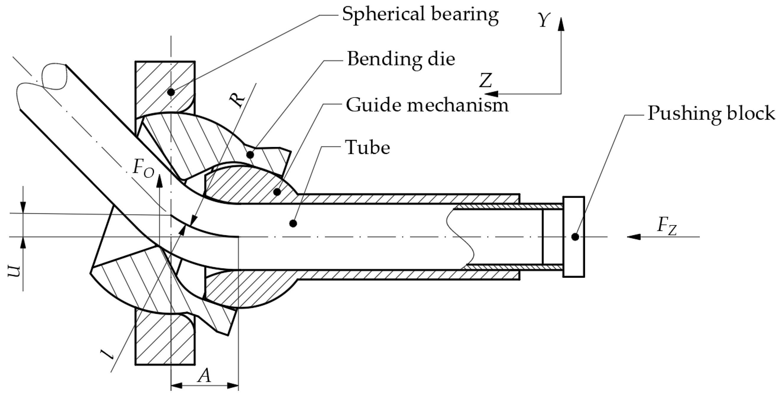
Figure 1. Diagram of free-bending structure.
Applsci 13 08288 g001
Figure 2. Diagram of the stages of free-bending.
Applsci 13 08288 g002
Figure 3. Diagram of the transition sections: (a) first transition section; and (b) second transition section.
Applsci 13 08288 g003
Figure 4. U-R curve: (a) Q235 U-R curve; and (b) Al6061 U-R curve.
Applsci 13 08288 g004
Figure 5. Tube Cross Section.
Applsci 13 08288 g005
Figure 7. Compensation-included angle curve 45°.
Applsci 13 08288 g007
Figure 8. Tube of 45° included angle.
Applsci 13 08288 g008
Figure 9. Compensation-included angle curve.
Applsci 13 08288 g009
Figure 10. Springback experiment with 90° included angle: (a) C0; (b) C40; (c) C80; and (d) C47.29.
Applsci 13 08288 g010
Figure 11. Springback experiment with 135° included angle: (a) C0; (b) C40; (c) C80; and (d) C38.515.
Applsci 13 08288 g011
Figure 12. Comparison before and after forming of double-bending 90° tube: (a) before treatment; and (b) after treatment.
Applsci 13 08288 g012
Table 1. Table of Q235 U-R Relationship Experimental Data.
U (mm)22.53461015
14998.161823.51167.2619.85312.8155.1197.32
25137.71892.71172.7624.5317.22155.1194.42
36096.11982.91255.2619.85315154.0394.83
44806.32047.91212.6621.39313.9161.8895.64
54097.21810.41172.7626.06321.77157.364.42
65317.71892.71161.8613.76319.48159.5696.23
75433.31982.91151.1613.76322.93158.4295.23
84715.61878.51178.2612.26319.48151.9294.83
95206.91892.71195.1612.26319.9156.1993.63
105680.41759.41200.9615.27319.48147.8893.23
Average5148.9361896.361186.75617.896318.196155.7491.978
Table 2. Table of Al6061 U-R Relationship Experimental Data.
U (mm)2.22.352.52.552.73.253.55
11771.21427.51207.61115.111015.3762.93635.61373.3
21734.91427.51207.61090.71012.9770.56627.63373.54
31747.11419.31210.31120.1989.7773.13629.21373.3
41878.51403.41199.61172.11005.5768627.63376.66
51797.41419.31200.31188.21000.3765.46626.06373.86
61734.91435.712031140.51021.3760.42637.23373.3
71734.91357.61198.51139.3997.3765.46627.23371.65
81771.91460.91196.71141.11110.1760.42630.8375.54
91771.91411.31201.71137.31005.4762.93632.39372.75
101759.41411.31201.71155.11002.3760.42622.94373.86
Average1770.211417.381202.71139.551015.81764.973629.673373.776
Table 3. Compensation-Included Angle.
Compensation (mm) θ = 90° θ = 135°
The Angle of the Actual Springback (°)
0116.4157
4093.5134.7
8072.2110.8
Functional relation C = 1.809 θ + 210.1 C = 1.731 θ + 272.2
Disclaimer/Publisher’s Note: The statements, opinions and data contained in all publications are solely those of the individual author(s) and contributor(s) and not of MDPI and/or the editor(s). MDPI and/or the editor(s) disclaim responsibility for any injury to people or property resulting from any ideas, methods, instructions or products referred to in the content.