
Research on Construction Sequences and Construction Methods of the Small Clear-Distance, Double-Arch Tunnel under an Asymmetrical Load


Abstract
1. Introduction
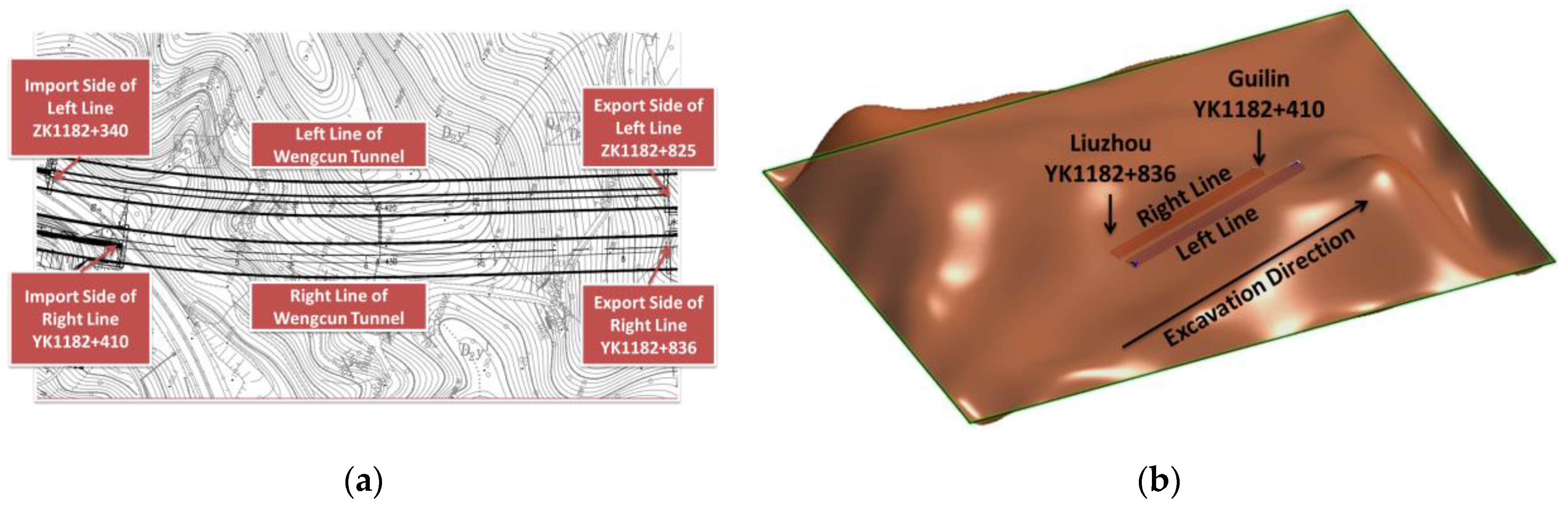
2. Project Overview
3. Numerical Model
3.1. Model Building
3.2. Model Parameters
3.3. Simulation Schemes
3.3.1. Simulation Scheme of Excavation Sequence
3.3.2. Simulation Scheme of Excavation Method
4. Results and Discussion
4.1. Analysis of Excavation Sequence
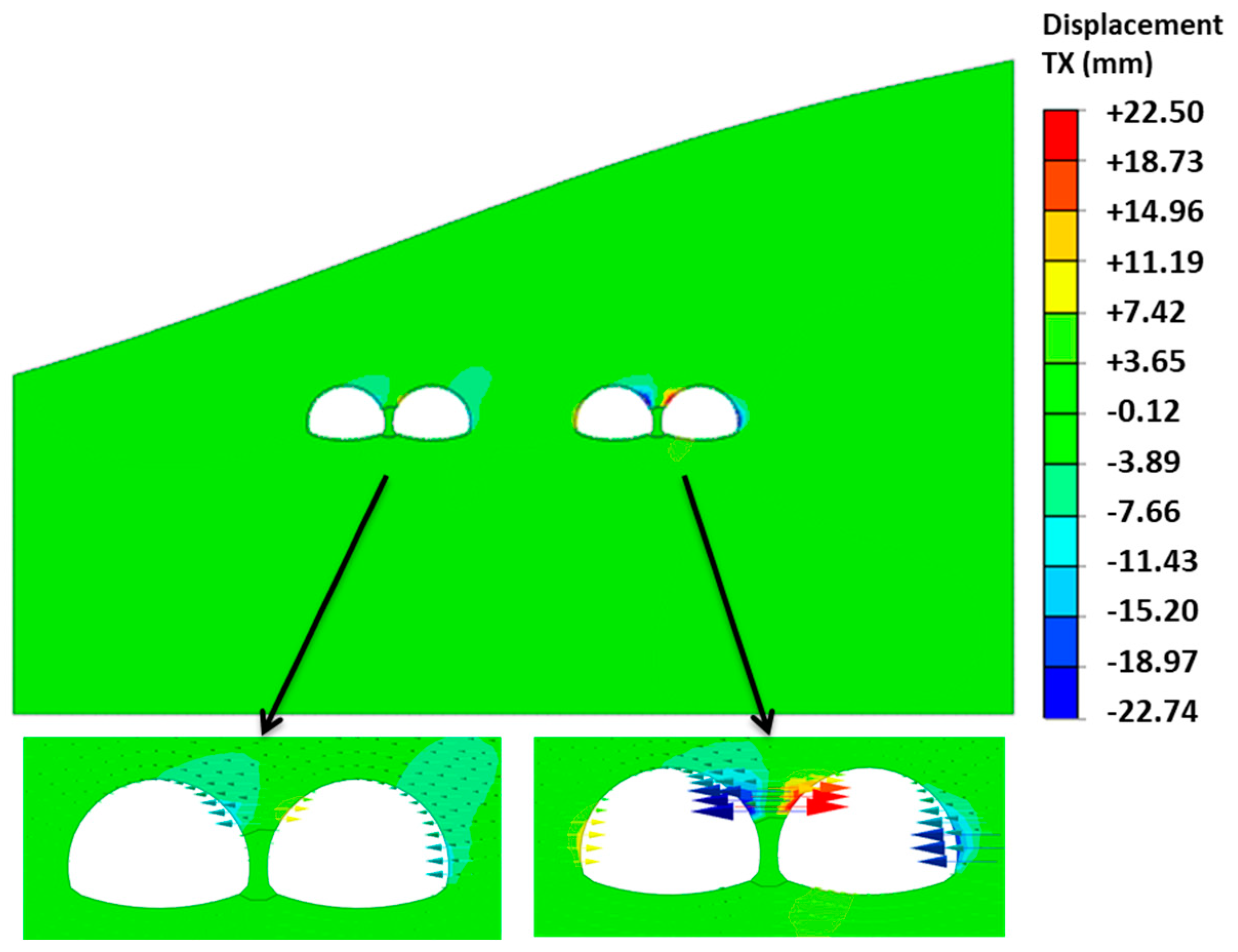
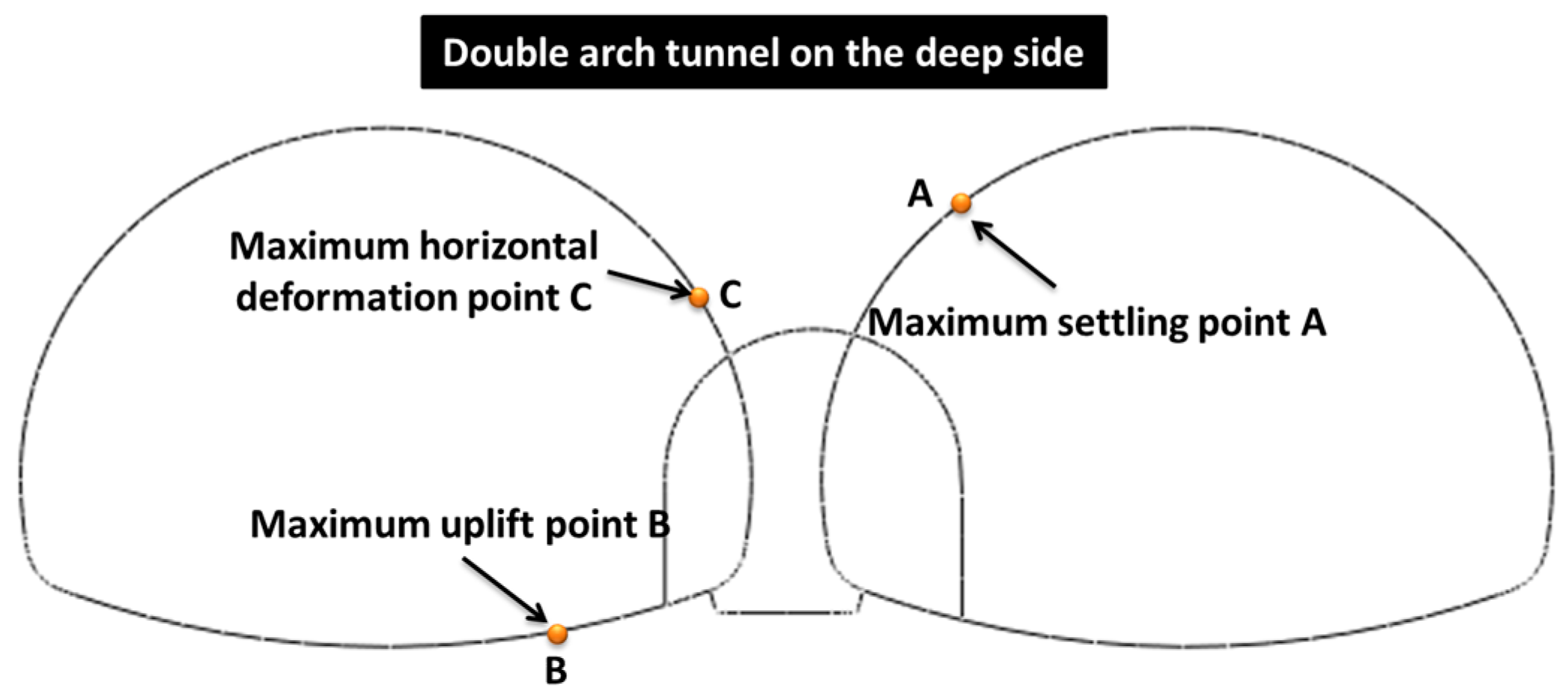
4.1.1. Deformation Analysis
- (1)
- Deformation analysis of the surrounding rock and tunnel
- (2)
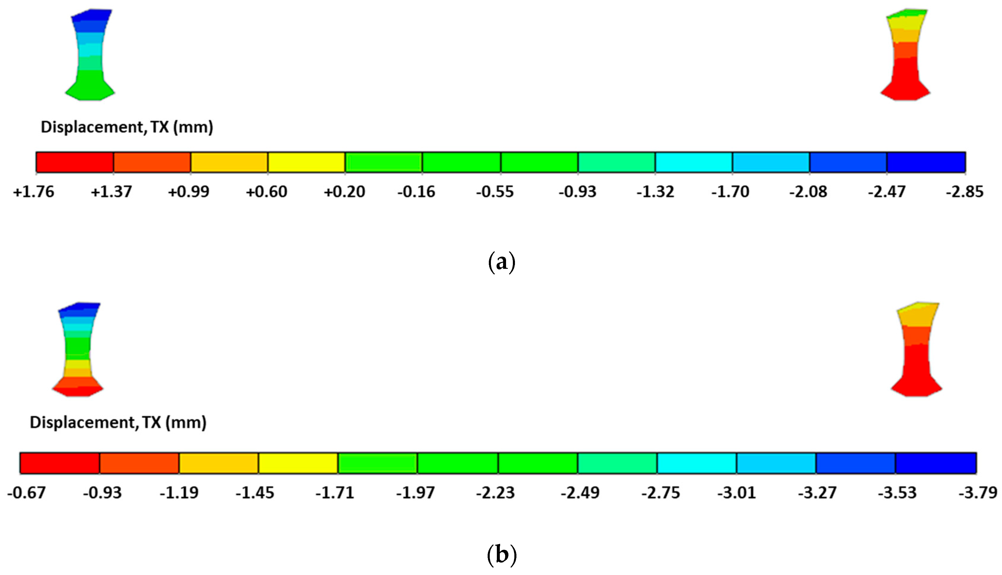
- Tipping analysis of the middle partition wall
4.1.2. Force Analysis
- (1)
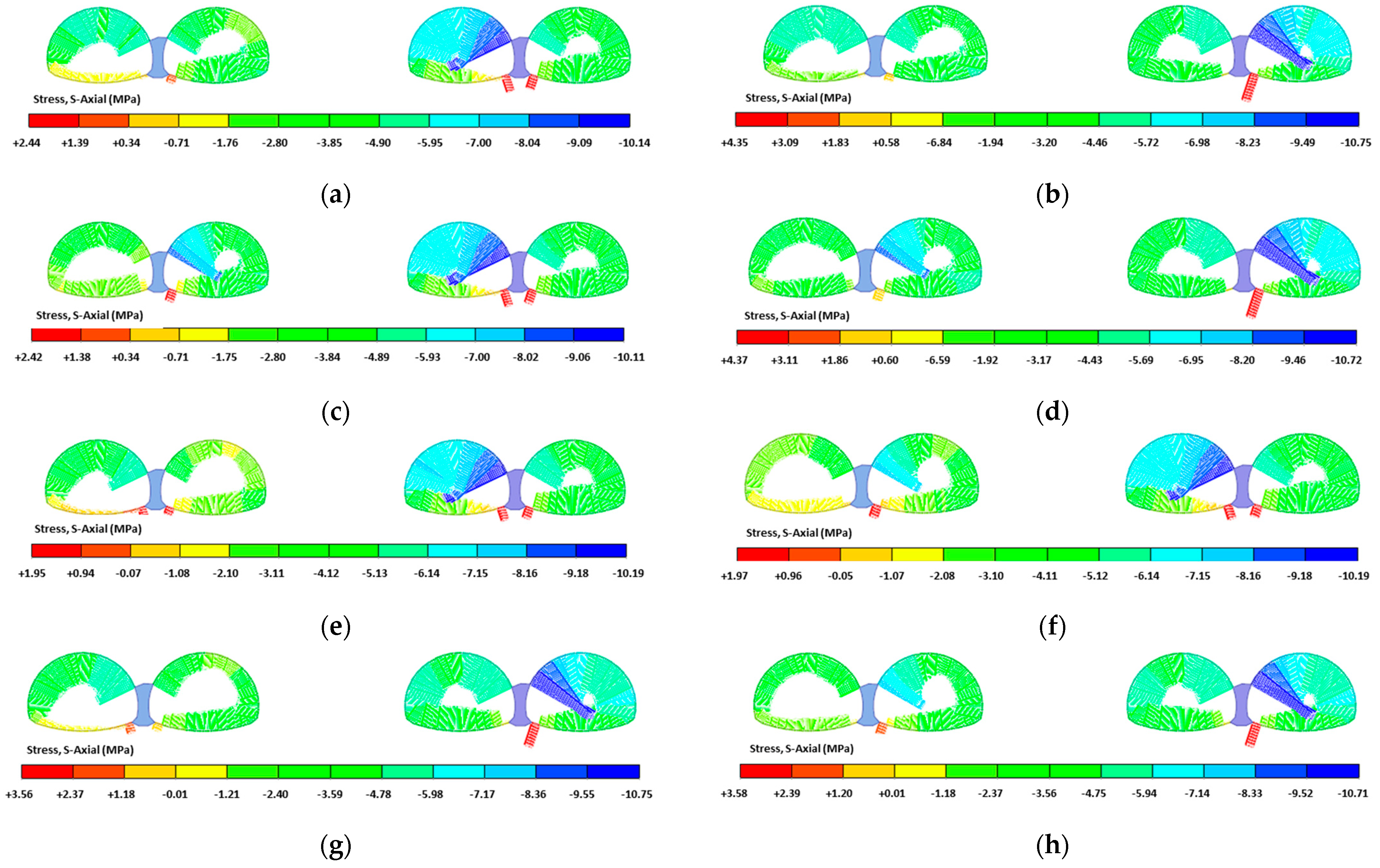
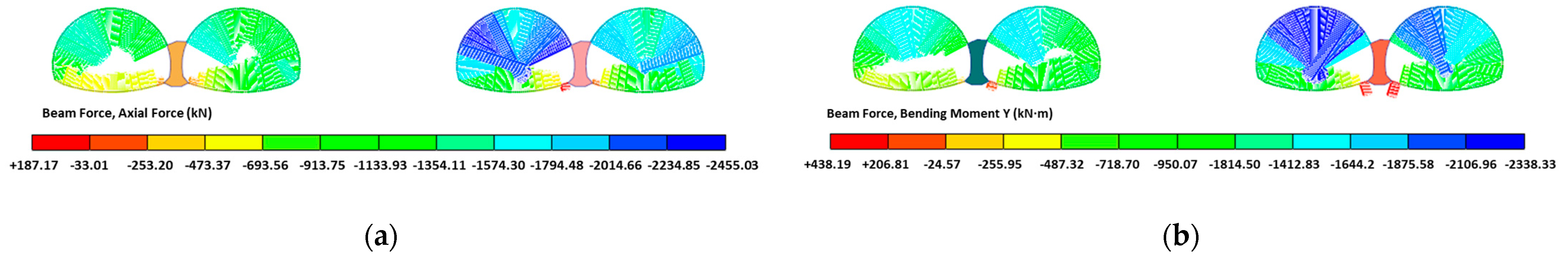
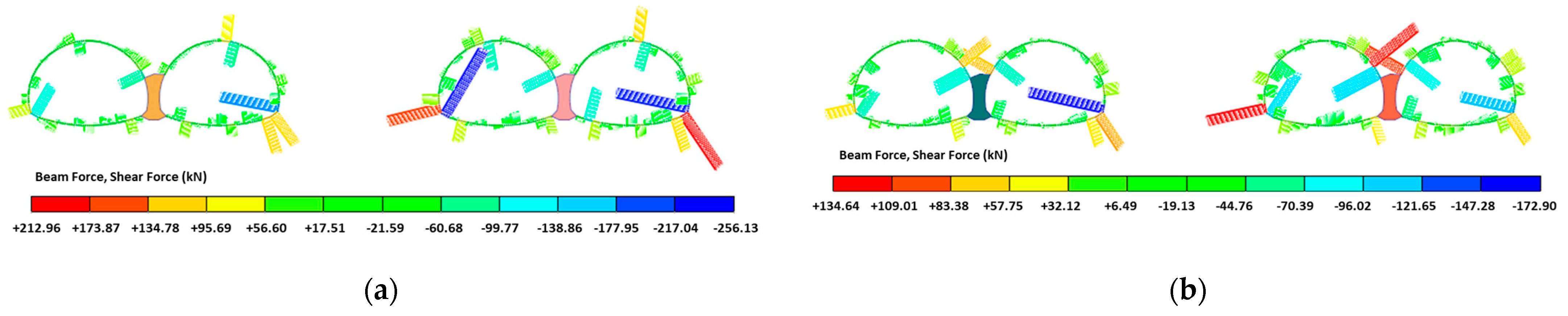
- Stress analysis of the support structure
- (2)
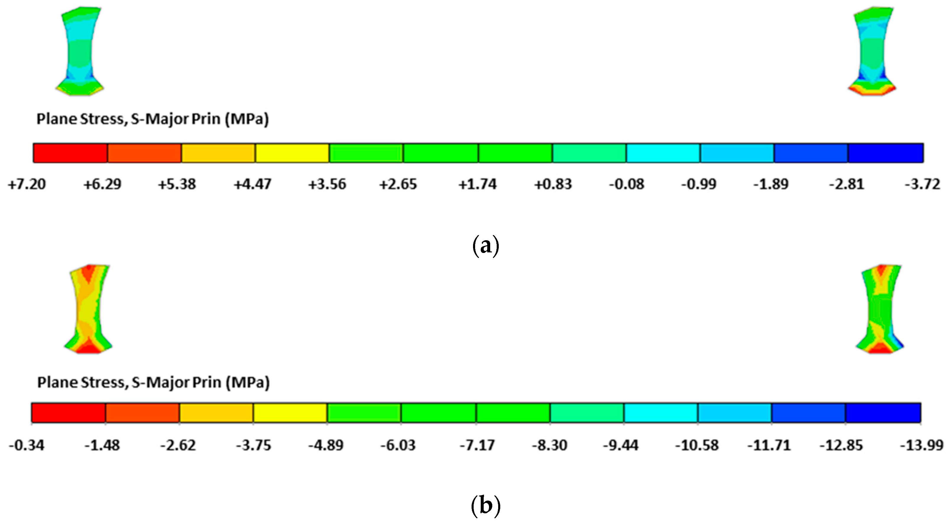
- Stress analysis of the middle partition wall
4.1.3. Determination of Excavation Sequence
4.2. Analysis of Excavation Methods
4.2.1. Plastic Zone Analysis
4.2.2. Deformation Analysis
- (1)
- Deformation analysis of the surrounding rock and tunnel
- (2)
- Tipping analysis of the middle partition wall
4.2.3. Force Analysis
- (1)
- Force analysis of the support structure
- (2)
- Stress analysis of the middle partition wall
4.2.4. Determination of Excavation Method
4.3. Adjustment of Construction Methods
4.3.1. Adjusting the Construction Method to Three-Step Excavation Method
4.3.2. Anchoring of the Middle Partition Wall
5. Conclusions
- (1)
- Under the asymmetrical load, the deformation and force of the surrounding rock were greater on the deeply buried side. The tipping deformation of both middle partition walls was toward the shallow side. The tipping magnitude of the middle partition wall on the shallow side was greater;
- (2)
- The effect of the excavation sequence on horizontal deformation was greater than that of vertical deformation. If the shallow side is excavated first, the asymmetric load generated by the construction and the topography are opposite. This was more conducive to the safety of the tunnel;
- (3)
- In this project, the mutual influence generated by the construction of the left line and the right line was not significant. Therefore, the excavation sequence of either “1→2→3→4” or “3→4→1→2” was feasible;
- (4)
- In terms of the surrounding rock deformation and plastic zone, the Center Diaphragm Excavation Method was slightly better than the Three-bench Excavation Method. In terms of the support structure force, the Center Diaphragm Excavation Method was slightly inferior to the Three-bench Excavation Method;
- (5)
- The index difference between the Center Diaphragm Excavation Method and the Three-bench Excavation Method was not large, and the settlement of the vault was 1.33 cm and 1.48 cm, respectively, which is within a safe range. The Three-bench Excavation Method is more economical; therefore, it is recommended;
- (6)
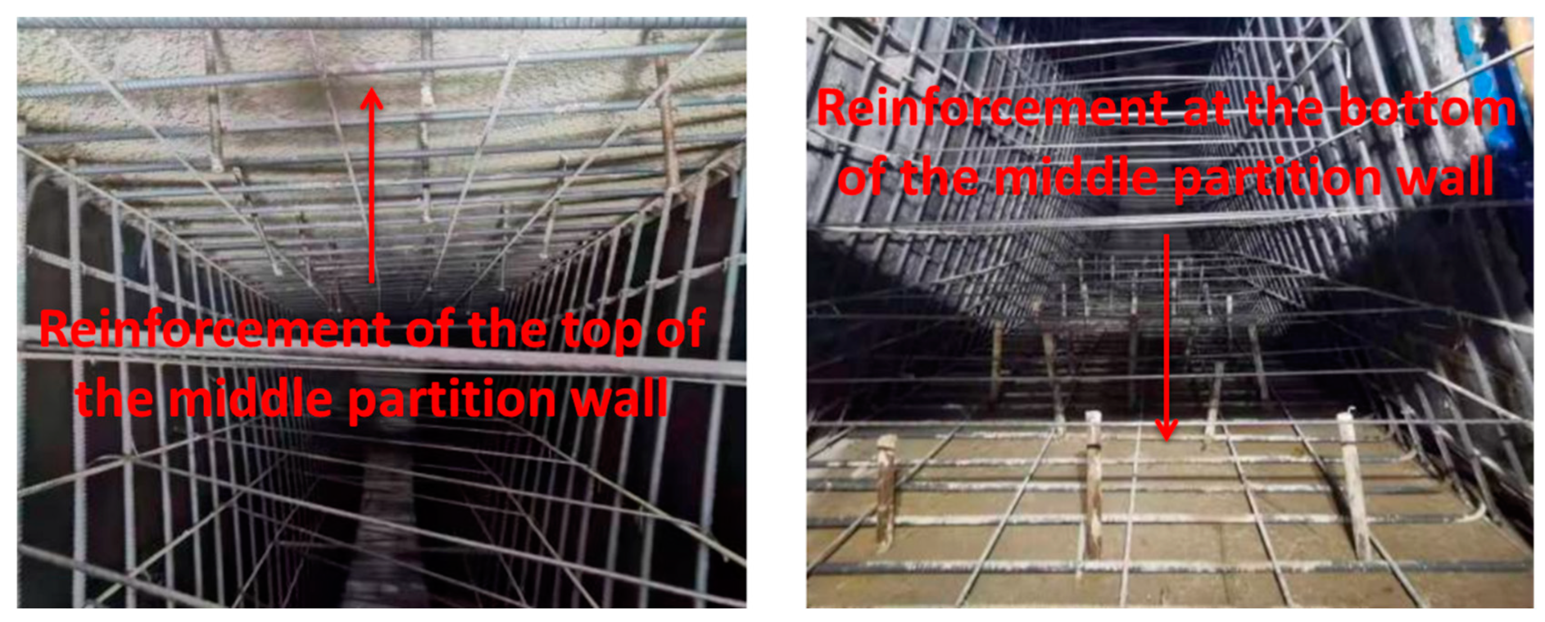
- Based on the numerical simulation results, the construction sequence of the shallow-buried side of the tunnel first was adopted in the actual construction process. The excavation method was adjusted to the Three-bench Excavation Method. The top and bottom of the middle partition wall were reinforced with anchors.
Author Contributions
Funding
Data Availability Statement
Acknowledgments
Conflicts of Interest
References
- Jiang, Q.; Song, S.-G.; Li, T.; Wang, K.; Gu, R.-H. Study on Surrounding Rock Stability of Small Clear-Distance Twin Highway Tunnel with Eight Lanes. Geotech. Geol. Eng. 2019, 37, 593–598. [Google Scholar] [CrossRef]
- Li, R.; Chen, P.; Zhang, D.L.; Wang, S.T.; Shen, Z.J.; Pan, H.G. Numerical study and engineering practice for surrounding rock stability of large cross-sectional triple tunnels. China Civ. Eng. J. 2022, 55, 83–95. [Google Scholar] [CrossRef]
- Xue, Y.; Gong, H.; Kong, F.; Yang, W.; Qiu, D.; Zhou, B. Stability analysis and optimization of excavation method of double-arch tunnel with an extra-large span based on numerical investigation. Front. Struct. Civ. Eng. 2021, 15, 136–146. [Google Scholar] [CrossRef]
- Wang, J.; Cao, A.; Wu, Z.; Sun, Z.; Lin, X.; Sun, L.; Liu, X.; Li, H.; Sun, Y. Numerical Simulation of Ultra-Shallow Buried Large-Span Double-Arch Tunnel Excavated under an Expressway. Appl. Sci. 2022, 12, 39. [Google Scholar] [CrossRef]
- Fu, J.; Yang, J.; Yan, L.; Abbas, S.M. An analytical solution for deforming twin-parallel tunnels in an elastic half plane. Int. J. Numer. Anal. Methods Geomech. 2015, 39, 524–538. [Google Scholar] [CrossRef]
- Li, G.J.; Zhai, Y.; Lu, G.S.; Liu, J.S. Surrounding Rock Pressure of Tunnel with Small Clear Distance under Complex Unsymmetrical Loading: Calculation and Parameter Impacts. J. Yangtze River Sci. Res. Inst. 2020, 37, 133–138. [Google Scholar]
- Yang, S.; Dai, R.; Ai, Z.; Li, X.; Zhang, C.; Huang, X. Analytical Solutions for the Mechanical Responses of Shallow Double-Arched Tunnel Subjected to Symmetric Loads. Adv. Civ. Eng. 2021, 2021, 8867536. [Google Scholar] [CrossRef]
- Hu, X.; Zhang, Z.; Teng, L. An analytical method for internal forces in DOT shield-driven tunnel. Tunn. Undergr. Space Technol. 2009, 24, 675–688. [Google Scholar] [CrossRef]
- Yao, Y.; He, C.; Zhang, L.L. Experimental Study of Site Monitoring of Zipingpu Tunnel with Small Clear Spacing. Chin. J. Rock Mech. Eng. 2010, 29, 3295–3300. [Google Scholar]
- Wu, J.M.; Chen, X.C.; Li, W.Q.; Peng, J.Z.; Zhang, A.L. Forecast of overbreak and analysis of cause of formation in double-arch tunnels in Jinliwen highway. Hydrogeol. Eng. Geol. 2005, 32, 56–59. [Google Scholar] [CrossRef]
- Yan, Q.; Zhang, C.; Lin, G.; Wang, B. Field Monitoring of Deformations and Internal Forces of Surrounding Rocks and Lining Structures in the Construction of the Gangkou Double-Arched Tunnel—A Case Study. Appl. Sci. 2017, 7, 169. [Google Scholar] [CrossRef]
- Lai, J.; Qiu, J.; Fan, H.; Chen, J.; Hu, Z.; Zhang, Q.; Wang, J. Structural Safety Assessment of Existing Multiarch Tunnel: A Case Study. Adv. Mater. Sci. Eng. 2017, 2017, 1697041. [Google Scholar] [CrossRef]
- Yuan, Y.; Wang, S.H.; Du, G.P.; Li, D. In-Situ Testing Study on Lining System of doubleArched Tunnel. Chin. J. Rock Mech. Eng. 2005, 24, 480–484. [Google Scholar]
- Lei, M.-F.; Lin, D.-Y.; Yang, W.-C.; Shi, C.-H.; Peng, L.-M.; Huang, J. Model test to investigate failure mechanism and loading characteristics of shallow-bias tunnels with small clear distance. J. Cent. South Univ. 2016, 23, 3312–3321. [Google Scholar] [CrossRef]
- Jiang, X.L.; Wang, F.F.; Yang, H.; Lian, P.Y.; Niu, J.Y. Study on Seismic Lining Strain Law of Shallow-buried Bias Tunnel with Small Clear Distance. Chin. J. Undergr. Space Eng. 2017, 13, 506–516. [Google Scholar]
- Li, S.; Yuan, C.; Feng, X.; Li, S. Mechanical behaviour of a large-span double-arch tunnel. KSCE J. Civ. Eng. 2016, 20, 2737–2745. [Google Scholar] [CrossRef]
- Yang, J.S.; Gou, D.M.; Zhang, Y.X. Field Measurements and Numerical Analyses of Double-Layer Pipe Roof Reinforcement in a Shallow Multiarch Tunnel. Transp. Res. Rec. 2008, 2050, 145–153. [Google Scholar] [CrossRef]
- Liu, X.R.; Liu, J.; Huang, L.H.; Wang, Z.J.; Chen, H.J.; Feng, Y. Model test and pressure arch analysis for excavation of loess double arch tunnel. J. Zhejiang Univ. Eng. Sci. 2018, 52, 1140–1149. [Google Scholar]
- Wang, J.; Cao, A.; Li, Z.; Wu, Z.; Lin, L.; Liu, X.; Li, H.; Sun, Y. Mechanical Behavior and Excavation Optimization of a Small Clear-Distance Tunnel in an Urban Super Large and Complex Underground Interchange Hub. Appl. Sci. 2023, 13, 254. [Google Scholar] [CrossRef]
- Ng, C.W.; Lee, K.M.; Tang, D.K. Three-dimensional numerical investigations of new Austrian tunnelling method (NATM) twin tunnel interactions. Can. Geotech. J. 2004, 41, 523–539. [Google Scholar] [CrossRef]
- Zhang, Y.L.; Fu, X.K.; Liu, H.L.; Zheng, Y.Y. Study on the reasonable excavation sequence of shallow-embedded bias tunnels with small clear distance. J. Railw. Eng. Soc. 2013, 10, 57–63. [Google Scholar] [CrossRef]
- Xu, Q.; Xu, W.; Li, P.; Liu, Y. A Hybrid Construction Method for Shallow Buried Urban Tunnel with Ultra-Small Clear Distance. IOP Conf. Ser. Mater. Sci. Eng. 2020, 960, 032007. [Google Scholar] [CrossRef]
- Soliman, E.; Duddeck, H.; Ahrens, H. Two- and three-dimensional analysis of closely spaced double-tube tunnels. Tunn. Undergr. Space Technol. 1993, 8, 13–18. [Google Scholar] [CrossRef]
- Bai, J.S.; Zhao, S.P.; Qi, B.; Yang, K.F. Study on the structure deformation of large-span shallow-buried multi-arch tunnel in soft stratum. China Civ. Eng. J. 2017, 50, 45–50. [Google Scholar] [CrossRef]
- Yao, A.; Lin, J.; Ren, B. The Influence of Small Clear-Distance Tunnel Construction on Adjacent High-Voltage Transmission Tower Foundation. Adv. Civ. Eng. 2023, 2023, 2533212. [Google Scholar] [CrossRef]
- Qi, H.; Gao, B.; Wang, S.S.; Xu, C. Mechanical Behaviors of a Shallow-Bias Tunnel with a Small Clear Distance in Different Geological Conditions. Mod. Tunn. Technol. 2014, 51, 108–112. [Google Scholar] [CrossRef]
- Zhao, J.P.; Wang, X.Y.; Tan, Z.S.; Zhang, C.; Wang, Z.X. Study on the reasonable construction layout of main tunnel in unsymmetrical loading multi-arch tunnel with weak rock. China Civ. Eng. J. 2017, 50, 66–74. [Google Scholar] [CrossRef]
- Zhang, F. Stability Analysis of Construction Process of New Tunnel Passing through High-speed Railway Foundation. J. Railw. Eng. Soc. 2022, 39, 53–58+79. [Google Scholar]


| Category | Severe (kN/m3) | Elastic Modulus (GPa) | Poisson’s Ratio | Friction Angle (°) | Cohesion (kPa) | Property |
|---|---|---|---|---|---|---|
| Level V Rock Mass | 17 | 1 | 0.37 | 20 | 100 | Plane Strain |
| Initial Support | 23 | 27.2 | 0.2 | / | / | Beam |
| Middle Partition Wall | 25 | 32.5 | 0.2 | / | / | Plane Strain |
| Excavation Sequence | Construction Process |
|---|---|
| 1234 | Excavation 1 → Support 1 → Excavation 2 → Support 2 + Removal of the middle partition wall support 1 → Excavation 3 → Support 3 → Excavation 4 → Support 4 → Removal of the middle partition wall support 2 |
| 1243 | Excavation 1 → Support 1 → Excavation 2 → Support 2 + Removal of the middle partition wall support 1 → Excavation 4 → Support 4 → Excavation 3 → Support 3 + Removal of the middle partition wall support 2 |
| 2134 | Excavation 2 → Support 2 → Excavation 1 → Support 1 + Removal of the middle partition wall support 1 → Excavation 3 → Support 3 → Excavation 4 → Support 4 → Removal of the middle partition wall support 2 |
| 2143 | Excavation 2 → Support 2 → Excavation 1 → Support 1 + Removal of the middle partition wall support 1 → Excavation 4 → Support 4 → Excavation 3 → Support 3 + Removal of the middle partition wall support 2 |
| 3412 | Excavation 3 → Support 3 → Excavation 4 → Support 4 + Removal of the middle partition wall support 2 → Excavation 1 → Support 1 → Excavation 2 → Support 2 + Removal of the middle partition wall support 1 |
| 3421 | Excavation 3 → Support 3 → Excavation 4 → Support 4 + Removal of the middle partition wall support 2 → Excavation 2 → Support 2 → Excavation 1 → Support 1 + Removal of the middle partition wall support 1 |
| 4312 | Excavation 4 → Support 4 → Excavation 3 → Support 3 + Removal of Intermediate Wall Support 2 → Excavation 1 → Support 1 → Excavation 2 → Support 2 + Removal of the middle partition wall support 1 |
| 4321 | Excavation 4 → Support 4 → Excavation 3 → Support 3 + Removal of Intermediate Wall Support 2 → Excavation 2 → Support 2 → Excavation 1 → Support 1 + Removal of the middle partition wall support 1 |
| Excavation Sequence | Tunnel 1 (MPa) | Tunnel 2 (MPa) | The Larger between Tunnel 1 and Tunnel 2 (MPa) | Tunnel 3 (MPa) | Tunnel 4 (MPa) | The Larger between Tunnel 3 and Tunnel 4 (MPa) |
|---|---|---|---|---|---|---|
| 1234 | 5.227 | 5.106 | 5.23 | 10.140 | 5.544 | 10.14 |
| 1243 | 5.262 | 5.145 | 5.26 | 5.330 | 10.750 | 10.75 |
| 2134 | 3.714 | 8.666 | 8.67 | 10.109 | 5.524 | 10.11 |
| 2143 | 3.729 | 8.746 | 8.75 | 5.313 | 10.719 | 10.72 |
| 3412 | 5.986 | 3.760 | 5.99 | 10.186 | 6.000 | 10.19 |
| 3421 | 3.386 | 7.539 | 7.54 | 10.192 | 5.886 | 10.19 |
| 4312 | 5.971 | 3.788 | 5.97 | 5.735 | 10.747 | 10.75 |
| 4321 | 3.401 | 7.585 | 7.59 | 5.702 | 10.708 | 10.71 |
Disclaimer/Publisher’s Note: The statements, opinions and data contained in all publications are solely those of the individual author(s) and contributor(s) and not of MDPI and/or the editor(s). MDPI and/or the editor(s) disclaim responsibility for any injury to people or property resulting from any ideas, methods, instructions or products referred to in the content. |
© 2023 by the authors. Licensee MDPI, Basel, Switzerland. This article is an open access article distributed under the terms and conditions of the Creative Commons Attribution (CC BY) license (https://creativecommons.org/licenses/by/4.0/).
Share and Cite
Wu, S.; Wu, J.; Liu, D. Research on Construction Sequences and Construction Methods of the Small Clear-Distance, Double-Arch Tunnel under an Asymmetrical Load. Appl. Sci. 2023, 13, 8242. https://doi.org/10.3390/app13148242
Wu S, Wu J, Liu D. Research on Construction Sequences and Construction Methods of the Small Clear-Distance, Double-Arch Tunnel under an Asymmetrical Load. Applied Sciences. 2023; 13(14):8242. https://doi.org/10.3390/app13148242
Chicago/Turabian StyleWu, Shan, Jian Wu, and Dunwen Liu. 2023. "Research on Construction Sequences and Construction Methods of the Small Clear-Distance, Double-Arch Tunnel under an Asymmetrical Load" Applied Sciences 13, no. 14: 8242. https://doi.org/10.3390/app13148242
APA StyleWu, S., Wu, J., & Liu, D. (2023). Research on Construction Sequences and Construction Methods of the Small Clear-Distance, Double-Arch Tunnel under an Asymmetrical Load. Applied Sciences, 13(14), 8242. https://doi.org/10.3390/app13148242