Article

Design of Energy Recovery Control for General Virtual Synchronous Machines Based on Various Forms of Energy Storage

1
College of Automation Engineering, Nanjing University of Aeronautics and Astronautics, Nanjing 210016, China
2
AVIC Shenyang Aircraft Design and Research Institute, Shenyang 110035, China
3
School of Automation Science and Electrical Engineering, Beihang University, Beijing 100191, China
4
NARI Group Corporation (State Grid Electric Power Research Institute) Co., Ltd., Nanjing 211006, China
5
Beijing DC Transmission and Distribution Engineering Technology Research Center (China-EPRI Electrical Engineering Co., Ltd.), Beijing 102200, China
6
Beihang School, Beihang University, Beijing 100191, China
7
Department of Electrical and Computer Engineering, McGill University, Montreal QC H3A 0G4, Canada
*
Author to whom correspondence should be addressed.
Appl. Sci. 2023, 13(14), 8059; https://doi.org/10.3390/app13148059
Submission received: 9 June 2023 / Revised: 3 July 2023 / Accepted: 7 July 2023 / Published: 10 July 2023

Abstract

:

Featured Application

This research work may be useful for power converters adopting grid-forming control such as virtual synchronous machine based on various forms of energy storage.

Abstract

The reduced inertia in the power system due to renewable energy integration introduces operation challenges in frequency stability and control. The current options for virtual inertia and frequency support are limited by the energy resources and the power electronic interface. Considering the demand on response speed and energy capacity, a general virtual synchronous machine (VSM) control based on various forms of energy storage systems (ESS) is proposed. The steady-state energy variation of energy storage is found to be proportional to the virtual damping or governor gain, while inversely proportional to the integral gain of system frequency control. It is found that the size of energy storage can be at the second time scale (for example, 6.8 p.u.·s) for VSM implementation, which is significantly smaller than the conventional hour-scale energy storage in the power system. Based on energy dynamic analysis, stability requirement, and bandwidth separation rules, an energy recovery control is designed to maintain constant state of charge (for example, 50%) while avoiding conflicts with frequency regulation. The time scale of the designed energy recovery control loop (for example, hundreds of seconds) is longer than the secondary frequency control. The effectiveness of the proposed control is verified through comprehensive case studies.

1. Introduction

Grid-forming converters, such as virtual synchronous machines (VSM) mimicking the behavior of rotating synchronous generators with static power electronic converters, are deemed as the key technologies to meet the growing challenges of frequency stability in power systems, due to the rapid emergence of renewable energy resources which are synchronized by phase lock loop (PLL) and exhibits no mechanical inertia on the grid side [1]. However, after approximately 20 years after its first proposal, the practical application of VSM in field projects is still relatively rare. As reported, stability, fault-ride-through capability, seamless transition for plug-and-play operation and energy storage are acknowledged as the four major bottlenecks for practical power system applications [2]. Among them, stability and fault ride through can be addressed by proper tuning of the control parameters or coordination with protection, which have been extensively reported in the literature [3,4,5,6,7,8]. By contrast, less research covered the slower dynamics of VSM such as the energy management in VSM operation.

1.1. History and State of the Art of ESS-Based VSM

The research of VSM in the early stage focused mainly on the control architecture. Though varying in structure, the basic functions can all be treated as equivalent or similar to droop control, by proper control block transformation [9].
Beck and Hesse first proposed the concept of the virtual synchronous machine. Based on the stator emulation equation, the control architecture can be further categorized into two types: voltage to current or current to voltage [10]. Higher-order models of synchronous generators can also be emulated [11]. A VSM model with first-order droop characteristic was adopted in the Europe virtual synchronous (VSYNC) project [12]. As PLL is needed to measure system frequency, this type of VSM is essentially a current source and cannot operate independently. Zhong et al. proposed a synchronverter that can emulate both rotor torque and stator voltage characteristics of a synchronous generator with a second-order model [13]. Another VSM topology starts directly from the swing equation [14]. The governor control emulation is presented as a first-order lag element and the stator impedance is also synthesized. Compared with the above VSM concepts, active power is used instead of torque in the swing equation formulation [15]. Grid-forming droop control was proposed as one core control option in microgrid [16]. Assuming inductive grid impedance, frequency, and voltage magnitude can be drooped with output active power and reactive power, respectively. Often a low-pass filter is added after the active power measurement of droop control, making it equivalent to the swing equation but easier to implement than the higher-order-based VSM [17].
Most of the VSM control concepts reviewed above assume an ideal DC bus, which is problematic for practical VSM operation, as most energy resources such as renewable generators adopting maximum point power tracking (MPPT) control, are non-dispatchable and normally do not have sufficient energy reserve for frequency support. By contrast, energy storage system (ESS) with bidirectional power regulation capability is the first choice in VSM realization [10]. Though there are various types of ESS for VSMs, the high cost, limited energy capacity, and response speed of ESS remain as the primary concerns [18]. The amount of energy within ESS, usually measured by state of charge (SoC), must be kept within a reasonable range for secure and sustainable operation.
To prevent over-charging/discharging, an SoC feedback control for ESS-based VSM is proposed in Shi et al.’s report [19], but such control cannot ensure constant energy reserve, since it is triggered by SoC-limit violation signals. As reported in Yuan et al.’s research [20], the capacity and action time of ESS for a single grid-connected VSM are determined in over-damped, under-damped and critically damped scenarios. However, the theoretical analysis is not applicable if the frequency control on the grid side is considered, for example, in islanded microgrids.
An enhanced VSM control for short-term ESS integrated with a type-IV wind turbine generator is proposed in Ma et al’s research [21], where proportional-integral (PI) control is added to manage the SoC of ESS. However, the PI control is implemented on the machine-side converter of the wind turbine generator. Therefore, the PI parameters should be adjusted continuously in different rotor speed ranges. Specifically, the PI parameters should be positive or negative based on the signs of slopes of the wind speed and power characteristics.
In Fang et al.’s work [22], the constraints of DC voltage deviation, load disturbance, and maximum frequency deviation are considered in inertia synthesis. Nonetheless, the load disturbance is very small (3–5%) to justify the use of a DC capacitor for VSMs. The same authors proposed a VSM control based on hybrid ESS, in which the battery tackles the slow-varying dynamics while the supercapacitor supplies fast-varying components [23]. However, the energy constraint of a supercapacitor is not explicitly addressed [24]. Besides energy storage in the strict sense, there are VSM implementations based on other energy resources and systems, including photovoltaic and wind generators, controllable load, electric vehicles, high voltage direct current (HVDC) transmission systems, and flexible alternating current transmission system (FACTS) devices [25].
However, most studies are focused on frequency performance and stability improvement, while ignoring the energy constraints. A more practical VSM implementation by accumulating sufficient energy based on cloud energy storage is proposed in Ebrahimi et al.’s work [26], but the energy consumed in ESS for such VSM services is not quantified. The key literature related to the energy variation and management of ESS-based VSM is summarized in Table 1.

1.2. Research Gap

Compared with the early stage of VSM focused on control and stability [9], it is gradually clear that energy capacity and response speed are the main constraints for energy storage to realize VSM control. However, the existing analysis mainly focuses on specific types of energy storage, there is a lack of research into energy capacity and power needs for general types of storage, and then providing guidelines for specific ESS types.
Across the studies, although some researchers noticed the importance of keeping a necessary energy reserve for continuous VSM operation [26], there is a lack of proper energy recovery control applied to the ESS-based VSM, especially for the one with small-sized ESS (i.e., energy capacity at the second-to-minute time scale, compared with the capacity at the hour time scale, for the rated discharging speed). Specifically, the parameter design of energy recovery control, and the impact of such control on system frequency control, were rarely studied.

1.3. Contributions

This research tries to fill the research gaps identified above. The contributions of the paper mainly include the following three aspects, and are validated with comprehensive case studies.
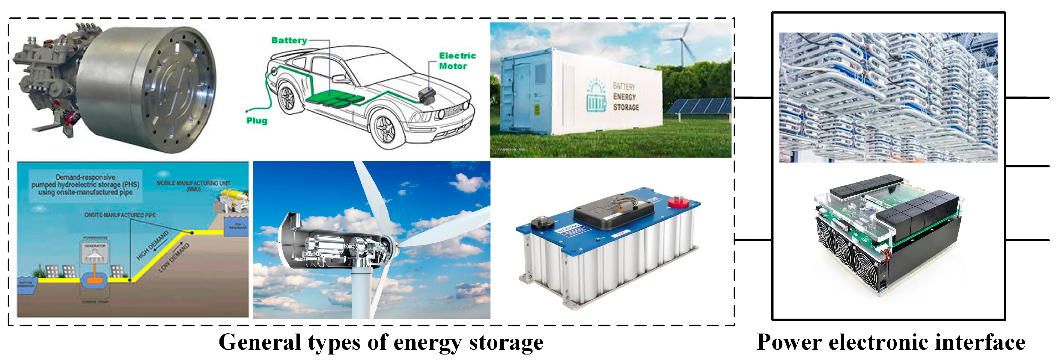
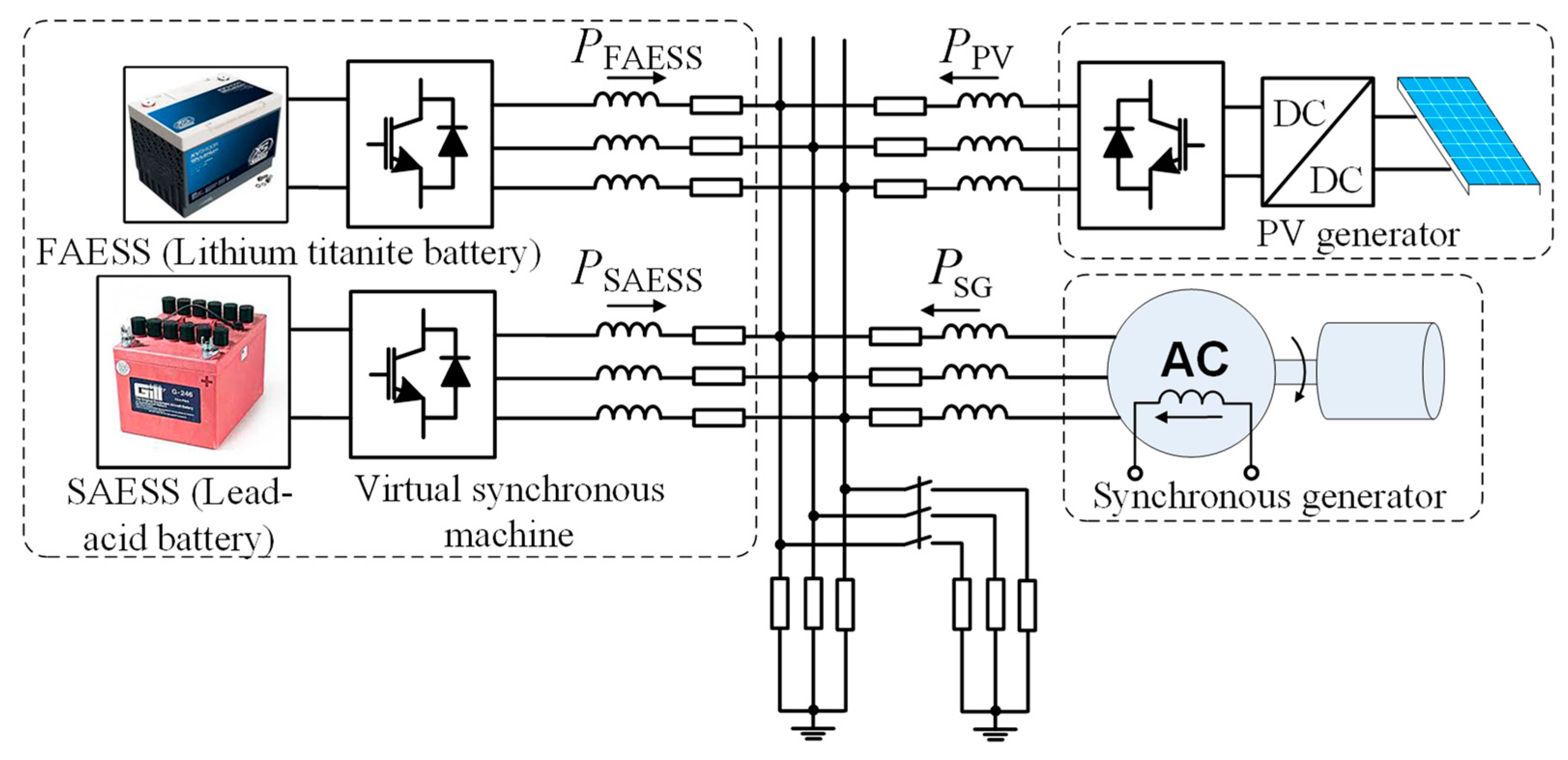
  • General installation types of power electronic converters for ESS-based VSM, including a single ESS, and hybrid ESS realized by DC and AC coupled schemes, are introduced, which broaden the options of VSM realization compared with the existing control strategies based on specific energy storage installation.
  • The steady-state energy variation of ESS regarding the control parameters of VSM, such as virtual governor, damping, and frequency integral control gain, is quantified, which provides a rough estimation of the margin needed when determining those parameters.
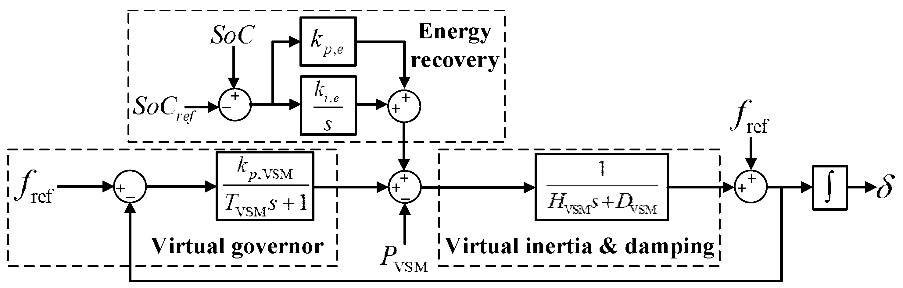
  • A supplementary energy recovery control in addition to the VSM control on the grid-side DC–AC converter is proposed, thereby restoring the energy losses and ensuring energy reserve for continuous VSM operation. The control parameter design ensures high stability and bandwidth separation between energy recovery and the frequency control loop.
The rest of the paper is organized as follows. The general ESS types, the associated power electronic interface, and the general VSM control with energy recovery capability, are introduced in Section 2. Theoretical analysis of the energy variation of ESS in frequency response, the bandwidth rule to design the energy recovery control, and the whole procedure of designing ESS-based VSM, are given in Section 3. Various case studies are presented in Section 4 to validate the proposed general ESS-based VSM with energy recovery control. Section 5 points out the limitations of the current work. Section 6 concludes the article and gives recommendations on future research directions.

2. General ESS-Based VSM with Energy Recovery Control

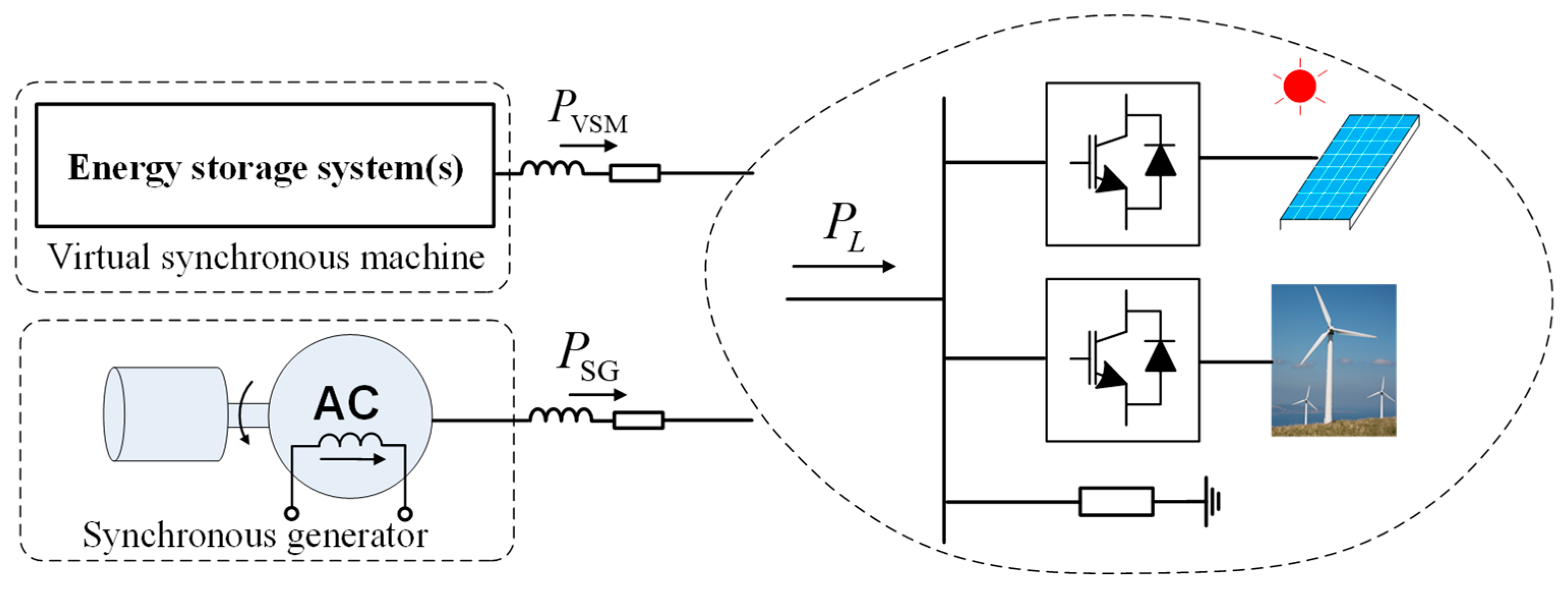
2.1. Significance of General ESS-Based VSM

As most of the previous work on ESS-based VSM is restricted to specific ESS type or application, the proposed general ESS-based VSM expands the candidates for VSM.
Given the high cost of energy storage, utilizing “general” types of energy storage in the power system is essential for the large-scale grid-forming converters, such as virtual synchronous machine. At present, energy storage in the narrow sense, such as battery, is technically immature for large-scale application in the power system, while the dominant renewable energy resources such as PV generator do not have the energy reserve for VSM realization. For a desired virtual inertia and damping value, there may be scenarios that the conventional energy storage is insufficient to synthesize it. As such, general types of energy storage such as an electrochemical battery, a supercapacitor, a flywheel, compressed air storage, a hydro-pump and the energy in a wind turbine rotor can all be considered as candidates for VSM implementation, thus broadening the candidates for VSM implementation. Microgrids, cloud energy storage, electric vehicle fleet, HVDC, wind farm, FACTS, etc., can all be utilized to realize VSM. The general VSM based on various forms of ESS is illustrated in Figure 1.
However, in generalizing energy storage for VSM, not all storage types are suitable for the VSM application, due to their constraints in energy capacity and response speed [27]. The frequency support from VSM can be temporally decomposed into two parts, namely inertial response and governor control. The former is more speed demanding while the latter is more energy capacity demanding. The inertia and governor emulation control in VSM can be assigned to hybrid ESS or a single ESS. The hybrid ESS usually comprises fasting-acting ESS (FAESS) and slow-acting ESS (SAESS). A comparison of different energy storage techniques in response speed vs. power capacity, and power density vs. energy density, are presented in Figure 2 and Figure 3 [28,29]. FAESS such as a supercapacitor, flywheel or lithium–titanite battery, features high power capacity, fast response but small energy capacity. Therefore, it is more suitable for inertial response. By contrast, SAESS such as lead–acid, sodium–sulfur (NaS) or nickel–cadmium (NiCd) batteries, have a larger energy capacity but respond relatively slower. Hence, it is more suitable for virtual governor control. As inertial response is the core function of VSM, FAESS is the indispensable part.

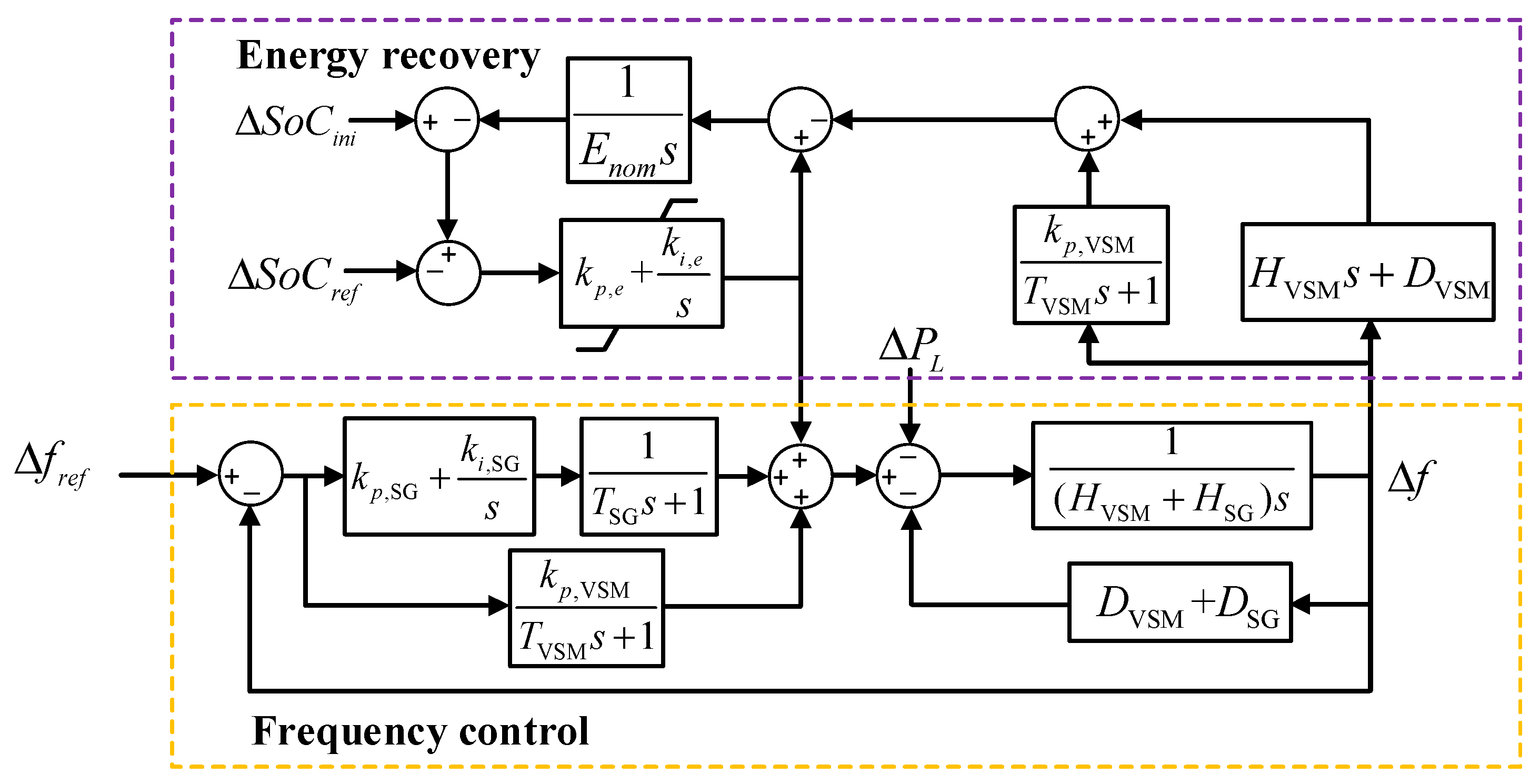
2.2. General ESS-Based VSM with Energy Recovery Control

The power electronic converter interface for VSM implementation may vary with the installation and application of ESS. The energy storage for VSM implementation can be batteries located on the generator or load side [30,31]. The installation of storage can be either centralized, including a large-scale battery storage station in the generation, transmission, and distribution system levels, or distributed, including a small-scale electric vehicle battery, a factory or family back-up storage [32]. In the latter case, proper ESS aggregation and dissemination of the total charging and discharging demand of the electric vehicle batteries are needed to form as a qualified player in the frequency system. As illustrated in Figure 1, this can be electric vehicle batteries interfaced by a DC–AC converter, or hydro-pump storage, a flywheel and a diesel generator interfaced by AC-DC–AC converter [33]. Due to isolation of the rotational speed from grid frequency in the latter case, more speed variation and thus more kinetic energy can be excavated from ESS for VSM implementation compared with directly connected synchronous generator.
In general, VSM can be implemented on a single ESS with a high response speed and proper energy capacity, for example a supercapacitor or lithium–titanite battery, especially in small-scale power network, as Figure 4a shows. However, since a single ESS with both large energy capacity and high response speed is still technically immature and economically less profitable, hybrid storage combining both FAESS and SAESS may be a more feasible solution. Based on the connection topology, hybrid ESS can be DC or AC coupled, as shown in Figure 4b,c, respectively.
VSM control for “general” forms of energy storage installation in the power system is of fundamental importance. Given such complexity of energy storage installation, it is meaningful to develop a “general” VSM control, regardless of the ESS installation or the interfacing topology, as illustrated in Figure 5. For one set of VSM control parameters, the dynamic performance of power and frequency will be equivalent, no matter the VSM is based on a single ESS, hybrid DC- or AC-couple ESS. To compensate for the energy losses and reduce the energy capacity needed, an energy recovery loop is also added to VSM control, except for conventional virtual inertial, damping and governor control.

3. Dynamic Analysis and Design for General VSM with Energy Recovery Control

A general power network shown in Figure 6 is taken as an example here, which consists of a synchronous generator (SG), an ESS-based VSM, and connected networks with other normally non-dispatchable devices such as renewable energy generators and loads. For simplicity, the renewable energy resources operating in MPPT mode, adopt grid-following control and have no frequency support function. Therefore, it is treated as “negative load” in net load calculation. More complex networks can be analyzed similarly. The ESS configuration is general enough to cover both the single ESS and the hybrid ESS topologies in Figure 4.

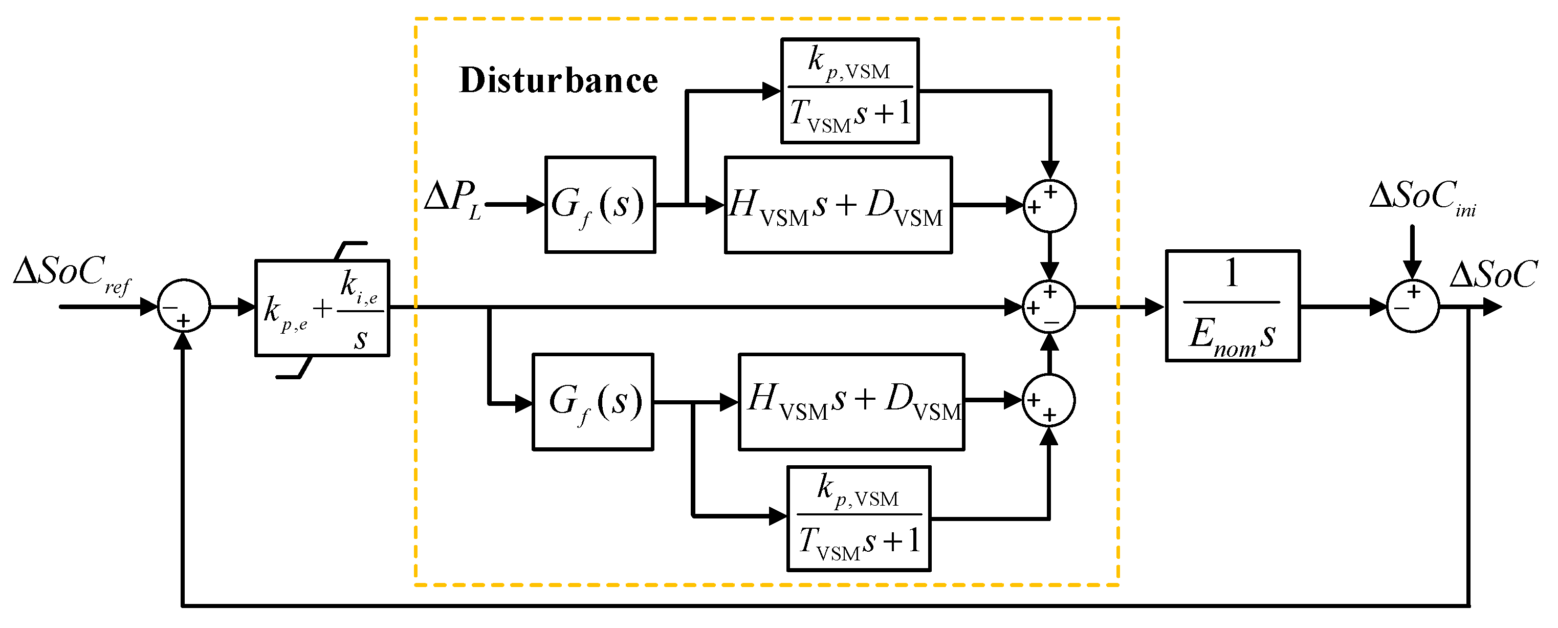
3.1. Frequency, Power and Energy Dynamics

As energy recovery control is a slower process, it is first ignored first. The power–frequency dynamics due to the power disturbance ΔPL can be estimated by Equations (1)–(4), where H and D denote the inertia and damping, kp and ki are the governor gain and integral gain in frequency control, the subscripts “SG” and “VSM” represent synchronous generator and virtual synchronous machine, ΔPSG, ΔPHD, ΔPGov represent the power of SG, virtual inertia and damping, and virtual governor, respectively.
Δ f ( s ) = G f ( s ) Δ P L = ( T VSM s + 1 ) ( T SG s + 1 ) s { ( ( H VSM + H SG ) s + D VSM + D SG ) ( T VSM s + 1 ) ( T SG s + 1 ) s + k p , VSM s ( T SG s + 1 ) + ( k p , SG s + k i , SG ) ( T VSM s + 1 ) } Δ P L
Δ P SG ( s ) = ( k p , SG + k i , SG / s T SG s + 1 + ( H SG s + D SG ) ) Δ f ( s )
Δ P HD ( s ) = ( H VSM s + D VSM ) Δ f ( s )
Δ P Gov ( s ) = k p , VSM T V S M S Δ f ( s )
As observed, the power dynamics of virtual inertia and damping control behave like a high-pass filter (HPF) process, while the power dynamics due to virtual governor control exhibits a low-pass filter (LPF) behavior. The VSM control with adjustable inertia, damping and governor control may outperform conventional synchronous generator with fixed inertia and little damping. Though larger inertia value is preferred to improve frequency performance, too large inertia will result in oscillation and slow frequency regulation [34]. Moreover, the inertia value is limited by the energy capacity of storage [1].
The steady-state energy variation of ESS in virtual inertia and damping (ΔEHD), and governor control (ΔEGov), is estimated by Equation (5), based on final value theorem. If both control loops are implemented on one ESS, the total steady-state energy variation of VSM is given by Equation (6). The energy variation can be used as a criterion to size ESS in VSM application. Compared with the research work [21], the integral frequency control gain of synchronous generator (ki,SG), is found related with the energy variation of VSM.
Δ E HD = lim s 0 s Δ E HD ( s ) = Δ P HD ( s ) | s 0 = D VSM k i , SG Δ P L Δ E Gov = lim s 0 s Δ E Gov ( s ) = Δ P Gov ( s ) | s 0 = k p , VSM k i , SG Δ P L
Δ E VSM = D VSM + k p , VSM k i , SG Δ P L
The above analysis indicates that both virtual damping and governor will cause energy dissipation, for which the ESS must be sized properly. The energy recovery control, however, can reduce the size of storage needed.

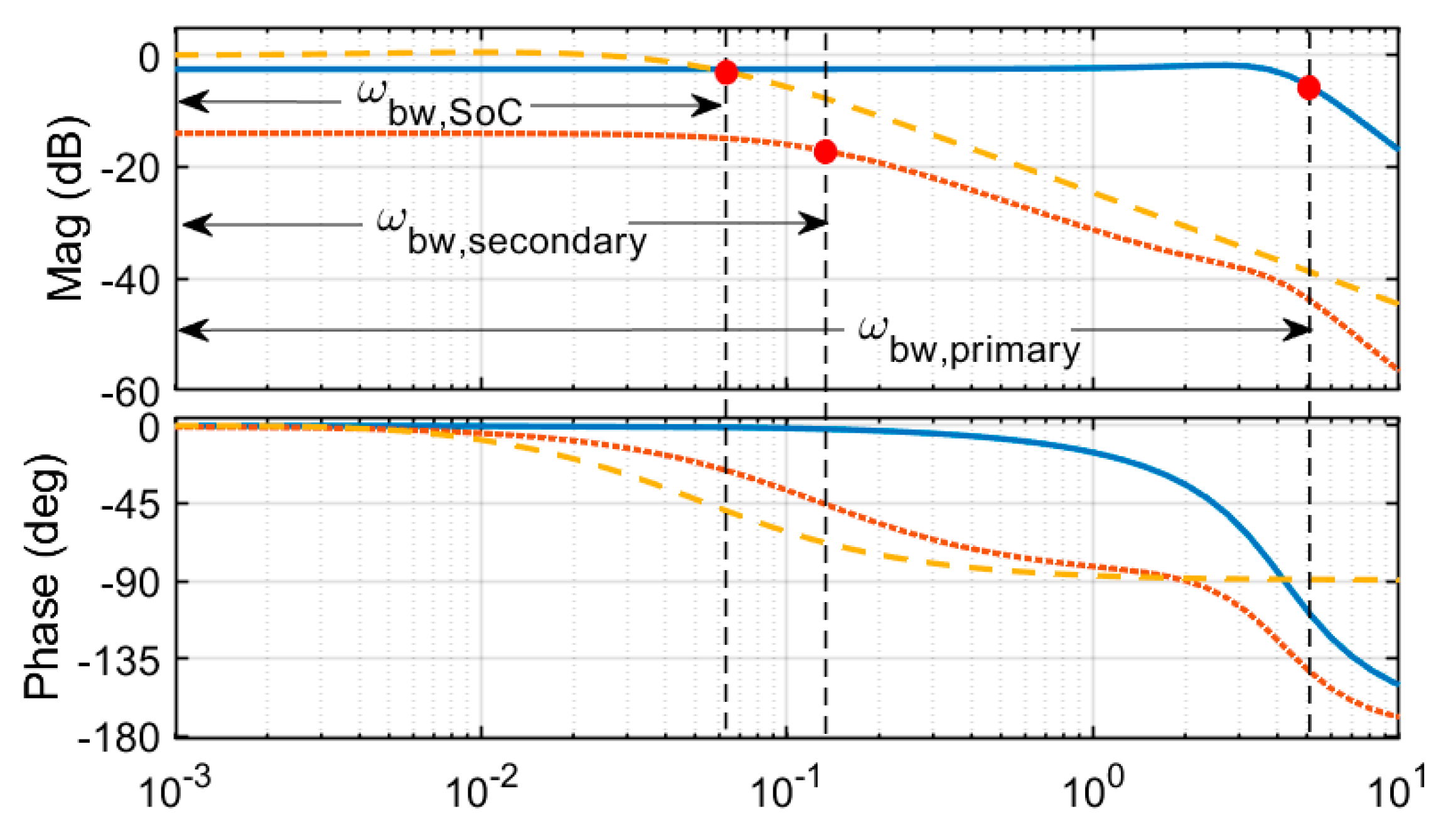
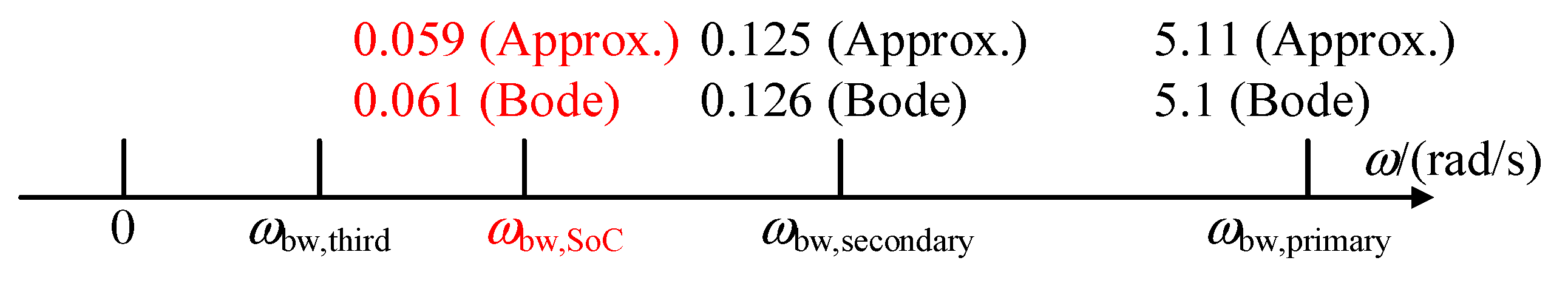
3.2. Bandwidth Separation Design for Frequency and SoC Control

Combining the model of conventional synchronous generator and VSM, we obtain the simplified frequency control as sketched in Figure 7, where the total inertia and damping are calculated by HSG + HVSM and DSG + DVSM, respectively. Setting s = 0 in governor control, the bandwidth of primary control (ωbw,primary) can be roughly estimated by Equation (7), indicating larger inertia will result in slower primary control.
ω bw , primary = k p , VSM + k p , SG + D VSM + D SG H VSM + H SG
The bandwidth of secondary frequency control, ωbw,secondary, can be evaluated from Gf(s)/s. Since ωbw,secondary should be much smaller than ωbw,primary, the simplified secondary control model can be obtained and ωbw,secondary is then estimated as Equation (8), indicating larger governor gain will lead to slower frequency recovery.
ω bw , secondary = k i , SG k p , SG + k p , VSM + D SG + D VSM
Compared with conventional frequency regulation scheme, energy recovery control of VSM is also considered in the model, where Enom and SoCini are the energy capacity and the initial SoC of ESS, kp,e and ki,e denote the proportional and integral gain of SoC recovery control, respectively. By including the effect of frequency control as power disturbance, the SoC recovery control loop of VSM can be redrawn as Figure 8. As the outermost loop, the bandwidth (ωbw,SoC) of the simplified SoC control loop Ge(s) should be lower than that of frequency regulation (ωbw,secondary), which is approximated by Equation (9). Obviously, larger energy capacity will result in slower energy recovery.
ω bw , Soc = k p , e E n o m
Since the control plant in energy recovery is an integral block, a proportional block can normally achieve zero steady-state error. However, considering the parasitic losses of ESS, an integral block (ki,e/s) is added in the SoC recovery control. For the parameters in Table 2, a small ki,e value (0.002) is selected so as to ensure proper damping and keep the original bandwidth. As observed, faster energy recovery can be achieved by larger values of kp,e and ki,e, but the frequency performance may be undermined due to the interaction of the two control loops. Therefore, bandwidth separation must be guaranteed when selecting the frequency and energy control parameters.
Bode plots of primary frequency, secondary frequency and energy recovery control, are presented in Figure 9. The estimated bandwidth values of the three control loops as marked, clearly conform to the bandwidth separation law. The bandwidth values picked from the bode plots of Gf(s) and Ge(s) are also close to the analytical estimation in Equations (7)–(9), as demonstrated in Figure 10. Notice that the bandwidth of energy recovery control should be higher than that of third frequency control (ωbw,third) to avoid the interference into the normal energy management [35].

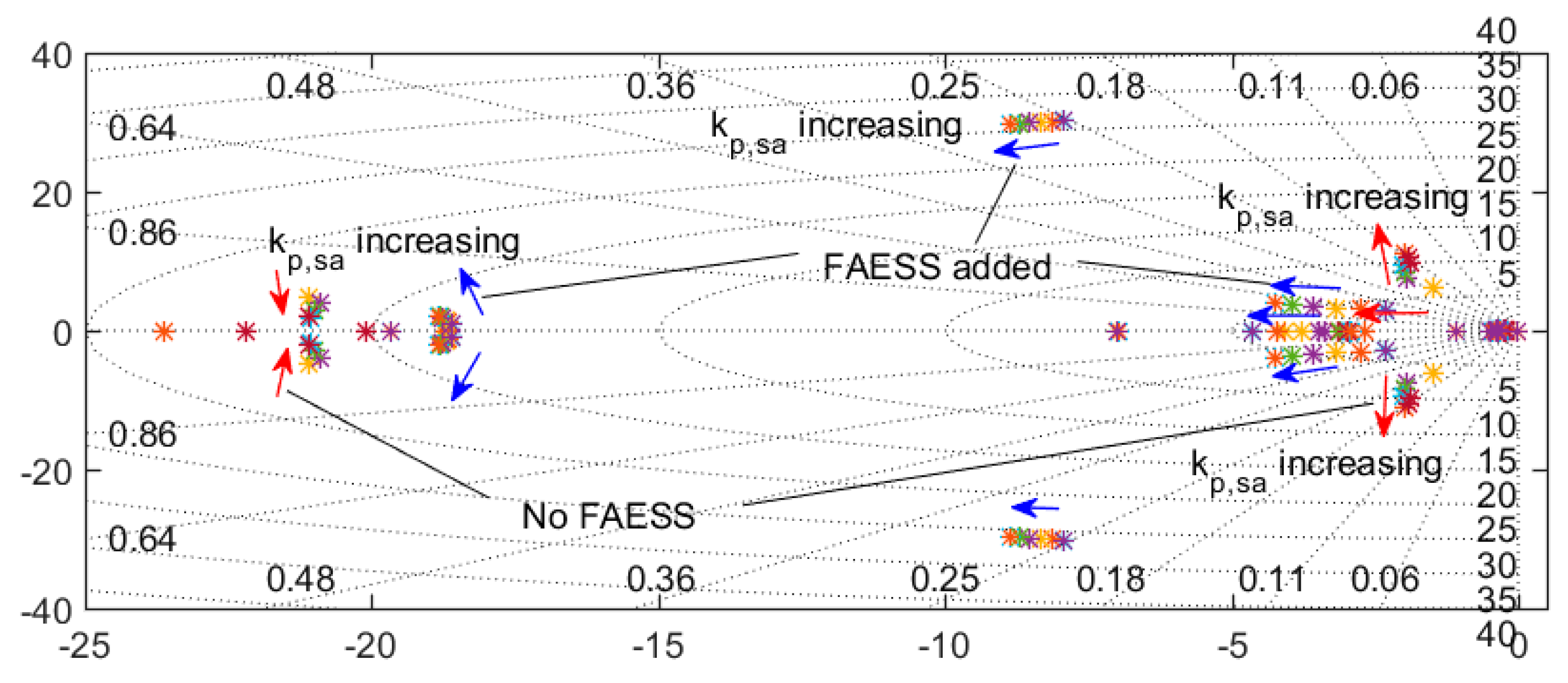
3.3. Parameter Design Considering Stability Requirement

Overall system stability requirement should also be met when designing the VSM parameters such as the virtual inertia and damping terms. Eigenvalue analysis is adopted to determine the critical parameters, as exemplified in Figure 11 where VSM based on the hybridization of SAESS and SAESS is considered. The effect of virtual governor gain in SAESS on root locus is examined, with and without FAESS adopting virtual inertia and damping control in the system. As observed, the VSM control from FAESS will enhance system stability. More comprehensive stability analysis can be found in the literature and the authors’ previous work [34]. Notice a small leading term (time constant Th) may be added to alleviate the synchronous and sub-synchronous oscillation modes.
For multiple VSMs in the power system, parameter coherency, namely matched products of inertia and the connecting inductance, is expected to reduce the inter-oscillation among multiple VSMs or conventional synchronous generators.

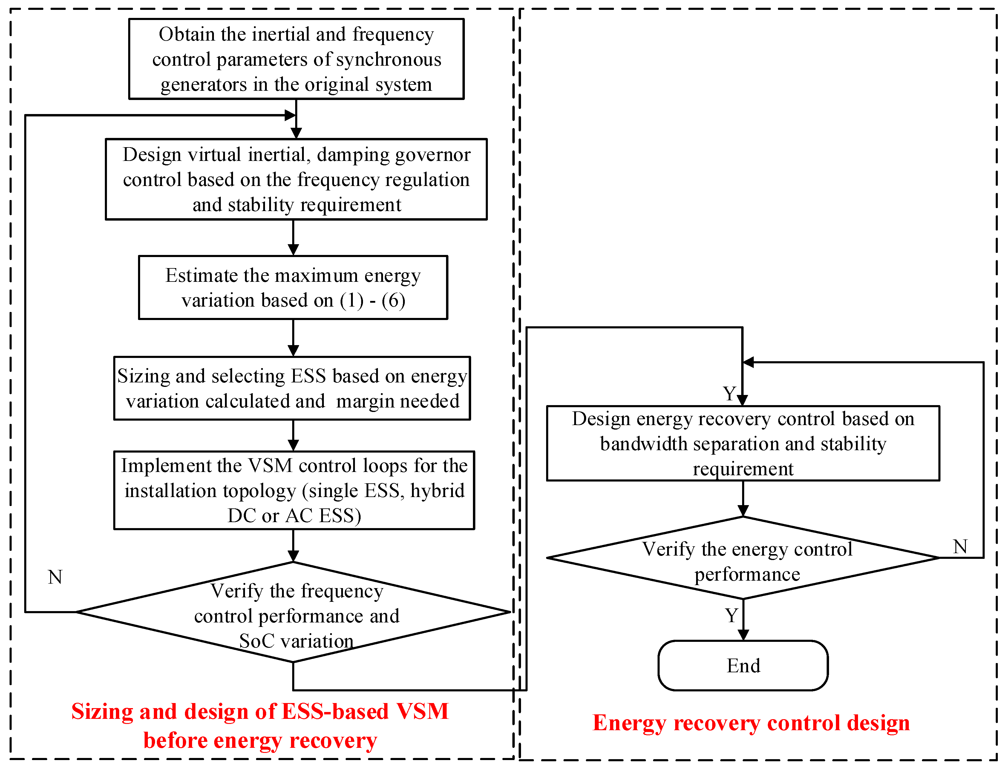
3.4. Control Design and Coordination of General ESS-Based VSM(s)

Based on the theoretical analysis above, the complete procedure of the ESS-based VSM control design is illustrated by Figure 12 and explained below. The control design is independent of the specific energy storage types and power converter topologies, making it general enough to cover VSM implementation in various occasions, without violating the control and physical constraints.
First, the virtual inertia, damping and governor parameters will be designed based on frequency regulation and stability requirement. The ESS will then be sized based on the inertia and damping parameters [1]. Depending on the occasions where VSM is installed and the ESS types selected, proper power electronic interface and control will be designed, for example the single ESS, hybrid DC and AC-coupled ESS discussed above. The steady-state energy variation of ESS will be analyzed and verified.
Afterwards, additional energy recovery control loops will be designed, based on the bandwidth separation rule and stability requirement. Finally, simulation and hardware test will be carried out to verify the VSM control and modify the parameters if necessary.
Notice that it is relatively easy to regulate a limited number of generators in the conventional power system so as to achieve system stability. However, in a future grid with a massive number of distributed grid-forming converters, maintaining system stability will be more challenging. Aggregating coherent VSM as groups will be a promising way to manage these new power system players in the frequency regulation market [32]. Prioritizing multiple ESS in inertia and damping emulation as per the SoC level, or aggregating them based on SoC balancing control, are two options to coordinate the large numbers of VSMs in the power system.

4. Validation of General ESS-Based VSM Control

The system in Figure 6 is modeled and simulated for validation. The model is developed with Matlab/Simulink and run offline in accelerator mode on a personal computer with 8 Intel i7 2.6 GHz CPU cores. Fixed time step 50 us and ode3 (Bogacki-Shampine) solver is used. The model also run successfully on real-time simulator OP5600 [1]. The proposed VSM control is implemented on a single ESS and hybrid AC-coupled ESS, respectively, to validate the general ESS-based VSM with energy recovery control. For brevity of the article and generalization of the VSM control implemented on different ESS installation, a case study of DC-coupled ESS is not presented here. Interested readers can refer to our previous work [1,24] for more details.

4.1. Simulation Test of a Single ESS-Based VSM under Step Load Change

The power network under test is redrawn in Figure 13. The connecting impedances are set at 0.05 p.u., as the normal case. The VSM control is implemented on a single ESS, i.e., lithium titanite battery, as illustrated in Figure 4a. The DC side of ESS is 960 V. This is realized by 240 cells of 2.4 V lithium titanite battery in series. Its energy capacity is 600 Wh. Other parameters for the simulation are listed in Table 2.

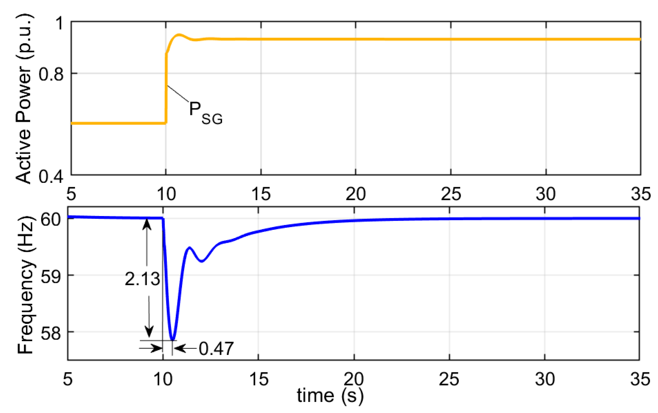
4.1.1. Case 1: Synchronous Generator Only

First, no VSM is present in the system and the SG supplies the total loads. At t = 10 s, there is a 0.375 p.u. active-power load increase, the resulting frequency nadir (i.e., minimum frequency value) is 57.87 Hz at t = 10.47 s, as Figure 14 shows. The large frequency deviation and swing arise from the small inertia and low damping of SG, respectively.

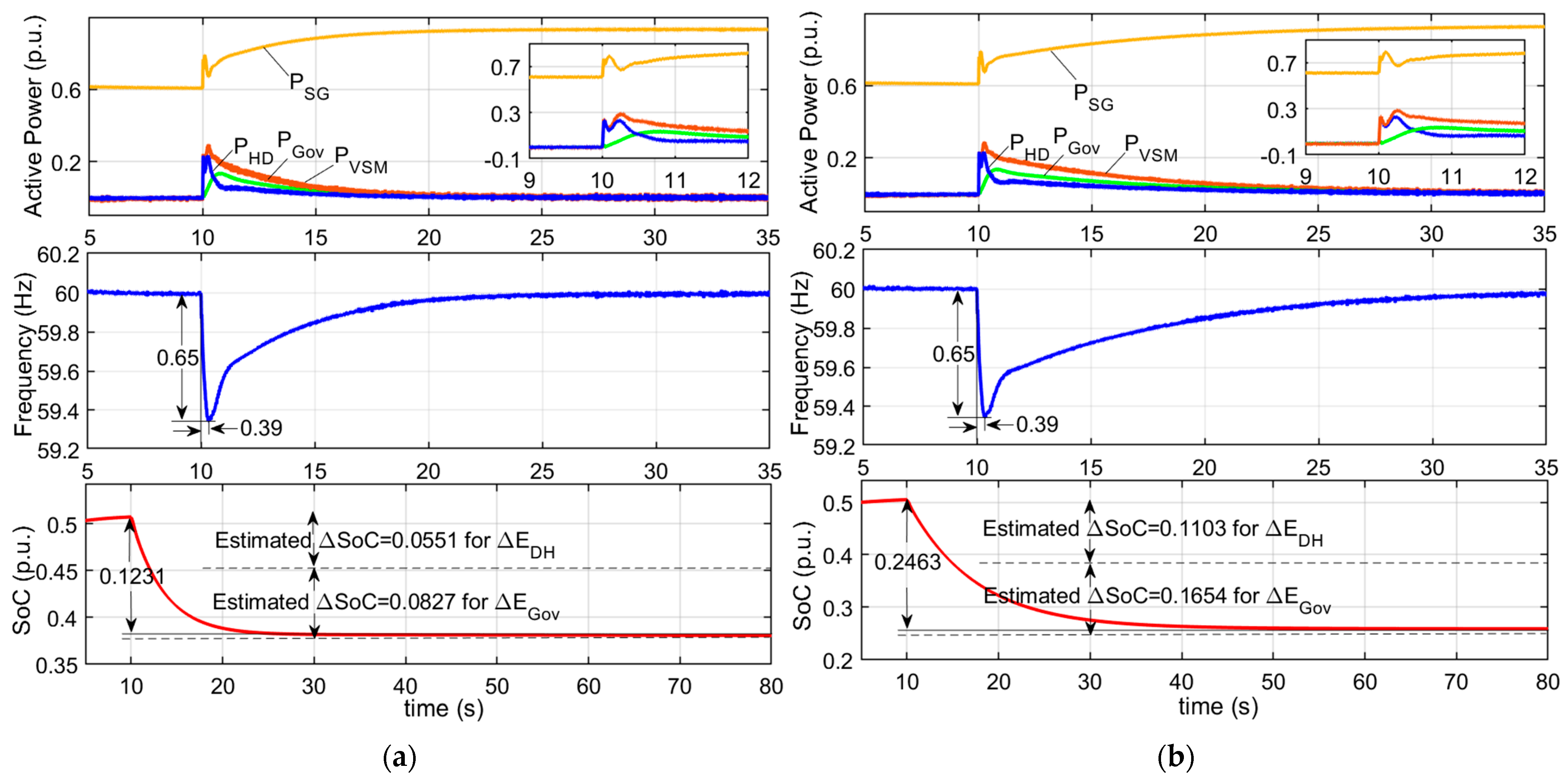
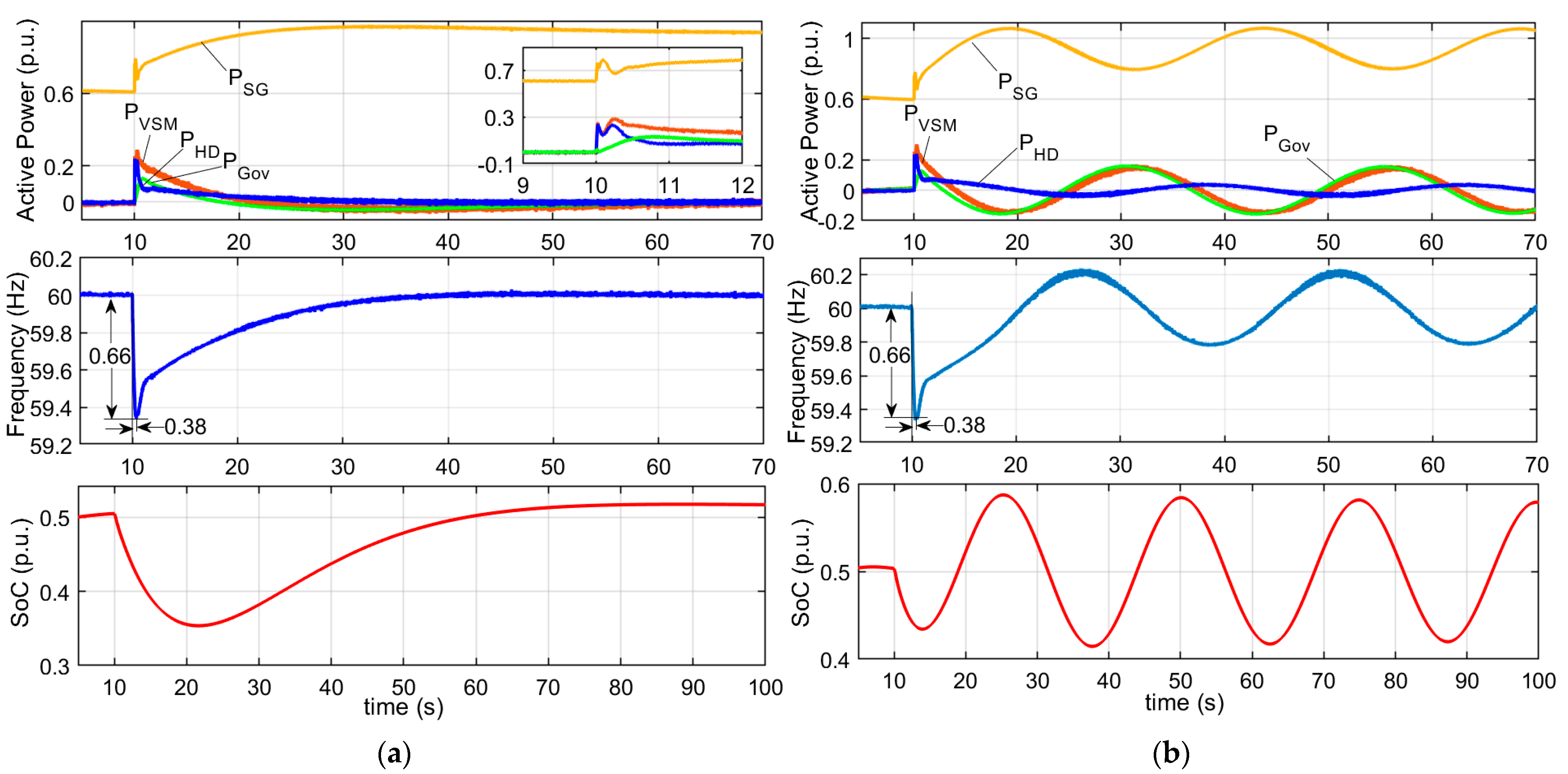
4.1.2. Case 2: Add VSM without Energy Recovery, for Different Frequency Integral Gains

When VSM control without energy recovery is applied to ESS, the frequency nadir becomes 59.35 Hz at t = 10.39 s for the same load change, as shown in Figure 15. The transient power released from ESS in virtual inertia, damping and governor control exhibits HPF and LPF behaviors, in consistent with the transfer functions in Equations (3) and (4). The oscillation in frequency is alleviated due to the damping from ESS. However, the SoC of ESS keeps falling, as with conventional droop-controlled converter.
For frequency integral gain ki,SG = 10, the SoC variation (12.31%), corresponding to both virtual damping and damping, is close to the analytical estimation (Equation (6)), namely
( D VSM + k p , VSM k i , SG Δ P L ) / E n o m = ( 10 + 15 10 · 0.375 ) / 6.8 = 13.79 %
For a smaller frequency integral gain ki,SG= 5, the steady-state energy variation of ESS increases consequently. The SoC variation (24.63%) also approximates the analytical estimation (27.57%) based on Equation (6), namely
( D VSM + k p , VSM k i , SG Δ P L ) / E n o m = ( 10 + 15 10 · 0.375 ) / 6.8 = 27.57 %
Such deep discharging will accelerate ESS aging for long-time operation.

4.1.3. Case 3: Add ESS-Based VSM with Energy Recovery Control

After adding SoC recovery control to the ESS, the frequency nadir becomes 59.34 Hz at t = 10.38 s, as displayed in Figure 16a, which approximates the results above. However, the SoC of ESS gradually returns to 0.5 after frequency regulated to the normal value. The comparison with Figure 15 shows the impact on frequency performance is almost negligible for the selected SoC control parameters. The settling time for SoC recovery is approximately 100 s, which is close to the bandwidth estimation in Equation (9).
If the PI parameters are selected without obeying the bandwidth separation rule, for example kp,e = 1 and ki,e = 0.5, consistent oscillation is observed in the power, frequency and SoC waveforms as Figure 16b, indicating undesirable system stability. The voltage and current exhibits similar shapes, and the system will be forced to shut down.

4.1.4. Summary and Discussion

The control performance in the above tests is summarized in Table 3. The key findings, as also analyzed above, are that the steady-state energy variation of the single-ESS-based VSM is proportional to the sum of virtual governor gain and damping coefficient, while reciprocal to the frequency integral gain of frequency control. The selected PI parameters for SoC recovery produces similar immediate inertial response, but larger PI parameters result in instability because the bandwidth separation rule is defied.
Similar to Ma et al.’s research [21] and the authors’ previous work [1], the test results here also demonstrated the energy variation of ESS-based VSM due to inertial and damping support, as well as the need and effectiveness of energy recovery control. However, compared to the research [21], the oscillation due to improper energy recovery control design is emphasized, and the bandwidth separation rule is highlighted. The work [1] mainly studied VSM based on hybrid ESS, and pointed out the proportional relation between energy deviation and the virtual damping coefficient, while the research work here generalized the energy storage installation for VSM implementation, and validated the reciprocal relation between energy variation and the integral gain of frequency control. Therefore, this work is an efficient supplementary of the previous research, and provides a complete guideline for design VSM control based on various forms of energy storage.

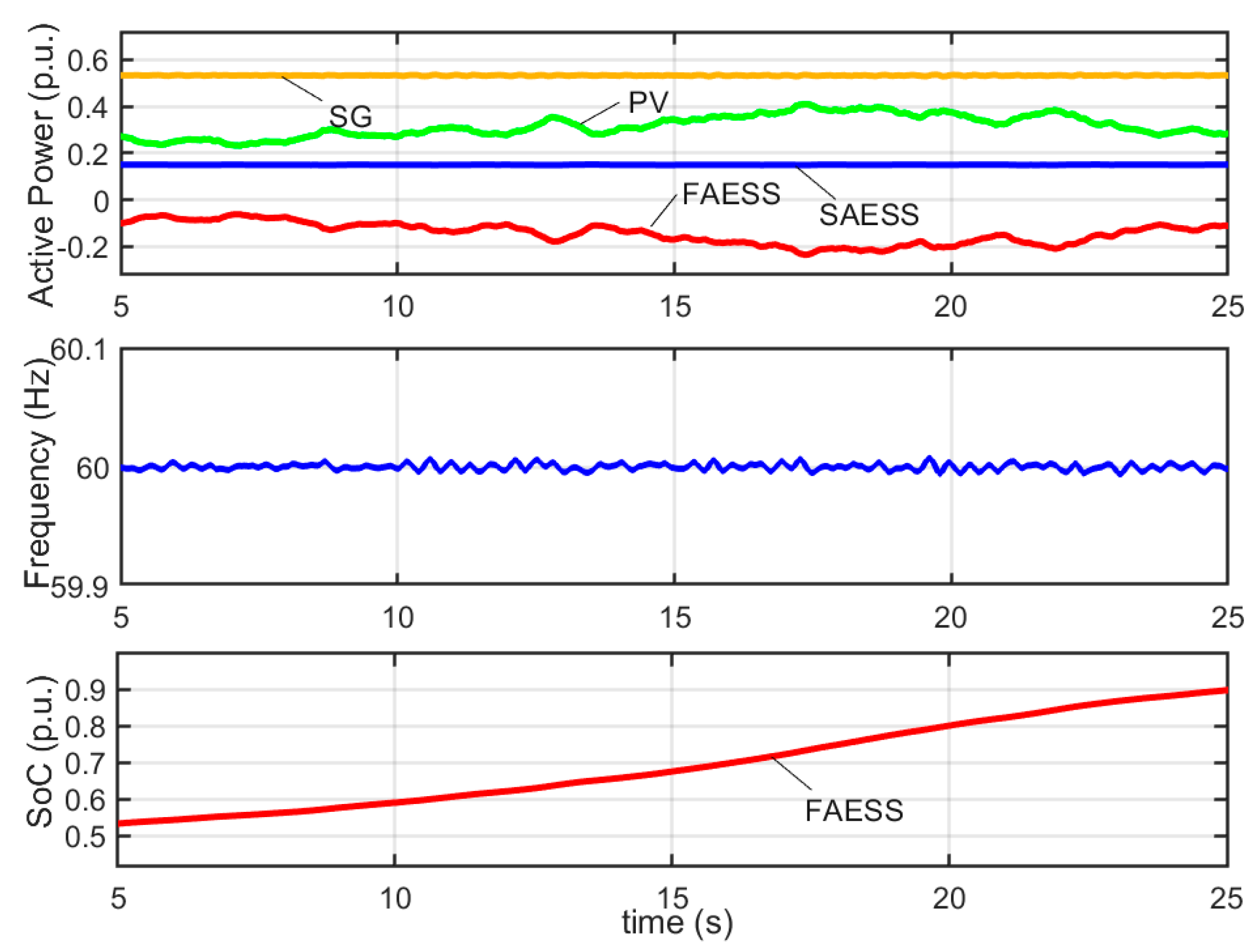
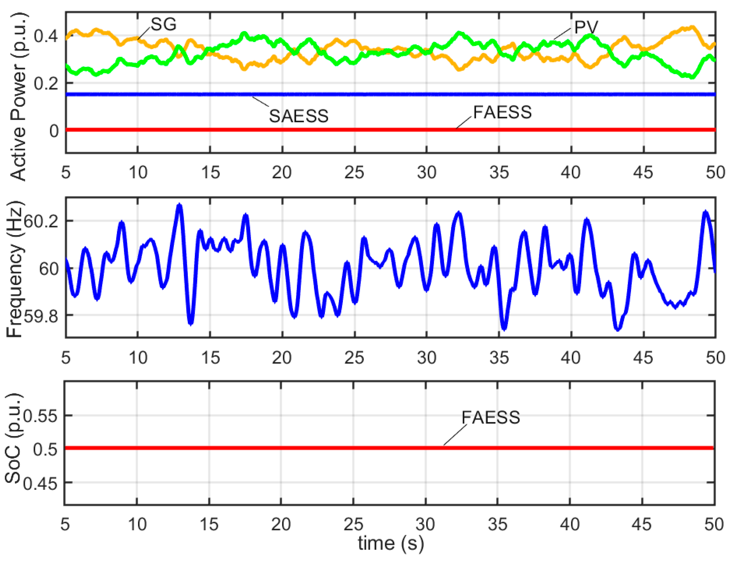
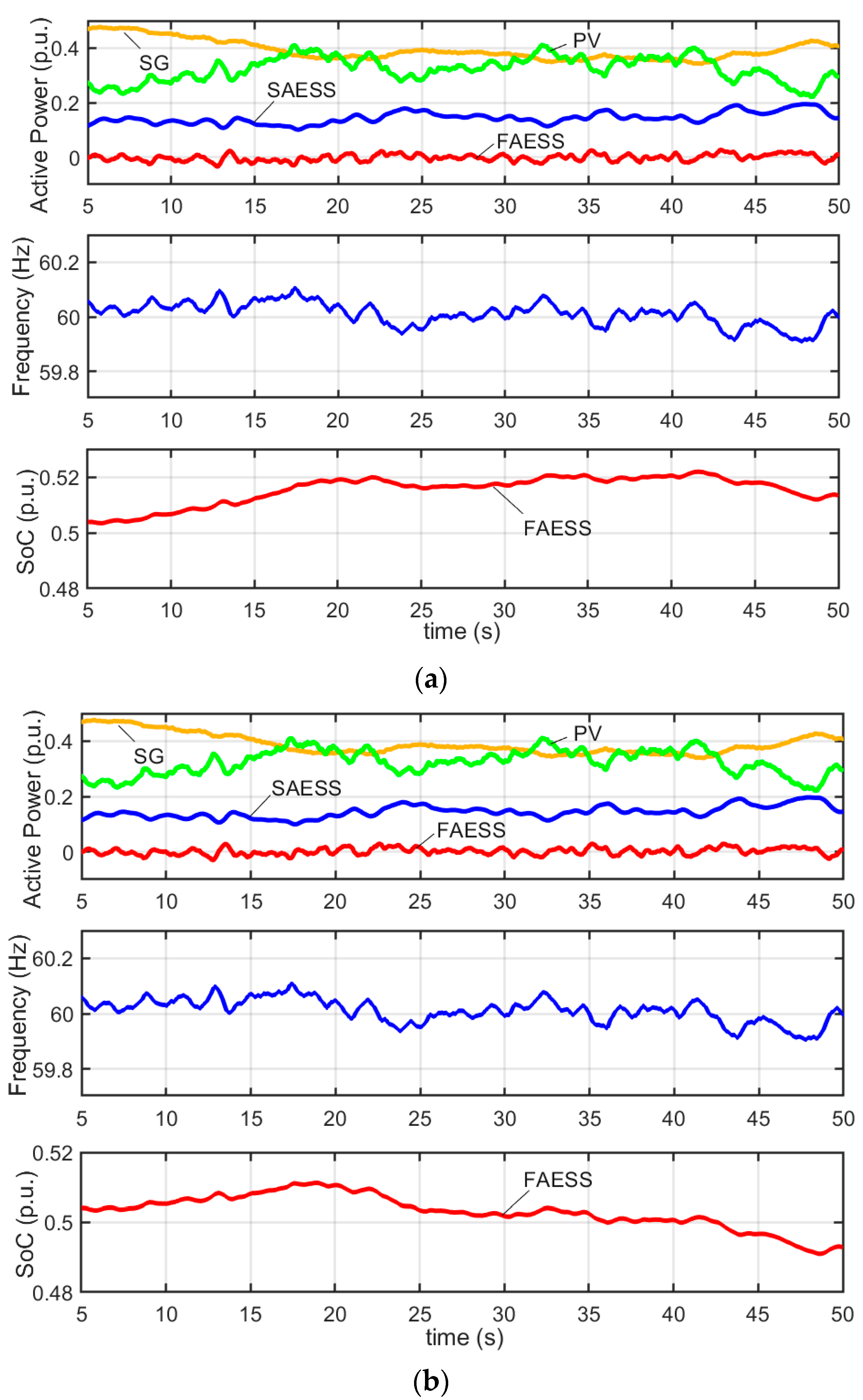
4.2. Simulation Test of Hybrid ESS-Based VSM under Renewable Generation Fluctuation

The power network under test is sketched in Figure 17. This case considers AC-coupled hybrid ESS in Figure 4c, with parameters in Table 2. The connecting impedances are also set at 0.05 p.u. The parameters of FAESS is identical to the lithium titanite battery used in Section 4.1. The energy capacity of SAESS is 320 kWh and the DC voltage is 960 V. This is realized by assembling 80 cells of 12 V lead–acid batteries and then having three groups in parallel. The photovoltaic generator is synchronized with the grid using PLL and operating in MPPT control mode. Comparison of traditional power system control with ESS-based VSM control is conducted.
First, FAESS adopting constant voltage and frequency (or short for “VF”) control under the master-slave control scheme is tested [35]. As illustrated in Figure 18, the FAESS picks up all the power mismatch, and frequency is controlled to be constant. Although the SAESS and SG have frequency support capability, their power is fixed around their references. The power reference of the FAESS is set to zero and implicitly managed by a higher-level dispatch, but the renewable power fluctuation will make the FAESS discharge in the given case, which will soon drain its energy given the small energy capacity (Enom = 6.8 p.u.·s) selected. Therefore, VF control under master-slave scheme requires the ESS have a high response speed and large energy capacity.
In Figure 19 where the ESS adopts grid-following control and the SG adopts PI frequency control, there is a large fluctuation in frequency and SG power. This also reflects the worsened frequency performance in the practical power system, with more uptakes of renewable generators and higher pressure placed on SG for frequency regulation.
In Figure 20a, we first consider FAESS with conventional VSM control parameters set as Hfa = 5 s and Dfa = 10 p.u., yet without energy recovery control. The rate of frequency fluctuation becomes smaller (59.9–60.1 Hz), but the SoC of FAESS deviates from its reference value 0.5 and continues increasing. In Figure 20b, both VSM control and SoC recovery control are adopted. Frequency performance is similar, and the SoC of FAESS remains approximately 0.5. The wear and tears of the SG are reduced, and the demand for response speed and energy capacity on FAESS are also lower than constant VF control.
Control performances in the above tests are summarized in Table 4. As revealed, VF controlled FAESS features the best frequency control performance, but the largest energy deviation. This is opposite, for ESS with solely grid-following control. The VSM-controlled ESS without energy recovery, behaves better in frequency, but there is energy deviation compared with grid-following case. With energy recovery control added, better SoC performance (controlled near 0.5) is achieved.

5. Limitations and Future Research Directions

The practical applications of the general ESS-based VSM may require the following considerations, namely the operating constraints of energy resources and fault treatment of VSM in the power system.

5.1. Operating Limitations of Renewable Energy Resources for VSM Implementation

In deriving the power–frequency dynamics in Section 3.1, the types of renewable energy resources are not specified, but uniformly considered as “negative load”. This is reasonable since only the frequency support of ESS-based VSM is concerned, especially in the small-scale power system. If frequency control is implemented on renewable energy resources, a similar analysis of the power–frequency dynamics can be conducted, by assuming a common system frequency and following the same procedure of multiple-machine analysis in the conventional power system [36,37]. This is feasible, for both grid-forming (VSM) controlled and grid-following grid-supporting renewable energy resources.
However, the constraints of renewable energy resources must be considered in practical VSM implementation [38]. For example, normally photovoltaic (PV) generation can only be shed in the over-frequency case to provide frequency support. Therefore, it is difficult to implement VSM on PV generators in case of low sunlight or at night. By contrast, wind turbine generator (WTG) can also contribute in the under-frequency case by releasing the kinetic energy in the turbine and generator rotor. Nevertheless, auxiliary control must be added so that the reduced rotor speed due to inertial and damping support remain within the allowed range [39,40,41]. Similarly, how to maintain VSM operation when wind turbine cannot rotate at very low wind speed is challenging. Though the capacitor on the DC bus of Type IV WTG can provide the energy needed for WTG at standstill, the power and energy capacity of the capacitor must be carefully selected. The procedure of analysis and design proposed in this work provide a guideline for future research.

5.2. Control and Stability of VSM in Faulty Conditions

This research focuses on the control of ESS-based VSM in normal mode. However, in practical applications, actions must be taken to deal with contingencies, such as faulty events in the system. For the faults located behind the breaker, the protection relay will normally trip the device off by opening the circuit breaker. If the fault is before the breaker, there may be fault ride-through requirement, such as low voltage ride through (LVRT), depending on the grid code, especially for large-capacity facilities [42].
LVRT strategies for grid-following converters, such as conventional renewable generators synchronized with PLL, have been extensively studied and validated in field, but it is still a challenge for grid-forming converter such as VSM, which needs further investigation into two key aspects [2,3,4,5,6]. (1) Current of VSM must be limited within the safe range in the faulty cases. As a voltage source intrinsically, VSM will experience overcurrent in the low-voltage or short-circuit fault, and may thus damage the converter or ESS associated with VSM, especially considering the overcurrent capability is smaller than conventional rotating generators [26]. There are no standard solutions at present, based on either software (for example, virtual impedance or saturation control) or hardware (overcurrent limiter or protection). (2) Research on transient stability should also be conducted to evaluate the stability performance during faults and provide guidelines for critical clearing time design [2]. This is more complex than conventional synchronous generator given the additional current limiting control introduced. Modified equal area criteria or Lyapunov energy function are two mainstream approaches for such studies.

6. Conclusions

A general ESS-based virtual synchronous machine with energy recovery control is introduced in this paper, which provides a general scheme of incorporating VSM into the conventional power system frequency regulation. Based on comprehensive theoretical analysis and comparative studies, the following conclusions are drawn.
(1) It is highlighted that the energy storage used for VSM application should meet the requirement of response speed and energy capacity in inertial and frequency support. A general control scheme, covering single ESS, hybrid ESS including FAESS and SAESS, as well as other ESS types and installation, is proposed for VSM implementation.
(2) The energy dissipation of VSM-controlled ESS is found to be reciprocal to the integral gain of frequency regulation, while proportional to virtual damping, virtual governor gain or their sum, depending on the ESS configuration. Such an energy amount is found to be at the second time scale, for example 6.8 p.u.·s in this article, which provides a guideline for storage sizing or distributed storage aggregation in VSM realization.
(3) With the proposed energy recovery control, ESS can maintain the original energy capacity for continuous VSM operation. A bandwidth separation rule for energy recovery control is proposed. Namely, the energy recovery bandwidth should fall between the bandwidth of secondary and tertial frequency control. Without energy recovery, the steady-state SoC of ESS-based VSM is larger than 20% in the test, which may soon incur degradation. The proposed energy recovery can maintain the SoC near the desired value 50%, without undermining frequency control performance.
It is recommended that further studies include VSM control for renewable energy resources considering the operating limitations, fault-ride-through strategy design, transient stability analysis and improvement for VSM in contingencies.

Author Contributions

Conceptualization, C.S.; methodology, C.S.; software, H.L.; validation, H.L.; formal analysis, X.Z.; data curation, H.L., C.S. and X.Z.; writing—original draft preparation, H.L., C.S. and J.W.; writing—review and editing, all authors; visualization, X.Z.; project administration, N.W.; funding acquisition, N.W. All authors have read and agreed to the published version of the manuscript.

Funding

This research is funded by the Beijing Institute of Precision Mechatronics and Controls. The project is supported by the School of Automation Science and Electrical Engineering, Beihang University, Beijing, China.

Data Availability Statement

We confirm that data will be made available on request.

Acknowledgments

We appreciate the guidance by Syed Qaseem Ali, the former team lead of Distribution and Generation Team at OPAL-RT Technologies Inc., Montreal, Canada, and the help of Jinling Qi from Harbin Institute of Technology in building the testbench.

Conflicts of Interest

The authors claim no conflict of interest.

References

  1. Sun, C.; Ali, S.Q.; Joos, G.; Bouffard, F. Design of Hybrid-Storage-Based Virtual Synchronous Machine with Energy Recovery Control Considering Energy Consumed in Inertial and Damping Support. IEEE Trans. Power Electron. 2022, 37, 2648–2666. [Google Scholar] [CrossRef]
  2. Rosso, R.; Wang, X.; Liserre, M.; Lu, X.; Engelken, S. Grid-Forming Converters: Control Approaches, Grid-Synchronization, and Future Trends—A Review. IEEE Open J. Ind. Appl. 2021, 2, 93–109. [Google Scholar] [CrossRef]
  3. Shi, K.; Song, W.; Xu, P.; Liu, R.; Fang, Z.; Ji, Y. Low-voltage ride-through control strategy for a virtual synchronous generator based on smooth switching. IEEE Access 2017, 6, 2703–2711. [Google Scholar] [CrossRef]
  4. Qoria, T.; Gruson, F.; Colas, F.; Kestelyn, X.; Guillaud, X. Current limiting algorithms and transient stability analysis of grid-forming VSCs. Electr. Power Syst. Res. 2020, 189, 106726. [Google Scholar] [CrossRef]
  5. Rokrok, E.; Qoria, T.; Bruyere, A.; Francois, B.; Guillaud, X. Transient Stability Assessment and Enhancement of Grid-Forming Converters Embedding Current Reference Saturation as Current Limiting Strategy. IEEE Trans. Power Syst. 2022, 37, 1519–1531. [Google Scholar] [CrossRef]
  6. Cheng, H.; Shuai, Z.; Shen, C.; Liu, X.; Li, Z.; Shen, Z.J. Transient Angle Stability of Paralleled Synchronous and Virtual Synchronous Generators in Islanded Microgrids. IEEE Trans. Power Electron. 2020, 35, 8751–8765. [Google Scholar] [CrossRef]
  7. D’Arco, S.; Suul, J.A.; Fosso, O.B. Control system tuning and stability analysis of Virtual Synchronous Machines. In Proceedings of the 2013 IEEE Energy Conversion Congress and Exposition, Denver, CO, USA, 15–19 September 2013; pp. 2664–2671. [Google Scholar]
  8. Mo, O.; D’Arco, S.; Suul, J.A. Evaluation of Virtual Synchronous Machines with Dynamic or Quasi-Stationary Machine Models. IEEE Trans. Ind. Electron. 2017, 64, 5952–5962. [Google Scholar] [CrossRef] [Green Version]
  9. Sun, C.; Bouffard, F.; Chen, J. A Generalized Multi-filter-based Oscillation Damping Approach for Droop-controlled Inverters in Microgrid. In Proceedings of the 2018 IEEE Power & Energy Society General Meeting (PESGM), Portland, OR, USA, 5–10 August 2018; pp. 1–5. [Google Scholar]
  10. Shadoul, M.; Ahshan, R.; AlAbri, R.S.; Al-Badi, A.; Albadi, M.; Jamil, M. A Comprehensive Review on a Virtual-Synchronous Generator: Topologies, Control Orders and Techniques, Energy Storages, and Applications. Energies 2022, 15, 8406. [Google Scholar] [CrossRef]
  11. Abuagreb, M.; Allehyani, M.F.; Johnson, B.K. Overview of Virtual Synchronous Generators: Existing Projects, Challenges, and Future Trends. Electronics 2022, 11, 2843. [Google Scholar] [CrossRef]
  12. Yap, K.Y.; Sarimuthu, C.R.; Lim, J.M.-Y. Virtual Inertia-Based Inverters for Mitigating Frequency Instability in Grid-Connected Renewable Energy System: A Review. Appl. Sci. 2019, 9, 5300. [Google Scholar] [CrossRef] [Green Version]
  13. Qing-Chang, Z. Synchronverter without a Dedicated Synchronization Unit. In Power Electronics-Enabled Autonomous Power Systems: Next Generation Smart Grids; IEEE: Piscataway, NJ, USA, 2020; pp. 107–124. [Google Scholar]
  14. Chen, J.; Zeng, Q.; Li, G.; Xin, Y.; Li, L.; Wang, P. Deviation-Free Frequency Control of MMC-MTDC Converter Based on Improved VSG. In Proceedings of the 2019 4th IEEE Workshop on the Electronic Grid (eGRID), Xiamen, China, 11–14 November 2019; pp. 1–5. [Google Scholar]
  15. Hirase, Y.; Sugimoto, K.; Sakimoto, K.; Ise, T. Analysis of Resonance in Microgrids and Effects of System Frequency Stabilization Using a Virtual Synchronous Generator. IEEE J. Emerg. Sel. Top. Power Electron. 2016, 4, 1287–1298. [Google Scholar] [CrossRef]
  16. Gong, X.; Wang, X. A novel Koopman-inspired method for the secondary control of microgrids with grid-forming and grid-following sources. Appl. Energy 2023, 333, 120631. [Google Scholar] [CrossRef]
  17. Zhang, W.; Yan, X. Equivalence Analysis of Virtual Synchronous Machines and Frequency-Droops for Inertia Emulation in Power Systems with Converter-Interfaced Renewables. J. Electr. Eng. Technol. 2020, 15, 1167–1175. [Google Scholar] [CrossRef]
  18. Zhang, B.; Zhang, X.; Yang, E.; Yan, X. Economic analysis and configuration design for the energy storage unit of photovoltaic virtual synchronous generator based on the inertia support and primary frequency control. Int. J. Electr. Power Energy Syst. 2022, 134, 107349. [Google Scholar] [CrossRef]
  19. Shi, M.; Chen, H.; Zhang, C.; Mei, F.; Fang, J.; Miao, H. A virtual synchronous generator system control method with battery SOC feedback. In Proceedings of the 2018 2nd IEEE Conference on Energy Internet and Energy System Integration (EI2), Beijing, China, 20–22 October 2018; pp. 1–4. [Google Scholar]
  20. Yuan, C.; Liu, C.; Yang, D.; Zhou, R.; Tang, N. Transient Characteristics and Physical Constraints of Grid-Tied Virtual Synchronous Machines. J. Power Electron. 2018, 18, 1111–1126. [Google Scholar]
  21. Ma, Y.; Cao, W.; Yang, L.; Wang, F.; Tolbert, L.M. Virtual synchronous generator control of full converter wind turbines with short-term energy storage. IEEE Trans. Ind. Electron. 2017, 64, 8821–8831. [Google Scholar] [CrossRef]
  22. Fang, J.; Li, H.; Tang, Y.; Blaabjerg, F. Distributed power system virtual inertia implemented by grid-connected power converters. IEEE Trans. Power Electron. 2017, 33, 8488–8499. [Google Scholar] [CrossRef] [Green Version]
  23. Fang, J.; Tang, Y.; Li, H.; Li, X. A Battery/Ultracapacitor Hybrid Energy Storage System for Implementing the Power Management of Virtual Synchronous Generators. IEEE Trans. Power Electron. 2018, 33, 2820–2824. [Google Scholar] [CrossRef]
  24. Sun, C.; Ali, S.Q.; Joos, G.; Bouffard, F. Virtual synchronous machine control for low-inertia power system considering energy storage limitation. In Proceedings of the 2019 IEEE Energy Conversion Congress and Exposition (ECCE), Baltimore, MD, USA, 29 September–3 October 2019; pp. 6021–6028. [Google Scholar]
  25. Liu, C.; Fang, J. Analysis and Design of Inertia for Grid-Tied Electric Vehicle Chargers Operating as Virtual Synchronous Machines. Appl. Sci. 2022, 12, 2194. [Google Scholar] [CrossRef]
  26. Ebrahimi, H.; Yazdaninejadi, A.; Golshannavaz, S. Transient stability enhancement in multiple-microgrid networks by cloud energy storage system alongside considering protection system limitations. IET Gener. Transm. Distrib. 2022, 17, 1816–1826. [Google Scholar] [CrossRef]
  27. Shim, J.W.; Verbič, G.; Zhang, N.; Hur, K. Harmonious integration of faster-acting energy storage systems into frequency control reserves in power grid with high renewable generation. IEEE Trans. Power Syst. 2018, 33, 6193–6205. [Google Scholar] [CrossRef]
  28. Christiansen, C.; Murray, B.; Conway, G.; Chambers, C. Energy Storage Study: Funding and Knowledge Sharing Priorities; AECOM: Sydney, Australia, 2015. [Google Scholar]
  29. Luo, X.; Wang, J.; Dooner, M.; Clarke, J. Overview of current development in electrical energy storage technologies and the application potential in power system operation. Appl. Energy 2015, 137, 511–536. [Google Scholar] [CrossRef] [Green Version]
  30. Zhong, Q.-C.; Wang, Y.; Ren, B. Connecting the home grid to the public grid: Field demonstration of virtual synchronous machines. IEEE Power Electron. Mag. 2019, 6, 41–49. [Google Scholar] [CrossRef]
  31. Fernández-Guillamón, A.; Gómez-Lázaro, E.; Muljadi, E.; Molina-García, Á. Power systems with high renewable energy sources: A review of inertia and frequency control strategies over time. Renew. Sustain. Energy Rev. 2019, 115, 109369. [Google Scholar] [CrossRef] [Green Version]
  32. Sun, C.; Ali, S.Q.; Joos, G. Opportunities and Challenges in Electric Vehicle Fleet Charging Management. In Electric Vehicle Integration in a Smart Microgrid Environment; CRC Press: Boca Raton, FL, USA, 2021; pp. 33–71. [Google Scholar]
  33. Zhang, H.; Xiang, W.; Lin, W.; Wen, J. Grid forming converters in renewable energy sources dominated power grid: Control strategy, stability, application, and challenges. J. Mod. Power Syst. Clean Energy 2021, 9, 1239–1256. [Google Scholar] [CrossRef]
  34. Sun, C.; Joos, G.; Bouffard, F. Identification of low-frequency oscillation mode and improved damping design for virtual synchronous machines in microgrid. IET Gener. Transm. Distrib. 2019, 13, 2993–3001. [Google Scholar] [CrossRef]
  35. Sun, C.; Joos, G.; Ali, S.Q.; Paquin, J.N.; Rangel, C.M.; Al Jajeh, F.; Novickij, I.; Bouffard, F. Design and real-time implementation of a centralized microgrid control system with rule-based dispatch and seamless transition function. IEEE Trans. Ind. Appl. 2020, 56, 3168–3177. [Google Scholar] [CrossRef]
  36. Unruh, P.; Nuschke, M.; Strauß, P.; Welck, F. Overview on grid-forming inverter control methods. Energies 2020, 13, 2589. [Google Scholar] [CrossRef]
  37. Liu, B.; Zhao, J.; Huang, Q.; Milano, F.; Zhang, Y.; Hu, W. Nonlinear Virtual Inertia Control of WTGs for Enhancing Primary Frequency Response and Suppressing Drivetrain Torsional Oscillations. IEEE Trans. Power Syst. 2021, 36, 4102–4113. [Google Scholar] [CrossRef]
  38. Sun, C.; Ali, S.Q.; Joos, G.; Bouffard, F. Improved VSG Control for Type-IV Wind Turbine Generator Considering Operation Limitations. In Proceedings of the 2019 IEEE Energy Conversion Congress and Exposition (ECCE), Baltimore, MD, USA, 29 September–3 October 2019; pp. 2085–2091. [Google Scholar]
  39. Zhang, J.; Zhang, B.; Li, Q.; Zhou, G.; Wang, L.; Li, B.; Li, K. Fast Frequency Regulation Method for Power System With Two-Stage Photovoltaic Plants. IEEE Trans. Sustain. Energy 2022, 13, 1779–1789. [Google Scholar] [CrossRef]
  40. Radaelli, L.; Martinez, S. Frequency Stability Analysis of a Low Inertia Power System with Interactions among Power Electronics Interfaced Generators with Frequency Response Capabilities. Appl. Sci. 2022, 12, 11126. [Google Scholar] [CrossRef]
  41. Tamrakar, U.; Shrestha, D.; Maharjan, M.; Bhattarai, B.P.; Hansen, T.M.; Tonkoski, R. Virtual Inertia: Current Trends and Future Directions. Appl. Sci. 2017, 7, 654. [Google Scholar] [CrossRef] [Green Version]
  42. IEEE Std 1547-2018 (Revision of IEEE Std 1547-2003); IEEE Standard for Interconnection and Interoperability of Distributed Energy Resources with Associated Electric Power Systems Interfaces. IEEE: Piscataway, NJ, USA, 2018; pp. 1–138.
Figure 1. Diagram of general VSM based on various forms of energy storage.
Applsci 13 08059 g001
Figure 2. Power rating and discharge time of energy storage (adapted from [28]).
Applsci 13 08059 g002
Figure 3. Comparison of energy and power density of energy storage (adapted from [29]).
Applsci 13 08059 g003
Figure 4. Topology of VSM implementation based on ESS. (a) Single ESS configuration (lithium–titanite battery as an example); (b) DC-coupled hybrid ESS; (c) AC-coupled hybrid ESS.
Applsci 13 08059 g004
Figure 5. Diagram of general ESS-based VSM with energy recovery control.
Applsci 13 08059 g005
Figure 6. Example power network studied.
Applsci 13 08059 g006
Figure 7. Simplified diagram of frequency regulation in the power system with SG and VSM.
Applsci 13 08059 g007
Figure 8. Diagram of the simplified SoC recovery control for ESS-based VSM.
Applsci 13 08059 g008
Figure 9. Bode plots of primary frequency, secondary frequency and SoC recovery control.
Applsci 13 08059 g009
Figure 10. Illustration of the bandwidth of frequency and the SoC control loops.
Applsci 13 08059 g010
Figure 11. Root locus as the governor control gain kp,sa increases from 5 p.u. to 30 p.u., with (blue) and without (red) FAESS adopting VSM control.
Applsci 13 08059 g011
Figure 12. Flowchart for design of general ESS-based VSM.
Applsci 13 08059 g012
Figure 13. Power network to test the VSM based on a single ESS.
Applsci 13 08059 g013
Figure 14. Simulation results for synchronous generator solely serving the loads. The waveforms show that the power of synchronous generator (PSG) balances the total load, and the frequency nadir is low and there is oscillation.
Applsci 13 08059 g014
Figure 15. Simulation results after adding single ESS-based VSM without energy recovery control. (a) frequency integral gain (ki,SG = 10 p.u.). The waveforms show the dynamics of synchronous generator power (PSG), the power component of VSM in inertial and damping support (PHD), virtual governor control (PGov) and the total power (PVSM). There is steady-state energy deviation. (b) Frequency integral gain (ki,SG = 5 p.u.). The steady-state energy deviation is approximately twice the amount in (a).
Applsci 13 08059 g015
Figure 16. Simulation results after adding the single ESS-based VSM. (a) Energy recovery control kp,e = 0.4 and ki,e = 0.002. The waveforms show the dynamics of synchronous generator power (PSG), the power component of VSM in inertial and damping support (PHD), virtual governor control (PGov) and the total power (PVSM). The energy is restored in steady state. (b) Energy recovery control kp,e = 1 and ki,e = 0.5. There are oscillations in all the waveforms.
Applsci 13 08059 g016
Figure 17. Power network to test the VSM based on AC-coupled hybrid ESS.
Applsci 13 08059 g017
Figure 18. Power, frequency and SoC dynamics when FAESS adopts VF control. The waveforms show that the frequency is fixed near 60 Hz, but the SoC of FAESS keeps increasing.
Applsci 13 08059 g018
Figure 19. The control performance when all ESS adopt purely grid-following control. The waveforms show that frequency fluctuation is large due to the PV generation variation.
Applsci 13 08059 g019
Figure 20. The control performance when FAESS and SAESS adopt the proposed VSM control. (a) Without SoC energy control. The waveforms show that the SoC of FAESS deviates from the desired value 0.5 (b) With SoC energy control applied to FAESS. The waveforms show that the SoC of FAESS is controlled near 0.5.
Applsci 13 08059 g020
Table 1. Summary of Some Typical research on ESS-based VSM.
Main FeaturesMain LimitationsTypical References
Ideal-source-based VSMEnergy resources on DC side not considered.[13,14,15,16,17]
Single-ESS-based VSMThe energy variation of ESS not analyzed.[10,11,12]
ESS-based VSM with SoC-limit triggered energy recoveryThe energy variation of ESS not quantified.
The energy reserve is small near the SoC limit.
The event trigger control may incur abrupt change.
[19]
Short-term ESS integrated with wind-turbine generator with SoC set-point controlThe energy variation of ESS not quantified.
The impact of SoC setpoint control on frequency regulation not considered.
The PI parameters of SoC setpoint control depends on rotor speed.
[21]
DC-coupled hybrid ESS including a supercapacitor and a batteryThe energy variation of ESS and thus energy recovery control not analyzed.[23]
Table 2. Parameters of the tested system.
ParametersValuesParametersValues
Base Voltage fref60 HzBase power320 kVA
Base voltage Vac (LL-RMS)600 VEnom6.8 p.u.·s (or 0.6 kWh)
Power rating of ESS1 p.u.SoCref of ESS0.5
TVSM0.3 sHVSM5 s
kp,VSM15 p.u.DVSM10 p.u.
kp,e0.4 p.u.ki,e0.002
Power rating of SG1 p.u.HSG2.5 s
DSG0TSG0.3 s
kp,SG15 p.u.ki,SG5 p.u.
Table 3. Control performance for different control of a single ESS and synchronous generator.
Devices and Key Control ParametersFrequency Nadir after the DisturbanceOscillation BehaviorSteady-State SoC Variation of ESS
SG only57.98 Hz, 0.19 s afterPeriod: 0.94 s;
Cycles: 2
N/A
SG and ESS, without SoC recovery Hfa = 5 s, Dfa = 10 p.u.,
ki,sg = 5 p.u.
59.35 Hz, 0.39 s afterTrivial0.066 p.u.
Hfa = 5 s, Dfa = 10 p.u.,
ki,sg = 10 p.u.
59.35 Hz, 0.39 s afterTrivial0.013 p.u.
SG and ESS, with SoC recoveryHfa = 5 s, Dfa = 10 p.u.,
kp,e = 0.4, ki,e = 0.002
59.34 Hz, 0.38 s afterTrivial0 p.u.
Hfa = 5 s, Dfa = 10 p.u.,
kp,e = 1, ki,e = 0.5
59.34 Hz, 0.38 s afterPeriod: 12 s; UndampedN/A
Table 4. Comparison of frequency performance in the power system with renewable generators for ESS with different control options.
Devices and Key Control ParametersFrequency VariationSoC Deviation of FAESS
FAESS adopts VF control, no SAESSAlmost constantSoC increases from 0.5 to 0.9 within 20 s
All ESS with PLL synchronization and no frequency supportMaximum ±0.22 Hz fluctuationKept at 0.5
Hybrid ESS adopts VSM control, without SoC recoveryMaximum ±0.1 Hz fluctuationMean SoC increases to 0.51 within 45 s
Hybrid ESS adopts VSM control, with SoC recoveryMaximum ±0.1 Hz fluctuationMean SoC near 0.5 within 45 s
Disclaimer/Publisher’s Note: The statements, opinions and data contained in all publications are solely those of the individual author(s) and contributor(s) and not of MDPI and/or the editor(s). MDPI and/or the editor(s) disclaim responsibility for any injury to people or property resulting from any ideas, methods, instructions or products referred to in the content.

