Abstract
The aim of this work is to assess the crystalline structure modification of an SLM Co-Cr-W dental alloy, veneered with two different ceramics, by means of X-ray diffraction (XRD), atomic force microscopy (AFM), and scanning electron microscopy, coupled with energy-dispersive spectroscopy (SEM-EDS). Ten identical plates were fabricated using SLM and were subsequently subjected to ceramic veneering. Following the repeated firing of the ceramic layers, carried out at temperatures exceeding 900 °C, new crystalline phases and variations in the crystallite sizes in the SLM Co-Cr-W dental alloy used for the substructure were detected via XRD. The two veneering ceramics showed significant differences in their behavior, beginning with the first firing, accompanied by structural changes. AFM micrographs and histograms of the surface heights over the whole scanned area of the samples showed that the surface of the Co-Cr-W dental alloy is strongly affected by the repeated firings necessitated by the ceramic firing process, a finding in accordance with the XRD results. The SEM investigation revealed that the different firing parameters had an impact on the alloy, the ceramic microstructure, and the surface quality. The differences in the chemical composition of the ceramics, highlighted by EDS, are reflected in their behavior. The crystalline alloy structure is influenced by the repeated firings of the ceramic layers.
1. Introduction
Casting alloys have been an important part of prosthodontic treatment for more than a century [1]. Initially, gold alloys were preferred for this purpose because of their biocompatibility and ease of use. As the price of gold increased substantially, manufacturers focused on less expensive alternatives such as Au-Ag-Pd and Pd-Ag alloys [2], followed by non-precious-metal dental alloys, such as the Fe-Cr-Ni, Ni-Cr, Co-Cr, and Ti alloys. Because of the allergenic potential of Ni-based alloys, currently, Co-Cr dental alloys are most commonly used for dental applications [3].
Co-Cr alloys are biocompatible materials, with high strength, good wear resistance, fatigue resistance, and corrosion resistance, along with a relatively affordable price; they are suitable for crown and bridge substructures, partial skeletal denture frameworks, and implants. Other elements are frequently added to improve the mechanical properties of the material, for example, Mo and W, which contribute to solid solution strengthening [4].
Co-Cr alloys are rather difficult to process using a traditional casting technique because of the manual manufacturing steps involved, leading to potentially low accuracy and satisfactory quality. Computer-aided design and computer-aided manufacturing (CAD/CAM), either subtractive or additive, offers the possibility of overcoming the disadvantages of the casting process [5,6,7].
The subtractive CAD/CAM technique used for dental applications allows the software-controlled mechanical milling of material blanks in order to obtain parts of a certain geometry [8]. Because the blanks are produced under high industrial standards, this reduces any flaws and pores, compared to the traditional manufacturing methods [9]. The subtractive method has the advantage of using homogenous materials, but its major drawbacks result from material loss and high costs.
In order to overcome these disadvantages, additive CAD/CAM procedures have been introduced. Also known as 3D printing, this process addresses the drawbacks of subtractive manufacturing in the CAM step. In this case, the prosthetic appliances are fabricated by layering the materials, instead of milling, and this process enables the manufacture of polymeric materials and alloys, as well as ceramics [10].
When considering the 3D printing of dental alloys, the most widely used technologies employ powder bed fusion (PBF): selective laser sintering (SLS), selective laser melting (SLM), and electron beam melting (EBM) [11], which share common basic principles. They involve a heat source that is used to consolidate the metallic powder, forming a 3D object by means of layer-by-layer deposition according to a CAD file, using a printer. Nevertheless, each technology has unique and special features, characteristics, capabilities, and limitations [12].
In SLS, the process consists of melting the edges of the grains, while in SLM and EBM, the metal powder is fully melted. Different modalities are used to achieve the melting point [9]. SLS uses a high-power laser to fuse small particles of the powder-form material, heated just below the melting point. As the laser beam moves, the material is being solidified. After each layer’s solidification, the powder bed is lowered by one layer of thickness, and the emerging empty space is filled with new powder material; this process is repeated until completion [12,13]. Unfortunately, parts fabricated by SLS are characterized by poor surface quality and high porosity [14].
SLM aims to produce highly dense objects using CO2 or fiber lasers (Nd:YAG or Yb:YAG) [15]. In SLM, the raw powder material is fully melted by the laser beam, resulting in selective melt pools, which, after re-solidification, turn into fully dense parts (>99% density, compared to 70% in SLS). The melting process can be adjusted by varying the wavelength, laser source, and power. Nevertheless, SLM production suffers from melt pool instabilities, which may lead to defects and imperfections such as surface roughness and the risk of internal porosity [9].
In both SLS and SLM, post-processing treatments, such as polishing and heat treatment, are needed to overcome the problems of poor surface quality and porosity [9]. However, compared to SLS, SLM is characterized by a lower occurrence of porosity and better surface quality [12].
EBM is very similar to SLM. It uses a focused electron beam in a vacuum environment to melt the metal powder by the transmission of kinetic energy [16].
Currently, SLM is the most widely used 3D printing technique for metal processing in dental applications [9]. Its capability to manufacture structures of high density and strength with complex shapes and geometries, the negligible waste of material, and the easy processing, with no need for distinct binders or melt phases, are just some of its advantages. The fact that the process is still expensive, compared to conventional manufacturing, and the need for post-processing are specific disadvantages [17].
Co-Cr alloys are the most commonly used materials for PBF in dental applications. Dental metallic substructures work under conditions of variable stress in a highly aggressive environment, the saliva; their durability is defined by their mechanical properties and corrosion resistance. SLM is often preferred, not only over the conventional casting method but even over CAD/CAM milling, as it enables the manufacturing of dental prosthetic restorations more quickly and less expensively. SLM substructures are characterized by good internal fitting, the necessity for nominal adaptation, and ceramic bond strength [18].
2. Background of the Study
Because of the distinct manufacturing differences between casting, which implies the complete melting and overheating of the alloy, the milling of a prefabricated metal block, and the PBF of a fine metallic powder, large differences in the microstructural characteristics of the substructure are to be anticipated [19].
SLM leads to a different microstructural evolution compared to that formed in casting and milling. SLM alloy microstructures show finer grains when compared to casting alloys [18,20], as well as to milled ones [21]; they offer better mechanical properties and similar ceramic bond strength compared to casting alloys [22,23].
The microstructure of SLM Co-Cr prosthetic restorations greatly influences their mechanical properties [16,24], revealing variations due to the beam parameters and scan strategies [25,26].
In the case of crowns and bridges, the subsequent ceramic veneering of the metallic substructure necessitates the repeated firing of the different ceramic layers at temperatures over 900 °C [27].
Comparative analysis of the specific properties of metallic substructures obtained by SLM is still limited; thus, the effect of the SLM technique on the mechanical, electrochemical, microstructural, and other properties of the resulting products is still not extensively documented [19,24,28].
Most of the available studies concerning the influence of repeated firings on porcelain-fused-to-metal SLM Co-Cr restorations are mainly focused on the evaluation of their marginal and/or internal fit [7,29,30], or on testing the metal–ceramic bond strength [31,32,33,34,35,36,37].
Altintas et al. reported that repeated firing has a negative effect on the passive fit of metallic substructures that had been obtained via laser sintering [38], while other studies showed no significant influence of repeated firings on the marginal accuracy of SLM copings [39] or SLM crowns, exhibiting a marginal and internal accuracy that was comparable to those created using conventional production procedures [29].
The results of previously published studies that aimed to assess the alloy’s microstructure following simulated ceramic firing are also quite controversial.
Rylska et al. aimed to compare the microstructure of cast, milled, and 3D-printed alloys that were subjected to porcelain firing from the corrosion point of view, and concluded that SLM alloys exhibited the highest corrosion resistance due to the microstructural homogeneity of the oxide layers and the fact that the specimens retained their structure [40].
Zeng et al. aimed to assess a Co-Cr-Mo alloy, fabricated by SLM, from the standpoint of its corrosion behavior before and after ceramic firing. The ceramic firing altered the microstructure, microhardness, and X-ray photoelectron spectroscopy (XPS) results, although it had no significant influence on the corrosion behavior of the SLM alloy [41].
Xin et al. examined the microstructure and surface composition of an SLM Co-Cr dental alloy before and after ceramic firing, using metallographic microscopy, X-ray diffraction (XRD), and XPS. Although the ceramic firing resulted in an alteration of the alloy microstructure, the samples still exhibited a compact and homogeneous structure, and no significant differences were detected in the surface composition of the specimens after firing [42].
Jabbari et al. compared the microstructure, porosity, mechanical properties, ion release, and tarnish resistance of Co-Cr alloys developed via conventional casting, milling, SLM, and the milling of soft metal, concluding that the porcelain firing did not affect their microstructural characteristics [43].
Li et al., after an investigation of the ceramic bond strength of Co-Cr alloys processed by casting, milling, and SLM, concluded that their microstructures were not affected by ceramic firing [34].
Lin et al. tested two types of alloys: a high Cr-Mo alloy without Be and a low Cr-Mo alloy with Be, examined via XPS and XRD. Both alloys exhibited new phases in their microstructure and showed significant changes in hardness after firing. In addition, there was a slight increase in CrO(x) on the surface of the Be-free alloy, and increased Mo-Ni was also observed on the surface of both alloys. The ceramic firing process changed the alloys’ hardness, microstructure, and surface composition [44].
The aim of this work is to assess the crystalline structure modification of the metallic substructure of an SLM Co-Cr-W dental alloy veneered with ceramics, following repeated firings of the ceramic layers that were carried out at temperatures exceeding 900 °C, employing XRD. Analyses using atomic force microscopy (AFM) and scanning electron microscopy, coupled with energy-dispersive spectroscopy (SEM-EDS), complemented the research. Two feldspathic veneering ceramics with different firing parameters were used, in order to determine if any difference in the alloy’s behavior could be detected.
3. Materials and Methods
3.1. Materials and Sample Preparation
A total of 10 identical square plates were fabricated using SLM. The dimensions of the plates were 5 × 5 mm, with a thickness of 0.3 mm. These dimensions were chosen so that the samples would fit into the diffractometer tray and would correspond to the clinical requirements for the metallic substructure thickness of a metal–ceramic crown. The design was defined using the exocad basic (Darmstadt, Germany) software.
Remanium star CL Co-Cr-W alloy (powder), Type 5 (Dentaurum, Ispringen, Germany) was used for the SLM fabrication of metal plates. The nominal chemical composition of the alloy is given in Table 1 [45].

Table 1.
Chemical composition of remanium star CL Co-Cr-W alloy (as given by the manufacturer).
The Mlab 200R SLM (GE Additive, West Chester, PA, USA) machine was used for the fabrication of the metal plates. The Mlab 200R SLM machine uses a laser system of 200 W, with a scanning speed of 7 m/s and a focus diameter of approximately 75 µm. The printing process takes place under inert gas, shielded from external influences. The printing planes are perpendicular to the SLM building direction.
After finishing the printing procedure, the plates were removed from the printing tray using a micromotor disc and were then sandblasted using a sandblasting machine standard for dental use.
Subsequently, each of the 10 plates was subjected to ceramic veneering, as described in Table 2 and Table 3. To ensure the flatness of the samples, the ceramics were layered while keeping the same thickness of 1.5 mm, which matches the clinical requirements.

Table 2.
Ceramic firing parameters of the P1 samples.

Table 3.
Ceramic firing parameters of the P2 samples.
Two different feldspathic ceramics from two different manufacturers (P1 and P2), with different firing parameters, were used for veneering the Co-Cr-W alloy plates. IPS InLine (Ivoclar, Schaan, Liechtenstein) Basic Kit was used for 5 plates (P1) and the Baot Metal Ceramic Standard Kit (Baot, China) for the other 5 plates (P2). Only one side of the samples was layered with ceramic (denoted as C), while the other side was left unlayered, consisting of as-3D-printed Co-Cr-W dental alloy (denoted as M). The firing parameters used were chosen according to the manufacturer’s instructions (Table 2 and Table 3). The veneering and the firing were carried out by the same dental technician (C.S.). Each of the samples was placed in the center of the ceramic furnace.
The chemical composition of IPS InLine (Ivoclar, Schaan, Liechtenstein), the ceramic layers of Dentin, Enamel (Transpa), Glaze, and Opaquer (according to the manufacturer), is given in Table 4 and is described as consisting of a glassy matrix and leucite crystals [46].

Table 4.
Chemical composition of IPS InLine (Ivoclar, Schaan, Liechtenstein) ceramic layers (as given by the manufacturer).
The BAOT’s ceramic powder constituents are, according to the literature: “silicon oxide, aluminum oxide, potassium oxide, sodium oxide, zirconia, calcium oxide, boron oxide, etc. It is mainly introduced from potassium feldspar, and through catalysis, it crystallizes repeatedly to form garnet crystals” [47].
However, the chemical compositions of the alloy and the ceramics, as determined by EDS, are presented in the results section.
3.2. Microstructure Assessment
3.2.1. X-ray Diffraction (XRD)
XRD in the angular range of 2θ = 20–60° was carried out using the XRD X’Pert PRO MPD diffractometer (PANalytical, Almelo, The Netherlands), using Cu-K radiation, and was operated at 40 kV and 30 mA. Both sides of the samples (the C and the M sides) were analyzed and the obtained diffraction patterns were indexed according to the inorganic crystal structure database (ICSD).
3.2.2. Atomic Force Microscopy (AFM)
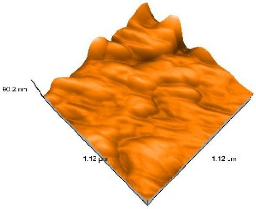
The surface characterization of the Co-Cr-W dental alloy, depending on the number of firings, was further evaluated with an atomic force microscope, the Easy Scan 2 Advanced Research (Nanosurf AG, Liestal, Switzerland). The values of the roughness parameters, namely, root-mean-square height, Sq (nm), and peak-to-valley height, Sy (nm), were quantified. The surface topography was provided using AFM three-dimensional images with a scan size of 1.12 µm × 1.12 µm, taken in contact mode.
3.2.3. Scanning Electron Microscopy, Coupled with Energy-Dispersive Spectroscopy (SEM-EDS)
The microstructure (×3000 magnification) and chemical composition SEM-EDS investigations were carried out using an Inspect S system (FEI Company, Hillsboro, OR, USA).
4. Results
4.1. X-ray Diffraction
The XRD pattern of the deposited ceramic layers is shown in Figure 1. In accordance with the evolution of XRD patterns for P1, after the first firing (2_P1_C), of the opaquer layer, all diffraction peaks were indexed as KAlSi2O6 (JCPDS no. 01-085-1626) and ZrO2 (JCPDS no. 01-078-0047) at percentages of 58% and 42%, respectively (Figure 1a).
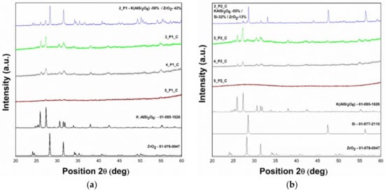
Figure 1.
(a) X-ray diffraction (XRD) patterns of P1_C samples at room temperature; (b) XRD patterns of P2_C samples at room temperature.
The second firing determined the complete formation of a KAlSi2O6 phase with a tetragonal symmetry, and no formation of impurity phases was observed in the 3_P1_C sample. The third and fourth firings (4_P1_C and 5_P1_C) only decreased the crystalline quality of the KAlSi2O6 phase (Figure 1a).
P2 showed a different behavior during the first firing, following the depositing of the opaquer, additionally highlighting the Si crystalline phase. The KAlSi2O6:ZrO2:Si crystalline phase distribution is 55%:13%:32% (Figure 1b). After the second firing, KAlSi2O6 became the unique crystalline phase. Subsequent deposition decreased the crystalline structure. In the case of the 5_P2_C sample, when subjected to the fourth firing, the ordered structure of the ceramic layer was destroyed, becoming amorphous. Thus, the Si content has a certain impact on the ceramic’s behavior.
As shown in Figure 2 and Figure 3, the structure of the Co-Cr-W dental alloy is strongly affected by the repeated firings of the ceramic layers, especially by the first firing of the opaquer, which takes place at 930 °C for P1, and at 940 °C for P2 (samples 2_P1_M and 2_P2_M, respectively). The modification of the crystalline quality is clearly reflected in the intensity of the diffraction peaks.
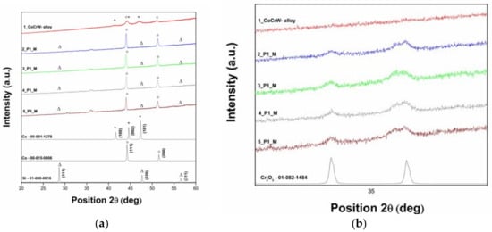
Figure 2.
(a) XRD patterns of the P1_M samples at room temperature; (b) enlargement of the indexed XRD peaks of the Cr2O3 crystalline phase.
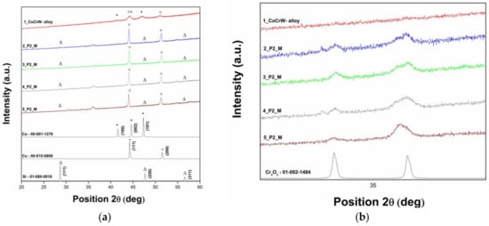
Figure 3.
(a) XRD patterns of the P2_M samples at room temperature; (b) enlargement of the indexed XRD peaks for the Cr2O3 crystalline phase.
The intact 3-D-printed samples of 1_Co-Cr-W_alloy display a low, crystalline, ordered structure based on the mixture of two polymorphs of cobalt metal with hexagonal symmetry (JCPDS no. 00-001-1278, space group: P63/mmc) and cubic symmetry (JCPDS no. 00-015-0806, space group: Fm3m). The structure was transformed into a high crystalline cubic structure after the first firing, regardless of the ceramic used for veneering.
The subsequent firings caused a different evolution of the M samples, depending on the ceramic used and variations in the firing temperature. In the case of P1, the structural changes of the dental alloy were moderate, almost as if the high crystalline cubic structure is a stabilizing influence. Conversely, in the case of P2, the crystalline structure of the dental alloy continued to change abruptly (Figure 4a–c). All P1_M and P2_M samples also revealed the presence of the Si crystalline phase (cubic, JCPDS no. 01-080-0018, space group: F-43m).
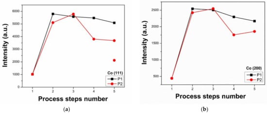
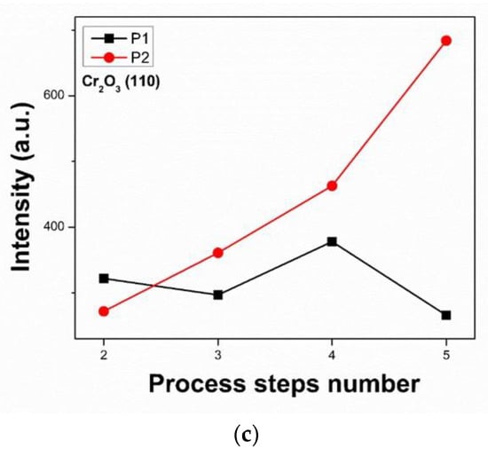
Figure 4.
The evolution of the diffraction peak intensity in the function of the number of firings: (a) (111) crystal plane of Co; (b) (200) crystal plane of Co, and (c) (110) crystal plane of Cr2O3.
Furthermore, a new crystalline phase of Cr2O3 with rhombohedral symmetry (JCPDS no. 01-082-1484, space group: R-3c) developed during the ceramic deposition process (Figure 2b and Figure 3b). According to Table 5, P1 favored the chromium oxidation of the dental alloy at up to 5.3% of (110) relative intensity, in contrast to the 15.65% value in the case of P2. The relative intensity for the (110) crystal plane of Cr2O3 was obtained by dividing the absolute intensity of this peak by the absolute intensity of the most intense peak corresponding to the (111) crystal plane of Co, then converting it to a percentage.

Table 5.
The evolution of the relative intensity for the (110) crystal plane of Cr2O3 after each firing.
To further analyze whether chromium oxidation is a surface or bulk process, the Cr2O3 layer was removed by polishing. The XRD pattern revealed that there was no Cr2O3 phase, highlighting the fact that chromium oxidation occurs only at the surface of the alloy, with the red dot representing the intensity of the crystallographic planes after polishing (Figure 4a). The low crystalline ordered structure and the lower intensity of the planes of the polished sample, compared with the unpolished sample, highlight the fact that the structural transformation of the dental alloy is a surface process (Figure 5).
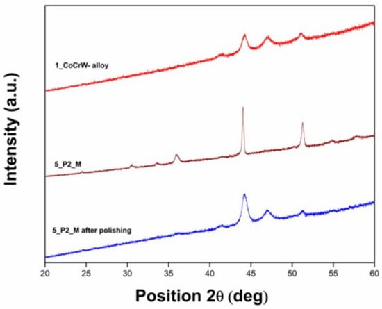
Figure 5.
XRD patterns of the 5_P2_M sample before and after polishing, at room temperature.
The Cr2O3 layer and the surface characteristics of these structural transformations play an important role in the bonding of the ceramic to the metallic substructure.
4.2. Atomic Force Microscopy
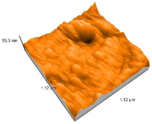
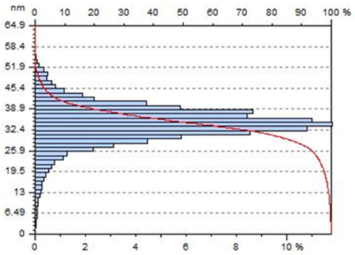
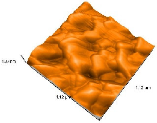
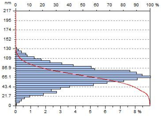
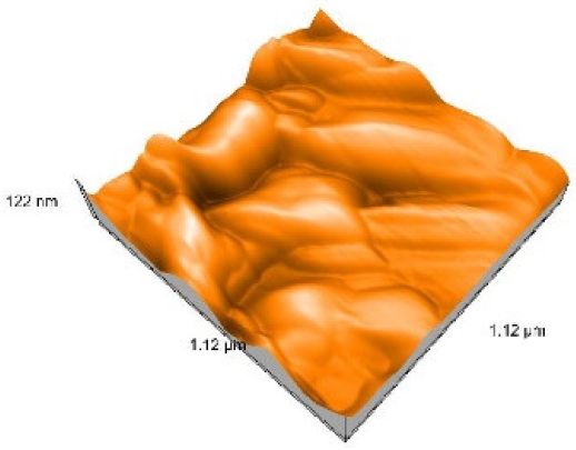
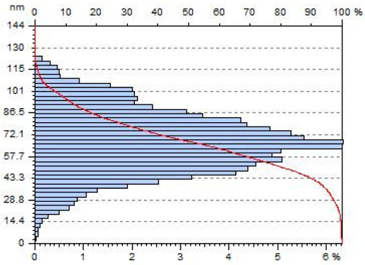
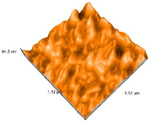
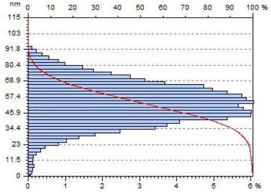
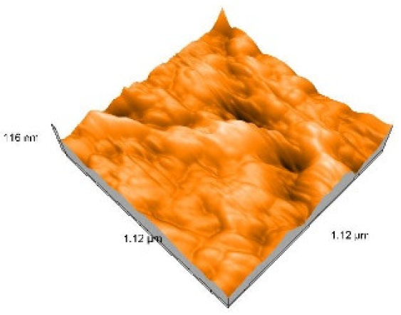
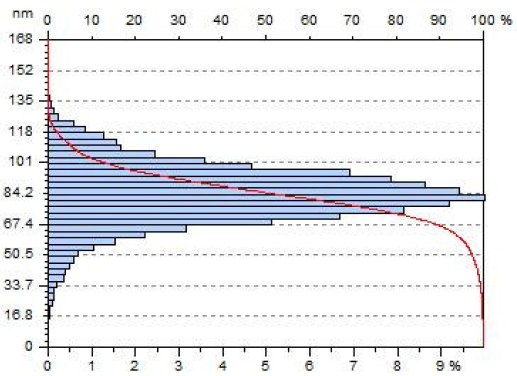
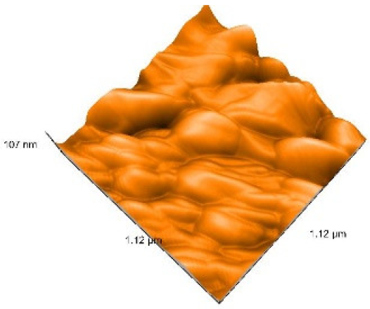
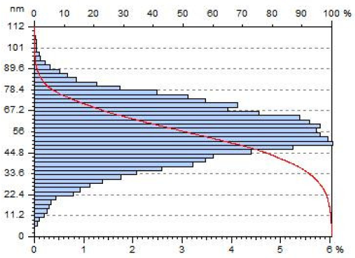
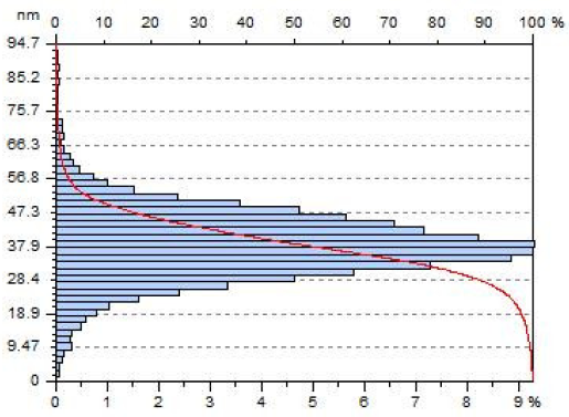
AFM micrographs and histograms of the surface heights over the entire scanned area of the samples are shown in Table 6. It can be seen that in both the SLM substructures, the surface height distribution is Gaussian, and no asymmetry is observed in the histograms, representing a homogenously rough surface. In accordance with the XRD results, the surface of the Co-Cr-W dental alloy was strongly affected by the repeated firings necessitated by the ceramic layering, especially by the first firing, this being highlighted by the height distribution. With a similar evolution of the crystalline structure (Figure 4a,b), the as-3-D-printed, Co-Cr-W dental alloy sample had a height distribution in the range of 6–52 nm, which abruptly increased to 6–130 nm for both the 2_P1_M and 2_P2_M samples. Thus, from the point of view of the surface heights, in the case of the first firing, temperature is primarily responsible for the structural modification. In contrast, the subsequent firings caused a different evolution of the M samples, depending on the ceramic used and its firing parameters. While for the 3_P1_M and 4_P1_M samples, a small diminution in the surface heights was highlighted, in the case of the 4_P2_M sample, the decrease is much more obvious, with values in the range of 5–75 nm. Based on the XRD results, this evolution of the Co-Cr-W dental alloy surface may be caused by the much more intensive development of the Cr2O3 layer in the 4_P2_M sample than in the 4_P1_M sample (Table 5). It can also be observed that, in the 2_P2_M, 3_P1_M, and 4_P1_M samples, the Gaussian “bells” are wider, which is an indication of a high number of roughness components on the tested area. In the case of the 2_P2_M and 4_P1_M samples, fewer but larger artifacts are evident in the micrographs, while the 3_P1_M micrograph reveals more numerous but smaller surface artifacts. The Sq and the Sy values of the M samples are summarized in Table 6 and correspond to the evolution of the crystalline structure of the Co-Cr-W dental alloy substructure during the repeated firings.

Table 6.
AFM micrographs, histograms of the surface heights, and Sq and Sy values after each firing.
4.3. Scanning Electron Microscopy, Coupled with Energy-Dispersive Spectroscopy
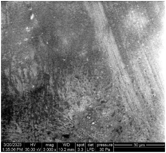
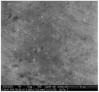
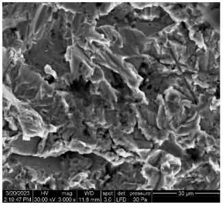
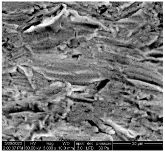
SEM images of the C and M sides of the samples that exhibited the most significant microstructural modifications, namely, 2_P1, 2_P2, 4_P1, and 4_P2, are shown in Table 7 and Table 8, along with the chemical composition, as determined by EDS. Table 8 also includes the results of SEM-EDS for the as-3-D-printed Co-Cr-W alloy.

Table 7.
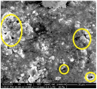
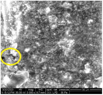
SEM (×3000 magnification) and EDS images of 2_P1_C, 2_P2_C, 4_P1_C, and 4_P2_C.

Table 8.
SEM (×3000 magnification) and EDS images of 1_P1_M, 2_P1_CM, 2_P2_M, 4_P1_M, and 4_P2_M.
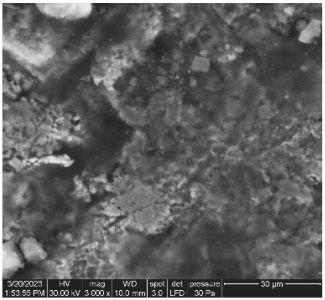
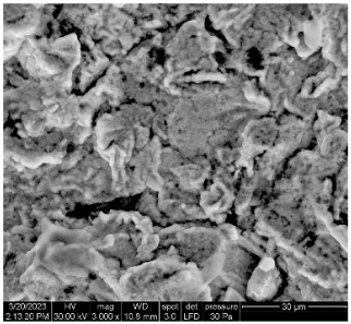
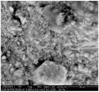
According to the SEM image, the surface of the 2_P1_C sample, layered with the opaquer and followed by firing at 930 °C, is characterized by high roughness and numerous defects, including the discontinuities and pores highlighted in the image. The observed porosity is probably related to opaquer condensation issues.
The SEM image of the 2_P2_C sample, layered with the opaquer following firing at 940 °C, reveals an improved surface roughness and texture, combined with a smaller volume fraction of surface defects, compared to the 2_P1_C sample fired at a lower temperature.
The SEM image of the surface of the 4_P1_C sample, with a multi-layered ceramic coating consisting of opaquer, dentin, and enamel, the subsequent firing at different temperatures (930 °C, 910 °C, and 900 °C) reveals a relatively smooth texture; no significant porosity can be observed.
The SEM image of the 4_P2_C sample with a multi-layered ceramic coating, consisting of opaquer, dentin, and enamel, followed by firing at different temperatures (940 °C, 930 °C, and 920 °C), exhibits a very smooth and homogeneous surface texture as a result of higher firing temperatures, while no significant surface defects, i.e., voids and microcracks, are detected.
The EDS analysis of the 2_P1_C sample revealed contents of Si, Al, K, Na, and Zr specific to the ceramic opaquer. In the case of the 2_P2_C sample, additional Ti and V contents were found, with the Zr content being much lower compared to that in the 2_P1_C sample, corresponding to the chemical composition of the opaquer as given by the manufacturer. The EDS chemical analysis of the 4_P1_C and 4_P2_C samples revealed contents of Si, Al, K, and Na that are specific for feldspathic ceramics. The EDS revealed a good correlation between the elemental composition and the crystalline phases, as highlighted by the XRD analysis.
SEM, coupled with the EDS results regarding the M sides of the investigated samples, revealed the samples’ surface characteristics following ceramic veneering at different firing temperatures. In the case of the as-3-D-printed sample (of Co-Cr-W dental alloy), the surface exhibited a rough texture, while the chemical composition provided by the EDS analysis was close to the alloy’s nominal composition, although possessing a slightly higher Si content. The other M samples also exhibited varying degrees of roughness, which is in accordance with the AFM results.
Moving on to the feldspathic ceramic-veneered samples, the opaquer layering (2_P1 and 2_P2), and the differently applied firing parameters certainly affected the surface quality and the chemical composition of the samples. The 2_P2_M sample fired at 940 °C exhibited a higher volume fraction of the ceramic products on the metal’s surface than the 2_P1_M sample, which was fired at a lower temperature (930 °C). This observation is also confirmed by the elemental analysis provided in Table 8, which, in the case of the 2_P2_M sample, revealed a much higher Si content: 12.6 wt %, instead of 4 wt %, and 3 wt % in the case of the 2_P1_M sample and the as-3D-printed Co-Cr-W alloy, respectively. Similarly, the 4_P1_M and 4_P2_M samples, which received a multi-layering ceramic coating using different firing conditions, exhibited surface roughness and chemical composition differences. The 4_P2_M sample, which was veneered at higher temperatures, was characterized by a higher volume fraction of ceramic microstructural constituents, as shown in the above SEM images, also exhibiting a larger Si content compared to the 4_P1_M sample, which was fired at lower temperatures. In particular, the 4_P1_M sample contained almost half the content of Si in comparison with the 4_P2_M samples.
Based on these microstructural observations, combined with the elemental analysis results, it can be concluded that the firing process parameters in both types of feldspathic ceramic coatings (opaque layered and multi-layered) can also have a significant effect on the surface characteristics and chemical composition of the M sides of the studied samples.
5. Discussion
The present study aims to evaluate the influence of ceramic veneering and of its firing parameters on the microstructure of SLM Co-Cr-W alloy, which was used as a substructure.
The results of the current study reveal that the microstructure of the SLM substructure has been affected by the ceramic layer firing procedure; much more significantly, the behavior of the alloy is strongly dependent on the firing temperature.
The ceramics themselves exhibited noticeably different behavior, by means of these structural changes, as a result of differences in the firing process.
The XRD analysis provided detailed information about the crystallographic structure, chemical composition, and phase identification, also yielding information on how the samples’ microstructures deviated from the initial structure when subjected to repeated firings.
The as-3-D-printed samples, 1_P1 and 1_P2, consisting of only Co-Cr-W dental alloy that was not layered and not fired, displayed a low, crystalline, ordered structure. The structure transforms into a high crystalline cubic structure after the first firing of the opaquer layer, regardless of the ceramic used for veneering. The modification of crystallinity quality is clearly reflected in the intensity of the diffraction peaks (Figure 2 and Figure 3).
The subsequent firing steps caused a different evolution of the alloy’s crystalline structure, depending on the ceramic used. In the case of P1, the structural changes were moderate, while in the case of P2, the crystalline structure of the dental alloy continued to change (Figure 4a–c). It is likely that the variations in the firing temperature (Table 1) between the two deposition processes were responsible for these differences.
The Cr2O3 crystalline phase, which developed during the repeated firings (Figure 3b and Figure 4b), indicated the different percentages of the (110) relative intensity: 5.3%, in the case of P1, and 15.65%, in the case of P2 (Table 5), once more emphasizing the behavioral differences. Chromium oxidation was proven to be a surface process (Figure 5), one that is quite normal and to be expected, as it plays an important role in the bonding of the ceramic to the metallic substructure. In the case of the metal–ceramic bond, chemical bonding is the predominant form; this refers to the reaction between the ceramic and the metal oxide layer, with the latter playing a fundamental role. Particularly in the case of base metal alloys, a certain saturation of both the metal and the ceramic with metal oxides occurs, ideally resulting in the formation of an oxide layer [37].
The dental Co-Cr alloys present oxidation surface morphologies and thicknesses that are known to be dependent upon the fabrication technique [34]. Much more significantly, differences in the alloy microstructures that are caused by the different manufacturing methods might also simultaneously change the nature of the surface oxidation, resulting in significantly modified adhesion behaviors [48].
The two veneering ceramics also showed different behaviors, starting with the first firing of the opaquer layer. It is common knowledge that the opaquer acts as an interface between the alloy and the ceramic and is also involved in the bonding between the two materials [49].
In the case of P1, the diffraction peaks were indexed as KAlSi2O6 (leucite), a typical crystalline phase related to the ceramic as a result of surface crystallization, along with ZrO2, a component of the opaquer. The second firing determines the complete formation of the KAlSi2O6 phase, with no formation of the impurity phases. The third and fourth firings only decreased the crystallinity quality of the KAlSi2O6 phase (Figure 1a).
P2 showed a different behavior during the first firing, additionally highlighting the Si crystalline phase (Figure 2). After the second firing, KAlSi2O6 became a unique crystalline phase. The subsequent firing steps determined the decrease in the crystalline structure until, in the case of the fourth firing, the ordered structure of the ceramic layer was destroyed, becoming amorphous; this indicates that the Si content may affect the behavior of the ceramic.
In accordance with the XRD results, the AFM surface analysis indicates that the Co-Cr-W dental alloy is strongly affected by the repeated firings necessitated by the ceramic layering, especially by the first firing (opaquer layer). Both P1 and P2 samples display a large increase in the surface roughness, which is evident in both Sq and Sy. The height distribution abruptly increases from 6–52 nm, for the as-3-D-printed, Co-Cr-W dental alloy sample, to 6–130 nm for both the 2_P1_M and 2_P2_M samples, which is similar to the evolution of the crystalline structure (Figure 4a,b). Thus, from the perspective of the surface heights, in the case of the first firing, the temperature was primarily responsible for the structural modification.
After the second firing, the roughness slightly decreased, followed by an increase during the subsequent firing steps. This behavior indicates that the firing process can cause inconsistent fluctuations in the surface roughness, depending on the firing step. It should be noted that this behavior was evident for both P1 and P2 samples. Based on the XRD results, the differences in the alloy surface can also be correlated with the development of the Cr2O3 layer, which occurs much more intensively in the 4_P2_M sample than in the 4_P1_M sample.
SEM-EDS investigation confirmed that the different firing parameters affected both the C and M sides of the samples, their surface characteristics, and their chemical composition. In terms of the C sides, the SEM-EDS analysis revealed that the application of the opaquer layer resulted in a rough surface with a relatively high volume fraction of pores and microcracks for both experimented firing temperatures of 930 °C (2_P1_C) and 940 °C (2_P2_C). However, the higher firing temperature (2_P2_C) resulted in a more homogeneous surface, with limited porosity.
The further application of the dentin + enamel ceramic layers (4_P1_C and 4_P2_C), resulted in a surface texture that was characterized by few (4_P1_C) or even by no surface discontinuities (4_P2_C), the latter being fired at higher temperatures (Table 7).
In the case of the M sides of the investigated samples, variable degrees of roughness may be observed, which is in accordance with the AFM results. The higher firing temperature of P2 led to a greater number of ceramic constituents on the samples’ M sides, which can clearly be observed in Table 8. The higher Si content, observed in both the opaquer (2_P2_C) and the multi-layered samples (4_P2_C) at higher firing temperatures, confirms the abovementioned finding.
The present study clearly indicates that the repeated firings and the firing temperature have a certain influence on the microstructure of the investigated samples. Our findings are in accordance with those of Zeng et al. [41] and Lin et al. [44], who reported that ceramic firing altered the microstructure of the SLM substructure. Much more significantly, Lin et al. [44] also detected new phase formation by means of XRD.
The study by Xin et al., which used XRD, XPS, and metallographic microscopy for determining the microstructure and surface composition of an SLM Co-Cr dental alloy before and after ceramic firing, demonstrated an alteration of the alloy microstructure but, nevertheless, concluded that the samples retained a compact and homogeneous structure, and no significant differences in the surface composition after firing were detected [42].
The present study is in opposition to the findings of Rylska et al. [40], Jabbari et al. [43], and Li et al. [34], which revealed no modification of the alloys’ microstructure or the surface composition following ceramic firing.
To our knowledge, the previously published studies aimed to assess the alloy’s microstructure following simulated ceramic firing, with the samples only being subjected to the firing protocol, but no ceramic layering was carried out. However, the results of the SEM-EDS investigation indicated that the ceramic itself, along with the firing process, are reflected in the alloy’s microstructure.
According to Tripathi et al., the firing temperature has a certain influence on ceramic structures, with the increasing firing temperature gradient being of the utmost importance. Their findings indicate that a higher firing temperature results in a surface characterized by less significant porosities, as shown by there being fewer peaks obtained by the XRD graphs [50]. This conclusion is in accordance with our results; the 4_P2_C sample, fired at higher temperatures, exhibited a smoother and more homogeneous surface texture, compared to the 4_P1_sample, as shown in the SEM images (Table 7). The XRD graphs (Figure 1) confirm this fact, revealing fewer peaks in the case of the 4_P2_C sample, compared to the 4_P1_C sample.
From a practical point of view, in the humble opinion of the authors, the conducted experiments provide an avenue for further investigation since several issues require a more detailed approach and further analysis.
The current study should be considered a pilot study and further investigation on increased sample size will be carried out. Increasing the sample size will boost the statistical power of the tests. Further investigations into the differences in ceramic composition and the firing parameters, which triggered their dissimilar behavior, should be carried out, as well as including an increased number of ceramic veneering products in the test.
6. Conclusions
Within the limitations of this study, the main conclusions are as follows:
- The microstructure of the SLM Co-Cr-W dental alloy was influenced by the repeated firings due to the use of ceramic veneering.
- New crystalline phases and variations in the crystallite size of the SLM Co-Cr-W dental alloy used for the substructure could be detected using XRD.
- The Cr2O3 crystalline phase was limited to the surface of the alloy, being involved in the metal–ceramic bond.
- The AFM surface analysis and SEM-EDS investigations confirmed the XRD results, indicating that the Co-Cr-W dental alloy is strongly affected by the repeated firings.
- The two veneering ceramics showed significant differences in their behavior, beginning at the first firing, which was accompanied by a complete structure change. The surface quality of the ceramic layering was improved by an increase in the firing temperature.
Author Contributions
Conceptualization, M.L.N., C.S. (Cosmin Sinescu) and M.R.; methodology, M.L.N., C.S. (Cosmin Sinescu) and M.R.; software, A.D.S.; validation, C.S. (Caius Stoian), M.M. and C.C.; investigation, M.M. and C.C.; resources, C.S. (Caius Stoian), M.M. and C.C.; data curation, A.D.S.; writing—original draft preparation, C.S. (Caius Stoian), L.C.A., M.M., A.A. and A.K.; writing—review and editing, L.C.A. and M.M.; supervision, M.M., C.S. (Cosmin Sinescu) and M.R.; project administration, M.L.N. All authors have read and agreed to the published version of the manuscript.
Funding
This research received no external funding.
Institutional Review Board Statement
Not applicable.
Informed Consent Statement
Not applicable.
Data Availability Statement
No new data were created or analyzed in this study. Data sharing is not applicable to this article.
Conflicts of Interest
The authors declare no conflict of interest.
References
- Anusavice, K.J. Phillips’ Science of Dental Materials, 11th ed.; Saunders Elsevier: St. Louis, MO, USA, 2003; pp. 564–565. [Google Scholar]
- Rosenstiel, S.F.; Land, M.F.; Fujimoto, J. Contemporary Fixed Prosthodontics, 4th ed.; Mosby Elsevier: St. Louis MO, USA, 2006; pp. 606–608. [Google Scholar]
- Shen, C.; Ralph Rawls, H.; Esquivel-Upshaw, J.F. Phillips’ Science of Dental Materials, 13th ed.; Elsevier: St. Louis, MO, USA, 2022; p. 171. [Google Scholar]
- Malayoglu, U.; Neville, A. Mo and W, as alloying elements in Co-based alloy: Their effects on erosion–corrosion resistance. Wear 2005, 259, 219–229. [Google Scholar] [CrossRef]
- Ardelean, L.; Reclaru, L.; Bortun, C.; Rusu, L.C. Assessment of dental alloys by different methods. In Superalloys; Aliofkhazraei, M., Ed.; IntechOpen: Rjeka, Croatia, 2015; pp. 141–170. [Google Scholar]
- Olakanmi, E.O.; Cochrane, R.F.; Dalgarno, K.W. A review on selective laser sintering/melting (SLS/SLM) of aluminium alloy powders: Processing, microstructure, and properties. Prog. Mater. Sci. 2015, 74, 401–477. [Google Scholar] [CrossRef]
- Ucar, Y.; Akova, T.; Akyil, M.S.; Brantley, W.A. Internal fit evaluation of crowns prepared using a new dental crown fabrication technique: Laser-sintered Co-Cr crowns. J. Prosthet. Dent. 2009, 102, 253–259. [Google Scholar] [CrossRef] [PubMed]
- Rekow, D. Computer-aided design and manufacturing in dentistry: A review of the state of the art. J. Prosthet. Dent. 1987, 58, 512–516. [Google Scholar] [CrossRef] [PubMed]
- Konieczny, B.; Szczesio-Wlodarczyk, A.; Sokolowski, J.; Bociong, K. Challenges of Co–Cr Alloy Additive Manufacturing Methods in Dentistry—The Current State of Knowledge (Systematic Review). Materials 2020, 13, 3524. [Google Scholar] [CrossRef]
- Tigmeanu, C.V.; Ardelean, L.C.; Rusu, L.C.; Negrutiu, M.L. Additive manufactured polymers in dentistry, current state-of-the-art and future perspectives—A review. Polymers 2022, 14, 3658. [Google Scholar] [CrossRef]
- Reclaru, L.; Ardelean, L.C. Alternative Processing Techniques for CoCr Dental Alloys. In Encyclopedia of Biomedical Engineering; Narayan, R., Ed.; Elsevier: Amsterdam, The Netherlands, 2019; pp. 1–15. [Google Scholar] [CrossRef]
- Papazoglou, E.L.; Karkalos, N.E.; Karmiris-Obratanski, P.; Markopoulos, A.P. On the Modeling and Simulation of SLM and SLS for Metal and Polymer Powders: A Review. Arch. Comput. Methods Eng. 2022, 29, 941–973. [Google Scholar] [CrossRef]
- Reclaru, L.; Ardelean, L.; Rusu, L.C.; Sinescu, C. Co-Cr material selection in prosthetic restoration: Laser sintering technology. Solid State Phenom. Adv. Mater. Struct. IV 2012, 216, 412–415. [Google Scholar] [CrossRef]
- Okazaki, Y.; Ishino, A.; Higuchi, S. Chemical, Physical, and Mechanical Properties and Microstructures of Laser-Sintered Co–25Cr–5Mo–5W (SP2) and W–Free Co–28Cr–6Mo Alloys for Dental Applications. Materials 2019, 12, 4039. [Google Scholar] [CrossRef]
- Yap, C.Y.; Chua, C.K.; Dong, Z.L.; Liu, Z.H.; Zhang, D.Q.; Loh, L.E.; Sing, S.L. Review of selective laser melting: Materials and applications. Appl. Phys. Rev. 2015, 2, 41101. [Google Scholar] [CrossRef]
- Murr, L.E.; Gaytan, S.M.; Ramirez, D.A.; Martinez, E.; Hernandez, J.; Amato, K.N.; Shindo, P.W.; Medina, F.R.; Wicker, R.B. Metal Fabrication by Additive Manufacturing Using Laser and Electron Beam Melting Technologies. J. Mater. Sci. Technol. 2012, 28, 1. [Google Scholar] [CrossRef]
- Dejene, N.D.; Lemu, H.G. Current status and challenges of powder bed fusion-based metal additive manufacturing: Literature review. Metals 2023, 13, 424. [Google Scholar] [CrossRef]
- Koutsoukis, T.; Zinelis, S.; Eliades, G.; Al-Wazzan, K.; Rifaiy, M.A.; Al Jabbari, Y.S. Selective Laser Melting Technique of Co-Cr Dental Alloys: A Review of Structure and Properties and Comparative Analysis with Other Available Techniques. J. Prosthodont. 2015, 24, 303–312. [Google Scholar] [CrossRef]
- Al Jabbari, Y.S.; Koutsoukis, T.; Barmpagadaki, X.; Zinelis, S. Metallurgical and interfacial characterization of PFM Co-Cr dental alloys fabricated via casting, milling or selective laser melting. Dent. Mater. 2014, 30, 79–88. [Google Scholar] [CrossRef] [PubMed]
- Zhou, Y.; Wei, W.; Yan, J.; Liu, W.; Li, N.; Li, H.; Xu, S. Microstructures and metal-ceramic bond properties of Co-Cr biomedical alloys fabricated by selective laser melting and casting. Mater. Sci. Eng. A 2019, 759, 594–602. [Google Scholar] [CrossRef]
- Han, X.; Sawada, T.; Schille, C.; Schweizer, E.; Scheideler, L.; Geis-Gerstorfer, J.; Rupp, F.; Spintzyk, S. Comparative analysis of mechanical properties and metal-ceramic bond strength of Co-Cr dental alloy fabricated by different manufacturing processes. Materials 2018, 11, 1801. [Google Scholar] [CrossRef] [PubMed]
- Wu, L.; Zhu, H.; Gai, X.; Wang, Y. Evaluation of the mechanical properties and porcelain bond strength of cobalt-chromium dental alloy fabricated by selective laser melting. J. Prosthet. Dent. 2014, 111, 51–55. [Google Scholar] [CrossRef]
- Wang, H.; Lim, J.Y. Metal-ceramic bond strength of a cobalt chromium alloy for dental prosthetic restorations with a porous structure using metal 3D printing. Comput. Biol. Med. 2019, 112, 103364. [Google Scholar] [CrossRef]
- Takaichi, A.; Suyalatu; Nakamoto, T.; Joko, N.; Nomura, N.; Tsutsumi, Y.; Migita, S.; Doi, H.; Kurosu, S.; Chiba, A.; et al. Microstructures and mechanical properties of Co-29Cr-6Mo alloy fabricated by selective laser melting process for dental applications. J. Mech. Behav. Biomed. 2013, 21, 67–76. [Google Scholar] [CrossRef]
- Jia, H.; Sun, H.; Wang, H.; Wu, Y.; Wang, H. Scanning strategy in selective laser melting (SLM): A review. Int. J. Adv. Manuf. Technol. 2021, 113, 2413–2435. [Google Scholar] [CrossRef]
- Tonelli, L.; Fortunato, A.; Ceschini, L. CoCr alloy processed by Selective Laser Melting (SLM): Effect of Laser Energy Density on microstructure, surface morphology, and hardness. J. Manuf. Process. 2020, 52, 106–119. [Google Scholar] [CrossRef]
- Wang, J.H.; Ren, J.; Liu, W.; Wu, X.Y.; Gao, M.X.; Bai, P.K. Effect of Selective Laser Melting Process Parameters on Microstructure and Properties of Co-Cr Alloy. Materials 2018, 11, 1546. [Google Scholar] [CrossRef] [PubMed]
- Qian, B.; Saeidi, K.; Kvetkova, L.; Lofaj, F.; Xiao, C.; Shen, Z. Defects-tolerant Co-Cr-Mo dental alloys prepared by selective laser melting. Dent. Mater. 2015, 31, 1435–1444. [Google Scholar] [CrossRef] [PubMed]
- Quante, K.; Ludwig, K.; Kern, M. Marginal and internal fit of metal–ceramic crowns fabricated with a new laser melting technology. Dent. Mater. 2008, 24, 1311–1315. [Google Scholar] [CrossRef] [PubMed]
- Witkowski, S.; Komine, F.; Gerds, T. Marginal accuracy of titanium copings fabricated by casting and CAD/CAM techniques. J. Prosthet. Dent. 2006, 96, 47–52. [Google Scholar] [CrossRef]
- Akova, T.; Ucar, Y.; Tukay, A.; Balkaya, M.C.; Brantley, W.A. Comparison of the bond strength of laser-sintered and cast base metal dental alloys to porcelain. Dent. Mater. 2008, 24, 1400–1404. [Google Scholar] [CrossRef]
- Xiang, N.; Xin, X.Z.; Chen, J.; Wei, B. Metal–ceramic bond strength of Co–Cr alloy fabricated by selective laser melting. J. Dent. 2012, 40, 453–457. [Google Scholar] [CrossRef]
- Revilla-Leon, M.; Gomez-Polo, M.; Park, S.H.; Barmak, A.B.; Ozcan, M. Adhesion of veneering porcelain to cobalt-chromium dental alloys processed with casting, milling, and additive manufacturing methods: A systematic review and meta-analysis. J. Prosthet. Dent. 2022, 128, 575–588. [Google Scholar] [CrossRef]
- Li, J.; Chen, C.; Liao, J.; Liu, L.; Ye, X.; Lin, S.; Ye, J. Bond strengths of porcelain to cobalt-chromium alloys made by casting, milling, and selective laser melting. J. Prosthet. Dent. 2017, 118, 69–75. [Google Scholar] [CrossRef]
- Iseri, U.; Ozkurt, Z.; Kazazoglu, E. Shear bond strengths of veneering porcelain to cast, machined and laser-sintered titanium. Dent. Mater. J. 2011, 30, 274–280. [Google Scholar] [CrossRef]
- Daou, E.E.; Ozcan, M. Evaluation of ceramic adherence to cobalt-chromium alloys fabricated by different manufacturing techniques. J. Prosthet. Dent. 2022, 128, 1364.e1–1364.e8. [Google Scholar] [CrossRef] [PubMed]
- Wang, H.; Feng, Q.; Li, N.; Xu, S. Evaluation of metal-ceramic bond characteristics of three dental Co-Cr alloys prepared with different fabrication techniques. J. Prosthet. Dent. 2016, 116, 916–923. [Google Scholar] [CrossRef] [PubMed]
- Altintas, M.A.; Akin, H. Effect of repetitive firing on passive fit of metal substructure produced by the laser sintering in implant-supported fixed prosthesis. J. Adv. Prosthodont. 2020, 12, 167–172. [Google Scholar] [CrossRef]
- Zeng, L.; Zhang, Y.; Liu, Z.; Wei, B. Effects of repeated firing on the marginal accuracy of Co-Cr copings fabricated by selective laser melting. J. Prosthet. Dent. 2015, 113, 135–139. [Google Scholar] [CrossRef]
- Rylska, D.; Januszewicz, B.; Sokołowski, G.; Sokołowski, J. Corrosion Resistance of Cr–Co Alloys Subjected to Porcelain Firing Heat Treatment—In Vitro Study. Processes 2021, 9, 636. [Google Scholar] [CrossRef]
- Zeng, L.; Xiang, N.; Wei, B. A comparison of corrosion resistance of cobalt-chromium-molybdenum metal ceramic alloy fabricated with selective laser melting and traditional processing. J. Prosthet. Dent. 2014, 112, 1217–1224. [Google Scholar] [CrossRef]
- Xin, X.Z.; Chen, J.; Xiang, N.; Gong, Y.; Wei, B. Surface characteristics and corrosion properties of selective laser melted Co-Cr dental alloy after porcelain firing. Dent. Mater. 2014, 30, 263–270. [Google Scholar] [CrossRef]
- Al Jabbari, Y.S.; Barmpagadaki, X.; Psarris, I.; Zinelis, S. Microstructural, mechanical, ionic release and tarnish resistance characterization of porcelain fused to metal Co–Cr alloys manufactured via casting and three different CAD/CAM techniques. J. Prosthodont. Res. 2019, 63, 150–156. [Google Scholar] [CrossRef]
- Lin, H.Y.; Bowers, B.; Wolan, J.T.; Cai, Z.; Bumgardner, J.D. Metallurgical, surface, and corrosion analysis of Ni-Cr dental casting alloys before and after porcelain firing. Dent. Mater. 2008, 24, 378–385. [Google Scholar] [CrossRef]
- Forstec. Available online: https://forstec.se/wp-content/uploads/2020/03/GEAP_Remanium-star_DS_EN_US_2_v1_0.pdf (accessed on 10 December 2022).
- Ivodent. Available online: https://ivodent.hu/__docs/777_b0862ae911ed1387c1f74aec2cc5a6c5.pdf (accessed on 10 December 2022).
- Distrident Plus. Available online: https://www.distridentplus.ro/baot-PFM-enamel-e1b (accessed on 10 December 2022).
- Serra-Prat, J.; Cano-Batalla, J.; Cabratosa-Termes, J.; Figueras-Àlvarez, O. Adhesion of dental porcelain to cast, milled, and laser-sintered cobalt-chromium alloys: Shear bond strength and sensitivity to thermocycling. J. Prosthet. Dent. 2014, 112, 600–605. [Google Scholar] [CrossRef]
- Jörn, D.; Neil Waddell, J.; Swain, M.V. The influence of opaque application methods on the bond strength and final shade of PFM restorations. J. Dent. 2010, 38, e143–e149. [Google Scholar] [CrossRef] [PubMed]
- Tripathi, A.; Bagchi, S.; Singh, J.; Gaurav, V.; Pal Singh Negi, M. Effect of different firing temperatures on structural changes in porcelain. J. Prosthodont. 2018, 27, 290–298. [Google Scholar] [CrossRef] [PubMed]
Disclaimer/Publisher’s Note: The statements, opinions and data contained in all publications are solely those of the individual author(s) and contributor(s) and not of MDPI and/or the editor(s). MDPI and/or the editor(s) disclaim responsibility for any injury to people or property resulting from any ideas, methods, instructions or products referred to in the content. |
© 2023 by the authors. Licensee MDPI, Basel, Switzerland. This article is an open access article distributed under the terms and conditions of the Creative Commons Attribution (CC BY) license (https://creativecommons.org/licenses/by/4.0/).
