Article

Finite-Time Height Control of Quadrotor UAVs

1
School of Automation, Beijing Institute of Technology, Beijing 100081, China
2
Aerospace Shenzhou Aerial Vehicle Ltd., Tianjin 300160, China
3
Tianjin Key Laboratory of Intelligent Unmanned Swarm Technology and System, School of Electrical and Information Engineering, Tianjin University, Tianjin 300072, China
*
Author to whom correspondence should be addressed.
Appl. Sci. 2023, 13(13), 7914; https://doi.org/10.3390/app13137914
Submission received: 25 April 2023 / Revised: 12 June 2023 / Accepted: 25 June 2023 / Published: 6 July 2023
(This article belongs to the Special Issue New Technology for Autonomous UAV Monitoring)

Abstract

:
The quadrotor Unmanned Aerial Vehicle (UAV) belongs to an open-loop unstable nonlinear system, which also has the characteristics of underdrive, strong coupling and external disturbance. In the height control of quadrotor UAVs, the traditional sliding mode control (SMC) and PID methods cannot quickly and effectively eliminate disturbance effects caused by gust, aerodynamic drag and other factors, which indicates that the quadrotor UAV cannot return to its predetermined trajectory. To this end, this paper proposes a dual closed-loop finite-time height control method for the quadrotor UAV. The proposed method is able to estimate and compensate for the disturbance in the height control and make up for the lack of anti-disturbance ability in the control process. More specifically, a finite-time Extended State Observer (ESO) and a finite-time super-twisting controller are designed for the velocity control system to compensate for the total disturbance and track the rapidly changing expected signal. An integral sliding mode controller is designed for the height control system. Simulation results show that the proposed method can reduce the chattering phenomenon of traditional SMC and improve both control accuracy and convergence speed.

1. Introduction

Quadrotor UAVs have many advantages, including vertical takeoff and landing, low cost and flexibility [1,2,3]. Nowadays, there are many specific applications of quadrotor UAVs, such as rescue, surveillance, inspection, aerial photography, mapping and logistics [4,5,6]. Therefore, stable hovering, rapid maneuvering and safe operations are very important requirements for quadrotor UAVs in order to realize these functions [7]. However, the quadrotor UAV belongs to an open-loop unstable nonlinear system, which is underactuated and has strong coupling and vulnerability to external disturbances [8,9]. Especially in the height control of the quadrotor UAV, there are not only disturbances, such as gust and aerodynamic drag, but also control challenges caused by load change and body vibration [10,11]. Based on the terminal sliding mode, a novel control strategy is proposed to solve the position and attitude tracking problem of quadrotor UAVs under external disturbances and system uncertainties [10]. In [11], a cascade control method with an Active Disturbance Rejection Control (ADRC) algorithm [12] is designed to control the out-of-water motion of amphibious multirotor UAVs under complex external disturbances. Therefore, a robust height control strategy with anti-disturbance ability is of great significance for maintaining flight safety of quadrotor UAVs.
For the height control problem of quadrotor UAVs, experts and scholars have developed SMC, PID control, optimal control and back-stepping control methods [13]. However, these methods are mainly based on the idea of passive anti-disturbance, and some methods even require accurate disturbance models, which creates difficulties in compensating for disturbances in practice [14]. The extended state observer (ESO) can estimate disturbances without prior knowledge to actively compensate in the controller [15]. Therefore, the ESO has been increasingly used and developed in various fields of control [16,17,18]. Note that traditional SMC methods slow down the convergence speed of the system, and peak effects may occur in the large gain of traditional ESOs [19]. Compared to asymptotically stable control methods, finite-time control methods ensure that the system error tends to zero within a finite time [20,21,22]. Although the convergence time is related to the initial state, the finite-time method not only accelerates the convergence speed of the system but also alleviates the peak effect of the ESO, thereby achieving a real-time estimation ability for rapidly changing disturbances [23].
Recently, many other novel height controllers have been designed for multirotor UAVs, considering disturbances in different scenarios. A combined model reference adaptive control law is given for height control loop of a multirotor [24]. An adaptive nonsingular fast terminal SMC strategy is introduced to realize height control for quadrotors with variable mass and external disturbance [25]. Based on the back-stepping method, a fractional order sliding mode controller is proposed to attenuate wind disturbance and effects of variations in both loads and momentums of inertia [26]. In [27], a novel adaptive multilayer neural dynamic-based controller is used to control the height of a multirotor UAV. A multiple-model adaptive controller architecture is designed for height control of a quadrotor when transporting an unknown constant load [28]. It is known from [29] that a fault-tolerant control algorithm can control the altitude of quadrotor UAVs even in the presence of possible multiple actuator faults and modeling uncertainties. These height controllers have achieved satisfying results, but discussions about using ESOs to further improve control performance have been limited.
In this paper, a dual closed-loop control method is designed to estimate and compensate for disturbances in the height control of quadrotor UAVs and improve the anti-disturbance ability. The dynamic model of quadrotor UAVs in the height direction is divided into an inner-loop velocity control system and an outer-loop height control system. A finite-time ESO is developed for the inner-loop velocity system to estimate disturbances in real time, and a finite-time super-twisting controller is constructed to improve the convergence speed and robustness of the system. An integral sliding mode controller is designed for the outer-loop height system to improve control accuracy. The main contributions of this paper are summarized as follows:
I. 
A dual closed-loop control frame is proposed with a finite-time super-twisting controller in the inner loop and an integral sliding mode controller in the outer loop for a quadrotor UAV.
II. 
An upper bound of convergence time is introduced for a finite-time ESO, which is applied in the inner loop to assist the finite-time super-twisting controller in estimating disturbances.
III. 
With excellent robustness, an integral sliding mode controller is designed to both generate a desired height velocity signal for the inner loop and reject disturbances of the outer loop.
In this paper,  | |  and  , respectively, represent absolute values and Euclid norms. The superscript  T  represents the transposition of the matrix and  I  represents the identity matrix with the appropriate dimension.  sign ( )  is a common symbolic function.  λ max { E }  and  λ min { E } , respectively, represent the largest eigenvalue and the smallest eigenvalue of the matrix  E .

2. Height Dynamic Model of Quadrotor UAV

According to [21], a height dynamic model of the quadrotor UAV as shown in Figure 1 is established in the following form as
z ¨ t = cos θ t cos ϕ t U 1 t + ξ t g
where  z ( t )  represents the actual flight height of the quadrotor UAV,  θ ( t )  and  ϕ ( t )  represent the current pitch angle and roll angle, respectively,  U 1 ( t )  is the total lift force,  ξ t  represents the external disturbance, and  g  is the gravitational acceleration and can be approximated as 9.8 m/s2. This scheme adopts the dual closed-loop design and divides the above height model into a height velocity inner loop and a height position outer loop.
Letting  x 1 ( t ) = z · ( t ) , the dynamics equation for the height velocity inner loop can be written as
x · 1 t = b 0 u t + ξ t g
where  b 0 u ( t ) = ( cos ( θ ( t ) ) cos ( ϕ ( t ) ) ) U 1 ( t ) b 0  is a positive adjustable parameter, and  u ( t )  is the control input.
To show the main results of this paper, the following lemma is presented. Note that the following lemma is used to promote follow-up analysis on convergence time of both the finite-time ESO and the finite-time super-twisting controller.
Lemma 1
([22]). For the system of  x · ( t ) = f ( x ( t ) ) , there are  f ( 0 ) = 0  and  x ( t ) R n .
  • If the scalar function  V ( x ( t ) )  satisfies  V · ( x ( t ) ) a V b ( x ( t ) ) , where  a > 0  and  0 < b < 1 , then the system is stable in the finite time and the converge time is calculated by  t s V ( 0 ) ( 1 b ) a ( 1 b ) .
  • If the scalar function  V ( x ( t ) )  satisfies  V · ( x ( t ) ) a 1 V ( x ( t ) ) a 2 V b ( x ( t ) ) , where  a 1 > 0 , a 2 > 0  and  0 < b < 1 , then the system is stable in the finite time and the converge time is calculated by  t m 1 a 1 ( 1 b ) ln a 1 V ( 0 ) ( 1 b ) + a 2 a 2 .

3. Inner-Loop Control Scheme Design

3.1. Finite-Time ESO Design

In this section, a finite-time ESO and a finite-time super-twisting controller are designed for the height velocity inner loop. Assume that the external disturbance  ξ t  in the formula is continuously differentiable and bounded. Letting  x 2 t = ξ t , the height velocity inner loop (2) of the quadrotor UAV is rewritten as
x · 1 ( t ) = b 0 u ( t ) + x 2 ( t ) g x · 2 ( t ) = ϖ ( t )
Here, where  ϖ ( t )  represents the derivative of  ξ t , and there exists a positive number  M  satisfying  ϖ ( t ) M . Define a new variable  ς 1 ( t ) = z 1 ( t ) x 1 ( t ) , and a finite-time ESO for the height velocity inner loop (2) is designed as
z · 1 ( t ) = z 2 ( t ) β 1 | ς 1 ( t ) | n sign ( ς 1 ( t ) ) β 2 ς 1 ( t ) + b 0 u g z · 2 ( t ) = β 3 | ς 1 ( t ) | n sign ( ς 1 ( t ) )
where  z 1 ( t )  and  z 2 ( t )  are the estimations of  x 1 ( t )  and  x 2 ( t ) , respectively,  ς 1 ( t )  is the observation error of  x 1 ( t ) β 1 β 2 , and  β 3  are the positive adjustable observer gains, and  n  is the exponential gain, which rests within (0, 1).
Letting  ς 2 ( t ) = z 2 ( t ) x 2 ( t ) , then for the inner loop, the observation error equation for the finite-time ESO (4) is
ς · 1 ( t ) = ς 2 ( t ) β 1 | ς 1 ( t ) | n sign ( ς 1 ( t ) ) β 2 ς 1 ( t ) ς · 2 ( t ) = β 3 | ς 1 ( t ) | n sign ( ς 1 ( t ) ) ϖ ( t )
For the observation error Equation (5), the stability proof of the finite-time ESO is given in the following.
Theorem 1.
Considering the height velocity inner loop (2) and the finite-time ESO (4), if the parameters satisfy  β 1 > 0 ,  β 2 > 0 ,  β 3 > 0  and  0 < n < 1 , then the observation error  ς 1 ( t )  and  ς 2 ( t )  will converge to a small neighborhood centered at the origin in finite time  T m . The convergence time is calculated by the following formula as
T m 2 λ max { L 1 } d 1 ln d 1 λ max { L 1 } V 1 ( 0 ) + d 2 λ max { L 1 } d 2 λ max { L 1 } .
where  L 1  is a positive definite symmetric matrix defined such that
L 1 = β 1 n + β 3 2 β 3 β 3 2
Proof of Theorem 1.
Construct a Lyapunov function as  V 1 ( t ) = h ( t ) T L 1 h ( t )  in which  h ( t ) = [ | ς 1 ( t ) | n sign ( ς 1 ( t ) ) , ς 2 ( t ) ] T  is the constructed error. Take the derivative of  h ( t )  and there is
h · ( t ) = n | ς 1 ( t ) | n 1 ( ς 2 ( t ) β 1 | ς 1 ( t ) | n sign ( ς 1 ( t ) ) β 2 ς 1 ( t ) ) β 3 | ς 1 ( t ) | n sign ( ς 1 ( t ) ) ϖ ( t ) = β 1 n ρ ( t ) β 2 n n ρ ( t ) β 3 0 h ( t ) 0 1 ϖ ( t ) = P 1 h ( t ) Q 1 ϖ ( t )
where  ρ ( t ) = | ς 1 ( t ) | n 1 0  holds. Thus, the characteristic polynomial of matrix  P 1  is
E ( s ~ ) = | s ~ I 2 P 1 | = s ~ + β 1 n ρ ( t ) + β 2 n 1 n ρ ( t ) β 3 s ~ = s ~ 2 + ( β 1 n ρ ( t ) + β 2 n ) s ~ + β 3 n ρ ( t )
It can be derived that when  β 1 > 0 β 2 > 0 β 3 > 0  and  0 < n < 1  hold, the characteristic roots of matrix  P 1  have negative real parts, i.e.,  P 1  is a Hurwitz matrix.
Taking the derivative of  V 1 ( t ) , we have
V · 1 ( t ) = h · ( t ) T L 1 h ( t ) + h ( t ) T L 1 h · ( t ) = ( P 1 h ( t ) Q 1 ϖ ( t ) ) T L 1 h ( t ) + h ( t ) T L 1 ( P 1 h ( t ) Q 1 ϖ ( t ) ) = h ( t ) T P 1 T L 1 h ( t ) ϖ ( t ) Q 1 T L 1 h ( t ) + h ( t ) T L 1 P 1 h ( t ) h ( t ) T L 1 Q 1 ϖ ( t ) = h ( t ) T ( P 1 T L 1 + L 1 P 1 ) h ( t ) + 2 ϖ ( t ) Q ~ 1 T h ( t )
where  Q ~ 1 T = Q 1 T L 1 = [ β 3 , 2 ]  with  Q ^ 1 = Q ~ 1 = β 3 2 + 4 . Since  P 1  is a Hurwitz matrix and  L 1  is a positive definite matrix, there exists a positive definite symmetric matrix  T 1  such that  P 1 T L 1 + L 1 P 1 = T 1  holds. Additionally, there is
λ min { L 1 } h ( t ) 2 V 1 ( t ) λ max { L 1 } h ( t ) 2
As a result, we have
V · 1 ( t ) = h ( t ) T T 1 h ( t ) + 2 ϖ ( t ) Q ~ 1 T h ( t ) λ min { T 1 } h ( t ) 2 + 2 M Q ^ 1 h ( t ) = 1 2 ( λ min { T 1 } h ( t ) 4 M Q ^ 1 ) h ( t ) 1 2 λ min { T 1 } h ( t ) 2
For Formula (12), when  h ( t ) 4 M Q ^ 1 λ min { T 1 }  is satisfied,  V · 1 ( t ) 0  holds true. Moreover, introduce the shrinkage factor  0 < δ < 1 . When  h ( t ) 4 M Q ^ 1 δ λ min { T 1 }  is fulfilled, we have
V · 1 ( t ) 1 2 λ min { T 1 } h ( t ) 2 2 M Q ^ 1 ( 1 δ ) δ h ( t )
Letting  d 1 = 1 2 λ min { T 1 }  and  d 2 = 2 M Q ^ 1 ( 1 δ ) δ , the Formula (13) is rewritten as
V · 1 ( t ) d 1 h ( t ) 2 d 2 h ( t ) d 1 λ max { L 1 } V 1 ( t ) d 2 λ max { L 1 } V 1 ( t )
According to Lemma 1,  h ( t )  converges to  { h ( t ) | h ( t ) 4 M Q ^ 1 λ min { T 1 } }  in finite time  T m . Further adjusting parameters  β 1 , β 2 , β 3  and  n  can make  λ min { T 1 }  sufficiently small, and the estimation error can converge to the very small neighborhood of zero. The convergence time of the finite-time ESO can be calculated by the following formula as
T m 2 λ max { L 1 } d 1 ln d 1 λ max { L 1 } V 1 ( 0 ) + d 2 λ max { L 1 } d 2 λ max { L 1 }

3.2. Design of Super-Twisting Controller

In this section, a finite-time super-twisting controller of the height velocity inner loop (2) is designed according to the finite-time ESO (4). If  τ ( t )  is the output of the outer-loop control system and  μ ( t )  is the tracking error of the height velocity inner loop (2), then  μ ( t ) = τ ( t ) x 1 ( t ) . Combined with the dynamics equation of the height velocity inner loop (2), it is obtained that
μ · ( t ) = τ · ( t ) x · 1 ( t ) = τ · ( t ) b 0 u ( t ) x 2 ( t ) + g
The finite-time super-twisting controller is designed as
u ( t ) = 1 b 0 ( α 1 | μ ( t ) | 1 2 sign ( μ ( t ) ) + ν ( t ) + τ · ( t ) z 2 ( t ) + g ) ν · ( t ) = α 2 sign ( μ ( t ) )
where  α 1  and  α 2  are positive adjustable parameters. By inserting the finite-time super-twisting controller (17) into the Formula (16), the error system of the height velocity inner loop (2) is written as
μ · ( t ) = ν ( t ) α 1 | μ ( t ) | 1 2 sign ( μ ( t ) ) + ς 2 ( t ) ν · ( t ) = α 2 sign ( μ ( t ) )
Considering the finite-time super-twisting controller, the stability proof of the inner loop is given as follows.
Theorem 2.
Considering the dynamics equation of the inner loop and the finite-time super-twisting controller, if there are parameters  α 1 > 0  and  α 2 > 0  satisfying  λ min { T 2 } 2 Q ^ 2 > 0 , then the error of the inner-loop system  μ ( t )  will converge to a small neighborhood of the origin in a finite time. And convergence time  T s  can be calculated by the following formula as
T s 2 V 2 ( 0 ) q + 2 λ max { L 1 } d 1 ln d 1 λ max { L 1 } V 1 ( 0 ) + d 2 λ max { L 1 } d 2 λ max { L 1 }
Proof of Theorem 2.
Construct an error vector  η ( t ) = [ | μ ( t ) | 1 2 sign ( μ ( t ) ) , ν ( t ) ] T , and Lyapunov function  V 2 ( t )  is selected as
V 2 ( t ) = η ( t ) T L 2 η ( t )
where the positive definite symmetric matrix  L 2  is selected as
L 2 = 4 α 2 + α 1 2 α 1 α 1 2
Take the derivative of  η ( t ) , and we have
η · ( t ) = 1 2 | μ ( t ) | 1 2 ( ν ( t ) α 1 | μ ( t ) | 1 2 sign ( μ ( t ) ) + ς 2 ( t ) ) α 2 sign ( μ ( t ) ) = | μ ( t ) | 1 2 1 2 α 1 1 2 α 2 0 η ( t ) + 1 0 ς 2 ( t ) = | μ ( t ) | 1 2 P 2 η ( t ) + Q 2 ς 2 ( t )
It is concluded from Formula (22) that all eigenvalues of  P 2  have negative real parts when  α 1 > 0  and  α 2 > 0  are satisfied, i.e., the matrix  P 2  is a Hurwitz matrix.
According to the Formula (22), the derivative of the Formula (20) is calculated as
V ˙ 2 ( t ) = η ˙ ( t ) T L 2 η ( t ) + η ( t ) T L 2 η ˙ ( t ) = | μ ( t ) | 1 2 P 2 η ( t ) + Q 2 ς 2 ( t ) T L 2 η ( t ) + η ( t ) T L 2 | μ ( t ) | 1 2 P 2 η ( t ) + Q 2 ς 2 ( t ) = | μ ( t ) | 1 2 η ( t ) T P 2 T L 2 η ( t ) + ς 2 ( t ) Q 2 T L 2 η ( t ) + η ( t ) T L 2 P 2 η ( t ) + η ( t ) T L 2 Q 2 ς 2 ( t ) = μ ( t ) 1 2 η ( t ) T P 2 T L 2 + L 2 P 2 η ( t ) + 2 ς 2 ( t ) Q ˜ 2 T η ( t )
where  Q ~ 2 T = Q 2 T L 2 = [ 4 α 2 + α 1 2 , α 1 ] , and  Q ^ 2 = Q ~ 2 = α 1 4 + ( 8 α 2 + 1 ) α 1 2 + 16 α 2 2 . Since the matrix  P 2  is Hurwitz and matrix  L 2  is positive definite, there exists a positive definite symmetric matrix  T 2  fulfilling  P 2 T L 2 + L 2 P 2 = T 2 . In addition, according to the Formula (23), there is
λ min { L 2 } η ( t ) 2 V 2 ( t ) λ max { L 2 } η ( t ) 2
With the Formulas (23) and (24), it is obtained that
V · 2 ( t ) = | μ ( t ) | 1 2 η ( t ) T T 2 η ( t ) 2 ς 2 ( t ) Q ~ 2 T η ( t ) | μ ( t ) | 1 2 λ min { T 2 } η ( t ) 2 2 ς 2 ( t ) Q ^ 2 η ( t )
According to Theorem 1, the observation error  ς 1 ( t )  and  ς 2 ( t )  will converge to a small neighborhood centered at the origin in finite time  T m . That is, there exist  | ς 2 ( t ) | 4 M Q ^ 1 λ min { T 1 }  and  4 M Q ^ 1 λ min { T 1 } η ( t ) . As a result, when  η ( t ) 4 M Q ^ 1 λ min { T 1 }  is satisfied, there is  | ς 2 ( t ) | η ( t ) . Since  | μ ( t ) | 1 2 η ( t )  holds with  η ( t ) 2 = | μ ( t ) | + | ν ( t ) | 2 , there exists
V · 2 ( t ) η ( t ) 1 λ min { T 2 } η ( t ) 2 2 Q ^ 2 η ( t ) 2 = η ( t ) λ min { T 2 } 2 Q ^ 2 λ min { T 2 } 2 Q ^ 2 λ min { L 2 } V 2 ( t )
Letting  q = λ min { T 2 } 2 Q ^ 2 λ min { L 2 } , select propitiate  α 1  and  α 2  to make  λ min { T 2 } 2 Q ^ 2 > 0 , then  V · 2 ( t ) q V 2 ( t )  holds true. According to Theorem 1, the system error  η ( t )  will converge to the neighborhood of  { η ( t ) | η ( t ) 4 M Q ^ 1 λ min { T 1 } }  within finite time  T s . Thus Theorem 2 is verified. The convergence time of the inner-loop dynamics equation is calculated as follows:
T s 2 V 2 ( 0 ) q + T m 2 V 2 ( 0 ) q + 2 λ max { L 1 } d 1 ln d 1 λ max { L 1 } V 1 ( 0 ) + d 2 λ max { L 1 } d 2 λ max { L 1 }

4. Outer-Loop Control Scheme Design

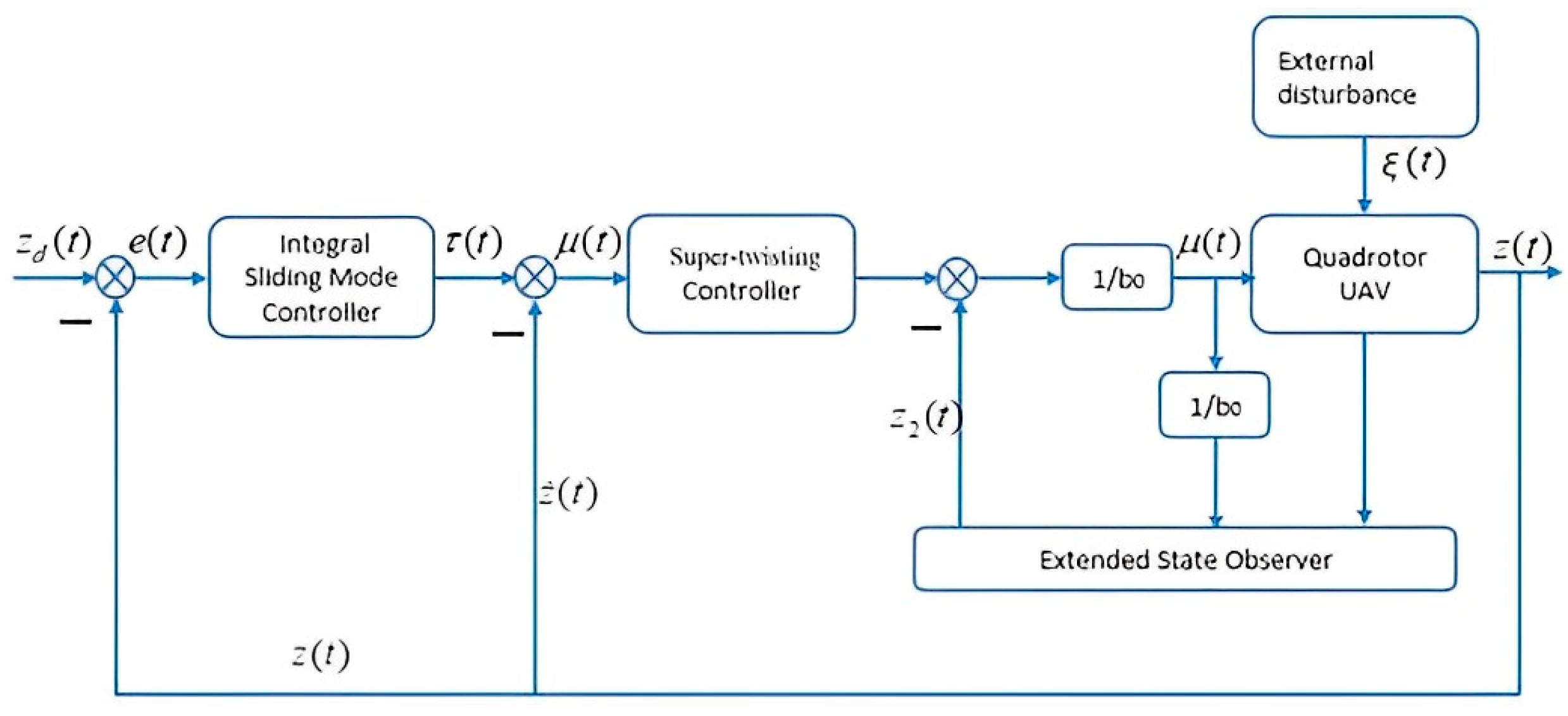
In this paper, the finite-time super-twisting controller (17) based on the finite-time ESO (4) is designed in the height velocity inner loop (2) to compensate for the external total disturbance and track a desired height velocity signal. In this section, an integral sliding mode controller is designed to drive a quadrotor UAV in the outer loop to improve the response speed of height control. Figure 2 shows the dual closed-loop height control strategy.
As shown in Figure 2 z d ( t )  is the expected height, and  e ( t )  is the error between the actual and expected heights; thus, we have
e ( t ) = z d ( t ) z ( t )
The integral sliding mode surface is
s p t = e t + k 1 0 t e t d t
where  k 1  is the adjustable positive parameter. Take its derivative and we have
s · p ( t ) = e · ( t ) + k 1 e ( t ) = z · d ( t ) τ ( t ) + k 1 e ( t )
where  τ ( t )  is the integral sliding mode controller, and it is also the expected value of the inner loop. In this section, the outer-loop controller is designed as
τ ( t ) = z · d ( t ) + k 1 e ( t ) + k 2 2 π arctan ( s p ( t ) k 3 )
where,  k 2  and  k 3  are the positive adjustable parameters. Considering the integral sliding mode surface and integral sliding mode controller, the Lyapunov function is
V 3 ( t ) = 1 2 s p 2 ( t )
Taking its derivative yields
V · 3 ( t ) = s p ( t ) s · p ( t ) = s p ( t ) ( z · d ( t ) τ ( t ) + k 1 e ( t ) ) = k 2 2 π s p ( t ) arctan ( s p ( t ) k 3 )
Due to the characteristics of  arctan ( ) , the equation  2 π s p ( t ) arctan ( s p ( t ) k 3 ) = γ | s p ( t ) |  holds, and  0 < γ < 1 . Moreover, there is
V · 3 ( t ) = k 2 γ | s p ( t ) |
Then we have that  V · 3 ( t ) < 0  holds. Therefore, the outer-loop error  e ( t )  eventually converges to zero, and the outer loop of the quadrotor UAV designed in this section is asymptotically stable.

5. Simulation and Experiment Results

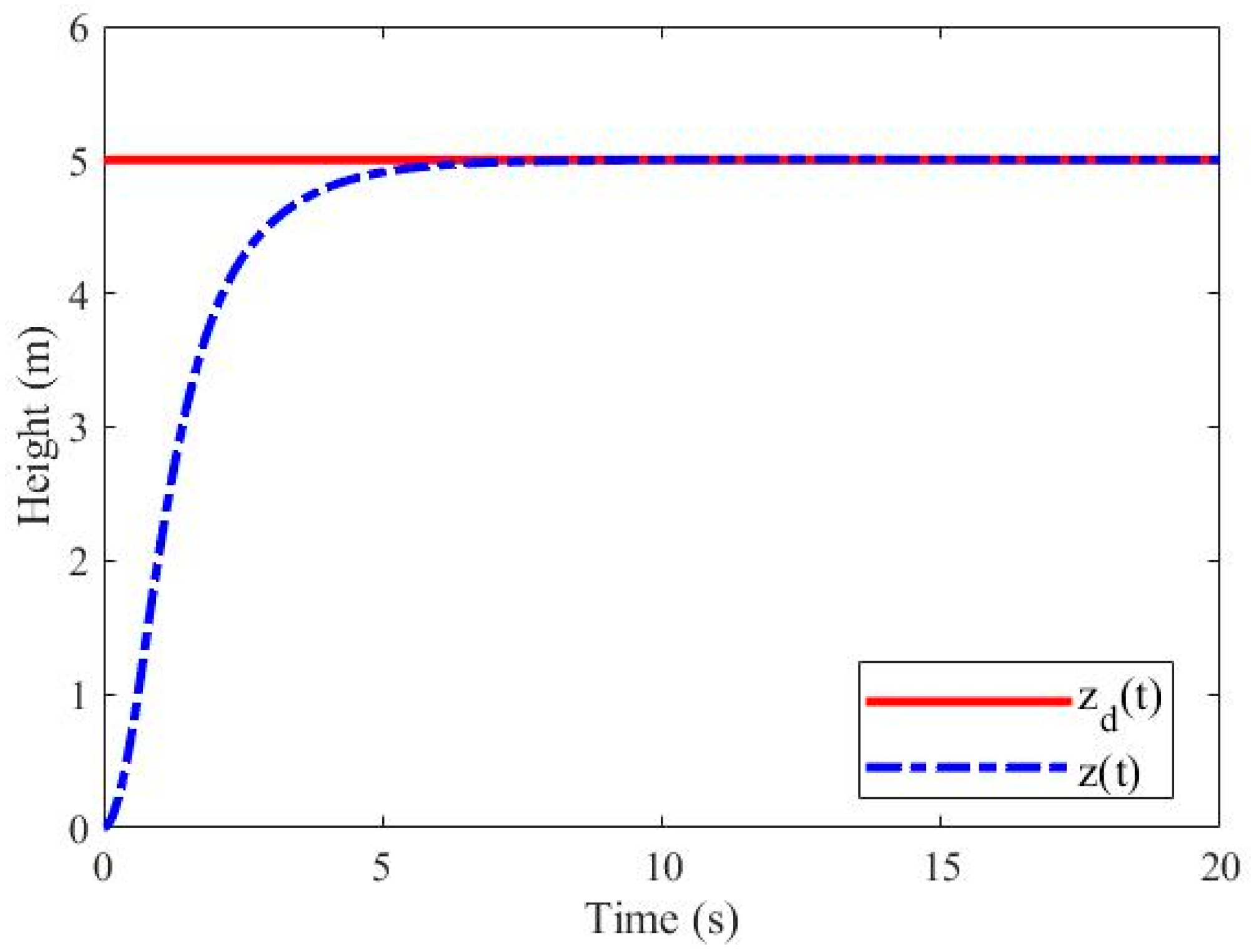
Due to the working characteristics of the quadrotor UAV, it usually includes two working modes of fixed height and lifting in actual flight tasks. Therefore, the simulation in this section consists of two parts, i.e., tracking a fixed signal  z d t = 5 m  and a periodic signal  z d t = 2 + 0.5 sin ( 0.01 t ) m , so as to verify the tracking effect of the simulation on different desired signals. In this simulation, the external disturbance  ξ t  is simulated as a periodic function given as  ξ t = 5 sin ( 0.01 t + cos ( 0.01 t ) ) . The control period of the system is 0.002 s and the initial value of each state is zero.
In this paper, the parameters include observer parameters  β 1 β 2 , and  β 3 , and controller parameters  α 1 α 2 k 1 k 2 , and  k 3 . For the observer parameters,  β i  with  i = 1 , 2 , 3  are required to be positive. In general, we first choose parameter  β 1  and then solve suitable  β 2  and  β 3  according to the conditions in Theorem 1. Our experience shows that a satisfactory estimation result is usually obtained by setting  β 1 = 30 β 2 = 5  and  β 3 = 800 . For the controller parameters, positive values  α 1 α 2 , k 1 k 2  and  k 3  represent the gains of the inner- and outer-loop controllers. They are selected based on the stability conditions in Theorems 2 and 3. Increasing these gains will speed up convergence but may result in a larger oscillation in the initial stage.
When tracking  z d ( t ) = 5 m , the parametric gains of the finite-time ESO are  β 1 = 30 , β 2 = 5 β 3 = 800  and  n = 0.5 . The parameters of the super-twisting controller are  α 1 = 100 α 2 = 2  and  b 0 = 1 . The parameters of the integral sliding mode controller are  k 1 = 8 k 2 = 0.01  and  k 3 = 0.5 . Figure 3 shows the simulation results of tracking fixed signals.
As can be seen from Figure 3, when tracking the fixed signal  z d t = 5 m , the actual height  z ( t )  converges to the expected height  z d ( t )  quickly and accurately. Figure 4 shows the tracking error for the fixed signal.
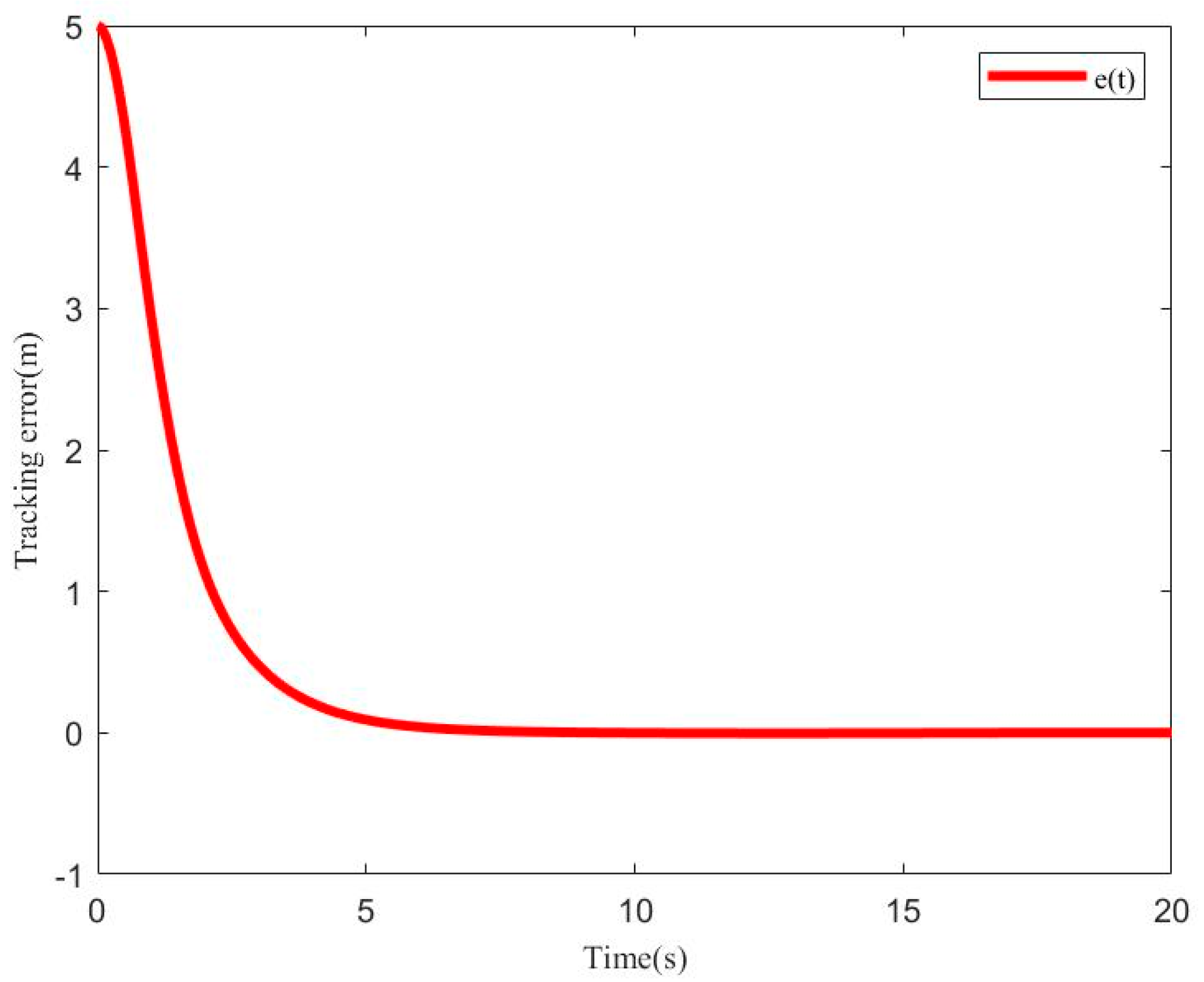
As can be seen from Figure 4, the tracking error  e t  quickly converges to zero and remains stable with the error not exceeding 0.003 m. Figure 5 shows the curve of the inner-loop control system when the fixed signal is tracked.
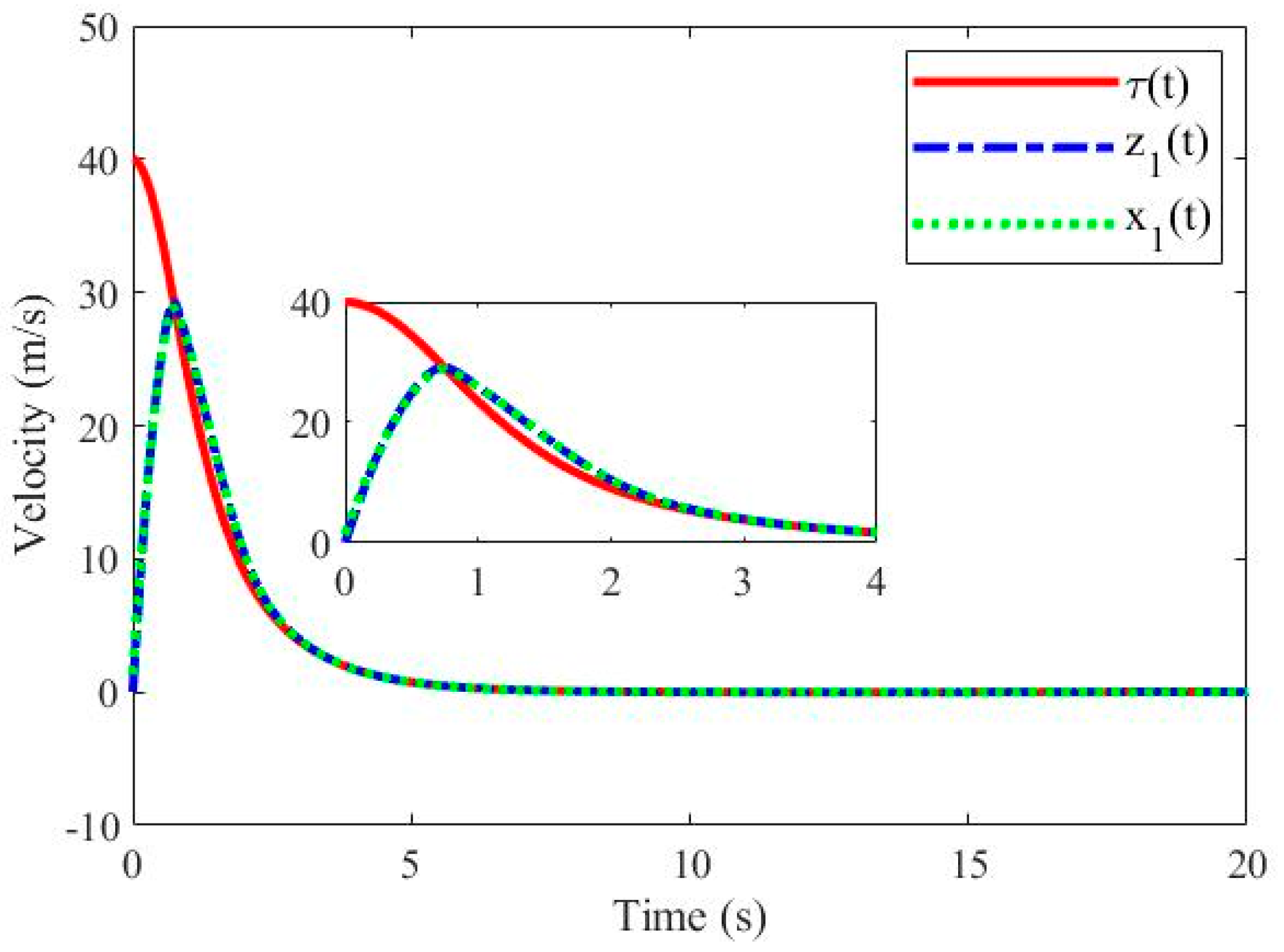
As can be seen from Figure 5 τ ( t )  is the expected value of the inner-loop control system. Under the control scheme designed for the inner loop,  x 1 ( t )  tracks  τ ( t )  stably, and the error converges to a small enough size within a finite time.  z 1 ( t )  is the estimation signal of the finite-time ESO designed in this paper. It can be seen that state  x 1 ( t )  can be estimated by  z 1 ( t )  accurately and in real time, which proves the effectiveness of the finite-time ESO. Figure 6 shows the disturbance observation curve of the finite-time ESO.
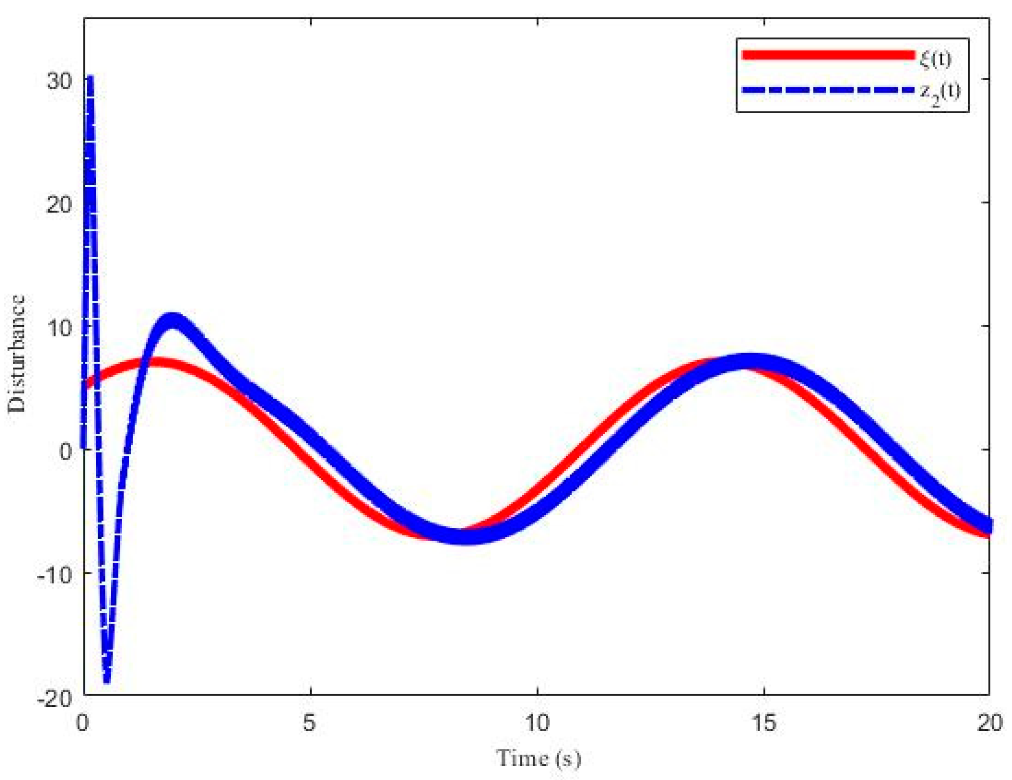
Figure 6 shows the tracking effect of the external disturbance  ξ t  by the finite-time ESO. It can be seen that after a period of convergence time, the estimated value  z 2 ( t )  is simulated for the external disturbance  ξ t , and the peak value is almost the same as the trend. Therefore, the inner-loop controller can effectively reduce the influence of external disturbance  ξ t  by compensating the estimated value of  z 2 ( t ) .
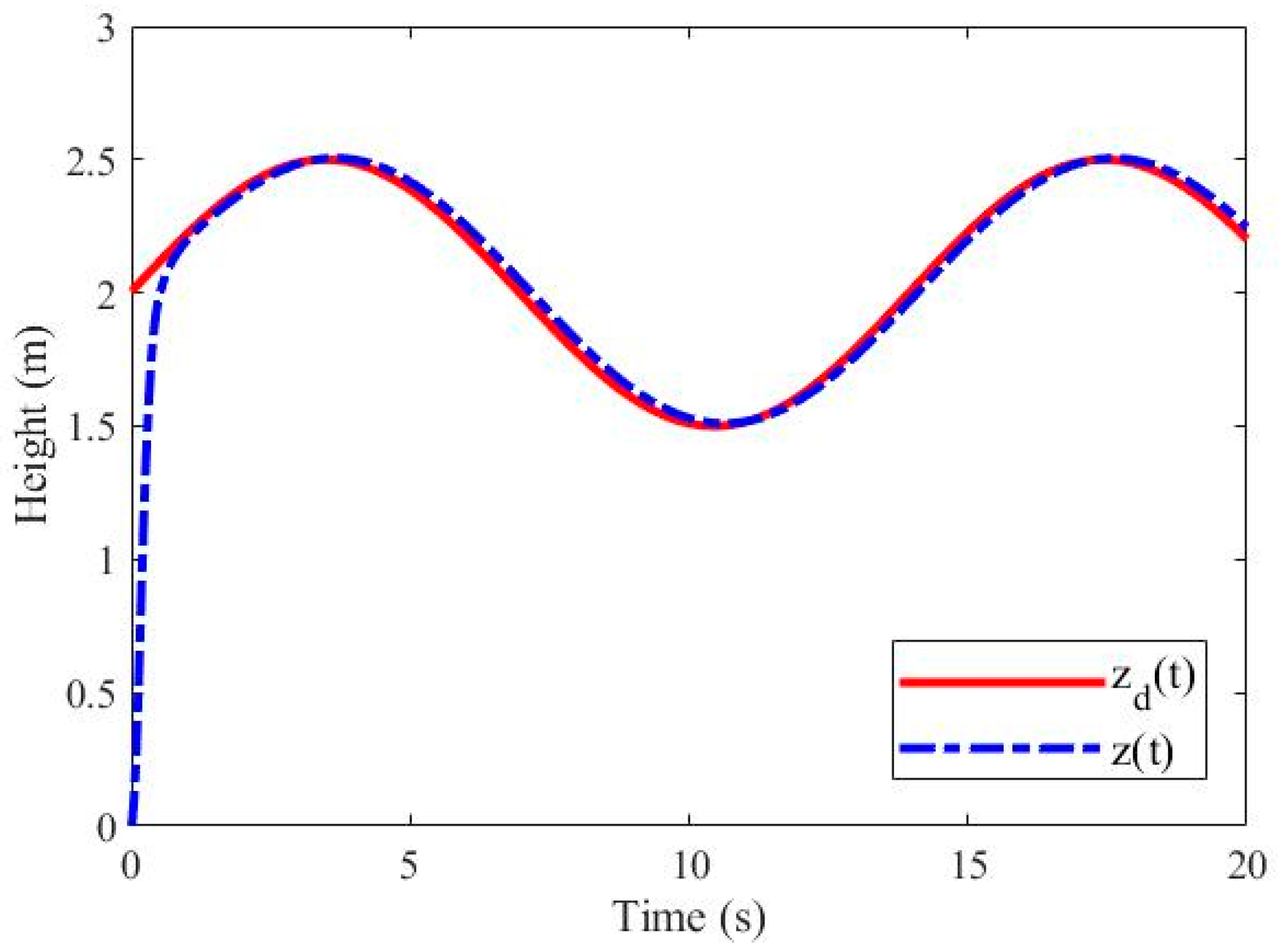
When tracking  z d t = 2 + 0.5 sin ( 0.01 t ) m , the parametric gains of the finite-time ESO used in simulation are  β 1 = 30 β 2 = 5 β 3 = 700  and  n = 0.5 . The parameters of the super-twisting controller are  α 1 = 600 α 2 = 2  and  b 0 = 1 . The parameters of the integral sliding mode controller are  k 1 = 55 k 2 = 0.5  and  k 3 = 0.5 . Figure 7 shows the simulation results of tracking the periodic signal.
As can be seen from Figure 7, when tracking the periodic signal  z d t = 2 + 0.5 sin ( 0.01 t ) m , the actual height  z ( t )  also converges to the expected height  z d ( t )  quickly and accurately. Figure 8 shows the tracking error for the period signal.
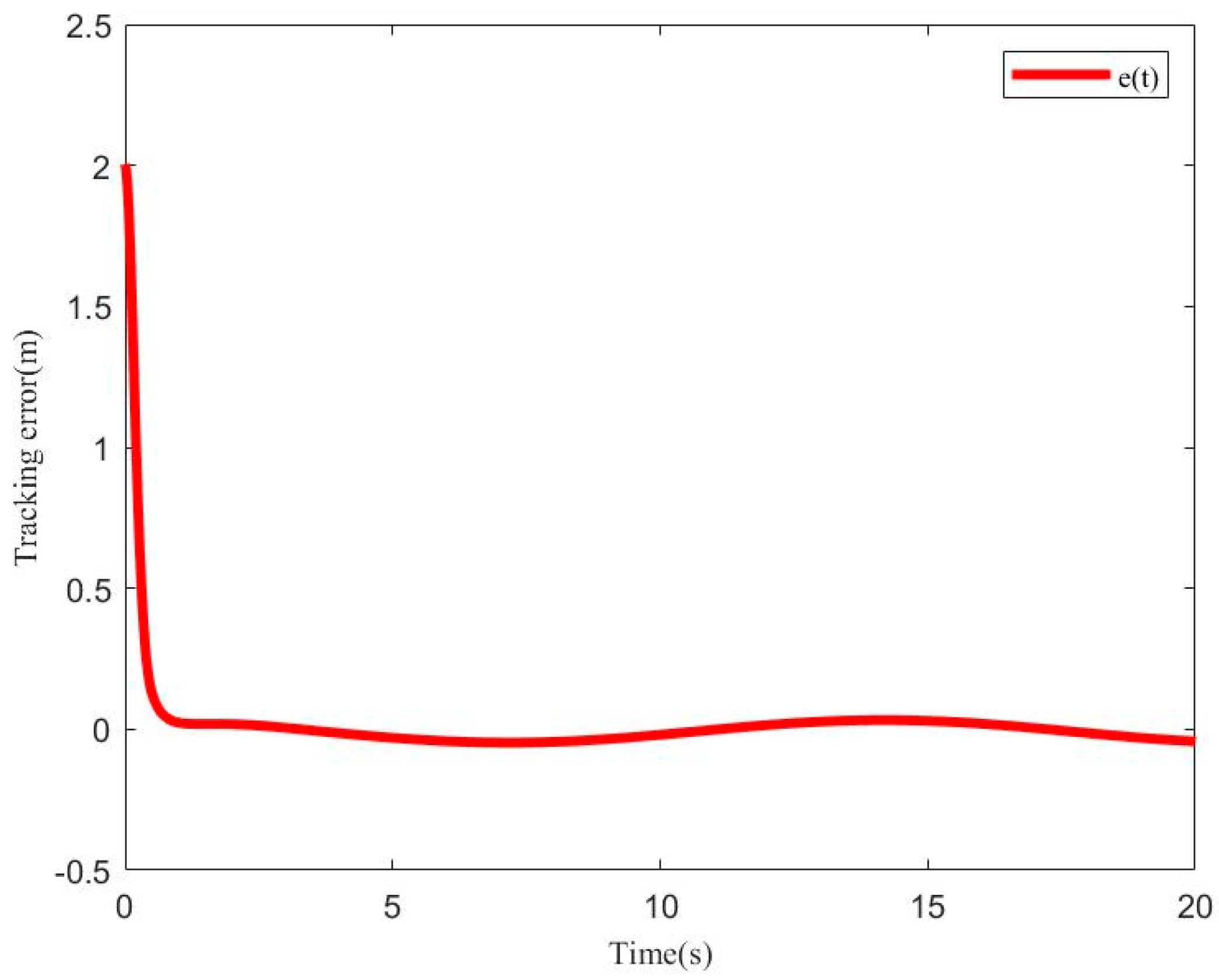
As can be seen from Figure 8, the tracking error  e t  quickly converges to a small neighborhood around zero and then remains within an error range of a neighborhood radius 0.034 m. Figure 9 shows the curve of the inner-loop control system for tracking the periodic signal.
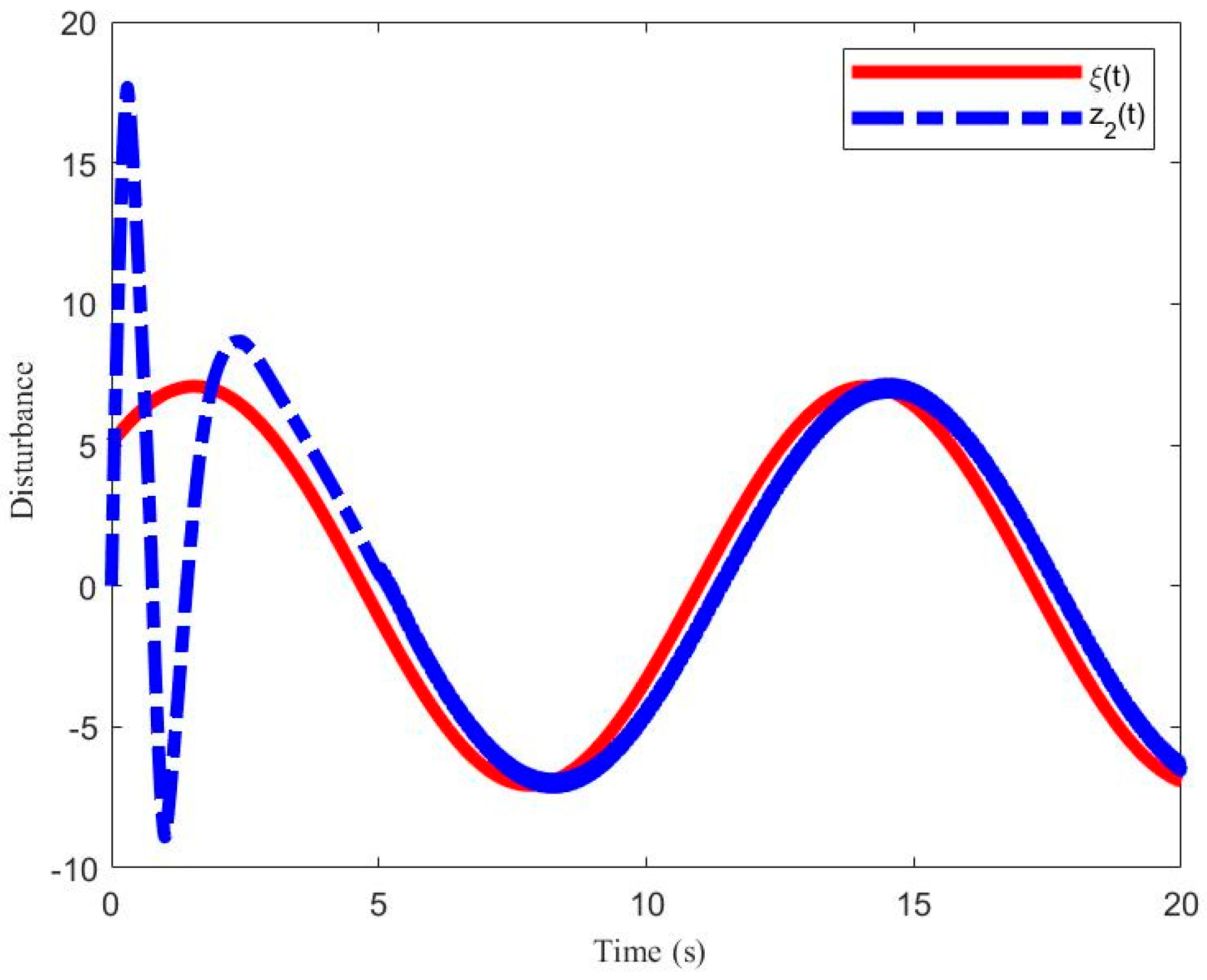
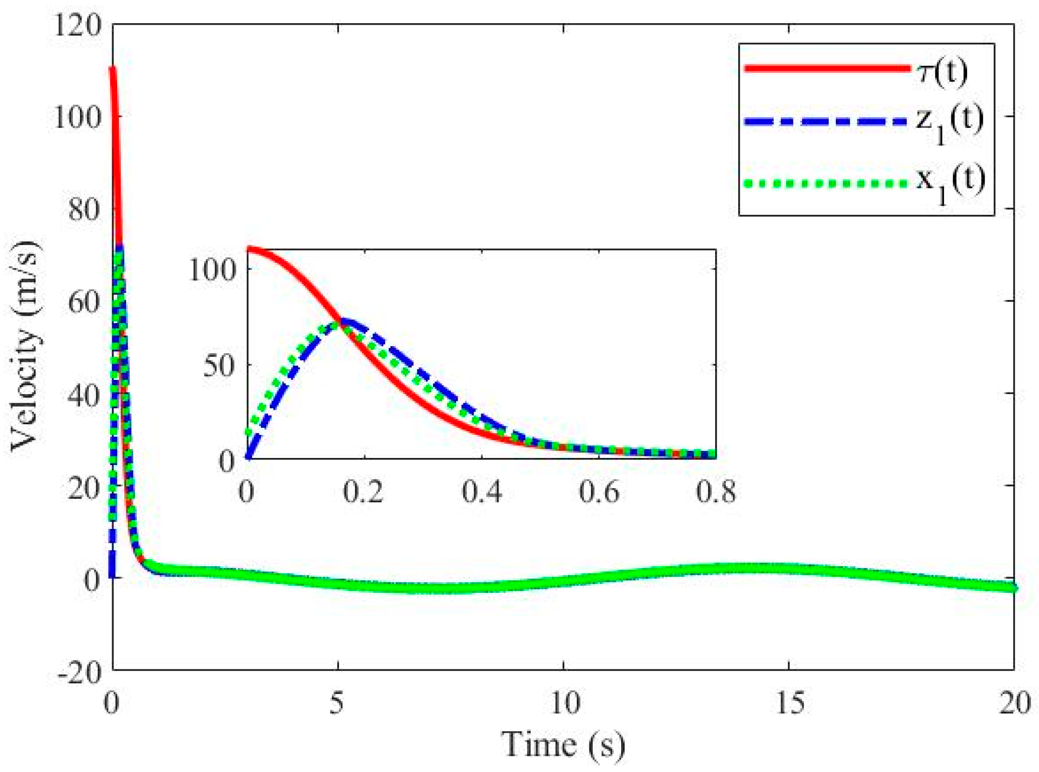
As can be seen from Figure 9, when tracking periodic signals,  τ ( t )  can also be tracked stably and quickly by  x 1 ( t ) , state  x 1 ( t )  can be estimated by  z 1 ( t )  in real time, and the error converges to small enough within a finite time. Figure 10 shows the disturbance observation curve of the finite-time ESO when tracking the periodic signal. Figure 10 shows the tracking of the external disturbance  ξ t  by the finite-time ESO. Also, after a period of convergence time, the estimated value  z 2 ( t )  is simulated for the external disturbance  ξ t , and the peak value is almost the same as the trend.
Therefore, through the above two simulations, it can be proved that the dual closed-loop control scheme designed in this paper is effective for the height control of the quadrotor UAV.
To highlight the advantages of the proposed control strategy in this paper, experiments are carried out by comparing both method one in [30] and method two in [31]. Note that there is also a super-twisting ESO and a super-twisting controller proposed in [30] for a quadrotor UAV. The main different between [30] and this paper is that there is a dual closed-loop control frame in this paper. Similarly, [31] introduces a dual closed-loop control frame, but there are active disturbance rejection controls and proportional-derivative controls in the inner and outer loops, respectively. The experiment results are shown with a quadrotor UAV in Figure 11.
In Figure 11, it is obtained that the proposed dual closed-loop control frame shows better effects on a characteristic of zero overshoot than method one in [30]. In addition, compared with method two from [31], it is obvious to see that the proposed control strategy in this paper achieves a more desired result. Also, existence of the proportional-derivative controller in the outer loop weakens stability performances of the quadrotor UAV. By replacing the proportional-derivative controller with an integral sliding mode controller, the experiment results show greater robustness, as shown in Figure 11.

6. Conclusions

In this paper, a dual closed-loop method has been designed for height control of a quadrotor UAV. The main results of the paper are threefold. First, a novel dynamics model has been developed including an inner loop and an outer loop to control the velocity and height, respectively. Second, a finite-time extended state observer has been obtained for the inner loop, which can speed up the convergence speed compared with the traditional extended state observer. Third, an integral sliding mode controller has been derived in the outer loop to reduce the chattering phenomenon of traditional SMCs and improve the control accuracy and convergence speed. The experiments have verified that the proposed dual closed-loop control method behaves better under a critically damped response in effects on zero overshoot and instantaneous following features. In future work, we will further explore lateral displacements while maintaining the desired height-tracking performance.

Author Contributions

Conceptualization, S.Z. and H.Y.; methodology, S.Z. and Y.X.; software, H.Y.; validation, L.M.; formal analysis, S.Z.; investigation, S.Z. and Y.X.; resources, S.Z.; data curation, L.M.; writing—original draft preparation, S.Z., L.M. and H.Y; writing—review and editing, S.Z., L.M. and H.Y.; visualization, L.M.; supervision, H.Y.; project administration, H.Y.; funding acquisition, H.Y. All authors have read and agreed to the published version of the manuscript.

Funding

This research received no external funding.

Institutional Review Board Statement

Not applicable.

Informed Consent Statement

Not applicable.

Data Availability Statement

Not applicable.

Conflicts of Interest

The authors declare no conflict of interest.

References

  1. Ma, W.; Li, H.; Wei, S. Research on hovering performance of quadrotor against combined wind field interference based on ADRC. Foreign Electron. Meas. Technol. 2020, 39, 71–76. [Google Scholar]
  2. Xie, S.; Chen, Q.; He, X. Predefined-time approximation-free attitude constraint control of rigid spacecraft. IEEE Trans. Aerosp. Electron. Syst. 2023, 59, 347–358. [Google Scholar] [CrossRef]
  3. Tao, M.; Chen, Q.; He, X. Fixed-time filtered adaptive parameter estimation and attitude control for quadrotor UAVs. IEEE Trans. Aerosp. Electron. Syst. 2022, 58, 4135–4146. [Google Scholar] [CrossRef]
  4. Rinaldi, M.; Primatesta, S.; Guglieri, G. A comparative study for control of quadrotor UAVs. Appl. Sci. 2023, 13, 3464. [Google Scholar] [CrossRef]
  5. Zhao, L.; Dai, L.; Xia, Y. Attitude control for quadrotors subjected to wind disturbances via active disturbance rejection control and integral sliding mode control. Mech. Syst. Signal Process. 2019, 129, 531–545. [Google Scholar] [CrossRef]
  6. Chen, K.; Ye, C.; Wu, C.; Wang, H.; Jin, L.; Zhu, F.; Hong, H. A novel open-closed-loop control strategy for quadrotor trajectory tracking on real-time control and acquisition platform. Appl. Sci. 2023, 13, 3251. [Google Scholar] [CrossRef]
  7. Zhang, X.; Xian, B.; Zhao, B.; Zhang, Y. Autonomous flight control of a nano quadrotor helicopter in a GPS-denied environment using on-board vision. IEEE Trans. Ind. Electron. 2015, 62, 6392–6403. [Google Scholar] [CrossRef]
  8. Zhou, Z.; Wang, H.; Wang, Y.; Xue, X.; Zhang, M. Distributed formation control for multiple quadrotor UAVs under Markovian switching topologies with partially unknown transition rates. J. Frankl. Inst. 2019, 356, 5706–5728. [Google Scholar] [CrossRef]
  9. Mystkowski, A. Implementation and investigation of a robust control algorithm for an unmanned micro-aerial vehicle. Robot. Auton. Syst. 2014, 62, 1187–1196. [Google Scholar] [CrossRef]
  10. Xiong, J.; Zheng, E. Position and attitude tracking control for a quadrotor UAV. ISA Trans. 2014, 53, 725–731. [Google Scholar] [CrossRef]
  11. Tan, L.; Liang, S.; Su, H.; Qin, Z.; Li, L.; Huo, J. Research on amphibious multi-rotor UAV out-of-water control based on ADRC. Appl. Sci. 2023, 13, 4900. [Google Scholar] [CrossRef]
  12. Han, J. From PID to active disturbance rejection control. IEEE Trans. Ind. Electron. 2009, 56, 900–906. [Google Scholar] [CrossRef]
  13. Li, P.; Yang, H.; Li, H.; Liang, S. Nonlinear ESO-based tracking control for warehouse mobile robots with detachable loads. Robot. Auton. Syst. 2022, 149, 103965. [Google Scholar] [CrossRef]
  14. Ho, C.; Ahn, K. Extended state observer-based adaptive neural networks backstepping control for pneumatic active suspension with prescribed performance constraint. Appl. Sci. 2023, 13, 1705. [Google Scholar] [CrossRef]
  15. Yang, H.; Sun, J.; Xia, Y.; Zhao, L. Position control for magnetic rod-less cylinders with strong static friction. IEEE Trans. Ind. Electron. 2018, 65, 5806–5815. [Google Scholar] [CrossRef]
  16. Liu, Y.; Li, H.; Lu, R.; Zuo, Z.; Li, X. An overview of finite/fixed-time control and its application in engineering systems. IEEE/CAA J. Autom. Sin. 2022, 9, 2106–2120. [Google Scholar] [CrossRef]
  17. Yang, W.; Shi, Z.; Zhong, Y. Robust backstepping non-smooth practical tracking for nonlinear systems with mismatched uncertainties. Int. J. Robust Nonlinear Control 2022, 32, 3674–3695. [Google Scholar] [CrossRef]
  18. Alonge, F.; D’Ippolito, F.; Fagiolini, A.; Garraffa, G.; Sferlazza, A. Trajectory robust control of autonomous quadcopters based on model decoupling and disturbance estimation. Int. J. Adv. Robot. Syst. 2021, 18, 1–12. [Google Scholar] [CrossRef]
  19. Yu, X.; Yang, J.; Li, S. Finite-time path following control for small-scale fixed-wing UAVs under wind disturbances. J. Frankl. Inst. 2020, 357, 7879–7903. [Google Scholar] [CrossRef]
  20. Du, H.; Zhu, W.; Wen, G. Distributed formation control of multiple quadrotor aircraft based on non-smooth consensus algorithms. IEEE Trans. Cybern. 2019, 49, 342–353. [Google Scholar] [CrossRef]
  21. Wang, Y.; Hu, J. Robust control for a quadrotor aircraft with small overshoot and high-precision position tracking performance. J. Frankl. Inst. 2020, 357, 13386–13409. [Google Scholar] [CrossRef]
  22. Bhat, S.; Dennis, S. Finite-time stability of continuous autonomous systems. SIAM J. Control Optim. 2000, 38, 751–766. [Google Scholar] [CrossRef]
  23. Hou, Z.; Isabelle, F. Interactive leader-follower consensus of multiple quadrotors based on composite nonlinear feedback control. IEEE Trans. Control Syst. Technol. 2018, 26, 1732–1743. [Google Scholar] [CrossRef] [Green Version]
  24. Abdul Ghaffar, A.F.; Richardson, T.; Greatwood, C. A combined model reference adaptive control law for multirotor UAVs. IET Control Theory Appl. 2021, 15, 1474–1487. [Google Scholar] [CrossRef]
  25. Zhao, J.; Ding, X.; Jiang, B.; Jiang, G.; Xie, F. A novel control strategy for quadrotors with variable mass and external disturbance. Int. J. Robust Nonlinear Control 2021, 31, 8605–8631. [Google Scholar] [CrossRef]
  26. Vahdanipour, M.; Khodabandeh, M. Adaptive fractional order sliding mode control for a quadrotor with a varying load. Aerosp. Sci. Technol. 2019, 86, 737–747. [Google Scholar] [CrossRef]
  27. Zheng, L.; Zhang, Z. Convergence and robustness analysis of novel adaptive multilayer neural dynamics-based controllers of multirotor UAVs. IEEE Trans. Cybern. 2021, 51, 3710–3723. [Google Scholar] [CrossRef] [PubMed]
  28. Outeiro, P.; Cardeira, C.; Oliveira, P. Multiple-model adaptive control architecture for a quadrotor with constant unknown mass and inertia. Aerosp. Sci. Technol. 2021, 117, 106899. [Google Scholar] [CrossRef]
  29. Avram, R.C.; Zhang, X.; Muse, J. Nonlinear adaptive fault-tolerant quadrotor altitude and attitude tracking with multiple actuator faults. IEEE Trans. Control Syst. Technol. 2017, 26, 701–707. [Google Scholar] [CrossRef]
  30. Cui, L.; Zhang, R.; Yang, H.; Zuo, Z. Adaptive super-twisting trajectory tracking control for an unmanned aerial vehicle under gust winds. Aerosp. Sci. Technol. 2021, 115, 106833. [Google Scholar] [CrossRef]
  31. Yang, H.; Cheng, L.; Xia, Y.; Yuan, Y. Active disturbance rejection attitude control for a dual closed-loop quadrotor under gust wind. IEEE Trans. Control Syst. Technol. 2018, 26, 1400–1405. [Google Scholar] [CrossRef]
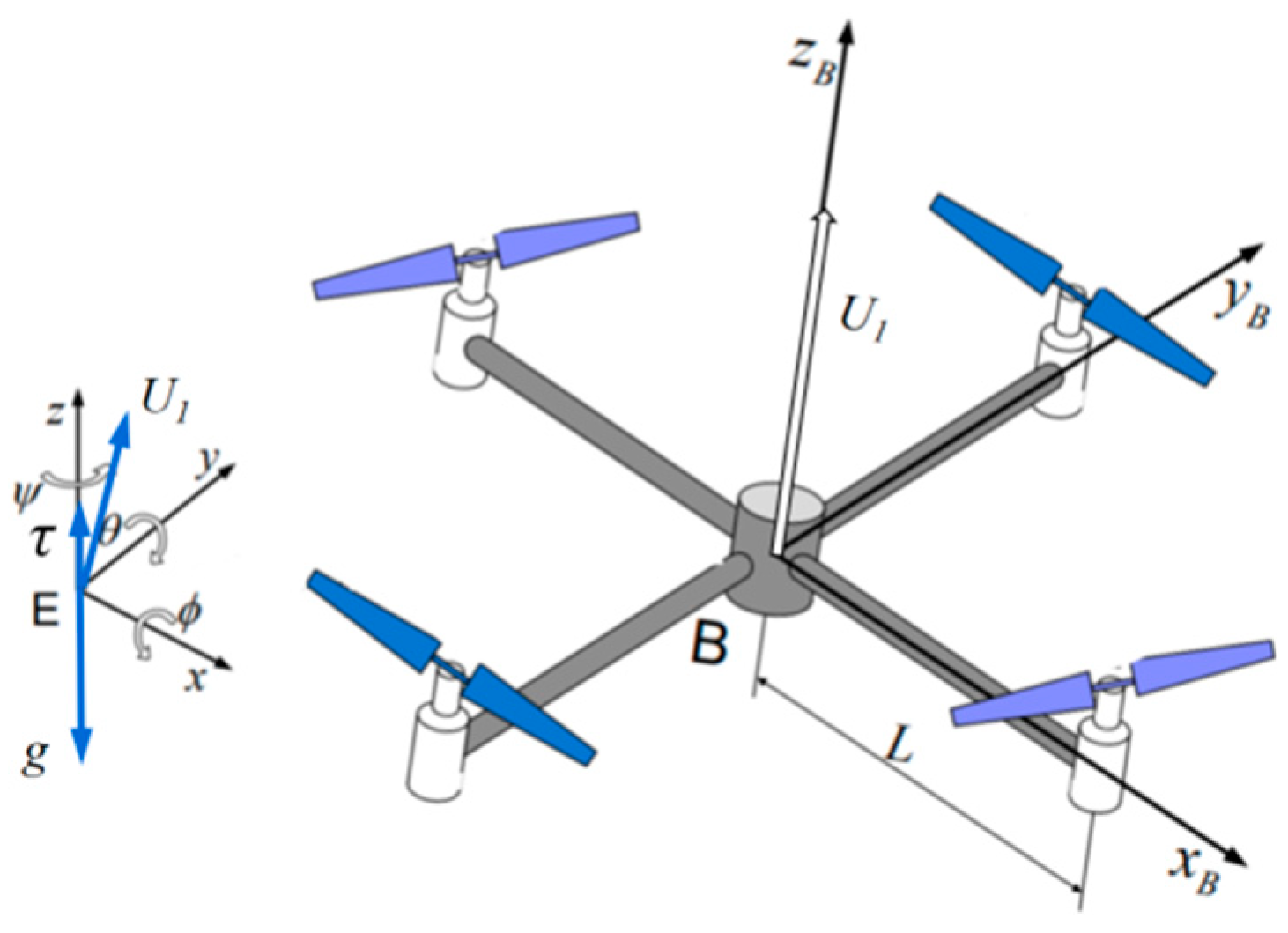
Figure 1. Schema of a quadrotor aircraft.
Applsci 13 07914 g001
Figure 2. Dual closed-loop height control strategy structure diagram.
Applsci 13 07914 g002
Figure 3. Simulation result of tracking the fixed signal.
Applsci 13 07914 g003
Figure 4. Tracking error for the fixed signal.
Applsci 13 07914 g004
Figure 5. Tracking curves for the fixed signal in the inner loop.
Applsci 13 07914 g005
Figure 6. Disturbance observation curve for the fixed signal by the finite-time ESO.
Applsci 13 07914 g006
Figure 7. Simulation result of tracking the period signal.
Applsci 13 07914 g007
Figure 8. Tracking error for the period signal.
Applsci 13 07914 g008
Figure 9. Tracking curves for the periodic signal in the inner loop.
Applsci 13 07914 g009
Figure 10. Disturbance observation curve for the periodic signal by the finite-time ESO.
Applsci 13 07914 g010
Figure 11. Performance comparison of the height control methods.
Applsci 13 07914 g011
Disclaimer/Publisher’s Note: The statements, opinions and data contained in all publications are solely those of the individual author(s) and contributor(s) and not of MDPI and/or the editor(s). MDPI and/or the editor(s) disclaim responsibility for any injury to people or property resulting from any ideas, methods, instructions or products referred to in the content.