1. Introduction
The design of seismic-resilient buildings has been increasingly advanced in the last years with the aim of promoting the use of innovative sustainable systems and methods for the mitigation of seismic consequences on the structural performance of framed structures. Low-damage and free-from-damage design strategies mainly aim at protecting the primary load-bearing systems of the structure under ultimate-level seismic loads. Therefore, the main structural frames are equipped with damping devices located in accessible and easy-to-inspect locations where the damage concentrates, while the primary structure remains mostly undamaged or easily repairable after a severe seismic event.
Several solutions available in the literature are based on friction devices, which can mainly work as sliding-hinge joints [
1,
2,
3] or removable friction dampers [
4,
5]. These systems are expected to dissipate the seismic energy through friction forces that develop between sliding plates connected by preloaded bolts, e.g., [
1,
6]. The most investigated configurations of friction devices are studied as applications to steel-framed structures, e.g., [
2,
3,
5,
7,
8]. Conversely, only a few studies have been conducted on RC structures up to now, e.g., [
9,
10,
11,
12,
13,
14]. Actually, it has to be noted that RC frames are not easily equipped with efficient and cost-effective damage-proof connections, especially in the case of cast-in situ structures. Moreover, the introduction of these devices implies the modification of the manufacturing process, leading to a significant increase in the total cost of the construction.
Recently, the authors proposed a friction damper for beam-to-column connections (BCCs) applied to RC moment-resisting frames (MRFs) endowed with semi-prefabricated hybrid steel-trussed concrete beams (HSTCBs), and standard RC pillars [
15,
16,
17]. HSTCBs are a class of hybrid beams constructed with a prefabricated steel truss embedded within a concrete core cast-in-place, which have been extensively studied in the literature, using both experimental, numerical, and analytical methods, e.g., [
18,
19,
20]. The proposed solution is a passive vibration-control system not already available in the market that consists of a damping device located at both beam-to-column and column-base joints, and it follows the low-damage design approach.
In this regard, it can be noteworthy to mention that three general types of control systems are available in the field of vibration control of structures, namely, passive-, semi-active-, and active-control systems. Passive control is designed as a tool for enhancing the damping capacity, stiffness, or even the strength of the structure by introducing specific devices able to develop control forces which oppose the seismic motion of the structure. Conversely, active and semi-active systems adopt controllable forces to dissipate energy by means of specific devices endowed with sensors and real-time monitoring. These systems are widely adopted, especially in base-isolated multi-storey buildings, with the aim of reducing the seismic base-level displacements while keeping the superstructure at high-performance level (among others, Refs. [
21,
22]). Considering the different functioning of these systems, passive control has the advantages of lower costs and higher reliability, and, therefore, it is considered in this feasibility study.
In this paper, three design solutions are described for the BCCs: connection type A, i.e., a friction-damping device with crossed slotted holes; connection type B, i.e., a friction-damping device with curved slotted holes; and connection type C, i.e., a friction-damping device with curved slotted holes and added Perfobond connectors. Their mechanical performances are compared by means of 3D finite element (FE) modelling, performing cyclic analyses. However, a relevant issue is also the development of devices aimed at re-centering the structure, i.e., achieving negligible residual displacements at the end of the earthquake motion. Therefore, two proposals of self-centering systems at the column-base connections (CBCs) are also explored; the first is obtained with preloaded threaded bars and disk springs, and the second with friction pads and preloaded bolts. In this case, a simple two-storey and two-span MRF is analyzed by means of pushover analyses and non-linear time history analyses. The main results show that, for BCCs, solution C is the most performing because it generally helps to not develop high damage levels in the main structure (beams, columns, and joints). Moreover, it achieves a good amount of dissipated energy as can be noticed from the shape of the hysteretic cycles, which are wide and stable. On the other hand, for CBCs, the results showed that the self-centering systems are essential for limiting residual drifts, and for preventing the plasticization phenomenon at the base of the columns.
In the following sections, firstly, the three BCCs and the two CBCs will be presented, then, several MRFs will be analyzed, and the comparison between traditional and innovative solutions will be conducted through push-over analyses and non-linear time history analyses (NLTHAs).
2. Beam-to-Column Connections
Before describing the proposed solutions, the principles of the calculation are briefly summarized. First of all, the design-bending moment Md has to be known. In this case, the feasibility study is conducted assuming Md = 110 kNm. If we assume an overstrength factor of 1.5, then the positive moment strength of the beam that belongs to the sub-assemblage results in MRd = 165 kNm.
For every
i-th solution, the design sliding force is calculated for the corresponding internal lever arm
zi:
According to Eurocode 3 [
23], the slip resistance of the connection,
Fs,Rd,i, can be calculated as:
where
Ares,i,
nbi, and
fub,i are the transversal area and number of bolts, and their ultimate strength, respectively, while
ns and
μ are the first, the number of planes where friction develops and the second, the slip factor. It is noteworthy to remark that this feasibility study is conducted by adopting metal-to-metal contact as first approach. However, it is known that the international code ASCE07-22 [
24] does not allow this type of contact in friction dampers; conversely, the introduction of friction pads is prescribed. In this regard, the authors are currently developing further insights for analyzing best-performing friction materials. Some preliminary results can be found in Pagnotta et al. [
25].
This study assumes ns = 2 and μ = 0.4. Moreover, it has to be noted that Equation (3) is the function of the preloading force of each bolt, Fpc,i = 0.7·fub,i·Ares,i.
With the aim of limiting the preloading force in the range 30–60% of the code-compliant value, a coefficient t
s,i can be introduced for setting the stress level of each preloaded bolt [
26]. If
ts,i is assumed as the ratio between the sliding force reported in Equation (1) and the code-compliant slip resistance of Equation (2), then the effective preload design value is:
Based on these calculation criteria, the following sections present three different structural solutions for BCCs characterized by different mechanical performances in terms of stability of the cyclic behavior and efficacy of their dissipation capacity. They are named BCC-1, BCC-2, and BCC-3, respectively.
Table 1 reports the values of the design sliding force, the stress-level coefficient, and the effective preload for the proposed solutions.
2.1. BCC-1: Device with Crossed-Slotted Holes
The first solution analyzed consists of a friction device with a pin on the top of the connection to the column and an assembly of steel plates with crossed holes with slotted shape on the lower part of the connection. This device is here indicated as BCC-1 and the details of all constituent parts are reported in
Figure 1a. In the case of BCC-1, six preloaded bolts are used, type M16, class 10.9; the internal lever arm z
1 is equal to 399 mm, while the angle α
1 between the sliding-force application point and the axis of the beam measures 61°.
The system is modelled through the finite element (FE) method. The FE software used for the simulation is Abaqus/CAE [
27]. A cross-section of 250 × 300 mm
2 for the beam and 300 × 400 mm
2 for the column are assumed. In the joint model, the structural elements’ length is 2500 mm for the beam and 3000 mm for the column. The latter is pinned at the ends, while a concentrated vertical force applies a cyclic displacement to the tip of the beam. The FE type used for the concrete parts is the first-order hexahedron named C3D8R, while the steel elements which constitute the connection are modeled with linear tetrahedra, type C3D4. This FE model is conducted under the simplified hypotheses of elastic behavior of all components and by neglecting the steel reinforcement of beam and column, thus, focusing only on the mechanism of the friction device. To this scope, the ideal fixed encastre is modelled for connecting the damping device to both beam and column while realistic constraints and interaction properties are simulated for the mechanism of the main top pin and for the sliding plates. A multi-point constraint of type “beam” is assumed between the longitudinal pin axes and the internal surfaces of the holes, while a friction mechanism is introduced in the sliding plates, with a friction coefficient of 0.4. Rigid normal contacts are also modeled between the bolt shanks and the internal surfaces of both circular and slotted holes.
A cyclic test is performed with displacements of ±100 mm, whose results are reported in
Figure 1b as a normalized moment-rotation curve. It can be noted that the clearance around the pin connection causes resistance between the friction plates when the pin moves before contact with the edges of the hole. This is an undesirable contribution, which negatively affects the system’s stiffness and dissipation capacity. Finally, from
Figure 1c, which shows the stress state at peak, it can be observed that stresses are under the elastic limit in the whole model with the exception of a limited stress concentration in the sliding plate, due to the localized contact against the bolt shank.
2.2. BCC-2: Curved-Slotted Hole System
The second device analyzed is endowed with curved slotted holes and achieves the upper connection to the column by means of a T-stub, which is expected to develop a plastic hinge in correspondence to its weakest cross-section characterized by two 20 mm diameter holes (
Figure 2a). This solution has five M18 preloaded bolts of class 10.9; the internal lever arm is
z2 = 380 mm, and the angle α
2 = 68°. The FE types used in this model are first-order tetrahedra (C3D4) for the steel elements of the connection, with the exception of the C-profile used for connecting the upper T-stub to the column. This C-profile is modeled with linear hexahedra (C3D8R), as well as the concrete column. Moreover, two-node linear beam elements are used for modelling the HSTCB reinforcement (longitudinal and diagonal rebars, and vertical and inclined stirrups). The FE model developed is more detailed because it takes into account the nonlinear behavior of the materials [
17]. The main mechanical parameters of concrete are: f
c = 25 MPa (compressive strength), E
0 = 28,960 MPa (elastic modulus), f
t = 2.56 MPa (tensile strength), and G
F = 0.13 N/mm (fracture energy). The modelled steel is class B450C for rebars embedded in concrete and S355 for plates, with elastic modulus E
s = 210,000 MPa. The constitutive model of steel considers an elastic perfectly plastic behavior. Moreover, the FE model considers a perfect bond between the concrete core and the steel truss and reinforcement of the beam. The other main contact properties are assumed as follows: frictionless sliding between the bottom plate of the beam and the concrete core; frictional behaviour between the sliding steel plates, with a friction coefficient equal to 0.4; and ideal rigid contacts in all normal local directions. The results of a cyclic analysis with imposed displacement of ±100 mm are reported in
Figure 2b; it can be noted that this device does not present the negative sliding effect previously due to the clearance in the top hinge; here, the center of rotation develops near the weakest cross-section of the T-stub (
Figure 1c), allowing a major dissipation capacity, even though a slight shifting of the rotation center is noticed during the analysis. The responses for the positive and negative bending moments are almost symmetric, and limited damage is experienced during the loading–unloading cycles.
2.3. BCC-3: Curved-Slotted Hole Device Combined with Perfobond Connectors
The third system differs from BCC-2 in these two main features: the central friction plate is extended throughout the concrete core of the beam, by developing a so-called Perfobond connector; the T-stub on the top is bolted to a horizontal plate welded to the Perfobond connector, while the top reinforcement of the beam is welded to the same plate. This solution results in a stiffer connection where M20 bolts of class 10.9 are adopted for making the sliding system (
Figure 3a). In BCC-3, the internal lever arm is
z3 = 374 mm and α
3 = 68°. In this model, the HSTCB is modeled with linear tetrahedra (C3D4) while all other FE types are solid linear bricks (C3D8R) and two-node beams are used for the steel reinforcement of the column. Cohesive interaction is used for modeling steel-to-concrete bond in the beam according to the analytical model proposed by Eligehausen et al. [
28], while a perfect bond is assumed in the RC column. Frictional behavior is set for the damping device components, adopting the same parameters used in BCC-2 model.
The FE model developed presents a slightly different setup scheme because the bottom end of the column is loaded with a lateral force which applies a cyclic displacement parallel to the beam axis; moreover, the column is preloaded with an axial force. Moreover, the compressive strength of concrete is f
c = 30.31 MPa and the Young’s modulus E
c = 30,683 Mpa. The steel elements are modelled adopting a multi-linear behaviour with hardening phases and material rupture [
29,
30]. Three cyclic analyses are performed for 0.5
Md,
Md, and
Mrd = 1.5
Md, defining cycles with amplitude ±Θ
y, ±4Θ
y, and ±Θ
max = ±7Θ
y, the yielding chord rotation being Θ
y = 7 mrad. This loading scheme is chosen according to the code ACI 374.2R-13 [
31] with the aim of achieving multiples of the yielding chord rotation. However, only the three aforementioned amplitudes have been adopted in order to contain the computational time demand of the analysis. The results are reported in
Figure 3b. It can be observed that the stiffer top connection is able to prevent the shifting of the rotation center, allowing more stable hysteresis cycles. The cycles are wide and proportional to the different values of preload in the bolts.
Figure 3c reports the strain state at the maximum rotation, for the cycles developed at
Md value. The figure shows that the steel elements of the friction damper are elastic, with localized plastic strain concentrations at the end of the intersection between the bottom plate of the truss and the sliding holed plate. The upper T-stub assumes higher inelastic strain values in the section devoted to develop the rotation center of the system.
3. Column-Base Connections
The friction devices at BBCs need to be coupled with self-centering systems designed at the column base. Two solutions are proposed (
Figure 4), aiming at containing the structure’s residual drift within an allowable maximum value, i.e., 0.5%.
The first column-base device (CBC-1) is a system with preloaded threaded bars used in combination with disk springs. It is made by a column splice with bearing plates at its web and flanges. Slotted holes in the column allow the rotation of the CBC. The connection is characterized by a bilinear elastic moment-rotation behavior, provided by the combination of threaded bars and disk springs. Therefore, the use of plastic hinges at the column base is avoided. It has to be noted that if all elements behave elastically, the connection does not exhibit any dissipative capacity and it will not be able to ensure an adequate maximum inter-storey drift and residual displacements. Therefore, the other connection is investigated (CBC-2), introducing friction pads and preloaded bolts aimed at providing the required dissipation capacity. The solution reported in this paper represents the solution originally proposed by Latour et al. [
32] and here adapted to an RC column connection.
In the following section, the global response of the connection is analysed in terms of moment-rotation behavior by performing the seismic analysis of a two-storey MRF.
4. Seismic Analysis of a Two-Storey MRF
Simple MRFs are modelled by SeismoStruct software [
33] for analyzing the effects of different friction dampers in BCCs. The RC frame has two storeys and two spans of 3 m height and 5 m length, respectively. The columns have a cross-section of 300 × 400 mm
2 and it is reinforced with 10 20 mm diameter rebars. The HSTCBs have an upper chord comprised of three rebars with diameter of 16 mm, a lower chord made with a 5 mm thick steel plate and diagonal rebars of 12 mm of diameter and 300 mm spacing. The HSTCBs are slab-thick beams with cross-section of 300 × 250 mm
2. First of all, a traditional frame (TF) is modeled as a benchmark; then, the innovative frame (IF) is modelled by introducing BCC-2 at joints. Conversely, the behavior of the frame endowed with BCC-3 is still under investigation by the authors. Furthermore, the performance of the IF is also investigated in the presence of CBC-1; this frame is indicated as an innovative frame with threaded bars and disk springs (IF-TB). Finally, the effects of CBC-2 are analysed, and the frame is indicated as an innovative frame endowed with threaded bars and disk springs with friction devices (IF-FD). Non-linear time history analyses (NLTHAs) are performed adopting 30 artificial accelerograms [
34] whose duration is 30 s, whit a strong motion phase of 20 s. The generated accelerograms are response-spectrum-compatible and they are obtained through the process proposed initially by Vanmarcke and Gasparini [
35] and successively modified by Cacciola et al. [
36], who adopted the modulating function by Jennings et al. [
37]. As an example,
Figure 5 reports one of the generated artificial accelerograms adopted for the analysis. At the end of the seismic action, five more seconds of free oscillation is added to the analysis for assessing the residual drift. Moreover, the intensity of the adopted spectrum-compatible accelerograms was amplified with a scale factor of 1.7 in order to produce an extensive cracking of the panel zones and the loss of bond of the steel reinforcement, other than the development of plastic hinges. The behavior factor adopted is q = 3. The vertical loads applied to the frame consist of 14.5 kN/m
2 of dead and live loads while 38 kN/m are added for considering the seismic masses due to the transversal frames of a spatial structure.
4.1. Model of the Traditional RC Frame Panel Zone
In the analysis of the TF, the panel zone is modeled through a system of rotational springs and rigid links at the intersection between the beams and the column (
Figure 6), while the latter are modeled using distributed plasticity fiber-section elements with a force-based formulation. More in detail, the shear panel zone is modeled by means of link elements, which have uncoupled axial, shear, and flexural behavior, endowed with force-displacement or moment-rotation relationship. Moreover, a rotational spring is placed at the center of the beam-to-column joint for modelling the relative rotation between HSTCB and pillar caused by the shear distortion of the joint. For this rotational spring, a “multi-line” model is adopted, which is based on the polygonal hysteretic model by Sivaselvan and Reinhorn [
38]. The analysis parameters are collected in
Table 2 on the basis of those provided in Sivaselvan and Reinhorn [
39]. The table reports the parameters that define the backbone curve and the hysteresis shape.
Rigid links are also used to connect the central node of the panel zone with the interface elements put between beam and joint and column and joint, demanding the whole cyclic response of the panel to the central rotational spring. The interfaces between the beam or column and the joint are modeled with rotational springs able to reproduce the effects of bond loss between longitudinal steel reinforcement and concrete core. These springs follow the “gen-hyst” model and the parameters adopted for the definition of backbone curve and hysteretic cycle shape are reported in
Table 2. Finally, the constitutive law adopted for concrete is that proposed by Mander et al. [
40] modified by Martinez-Rueda and Elnashai [
41].
4.2. Implementation of Friction BCCs
When analysing the IF endowed with HSTCBs connected to the RC columns by means of BCC-2, a modification of the panel zone modelling is required, as shown in
Figure 7. Again, a non-linear rotational spring is placed in the panel zone at the intersection between beam and column axis, for simulating the joint shear deformation. The analysis parameters are reported in
Table 3. Rotational springs again are used for modelling the bar-slip phenomenon and the parameters adopted are the same used for the traditional frame, previously reported in
Table 2. The friction device is modeled using bilinear kinetic rotational springs, endowed with a rigid elastic branch and very low stiffness in the post-yielding branch. More in detail, the parameters adopted for modelling the bilinear kinetic rotational spring are: initial rotational stiffness k
i = 10
6 kNm/rad; yielding moment M
y = 110 kNm; and post-yield stiffness ratio compared to the elastic stiffness r = 10
−4.
4.3. Modeling of the Re-Centering Systems
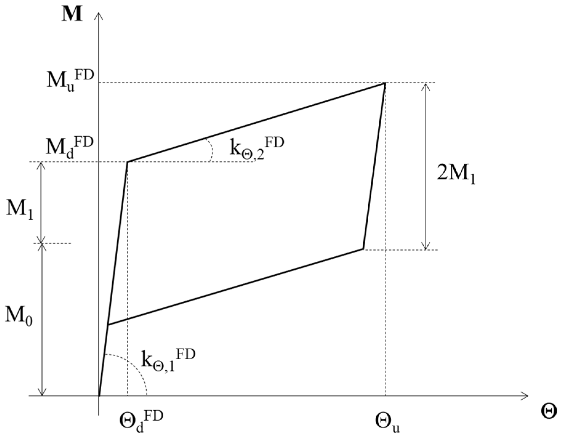
The self-centering base connections are simulated by means of non-linear rotational springs, whose theoretical moment vs. rotation diagram is shown in
Figure 8. The latter reports the following symbols: M
dFD, design value of bending moment; M
0, decompression moment given by two contributions, i.e., the threaded bars and the axial force; M
1, decompression moment provided by the friction pads, if present; M
uFD, value of the ultimate bending moment; Θ
u, ultimate rotation of the system; k
Θ,1FD, initial rotational stiffness; and k
Θ,2FD, stiffness after the attainment of M
dFD.
The detailed calculation of these terms was extensively described by the authors in Ref. [
16]. Here, for brevity, the values adopted in the analyses are reported: M
dFD = 200 kNm (i.e., 75% the column’s bending moment strength); M
0 = 120 kNm (i.e., 60% the total bending strength value); M
1 = 80 kNm (moment strength given by the flange and the web friction pads); M
uFD = 290 kNm; Θ
u = 40 mrad; and k
Θ,1FD = 10
6 kNm/rad; k
Θ,2FD = 2261 kNm/rad.
When analyzing the system IF-TB, i.e., without friction pads, the parameters adopted are the same with the exception of those related to the base friction devices. In this case, a bearing-type connection with non-preloaded bolts is assumed and, therefore, the following values are adopted: MdTB = 120 kNm, which is given by the threaded bars and the axial force; kΘ,2TB = kΘ,2FD = 2261 kNm/rad; and MuTB = 210 kNm.
5. Discussion of the Results
5.1. Comparison in Capacity from Push-Over Analysis
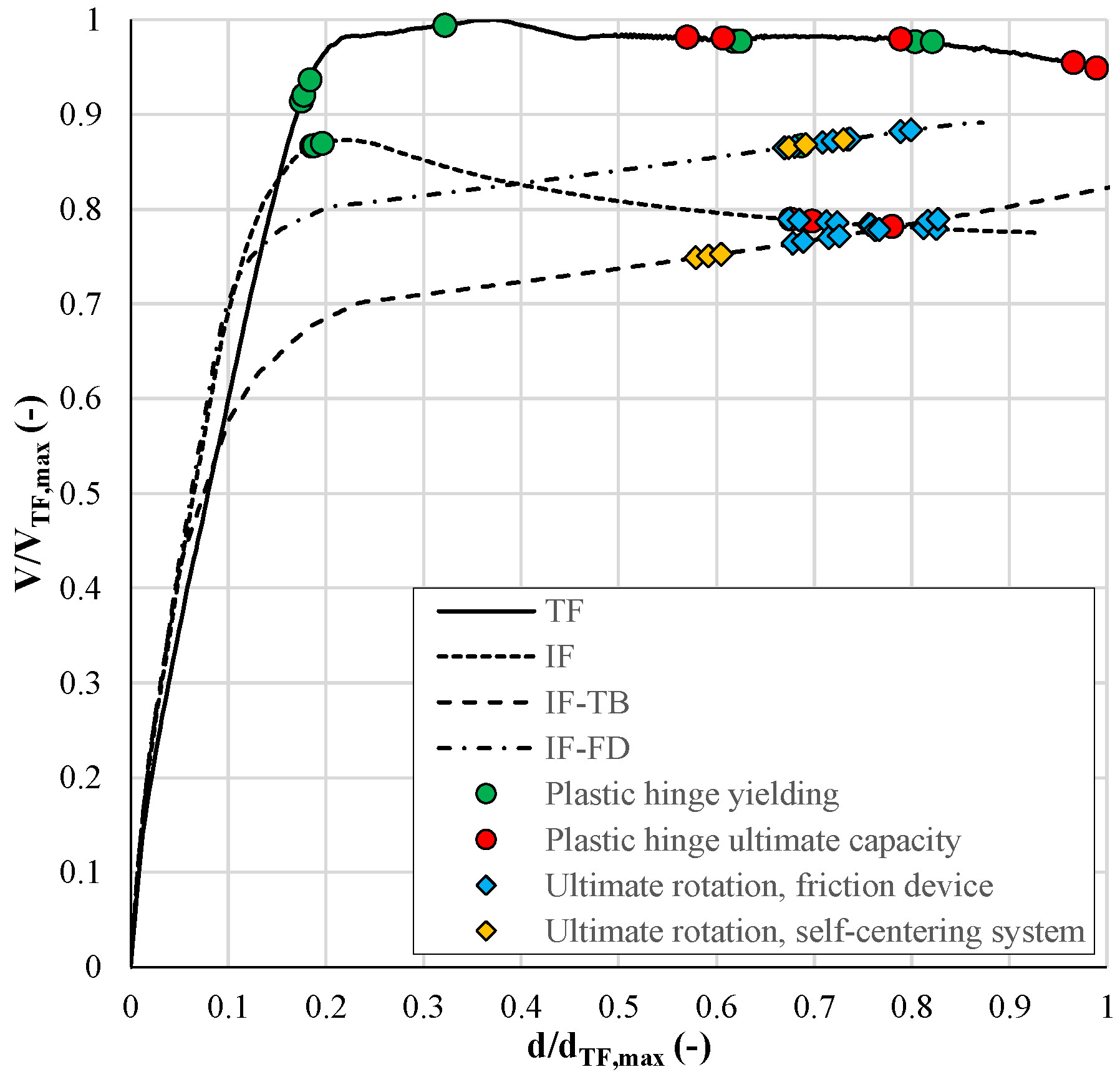
Figure 9 shows the comparison in capacity between the TF, which is the benchmark, and the dissipative frames, with and without self-centering systems. In particular, the graph reports the output of the pushover analyses in terms of base shear of each frame normalized to the maximum base shear of the TF (i.e., 390 kN) vs. top displacements of the frames normalized to the maximum top displacement of the TF (i.e., 0.46 m). Moreover, colored points are introduced to indicate the yielding and the ultimate rotations of the plastic hinges, deduced from the push-over analyses.
The comparison outlines that the frames equipped with BCCs exhibit higher initial stiffness due to the lengthened panel zones which make shorter columns. The maximum base shear is lower than in the TF because of a lower design value of the bending moment resistance of the friction devices, which is chosen in order to comply with the capacity design criteria. Therefore, the frames with friction dampers are designed assuming a behavior factor higher than in the TF.
Figure 8 also shows hardening branches after the yielding for both IF-TB and IF-FD; this response is achieved thanks to the stiffness of the CBC in the post-yielding branch of the constitutive behavior; this fact helps to solve the second-order effects. Conversely, the IF without self-centering systems, exhibits a post-yielding softening branch, which is mainly due to the damaged strength of the plastic hinge at the column base and to the elastic perfectly plastic behavior of the friction connection to the beam. In this regard, it has to be noted that the TF shows an elastic perfectly plastic capacity curve because the hardening behavior of the plastic hinge of the beam compensates for the P-effects. Finally, the RC structural members of IF-TB and IF-FD do not develop plastic hinges for global drift higher than 5% (i.e., top displacement equal to 0.3 m), which corresponds to d/d
TF,max ≈ 0.65 in the graph. For drift values higher than 5%, the friction devices attain their ultimate rotation, which is consistent with the design provisions.
Based on the observations above, it can be stated that the adoption of friction-damping devices in MRFs is useful for achieving a not-damaged response of the RC primary bearing structure for drifts up to the ultimate rotation of the system.
5.2. Global and Local Response from NLTHAs
The NLTHAs allow the evaluation of the structural response of each considered frame in global and local terms. In this regard,
Table 4 reports the averages and coefficients of variation (CV) of maximum inter-storey drift ratios (MIDRs) and residual inter-storey drift ratios (RISDRs), referred to the benchmark of the TF. It can be observed that the innovative frames exhibit similar MIDRs as TF with the exception of IF-TB, in which the presence of a re-centering system with lower value of yielding moment leads to an average increase in the MIDR on both the first and the second floors. Moreover, it is noteworthy to highlight that, in the absence of re-centering systems (i.e., in IF), the RIDR is more than two and four times than the TF at first and second level, respectively. Conversely, analyzing the results provided by IF-TB and IF-FD in terms of RIDR, it can be stated that the combined use of friction dampers at BCCs and self-centering systems allows for significantly limiting the RIDR. However, it should be also observed that in IF-TB and IF-FD an increment of the RIDR occurs at the second level. Among all proposed solutions, the best condition is definitely achieved when the friction dampers are adopted in both BCCs and CBCs, i.e., in IF-FD; this frame provides the lowest average MIDR and RIDRs comparable to those attained in the TF.
The NTHAs also allowed the assessment of the effective damage mitigation that can be achieved if friction devices and self-centering systems are introduced in the design of a RC MRF.
Figure 10 reports the moment-rotation curves of the IF vs. TF in the beam end section (
Figure 10a), at the column base (
Figure 10b), in the panel zone (
Figure 10c), and in the friction device (
Figure 10d). From
Figure 10a, it can be observed that the TF experiences plastic strains caused by the yielding of the lower rebars, while in the IF the beam behaves by following an elastic moment-rotation curve. From
Figure 10b, it is observed that the adoption of friction dampers only at BCCs does not prevent the IF to the formation of plastic hinges at the column base section. As regards the panel zone (
Figure 10c), it can be observed how the adoption of the BCC in the IF prevent the joint from loss of strength and stiffness that are significant in the TF instead. Therefore, in the IF, the damage of the panel zone is negligible, with limited development of cracks.
Finally,
Figure 11 reports the dissipated energy at the column base section (
Figure 11a) and in the re-centering devices (
Figure 11b) in IF-TB as well as IF-FD. It can be observed that, in both frames, the column base section behaves elastically. However, looking at
Figure 11b, it has to be noted that the connection in the IF-TB attains a lower maximum moment and a higher rotation, but the minor value of bending moment conducts to a feebler frame with high values of MIDRs. Moreover, the friction self-centering system in IF-FD dissipates a significant energy amount thanks to its moment-rotation diagram characterized by a flag-shape.
6. Conclusions
This paper investigates the efficacy of friction-damper devices at beam-to-column connections in RC frames in seismic areas, in the presence of self-centering systems at the column-base connections to the foundations.
The results of FE analyses conducted as feasibility studies are presented. Three different BCCs are proposed: with crossed slotted holes (BCC-1), with curved slotted holes (BCC-2), and curved slotted holes with Perfobond connectors (BCC-3). These solutions also differ for the device adopted as center of rotation: in the first solution, there is a pin while in the other two proposals, there is a T-stub with a weakened cross section. The two last solutions showed to be the most performing in terms of accuracy of the center of rotation position, stability of the hysteretic cycles, and amount of dissipated energy. As a preliminary analysis, BCC-2 is considered as the type of connection introduced in a two-storey and two-span MRF. The latter is studied by means of push-over analyses and NLTHAs considering different configurations: first of all, a traditional frame without friction dampers is modeled (TF), then, an innovative frame endowed with BCC-2 at joints is analysed (IF), and, finally, two frames equipped with self-centering devices are considered, i.e., with threaded bars used in combination with disk springs (IF-TB) and with added friction pads on the column splice (IF-FD). The capacity curves obtained from the push-over analyses showed that the introduction of friction dampers is effective in preventing the MRF from the damage of the RC primary structural elements for values of the drift up to the achievement of the ultimate capacity in rotation of the systems. The pushover analyses prove that the frames equipped with BCCs exhibit higher initial stiffness due to the lengthened panel zones which make shorter columns and, conversely, a lower value of design strength, which is set for complying with the capacity-design criteria. Moreover, the innovative frame without self-centering systems, exhibits a post-yielding softening branch, which is mainly due to the damaged strength attained in the plastic hinge at the base of the RC pillar. By contrast, the IF-TB and IF-FD exhibited a hardening-type behaviour after the yielding, which was guaranteed by the adequate stiffness of the post-yielding trend of the column-base connection, which allows it to overcome the second-order effects. The results of NTHAs outlined that the frame equipped with friction dampers at both BCCs and CBCs exhibits the most suitable seismic performance. As a matter of fact, the MIDRs and RIDRs are limited if compared to those of the TF and the RC primary bearing structure is prevented from severe damage because both beam end-section and column base-section behave elastically and the friction self-centering device allows the dissipation of a significant volume of energy thanks to its moment-rotation diagram characterized by a flag shape.
These results demonstrate the feasibility of the design of friction-damper devices in RC MRFs and their efficacy in improving the global and local structural response. As future developments, further analyses are under investigation for the assessment of the seismic response of MRFs endowed with BCC-3 and friction self-centering systems.
7. Patents
The Authors are inventors of a patent resulting from the work reported in this manuscript: Colajanni, P., La Mendola, L., Monaco, A., and Pagnotta, S. (inventors). Seismic dissipation system for building structures. Patent n. 102019000016742, 2019.
Author Contributions
Conceptualization, P.C., L.L.M., A.M. and S.P.; methodology, P.C., L.L.M., A.M. and S.P.; software, A.M. and S.P.; validation, A.M. and S.P.; writing—original draft preparation, A.M.; writing—review and editing, P.C., L.L.M., A.M. and S.P.; funding acquisition, P.C. and L.L.M. All authors have read and agreed to the published version of the manuscript.
Funding
This research was financially supported by SICILFERRO TORRENOVESE S.R.L. Company (Italy). Funding number: CON-0317, CUP: B74G20000100007. Date: 18 January 2021.
Institutional Review Board Statement
Not applicable.
Informed Consent Statement
Not applicable.
Data Availability Statement
The data presented in this study are available on request from the corresponding author. The data are not publicly available due to the privacy of the data.
Acknowledgments
The authors want to thank Mauro Scurria and Nicolò Cancelliere of SICILFERRO TORRENOVESE S.R.L. Company (Italy) for the helpful discussion on this research.
Conflicts of Interest
The authors declare no conflict of interest.
References
- Khoo, H.H.; Clifton, C.; Butterworth, J.; MacRae, G.; Ferguson, G. Influence of steel shim hardness on the Sliding Hinge Joint performance. J. Constr. Steel Res. 2012, 72, 119–129. [Google Scholar] [CrossRef]
- Khoo, H.H.; Clifton, C.; MacRae, G.; Zhou, H.; Ramhormozian, S. Proposed design models for the asymmetric friction connection. Earthq. Eng. Struct. Dyn. 2015, 44, 1309–1324. [Google Scholar] [CrossRef]
- Ramhormozian, S.; Clifton, G.C.; MacRae, G.A.; Khoo, H.H. The sliding hinge joint: Final steps towards an optimum low damage seismic-resistant steel system. Key Eng. 2018, 763, 751–760. [Google Scholar] [CrossRef]
- Latour, M.; Piluso, V.; Rizzano, G. Free from damage beam-to-column joints testing and design of DST connections with friction pads. Eng. Struct. 2015, 85, 219–233. [Google Scholar] [CrossRef]
- Latour, M.; D’Aniello, M.; Zimbru, M.; Rizzano, G.; Piluso, V.; Landolfo, R. Removable friction dampers for low-damage steel beam-to-column joint. Soil Dyn. Earthq. Eng. 2018, 115, 66–81. [Google Scholar] [CrossRef]
- Tsampras, G.; Sause, R.; Zhang, D.; Fleischman, R.B.; Restrepo, J.I.; Mar, D.; Maffei, J. Development of deformable connection for earthquake-resistant buildings to reduce floor accelerations and force responses. Earthq. Eng. Struct. Dyn. 2016, 45, 1473–1494. [Google Scholar] [CrossRef] [Green Version]
- Yang, T.S.; Popov, E.P. Experimental and Analytical Studies of Steel Connections and Energy Dissipators; UCB/EERC-95/13; College of Engineering, University of California: Berkeley, CA, USA, 1995. [Google Scholar]
- Francavilla, A.B.; Latour, M.; Piluso, V.; Rizzano, G. Design of Full-Strength Full-Ductility Extended End-Plate Beam-to-Column Joints. J. Constr. Steel Res. 2018, 148, 77–96. [Google Scholar] [CrossRef]
- Morgen, B.G.; Kurama, Y.C. A friction damper for post-tensioned precast concrete moment frames. PCI J. 2004, 49, 112–133. [Google Scholar] [CrossRef]
- Morgen, B.G.; Kurama, Y.C. Seismic response evaluation of posttensioned precast concrete frames with friction dampers. J. Struct. Eng. 2008, 134, 132–145. [Google Scholar] [CrossRef]
- Song, L.L.; Guo, T.; Chen, C. Experimental and numerical study of a self-centring prestressed concrete moment resisting frame connection with bolted web friction devices. Earthq. Eng. Struct. Dyn. 2014, 43, 529–545. [Google Scholar] [CrossRef]
- Tartaglia, R.; D’Aniello, M.; Rassati, G.A.; Swanson, J.; Landolfo, R. Influence of Composite Slab on the Nonlinear Response of Extended End-Plate Beam-to-Column Joints. Key Eng. 2017, 763, 818–825. [Google Scholar] [CrossRef]
- Tsampras, G.; Sause, R.; Fleischman, R.B.; Restrepo, J.I. Experimental study of deformable connection consisting of friction device and rubber bearings to connect floor system to lateral force resisting system. Earthq. Eng. Struct. Dyn. 2018, 47, 1032–1053. [Google Scholar] [CrossRef]
- Zhang, Z.; Fleischman, R.B.; Restrepo, J.I.; Guerrini, G.; Nema, A.; Zhang, D.; Shakya, U.; Tsampras, G.; Sause, R. Shake-table test performance of an inertial force-limiting floor anchorage system. Earthq. Eng. Struct. Dyn. 2018, 47, 1987–2011. [Google Scholar] [CrossRef]
- Colajanni, P.; La Mendola, L.; Monaco, A.; Pagnotta, S. Design of RC joints equipped with hybrid trussed beams and friction dampers. Eng. Struct. 2021, 227, 111442. [Google Scholar] [CrossRef]
- Colajanni, P.; La Mendola, L.; Monaco, A.; Pagnotta, S. Seismic Performance of Earthquake-Resilient RC Frames Made with HSTC Beams and Friction Damper Devices. J. Earthq. Eng. 2022, 26, 7787–7813. [Google Scholar] [CrossRef]
- Monaco, A.; Pagnotta, S.; Colajanni, P.; La Mendola, L. Innovative connections for steel-concrete-trussed beams: A patented solution. Procedia Struct. 2023, 44, 1925–1932. [Google Scholar] [CrossRef]
- Chisari, C.; Amadio, C. An experimental, numerical and analytical study of hybrid RC-encased steel joist beams subjected to shear. Eng. Struct. 2014, 61, 84–98. [Google Scholar] [CrossRef]
- Colajanni, P.; La Mendola, L.; Monaco, A. Experimental Investigation on the Shear Response of Precast Steel-Concrete Trussed Beams. J. Struct. Eng. 2017, 143, 04016156. [Google Scholar] [CrossRef]
- Ballarini, R.; La Mendola, L.; Le, J.; Monaco, A. Computational study of failure of hybrid steel trussed concrete beams. J. Struct. Eng. 2017, 143, 04017060. [Google Scholar] [CrossRef]
- Rayegani, A.; Nouri, G. Seismic collapse probability and life cycle cost assessment of isolated structures subjected to pounding with smart hybrid isolation system using a modified fuzzy based controller. Structures 2022, 44, 30–41. [Google Scholar] [CrossRef]
- Rayegani, A.; Nouri, G. Application of smart dampers for prevention of seismic pounding in isolated structures subjected to near-fault earthquakes. J. Earthq. Eng. 2022, 26, 4069–4084. [Google Scholar] [CrossRef]
- EN 1993:1-8:2005; Eurocode 3: Design of Steel Structures—Part 1–8: Design of Joints. CEN: Brussels, Belgium, 2005.
- ASCE/SEI 7-22; Minimum Design Loads and Associated Criteria for Buildings and Other Structures. American Society of Civil Engineers: Reston, VA, USA, 2022.
- Pagnotta, S.; Monaco, A.; Colajanni, P.; La Mendola, L. Experimental characterization of friction properties of materials for innovative beam-to-column dissipative connection for low-damage RC structures. Procedia Struct. 2023, 44, 1909–1916. [Google Scholar] [CrossRef]
- Colajanni, P.; Pagnotta, S. Friction-based beam-to-column connection for low-damage RC frames with hybrid trussed beams. Steel Compos. 2022, 45, 231–248. [Google Scholar]
- Abaqus. Abaqus, version 2016; Dassault Systèmes Simulia Corporation: Johnston, RI, USA, 2016.
- Eligehausen, R.; Popov, E.P.; Bertero, V.V. Local Bond Stress-Slip Relationships of Deformed Bars under Generalized Excitations; UCB/EERC-83/23; College of Engineering, University of California: Berkeley, CA, USA, 1983. [Google Scholar]
- D’Aniello, M.; Cassiano, D.; Landolfo, R. Simplified criteria for finite element modelling of European preloadable bolts. Steel Compos. 2017, 24, 643–658. [Google Scholar]
- Yun, X.; Gardner, L. Stress-strain curves for hot-rolled steels. J. Constr. Steel Res. 2017, 133, 36–46. [Google Scholar] [CrossRef]
- ACI 374.2R-13; Guide for Testing Reinforced Concrete Structural Elements under Slowly Applied Simulated Seismic Loads. American Concrete Institute: Farmington Hills, MI, USA, 2013.
- Latour, M.; Rizzano, G.; Santiago, A.; Da Silva, L.S. Experimental response of a low-yielding, self-centering, rocking column base joint with friction dampers. Soil Dyn. Earthq. Eng. 2019, 116, 580–592. [Google Scholar] [CrossRef]
- SeismoSoft 2020. SeismoStruct—A Computer Program for Static and Dynamic Nonlinear Analysis of Frames Structures. Available online: http://www.seismosoft.com (accessed on 5 March 2020).
- Colajanni, P.; Pagnotta, S.; Testa, G. Comparison of fully non-stationary artificial accelerogram generation methods in reproducing seismicity at a given site. Soil Dyn. Earthq. Eng. 2020, 133, 106135. [Google Scholar] [CrossRef]
- Vanmarcke, E.H.; Gasparini, D.A. Simulated earthquake ground motions. In Proceedings of the 4th International Conference on Structural Mechanics in Reactor Technology, San Francisco, CA, USA, 13 June 1977. [Google Scholar]
- Cacciola, P.; Colajanni, P.; Muscolino, G. Combination of modal responses consistent with seismic input representation. J. Struct. Eng. 2004, 130, 47–55. [Google Scholar] [CrossRef]
- Jennings, P.C.; Housner, G.W.; Tsai, C. Simulated earthquake motions for design purpose. In Proceedings of the 4th World Conference on Earthquake Engineering, Santiago, Chile, 13–18 January 1969. [Google Scholar]
- Sivaselvan, M.V.; Reinhorn, A.M. Hysteretic Models for Cyclic Behavior of Deteriorating Inelastic Structures; MCEER-99-0018; Multidisciplinary Center for Earthquake Engineering Research, State University of New York at Buffalo: Buffalo, CA, USA, 1999. [Google Scholar]
- Sivaselvan, M.V.; Reinhorn, A.M. Hysteretic models for deteriorating inelastic structures. J. Eng. Mech. 2000, 126, 633–640. [Google Scholar] [CrossRef]
- Mander, J.B.; Priestley, M.J.N.; Park, R. Theoretical stress-strain model for confined concrete. J. Struct. Eng. 1988, 114, 1804–1826. [Google Scholar] [CrossRef] [Green Version]
- Martinez-Rueda, J.E.; Elnashai, A.S. Confined concrete model under cyclic load. Mater. Struct. 1997, 30, 139–147. [Google Scholar] [CrossRef]
| Disclaimer/Publisher’s Note: The statements, opinions and data contained in all publications are solely those of the individual author(s) and contributor(s) and not of MDPI and/or the editor(s). MDPI and/or the editor(s) disclaim responsibility for any injury to people or property resulting from any ideas, methods, instructions or products referred to in the content. |
© 2023 by the authors. Licensee MDPI, Basel, Switzerland. This article is an open access article distributed under the terms and conditions of the Creative Commons Attribution (CC BY) license (https://creativecommons.org/licenses/by/4.0/).


