
Research on Roughness and Microhardness of C45 Material Using High-Speed Machining


Abstract
:1. Introduction
- Processing of predictions for the possibility of determining the quality of the surface of the machined components
- Identification of changes in surface roughness depending on the cutting speed
- Identification of the wear of the cutting edges due to the change in the cutting speed
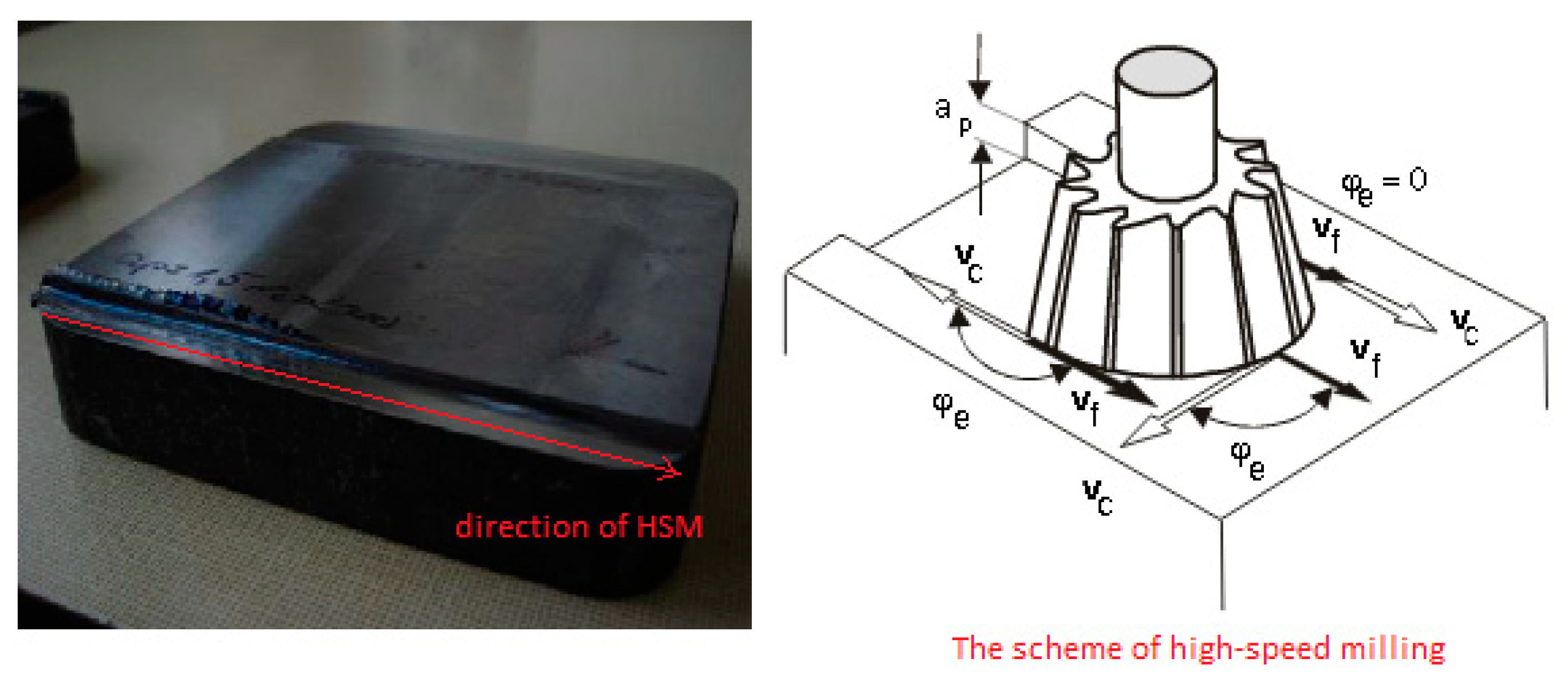
2. Materials and Methods
- —angle of plastic deformation limit [°]
- γn—tool angle of the face in the normal plane [°]
- -
- chip removal rate:
- -
- chip deformation:
- -
- shear speed:
- -
- deformation rate in the shear plane:
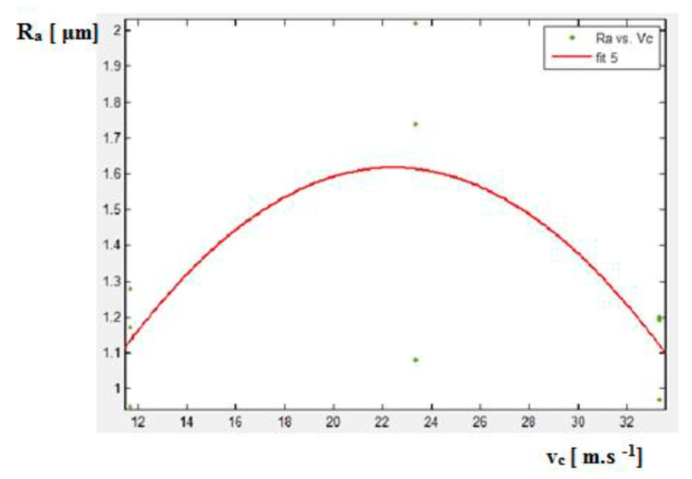
3. Results and Discussion
- p1 = −0.004176
- p2 = 0.1873
- p3 = −0.4834
- The shape of the chip does not change significantly with the cutting speed, and the chips are short and coiled,
- Chips have a small cross-section, the cut is interrupted, and high temperatures (up to 1500 °C) occur during milling due to large plastic deformations and chip friction,
- With increasing cutting speed, a short cutting time of individual grains was recorded,
- The generated heat decarbonizes the surface of the workpiece, so cracks and changes in the structure occur, unfavorable tensile residual stresses in the surface layer of the machined surface are created,
- Blunting of the individual cutting edges (cutter teeth) causes a loss of cutting ability.
4. Conclusions
- At 1400 m/min, the surface roughness was expected to have a decreasing tendency; however, it increased.
- A decreasing tendency was not recorded until at speeds of 1800 m/min, but during this process, the material already crept.
Author Contributions
Funding
Institutional Review Board Statement
Informed Consent Statement
Data Availability Statement
Conflicts of Interest
References
- Kuruc, M.; Vopát, T.; Peterka, J.; Necpal, M.; Šimna, V.; Milde, J.; Jurina, F. The Influence of Cutting Parameters on Plastic Deformation and Chip Compression during the Turning of C45 Medium Carbon Steel and 62SiMnCr4 Tool Steel. Materials 2022, 15, 585. [Google Scholar] [CrossRef] [PubMed]
- Zhang, J.; Liu, Z.; Liu, H.; Xu, X.; Outeiro, J.; Zhao, W. Fragmented chip formation mechanism in high-speed cutting from the perspective of stress wave effect. CIRP Ann. 2021, 70, 53–56. [Google Scholar] [CrossRef]
- Voß, R.; Henerichs, M.; Kuster, F.; Wegener, K. Chip Root Analysis after Machining Carbon Fiber Reinforced Plastics (CFRP) at Different Fiber Orientations. Procedia CIRP 2014, 14, 217–222. [Google Scholar] [CrossRef] [Green Version]
- Denkena, B.; Breidenstein, B.; Krödel, A.; Prasanthan, V. Chip formation in machining hybrid components of SAE1020 and SAE5140. Prod. Eng. 2021, 15, 187–197. [Google Scholar] [CrossRef]
- Kim, D.G.; Yang, S.H. Efficient Analysis of CFRP Cutting Force and Chip Formation Based on Cutting Force Models under Various Cutting Conditions. Int. J. Precis. Eng. Manuf. 2023, 24, 1235–1251. [Google Scholar] [CrossRef]
- Murčinková, Z.; Vasilko, K.; Murčinko, J. Analysis of wide-range dependence of cutting parameters and the coating impact in deformation zone. Indian J. Eng. Mater. Sci. 2016, 23, 254–260. [Google Scholar]
- Oosthuizen, G.A.; Nunco, K.; Conradie, P.J.T.; Dimitrov, D.M. The effect of cutting parameters on surface integrity in milling Ti6Al4V. S. Afr. J. Ind. Eng. 2016, 27, 115–123. [Google Scholar] [CrossRef] [Green Version]
- Iqbal, A.; Zhao, G.; Zaini, J.; He, N.; Nauman, M.M.; Jamil, M.; Suhaimi, H. Sustainable hole-making in a titanium alloy using throttle and evaporative cryogenic cooling and micro-lubrication. J. Manuf. Process. 2021, 67, 212–225. [Google Scholar] [CrossRef]
- Hashmi, K.H.; Zakria, G.; Raza, M.B.; Khalil, S. Optimization of process parameters for high speed machining of Ti-6Al-4V using response surface methodology. Int. J. Adv. Manuf. Technol. 2016, 85, 1847–1856. [Google Scholar] [CrossRef]
- Abbas, A.T.; Sharma, N.; Anwar, S.; Hashmi, F.H.; Jamil, M.; Hegab, H. Towards optimization of surface roughness and productivity aspects during high-speed machining of Ti-6Al-4V. Materials 2019, 12, 3749. [Google Scholar] [CrossRef] [Green Version]
- Lukic, D.; Cep, R.; Vukman, J.; Antic, A.; Djurdjev, M.; Milosevic, M. Multi-Criteria Selection of the Optimal Parameters for High-Speed Machining of Aluminum Alloy Al7075 Thin-Walled Parts. Metals 2020, 10, 1570. [Google Scholar] [CrossRef]
- Ghasemi, A.H.; Khorasani, A.M.; Gibson, I. Investigation on the effect of a pre-center drill hole and tool material on thrust force, surface roughness, and cylindricity in the drilling of Al7075. Materials 2018, 11, 140. [Google Scholar] [CrossRef] [Green Version]
- Muhammad, A.; Kumar Gupta, M.; Mikołajczyk, T.; Pimenov, D.Y.; Giasin, K. Effect of Tool Coating and Cutting Parameters on Surface Roughness and Burr Formation during Micromilling of Inconel 718. Metals 2021, 11, 167. [Google Scholar] [CrossRef]
- Jeyapandiarajan, P.; Xavior, A. Influence of cutting condition on machinability aspects of Inconel 718. J. Eng. Res. 2019, 7, 315–332. [Google Scholar]
- Savković, B.; Kovač, P.; Stoić, A.; Dudić, B. Optimization of Machining Parameters Using the Taguchi and ANOVA Analysis in the Face Milling of Aluminum Alloys AL7075. Teh. Vjesn. 2020, 27, 1221–1228. [Google Scholar]
- Košarac, A.; Šikuljak, L.; Obradović, Č.; Mlađenović, C.; Zeljković, M. Cutting parameters influence on surface roughness in AL 7075 milling. In Proceedings of the 2020 19th International Symposium INFOTEH-JAHORINA (INFOTEH), Sarajevo, Bosnia and Herzegovina, 18–20 March 2020; pp. 1–6. [Google Scholar]
- Khawaja, A.H.; Jahanzaib, M.; Cheema, T.A. High-speed machining parametric optimization of 15CDV6 HSLA steel under minimum quantity and flood lubrication. Adv. Prod. Eng. Manag. 2020, 15, 403–415. [Google Scholar] [CrossRef]
- Jamil, M.; He, N.; Huang, X.; Zhao, W.; Gupta, M.K.; Khan, A.M. Measurement of machining characteristics under novel dry ice blasting cooling assisted milling of AISI 52100 tool steel. Measurement 2022, 191, 110821. [Google Scholar] [CrossRef]
- Jamil, M.; He, N.; Zhao, W.; Khan, A.M.; Xiang, H.; Gupta, M.K.; Iqbal, A. A novel low-pressure hybrid dry ice blasting system for improving the tribological and machining characteristics of AISI-52100 tool steel. J. Manuf. Process. 2022, 80, 152–160. [Google Scholar] [CrossRef]
- Tamizharasan, T.; Kumar, S. Optimization of cutting insert geometry using DEFORM-3 D: Numerical simulation and experimental validation. Int. J. Simul. Model. 2012, 11, 65–76. [Google Scholar] [CrossRef]
- Kang, W.T.; Derani, M.N.; Ratnam, M.M. Effect of vibration on surface roughness in finish turning: Simulation study. Int. J. Simul. Model. 2020, 19, 595–606. [Google Scholar] [CrossRef]
- Simunovic, G.; Simunovic, K.; Saric, T. Modelling and simulation of surface roughness in face milling. Int. J. Simul. Model. 2013, 12, 141–153. [Google Scholar] [CrossRef]
- Behunova, A.; Behun, M.; Knapcikova, L. Simulation software support of manufacturing processes in engineering industry. TEM J. 2018, 7, 849–853. [Google Scholar]
- Tsao, C.C. Grey–Taguchi method to optimize the milling parameters of aluminum alloy. Int. J. Adv. Manuf. Technol. 2009, 40, 41–48. [Google Scholar] [CrossRef]
- Ribeiro, J.; Lopes, H.; Queijo, L.; Figueiredo, D. Optimization of cutting parameters to minimize the surface roughness in the end milling process using the Taguchi method. Period. Polytech. Mech. Eng. 2017, 61, 30–35. [Google Scholar] [CrossRef]
- Lan, T.S.; Chuang, K.C.; Chen, Y.M. Optimization of machining parameters using fuzzy Taguchi method for reducing tool wear. Appl. Sci. 2018, 8, 1011. [Google Scholar] [CrossRef] [Green Version]
- Kumar, S.; Singh, D.; Kalsi, N.S. Experimental investigations of surface roughness of Inconel 718 under different machining conditions. Mater. Today Proc. 2017, 4, 1179–1185. [Google Scholar] [CrossRef]
- Kočiško, M.; Bašistová, A.; Tkáč, J. Analysis regarding Dynamic Parameters of the Milling Head Bearings. TEM J. 2019, 8, 872–878. [Google Scholar]
- Valíček, J.; Harničárová, M.; Kopal, I.; Palková, Z.; Kušnerová, M.; Panda, A.; Šepelák, V. Identification of Upper and Lower Level Yield strength in Materials. Materials 2017, 10, 982. [Google Scholar] [CrossRef] [Green Version]
- Kováč, M.; Peterka, J. Selected 5-axis Strategies for High-speed milling of Thin-walled Parts. Appl. Mech. Mater. 2014, 467, 466–469. [Google Scholar] [CrossRef]
- Ravai Nagy, S.; Paşca, I.; Lobonțiu, M.; Banica, M. Experimental research of effective cutting speed influence on surface roughness in ball end milling of C45 material with hardness 34 HRC. Appl. Mech. Mater. 2014, 657, 53–57. [Google Scholar] [CrossRef]
- Djunaidi, A.A.; Rachmat, H.; Atmaja, D.S.E. Optimization of Cutting Parameters to Minimize Surface Roughness of C45 Steel in Turning Process on S530 X 1000 Lathe Using Taguchi Method. Eproceedings Eng. 2020, 7, 1823–1828. [Google Scholar]
- Bouchareb, A.; Lagred, A.; Amirat, A. Effect of the interaction between depth of cut and height-to-width ratio of a workpiece on vibration amplitude during face milling of C45 steel. Int. J. Adv. Manuf. Technol. 2019, 104, 1221–1227. [Google Scholar] [CrossRef]
- Jurko, J.; Panda, A. Change of Material Deformation under the Machined Surface when Drilling Steel C45 and DIN 1.4301. Appl. Mech. Mater. 2014, 459, 428–431. [Google Scholar] [CrossRef]
- Tanigawa, D.; Abe, N.; Tsukamoto, M.; Hayashi, Y.; Yamazaki, H.; Tatsumi, Y.; Yoneyama, M. The effect of particle size on the heat affected zone during laser cladding of Ni–Cr–Si–B alloy on C45 carbon steel. Opt. Lasers Eng. 2018, 101, 23–27. [Google Scholar] [CrossRef]
- Wójcik, R.; Nadolny, K. The effect of the grinding wheel modification on the state of the workpiece surface layer after internal cylindrical grinding of steel C45. Proc. Inst. Mech. Eng. Part E J. Process. Mech. Eng. 2017, 231, 1162–1173. [Google Scholar] [CrossRef]
- Skoczylas, A. Geometric structure of the C45 steel surface after centrifugal burnishing and perpendicular shot peening. Adv. Sci. Technol. 2018, 12, 20–28. [Google Scholar] [CrossRef]
- Marcinkova, M. Study of the Formation of Deformations in the Cutting Zone during High-Speed Machining and Their Experimental Verification. Master’s Thesis, Technical University of Kosice, Presov, Slovakia, 2015. [Google Scholar]
- Alam, S.T.; Tomal, A.A.; Nayeem, M.K. High-speed machining of Ti–6Al–4V: RSM-GA based optimization of surface roughness and MRR. Results Eng. 2023, 17, 100873. [Google Scholar] [CrossRef]
- Bałon, P.; Rejman, E.; Kiełbasa, B.; Smusz, R. Using HSM technology in machining of thin-walled aircraft structures. Acta Mech. Autom. 2022, 16, 27–33. [Google Scholar] [CrossRef]
- Fayzimatov, S.; Abdullaev, B. Ensure the quality of the surface layer of parts in high-speed end milling of hardened steels. In Proceedings of the E3S Web of Conferences, Moscow, Russia, 20–22 April 2023; Volume 383, p. 04067. [Google Scholar]
- Jain, V.K. Advanced Machining Science; CRC Press: Boca Raton, FL, USA, 2022. [Google Scholar]
- Vasilko, K. Theory and Practice of Chip Machining (Teória a Prax Trieskového Obrábania); Cofin: Presov, Slovakia, 2009. [Google Scholar]
- DMG MORI-HSC 105 Linear-Technical Data. Available online: https://www.exfactory.com/Literature/DMG/HSC75-PDFa.pdf (accessed on 30 May 2023).


| Experiment Alternatives—Cutting Speed [m/min] | |||||||||
|---|---|---|---|---|---|---|---|---|---|
| 700 | 1400 | 2000 | |||||||
| Spindle Speed n [min−1] | 13,934 | 27,866 | 39,808 | ||||||
| Feed Speed vf [mm/min] | 5573.6 | 11,146.4 | 15,923.2 | ||||||
| Radial depth of cut ae [mm] | 4 | 4 | 4 | ||||||
| Actual chip thickness h [mm] | 0.1 | ||||||||
| Medium chip thickness hm [mm] | 0.047 | ||||||||
| Maximum angle of the cutter tooth mesh [°] | 60 | ||||||||
| Specification of parameter “ap” | |||||||||
| Experiment alternatives—cutting speed [m/min] | |||||||||
| 700 | 1400 | 2000 | |||||||
| Axial depth of cut ap [mm] | 0.5 | 1 | 1.5 | 0.5 | 1 | 1.5 | 0.5 | 1 | 1.5 |
| Section S [mm2] | 0.05 | 0.1 | 0.15 | 0.05 | 0.1 | 0.15 | 0.05 | 0.1 | 0.15 |
| Chip width b [mm] | 0.5 | 1 | 1.5 | 0.5 | 1 | 1.5 | 0.5 | 1 | 1.5 |
| Maximal section Smax [mm2] | 0.05 | 0.1 | 0.15 | 0.05 | 0.1 | 0.15 | 0.05 | 0.1 | 0.15 |
| Average section Sm [mm2] | 0.023 | 0.047 | 0.070 | 0.023 | 0.047 | 0.070 | 0.023 | 0.047 | 0.070 |
| Specification of used material—C45 | |||||||||
| Tensile strength Rm [MPa] | 570 | ||||||||
| Yield strength [MPa] | 325 | ||||||||
| Density [kg.m−3] | 7870 | ||||||||
| Thermal coefficient of expansion [K−1] | 11.6 × 10⁻⁶ | ||||||||
| Thermal conductivity [W.m−1.K−1] | 49 | ||||||||
| Work area x-y-z [mm] | 1110 × 800 × 600 |
| Swivel axes (A/B) | –10/+110 |
| Rotary axis (C) | 360 |
| Maximum spindle speed [rpm] | 40,000 |
| Maximum feed rate [mm/min] | 90,000 |
| Maximum tool length [mm] | 300 |
| Maximum tool diameter [mm] | 140 |
| Power diagram |  |
| vc = 700 (m/min) | vc = 1400 (m/min) | vc = 2000 (m/min) | ||||||||||||||||
|---|---|---|---|---|---|---|---|---|---|---|---|---|---|---|---|---|---|---|
| Before HSM | After HSM | Before HSM | After HSM | Before HSM | After HSM | |||||||||||||
| ap (mm) | ap (mm) | ap (mm) | ap (mm) | ap (mm) | ap (mm) | |||||||||||||
| 0.5 | 1 | 1.5 | 0.5 | 1 | 1.5 | 0.5 | 1 | 1.5 | 0.5 | 1 | 1.5 | 0.5 | 1 | 1.5 | 0.5 | 1 | 1.5 | |
| A | 198.2 | 261.8 | 218.4 | 210.1 | 206.0 | 212.7 | 245.8 | 179.0 | 210.7 | 187.1 | 215.6 | 175.2 | 181.9 | 764.4 | 224.0 | 221.3 | 624.7 | 303.3 |
| B | 201.3 | 177.2 | 232.8 | 205.2 | 262.1 | 207.5 | 225.4 | 168.3 | 208.5 | 193.3 | 162.7 | 219.1 | 172.5 | 279.3 | 199.3 | 215.0 | 270.3 | 222.5 |
| C | 213.0 | 183.7 | 192.5 | 203.5 | 217.3 | 200.1 | 218.4 | 187.9 | 228.7 | 208.8 | 185.4 | 210.3 | 210.1 | 210.6 | 210.2 | 217.8 | 204.7 | 240.2 |
| Parameter | Values—Experiment Alternatives | ||
|---|---|---|---|
| vc = 700 [m/min] | vc = 1400 [m/min] | vc = 2000 [m/min] | |
| Chip compression | 1.16 | ||
| plastic deformation limit angle | 47° | ||
| chip removal rate | 681.3 [m/min] | 1362.6 [m/min] | 1946.6 [m/min] |
| chip deformation | 1.32° | ||
| shear speed | 924 [m/min] | 1848 [m/min] | 2640 [m/min] |
| deformation rate in the shear plane | 9240 [s−1] | 18,480 [s−1] | 26,400 [s−1] |
| Depth of Cut [mm] | Before HSM | After HSM | Chip |
|---|---|---|---|
| 0.5 |  |  |  |
| 1 |  |  |  |
| 1.5 |  |  | 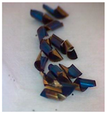 |
| Depth of Cut [mm] | Before HSM | After HSM | Chip |
|---|---|---|---|
| 0.5 |  |  |  |
| 1 |  |  | 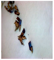 |
| 1.5 |  |  |  |
| Depth of Cut [mm] | Before HSM | After HSM | Chip |
|---|---|---|---|
| 0.5 |  |  |  |
| 1 |  |  |  |
| 1.5 |  |  |  |
Disclaimer/Publisher’s Note: The statements, opinions and data contained in all publications are solely those of the individual author(s) and contributor(s) and not of MDPI and/or the editor(s). MDPI and/or the editor(s) disclaim responsibility for any injury to people or property resulting from any ideas, methods, instructions or products referred to in the content. |
© 2023 by the authors. Licensee MDPI, Basel, Switzerland. This article is an open access article distributed under the terms and conditions of the Creative Commons Attribution (CC BY) license (https://creativecommons.org/licenses/by/4.0/).
Share and Cite
Duplak, J.; Duplakova, D.; Zajac, J. Research on Roughness and Microhardness of C45 Material Using High-Speed Machining. Appl. Sci. 2023, 13, 7851. https://doi.org/10.3390/app13137851
Duplak J, Duplakova D, Zajac J. Research on Roughness and Microhardness of C45 Material Using High-Speed Machining. Applied Sciences. 2023; 13(13):7851. https://doi.org/10.3390/app13137851
Chicago/Turabian StyleDuplak, Jan, Darina Duplakova, and Jozef Zajac. 2023. "Research on Roughness and Microhardness of C45 Material Using High-Speed Machining" Applied Sciences 13, no. 13: 7851. https://doi.org/10.3390/app13137851
APA StyleDuplak, J., Duplakova, D., & Zajac, J. (2023). Research on Roughness and Microhardness of C45 Material Using High-Speed Machining. Applied Sciences, 13(13), 7851. https://doi.org/10.3390/app13137851