Article

Monitoring of Surgically Treated Upper Arm Fracture by Implanted Antenna at 402 MHz

by
Wael Zeinelabedeen
* and
Rasime Uyguroglu
Department of Electrical and Electronic Engineering, Eastern Mediterranean University, Famagusta 99628, Turkey
*
Author to whom correspondence should be addressed.
Appl. Sci. 2023, 13(13), 7786; https://doi.org/10.3390/app13137786
Submission received: 16 May 2023 / Revised: 31 May 2023 / Accepted: 23 June 2023 / Published: 30 June 2023
(This article belongs to the Section Electrical, Electronics and Communications Engineering)

Abstract

:
Remote patient monitoring aims to reduce non-essential visits to clinics and hospitals, monitor high-risk patients outside clinical settings, and optimize clinical staff utilization. This paper proposes a new monitoring application for surgically treated upper arm fractures. The humerus fracture should be healed within four to six weeks. Traditional monitoring is conducted through repeated X-ray images and visits to clinical laboratories or hospitals. Our goal is to avoid the expected drawbacks due to repeated exposure to X-rays, such as vomiting, bleeding, fainting, and sometimes the risk of cancer. Furthermore, this study aims to improve the patient’s quality of life during the treatment period by monitoring them at home. The technique depends on implanting a 116 mm length half-wave dipole antenna in the fractured arm and recording the reflection coefficient and the transmitted power at the far-field of it outside the body at 402 MHz. The fracture is represented by an extra layer added to the humerus, which increases the loss of electromagnetic field in the human tissue and then reduces the value of the transmitted power. The existence of fractures shows a change in the transmitted average power densities (APDs) in the range of 11.54% to 15.75%, based on the fracture types, and an increase in reflection coefficients in the range of −22.35 dB to −22.65 dB compared to the normal bone, which monitors the bone healing status. The standard limit of the specific absorption rate was taken into account to guarantee the safety of the human body. Different fracture types were considered and monitored, and CST Microwave Studio was used for simulation. The technique was verified experimentally by measurements carried out on a lifeless front leg animal model. The technique can also be used for the monitoring of ulna and tibia fractures.

1. Introduction

The spread of the COVID-19 pandemic in the last few years and its effects on the worldwide healthcare infrastructure has highlighted the need to adopt innovative healthcare technology and remote patient monitoring applications.
Remote patient monitoring applications target patients whose health status requires them to be monitored continuously. Such patients are diagnosed with chronic diseases, movement disability issues, post-surgery concerns, and other disorders. The aim of remote monitoring applications is to support the ordinary life of patients as comfortably as possible.
The remote patient monitoring system is composed of three units and works in three different phases. The data-collecting device is an implanted or wearable device capable of collecting and transmitting physiological signals outside the body to the data handling unit or monitoring device. Consecutively, the signal is processed and transmitted to the end terminal computer or dedicated device at the hospital or clinical laboratory. The communication network controls the data transfer between the different units using wireless technology [1].
Classic healthcare technologies are commonly used for the medical diagnosis of cancer, bone imaging, etc. The technologies include mammography; computed tomography (CT), which was described by Cormack in 1963 using the X-ray discovered by Rontgen in 1895; magnetic resonance imaging (MRI) using magnetic field, which was first tested in 1980; and sonography using ultrasound, which was first produced commercially in 1965. Although they provide images with a high contrast between different human tissues and good spatial resolution, conventional technologies have their drawbacks [2].
As a result of their bulky machinery and high manufacturing cost, MRI systems are not widely available in all hospitals. The scan time and post-processing time of the signals are relatively long. Mammography and CT scan units use ionized radiation, which is harmful to human tissues and increases the risk of cancer in certain conditions. Furthermore, the examinations associated with the mammography system are painful and must be accepted by patients. The ultrasound technique is preferable in medical diagnosis and imaging as there is no ionization. However, the penetration through bone tissue and air is short due to the strong reflection associated with it.
In contrast to the drawbacks and risks associated with conventional techniques in healthcare, microwave technology uses non-ionizing radiation. Compared to mammography and CT scan, the used electromagnetic waves are less harmful to human tissues. Moreover, microwaves demonstrate good penetration through all human tissues at low frequencies, especially in the medical implant communication system (MICS) band. Such an advantage is not available in the ultrasound technique. Wide bandwidth microwave signals provide high-resolution medical imaging. Additionally, microwaves combine diagnosis and wireless transmission signals within the same frequency range, which is not possible when using other traditional technologies.
With the advances in wireless communication in bioengineering, antenna technology has become progressively more important in applications of healthcare and remote patient monitoring systems. Healthcare monitoring is based on body-centric wireless communications (BSWCs) and includes wearable and implantable monitoring systems [3]. When designing an antenna for the implanted device, the electrical properties of the surrounding biological tissues must be considered. The quality of the implanted antenna is characterized by the amount of power transmitted outside the body [4,5,6,7]. Implanted medical devices have become essential in a wide range of medical applications, such as intracranial pressure monitoring, continuous blood pressure measurements, glucose monitoring, and heartbeat monitoring and control [8,9,10].
The medical implanted device includes electronics, sensors, battery, and antenna. All these components must be fit into housing that has an ergonomic shape, which requires dense packaging and good integration of the components. Miniaturization techniques have to be considered in the design and manufacturing procedures of the antenna as it occupies most of the implanted device’s volume.
Early studies in antenna miniaturization show that the efficiency and impedance of bandwidth are reduced as a result of reducing the whole size of the antenna. Many recent investigations have been carried out to reduce the overall size of different types of antennas while keeping satisfactory matching properties and acceptable bandwidth. These techniques mainly depend on changing the physical and electrical properties of the antenna. Planar antennas can be miniaturized by using high permittivity substrate, reactive components, and shorting pins. Topology-based techniques design a larger radiating structure by the efficient use of the available volume or space, such as meander and fractal antennas [11].
More recently, metamaterials are composite media that can be engineered to exhibit unique electromagnetic properties. It is worth mentioning that these metamaterials are artificial structures composed of arrangements of periodic or non-periodic homogeneous metal structures of a size much smaller than the guided wavelength on the surface of dielectric material. The permittivity and permeability of the metamaterial depends on this created structure. Due to the unique electromagnetic properties that are not available in natural materials, antennas with novel characteristics, enhanced performance, and a compact size can be designed [12,13].
This study proposes a solution by implanted antenna for the monitoring of humerus fracture healing, which should be healed within 6 weeks. The traditional monitoring is usually processed by repeated X-ray images and visits to clinical laboratories or hospitals, which is difficult, especially for elderly patients. We aim to avoid this difficulty and comfort the patient during the treatment period. This fracture is treated surgically, and the proposed monitoring technique is used by implanting a half-wave dipole antenna between the fractured shaft and the muscle tissue within the human body during the surgical operation. The change in the transmission of APD in cases of recovered and fractured bone is used for monitoring the healing status. The operating frequency was selected at 402 MHz to save a number of electromagnetic (EM) losses within the human tissues as the losses reduce at low frequencies. Two different topologies of the half-wave dipole antenna were tested.
A proposed model for the post-surgical treated human humerus was presented. This model includes a metal fixation plate to hold the fractured bone in its place and a medical splint layer to hold and save the upper arm during the healing period. Towards this end, different positions of the fracture were considered.
The monitoring technique was simulated by CST Microwave studio for the common types of fractures and showed good results by planar and wire half-wave dipole antennas. The specific absorption rate (SAR) was simulated, and the excitation signal was selected to satisfy the SAR standard limit and to be sure that the implanted antenna is safe for human tissues. Measurement and verification were carried out on lifeless animal models. The results of the measurements were in good agreement with the simulation.
The rest of the paper is organized as follows: Section 2 introduces the proposed monitoring application. The model and monitoring method are illustrated in Section 3. The simulations are presented in Section 4. Section 5 demonstrates the measurements and validation. Finally, Section 6 concludes the paper.

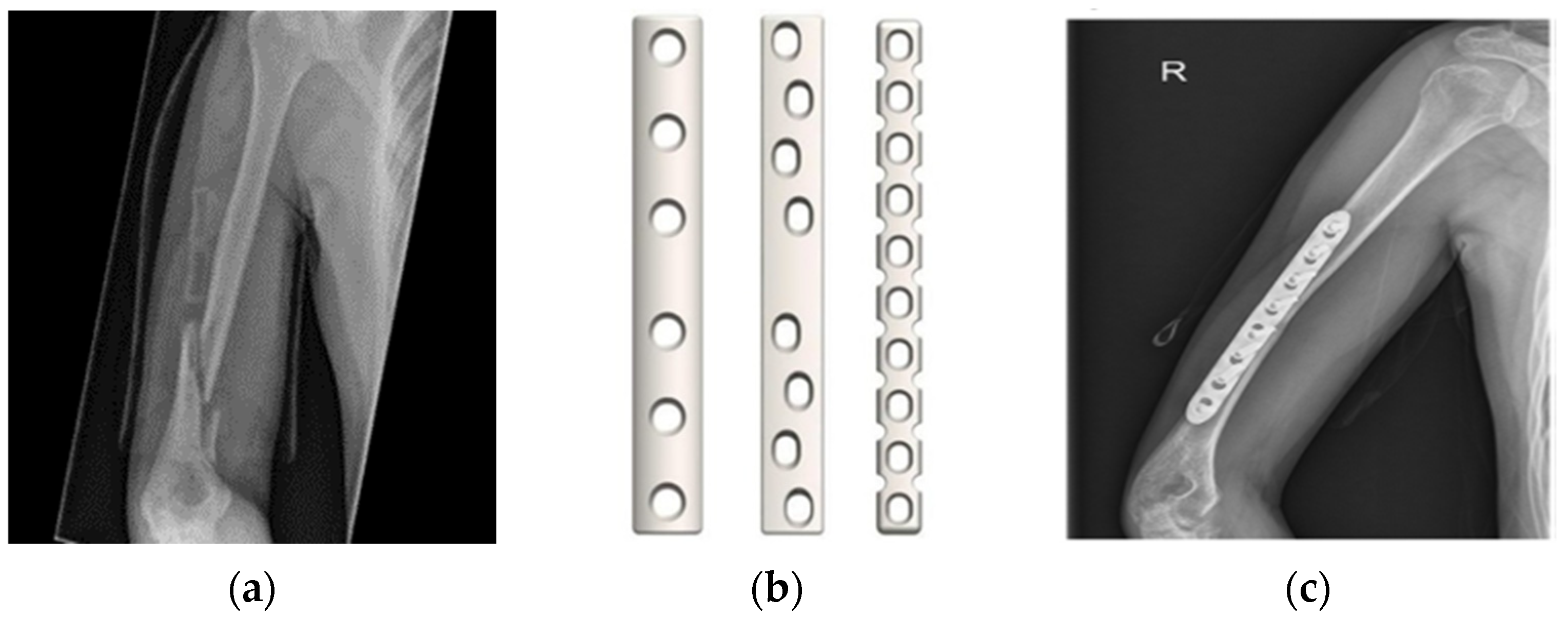
2. The Monitoring Application

The human’s upper arm (humerus) is the long bone that runs from the shoulder to the elbow. The humerus shaft fracture is one that is localized in the mid-portion of the upper arm as shown in Figure 1a. This fracture is a common injury and is always a consequence of a fall with an outstretched hand, or a car accident. The treatment can be with or without surgery according to the fracture pattern and associated injury. A temporary splint extending from the shoulder to the forearm and holding the elbow bent at 90 degrees can be used for the initial management of the fracture. Non-operative treatment usually includes the placement of fracture bracing that will be replaced by a cylindrical brace (Sarmiento brace) three to four weeks later that fits the upper arm while leaving the elbow free. Surgery treatment, on the other hand, usually involves internal fixation of the fragments with plates that are used to hold the fractured bone in its place until healing is completed (Figure 1b), or with screws or a nail [14]. Figure 1c shows the right upper arm after installing the fixation plate surgically.
The post-surgery follow-up of the fracture is usually conducted by X-ray images, and the patient is monitored at the clinic by serial radiographs at ten days, three weeks, six weeks, and as needed thereafter [15]. The proposed monitoring application in this study saves X-ray exposure and visits to the clinic by monitoring the patient at home. In his health care application, an antenna is implanted within the humerus, and the value of the return loss and transmitted power at its far field is recorded. Human tissue is a lossy medium for electromagnetic waves, and the fracture adds extra lossy tissues. The application considers a safe value of the excitation signal which produces an acceptable level of specific absorption rate (SAR) within the tissue. The difference in transmitted power between the normal and the fracture cases monitors the bone healing status [16].

3. The Method

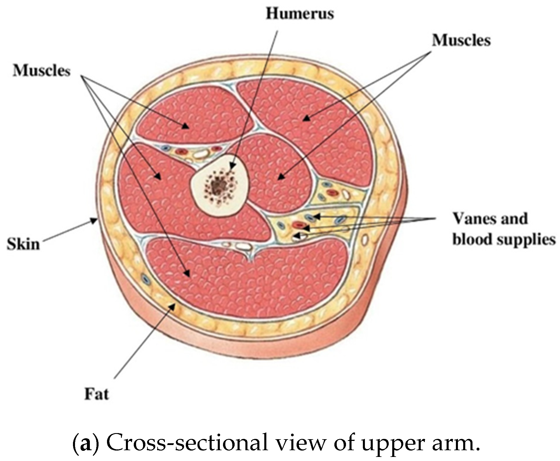
3.1. The Upper Arm Model

The human upper arm is composed of the humerus surrounded by a group of muscles, followed by fat and skin. Blood supplies and vanes are included between the muscles. Figure 2a shows a cross-sectional view of the upper arm. An approximated cylindrical model of the human upper arm is proposed for the simulation of this monitoring technique, which is shown in Figure 2b. The model is composed of concentric cylindrical layers of bone, muscle, fat, skin, and, finally, the splint layer, which is used to hold the fractured bone in place during the healing period. A metallic fixation plate in Figure 1b is surgically used to fix the fracture in place. The fracture is modelled by an additional layer in the bone. A circular disc layer perpendicular to the bone shaft represents the transverse fracture, and an elliptical disc layer with an angle including the bone axis represents the oblique fractured humerus.
As the proposed antenna is a half-wave dipole, and its position is centered at the fracture, the location of the fracture must be away from the shoulder and the elbow joint by one quarter of the wavelength for the antenna to be in a suitable place. In general, the common position of arm fractures is in the middle shaft of the humerus.
Table 1 summarizes the dimensions of the tissue model [17] in addition to the medical splint and fixation plate dimensions. Normal and fractured humerus models are simulated by CST microwave studio at 402 MHz.

3.2. Fracture Monitoring

The monitoring application records the transmitted power density at the far field of an implanted antenna in the human humerus. The antenna is implanted at the boundary between the fractured bone and the muscle layer. In the case of a fractured humerus, an additional layer represents the fracture in the upper arm model shown in Figure 1b. The bleeding in the fractured bone area leads to inflammation, followed by the clotting of blood at the fracture site. Bone production begins when the clotted blood is replaced with cartilage and fibrous tissues. As healing grows, the fibrous tissue is replaced with new hard bone tissue. The electrical properties of the fracture layer change from blood properties at the beginning of fracture time to the new normal bone after the healing completeness. This change affects the amount of loss from the radiated power of the antenna and then the transmitted power density outside the body. As the bone heals, the transmitted APD from the implanted antenna to outside the body increases gradually until a normal value is reached when the bone fracture is completely recovered. The bone status during the monitoring period can be expressed by the difference in transmitted APD between the normal and fractured bone. The transmitted power is received by the monitoring device at home which, in turn, retransmits it again to the clinical laboratory or hospital for following up, adjustment, or changing the healthcare plan if needed.

3.3. Biocompatibility

Implantable antennas must be biocompatible to ensure patient safety and prevent implant rejection. Isolating the metallic radiator from the human tissue by employing a biocompatible substrate and inserting a thin layer of low-loss biocompatible coating is a technique used to preserve the biocompatibility of the antenna (biocompatible encapsulation) [18].
Antennas insulation by capsules is used in capsule endoscopy for the diagnosis of the human digestive system. A swallowable electronic radio-telemetry capsule was first developed in 1957 and was used to measure temperature and blood pressure [19].
Various designs have been used in the related literature for biocompatible antennas. Table 2 lists some of the antenna types, the operating frequency, and antenna parameters.

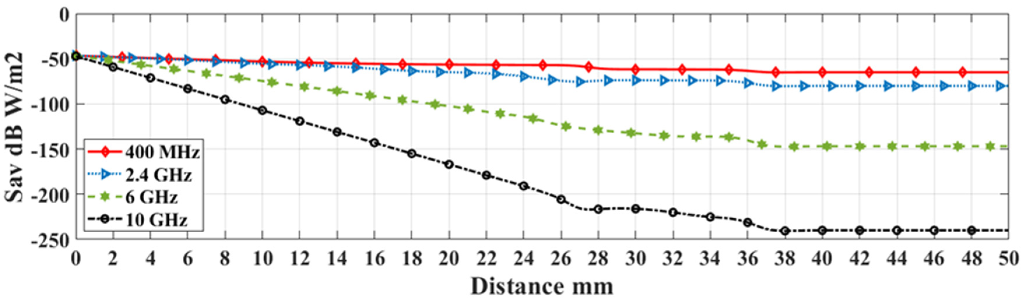
3.4. Operating Frequency and Biological Effect

Many parameters have major effects on the amount of absorbed energy in human tissues, such as the EM wave strength, operating frequency, and the tissue’s composition as its water and salt contents. At high frequencies, the absorption of the EM field by heat conversion at the tissue becomes stronger, which shortens the distance that the EM wave can penetrate into the body. However, the penetration depth also depends on the initial field strength. At the same operating frequency, the initial field strength must be increased to obtain a longer penetration into the body.
The dielectric properties of the tissue, such as permittivity and conductivity, are governed by the tissue structure and distribution of water molecules, ions, and other molecules. This influences the level of absorption of the field in different tissues. A higher conductivity, due to higher water or salt content, increases the absorption of the field within the tissue and thus the thermal effect. Hence, there are areas in the body with higher local heating and areas with lower heating compared to the surrounding tissues. Bone and fatty tissue, for example, are heated less than other tissues because of their low conductivity due to low water content. The depth of penetration is associated with the tissue-depending thermal effect. It is higher in fatty and bone tissues than in muscle tissues, which absorb the field to a greater extent. Thus, the field energy is converted into heat efficiently. Most of the loss occurs in the muscles and skin due to the largest conductivity and the thickness of the muscle [25]. For the electric field intensity E i (V/m) and conductivity σ i (S/m), the average power dissipation P i (W/m3) at a position (i) in the tissue is expressed as:
P i = E i 2 σ i 2   W / m 3
Figure 3 shows the penetration of the EM wave through a model composed of three consecutive layers of muscle, fat, and skin at the common operating frequencies of the MICS and SIM bands. The x-axis represents the distance travelled by the wave through the consecutive tissue layers. The value of the APD, along with the tissues, shows better penetration at lower frequencies. The electric and magnetic fields’ equations are taken from [26]. Power density values Sav at any position (i), along with the model in Equation (2), are calculated by MATLAB codes.
S av = 1 2   R e   ( E i   ×   H i * )
A universal radio frequency (RF) band of 401–406 MHz, for which the core band is 402–405 MHz, has been proposed for the medical implant communication systems (MICSs). The EM waves corresponding to this band have good penetration in the human body, a higher data rate, and a longer communication range [27,28]. Table 3 illustrates the dielectric properties of human tissues at 402 MHz [29].
The specific absorption rate (SAR) quantifies the EM radiation absorption by tissues and represents the amount of energy or power absorption per unit mass of biological tissue. For a tissue density ρ i (kg/m3), conductivity σ i and dissipated power density P i (W/m3), the average local SAR (W/kg) at position (i) is given by:
SAR = P i ρ i = E i 2 σ i 2 ρ i   W / kg
Figure 4 presents the variation in the SAR in the different tissues of the humerus at 400 MHz, 6 GHz, and 10 GHz. At the beginning of the tissue, the value of the SAR is high at the higher frequencies due to the electric field absorption and heat conversion. The following layers experience a low value of SAR at higher frequencies because most of the EM wave is already absorbed. As the penetration of the 400 MHz waves through the tissue is higher than the other frequencies, it shows a clear behavior of SAR along with the tissue. The curve shows a lower value of SAR in bone and fat tissue than in muscle and skin due to variations in the electrical properties and composition of the tissue. At high frequencies, it is required to decrease the strength of the initial electric field which has additional drawbacks on the signal penetration through the human tissue. The reason behind that is to save the increase in the SAR at the beginning of the model to safe levels. This reduction in penetration may block communication with the monitoring device outside the body. So, this distribution of SAR values gives an advantage of 400 MHz over the other studied frequencies. The different densities of human upper arm tissues are shown in Table 4.
The International Commission on Non-Ionizing Radiation Protection (ICNIRP) and the IEEE C95.1-2019 standards set the SAR limit to 2 W/kg for the average of over 10 g of tissue [31].

4. Simulation and Discussion

The model described in Section 3.1 is simulated by CST. Due to the morphology of the human upper arm, there is limited space for the implanted antenna. We select a half-wave dipole antenna due to its simplicity and suitability to be implanted in the cylindrical model. In the half-wave dipole antenna, two conductors are installed in line with a small gap left between them. The voltage is attached to the center of both conductors, and the length of the dipole ought to be half of the wavelength [32].
The voltage and current levels vary along the length of the radiating section of the antenna. This occurs because the standing waves are set up along the length of the radiating element. The current then reaches the maximum level and the voltage reaches the minimum level at a length equal to an electrical quarter wavelength from the ends. This process takes place in the center as it is a half-wave dipole. As excitation to the antenna is delivered at the center, it can be said that feeding to the dipole is presented at the quarter wavelength point. It is a linear current whose amplitude varies as one-half of a sine wave with a maximum at the center of the antenna. The energy from the driving current provides the energy radiated as radio waves.
The antenna is implanted parallel to the bone axis between the bone and the muscle tissue. The upper arm is considered to be concentric with the z-axis, whereas the transverse fracture is modeled by a circular layer at a right angle to it. Two cases of oblique fracture are represented by elliptical layers that make 30° and 60° with the y-axis. Figure 5 shows the bone shaft with transverse fracture and oblique fracture layer with angle θ .
For biocompatibility with human tissue, the radiator part and the substrate of FR-4 (lossy) of εr =4.3 and a loss tangent of 0.025 were coated by an ultrathin sheet of silicon. Figure 6 shows a cross-sectional elevation, while the plan of the antenna and the dimensions within the human body are illustrated in Table 5.
When simulating the antenna in air, the wavelength is 745.75 mm, and the first resonance of the dipole is expected to occur at 0.47 wavelength [17]. For a trace width of 1 mm, a minimum return loss of −33.5 dB is obtained at a length of 350.5 mm. The simulation experiences a total efficiency of 0.9873 and a realized gain of 2.145 dB in air. The power pattern of the antenna in the air shows a symmetric pattern around the radiator as in Figure 7a.
According to the electrical properties of the human tissues, the wavelength of the 402 MHz frequency in the muscle is 312.09 mm, and in the bone is 206.02 mm. As the antenna in the proposed technique is implanted in the bone to the muscle interface, it resonates at a length of 111 mm and a trace width of 1 mm. The power pattern of the antenna within human tissue is shown in Figure 7b. The challenges of such an implant are low radiation efficiency, strong coupling to the surrounding lossy tissues, and the dispersive tissue and antenna impedance detuning. The antenna within the human tissue provides a total efficiency of 0.0247 and realized gain of −13.4 dB, as demonstrated in Figure 7c, while Figure 7d shows the variation in the realized gain and total efficiency with the frequency band.
The result of the maximum simulated SAR value of the antenna embedded in the human arm tissue is 1.62 W/kg, as shown in Figure 8, for the average input power of 20 mW. This value satisfies the IEEE C95 standard.
The simulation of S11, which provides information about the power reflected back from the antenna, shows −38.15 dB in the case of normal bone and −15.8 dB, −16.5 dB, and −15.5 dB for the transverse, 30° and 60° oblique fractures, respectively. Figure 9 shows the return loss in cases of normal and the studied types of upper arm fractures.
From the geometry of the 3D pattern shown in Figure 7b, we select to test the change in the transmitted APDs at two constant Φ at ±90°, in which the transmitted APD is at its greatest value. At these two positions, the difference between the transmitted APD in cases of a normal and fractured bone also experiences a considerable value. Figure 10 shows the electric field distribution and a comparison between the transmitted APD at a distance of 30 cm in the far-field of the antenna for the normal and fractured humerus. This observation is recorded at constant values ±90° of Φ angle at which the maximum transmitted power is obtained. The result of this comparison represents the healing status. The results for transverse fracture, 30° and 60° oblique fractures at the points of maximum transmission were considered.
Table 6 provides a comparative result of the transmitted APD in the normal and fractured humerus. The greater the difference between the transmitted APD outside the body in cases of normal bone and fractured bone, the better the monitoring of the bone healing status. The transmission at Φ = 90° for normal and fractured humerus’ is greater than that at Φ = −90°. This is due to the shorter distance that the radiation passes in the lossy tissue medium as this direction excludes propagation through the bone and transmission through the muscle, fat, and skin to the air outside the body. This shorter path saves 27.2% of the transmitted power density. The percentage reduction in transmission due to the fractures is comparable at two values ± 90° of Φ.

5. Measurement and Validation

In this paper, the front leg of a lifeless animal was chosen for carrying out the experimental measurements. It should be mentioned that the model used in the experiments is a fresh front leg of a cow and it was procured from a local butcher for normal consumption, so no animals were harmed specifically for this study. This model was selected to be close in composition to human arm tissues. However, there is a difference in the amount of blood between the non-living model and the human arm. The system shown in Figure 11 consists of a vector network analyzer NanoVNA-F V2, SMA cable of connecting the antenna and the VNA, 116 × 5 mm2 planar, and 120 mm wire half-wave dipole antennas, the animal model, medical splint, fixation plate, and a computer.
In surgical treatment of such fractures, first the surgeon cuts the skin and muscles to move the bone back into the normal position. Second, a metal rod, screws, and plates are attached to the bone to hold it. Finally, the surgeon closes the incision with stitches or staples, applies a bandage, and puts the limb in a cast or splint depending on the location and the type of fracture [33].
In this study, we performed the same surgical operation on the selected model with the aid of a specialist. The experiment is based on measuring the reflection coefficient of the implanted antenna in cases of normal and fractured bone.
Measurements were carried out in two phases. The first phase represents the model after bone healing completion. We opened the tissue at a length suitable to the dimension of the antenna and the depth was up to the bone. The antenna was implanted in the bone to muscle boundary. On the opposite side, the tissue was opened, and the plate was fixed. The opened tissue was then closed by surgical stitches. A medical splint was added to the model, and the reflection coefficient was measured. This step was repeated for both antennas.
In the second phase, the bone was obliquely broken, and measurements were taken. Figure 12 shows the measurements in cases of normal and fractured bone using both antennas.
It was easier to implement and adjust the wire antenna’s length to resonate at the operating frequency, while it was more difficult than the planar antenna to fix within the tissue.
The measurements showed good agreement compared to the simulation results. Figure 13 shows a comparison between the results of simulation and measurement for planar and wire antenna.
The simulated model was approximated as concentric cylinders of tissues around the humerus shaft, while the real model is not symmetric and there are three muscles, vanes, and blood suppliers around the bone shaft. In addition to the difference between the real and assumed model, the change in the thickness of tissues with different people, like adults, as in this model, and children, was expected to affect the experimental results. There was a deviation between the simulation and measurements. However, the difference between the normal and fractured bone was remarkable in both cases, which showed good monitoring.
The experimental measurements showed good matching with the simulation for both topologies of the implanted antenna.

6. Conclusions

In this study, an application for the post-surgery monitoring of humerus fracture healing was proposed. Different types of fractures were considered in monitoring. The monitoring depended on measuring the difference between the far-field APD of an implanted planar and the wire half-wave dipole antennas in cases of a normal and fractured humerus. The measuring also depended on selecting the best position for recording this difference. The return loss of the implanted antenna was also taken into consideration. Two different positions of observation were taken into account according to the simulation of the far-field power pattern of the implanted antenna. The maximum difference in APDs was observed at Φ = 90° and Ɵ = 91°. The results show a reduction of 11.57% to 15.45% of the transmitted APD when the humerus was broken. This considerable difference for all of the studied fracture types provides information about bone healing. The return loss showed a remarkable difference between the normal and fractured humerus cases. The specific absorption rate was considered in the antenna design to guarantee its safety for human tissues. The technique was verified experimentally using a lifeless animal model, and the results showed good matching with the simulation.

Author Contributions

Conceptualization, W.Z. and R.U.; methodology, W.Z. and R.U.; software, W.Z.; experiments and measurements, W.Z.; validation, W.Z. and R.U.; writing original draft preparation, W.Z.; writing review and editing, W.Z. and R.U.; supervision, R.U. All authors have read and agreed to the published version of the manuscript.

Funding

This research received no external funding.

Institutional Review Board Statement

Ethical review and approval were waived for this study, due to the study was conducted following the ethical guidelines of Eastern Mediterranean University https://bayek.emu.edu.tr/en/regulations, which were announced on 12 May 2022.

Informed Consent Statement

Not applicable.

Data Availability Statement

Data sharing is not applicable to this article as no datasets were generated or analyzed during the current study.

Conflicts of Interest

The authors declare no conflict of interest.

References

  1. Malasinghe, L.P.; Ramzan, N.; Dahal, K. Remote patient monitoring: Acomprehensive study. J. Ambient. Intell. Humaniz. Comput. 2019, 10, 57–76. [Google Scholar] [CrossRef] [Green Version]
  2. Kasban, H.; El-Bendary, M.A.M.; Salama, D.H. A comparative study of Medical imaging techniques. Int. J. Inf. Sci. Intell. Syst. 2015, 4, 37–58. [Google Scholar]
  3. Li, Y.; Duan, W.; Yang, L.; Zhao, X. Study on the Electromagnetic field distribution of an Implantable Antenna for Intelligence Health Monitoring System. IEEE Access 2019, 7, 28749–28756. [Google Scholar] [CrossRef]
  4. Damaj, A.W.; El Misilmani, H.M.; Abou Chahine, S. Implantable Antenna for Biomedical Applications: An Overview on Alternative Antenna Design Methods and Challenges. In Proceedings of the 2018 International Conference on High Performance Computing and Simulation, Orleans, France, 16–20 July 2018; pp. 31–37. [Google Scholar]
  5. Skrivervik, A.K. Implantable Antennas: The challenge of efficiency. In Proceedings of the 2013 7th European Conference on Antenna and Propagation EUCAP, Gothenburg, Sweden, 8–12 April 2013; pp. 3627–3631. [Google Scholar]
  6. Skrivervik, A.K.; Merli, F. Design Strategies for Implantable Antennas. In Proceedings of the 2011 Loughborough Antenna and Propagation Conference, Loughborough, UK, 4–15 November 2011; pp. 1–5. [Google Scholar]
  7. Liu, C.; Guo, Y.X.; Xiao, S. A Review of Implantable Antennas for Wireless Biomedical Devices. 2016. Available online: https://www.semanticscholar.org/paper/A-Review-of-Implantable-Antennas-for-Wireless-Liu-Guo/bc57aa622cf5902e61bb1893fff563554f71ccc6 (accessed on 1 March 2023).
  8. Shah, S.A.A.; Yoo, H. Scalp-Implantable Antenna systems for Intracranial pressure Monitoring. IEEE Trans. Antenna Propag. 2016, 66, 2170–2173. [Google Scholar] [CrossRef]
  9. Lucisano, J.Y.; Routh, T.L.; Lin, J.T.; Gough, D.A. Glucose Monitoring in Individuals with Diabetes Using a Long-Term Implanted Sensor/Telemetry System and Model. IEEE Trans. Biomed. Eng. 2017, 64, 1982–1993. [Google Scholar] [CrossRef] [PubMed] [Green Version]
  10. Sinha, S.; Niloy, T.R.; Hasan, R.R.; Rahman, M.A. In-body antenna for Monitoring and Controlling Pacemaker. Adv. Sci. Technol. Eng. Syst. J. 2020, 5, 74–79. [Google Scholar] [CrossRef] [Green Version]
  11. Fallahpour, M.; Zoughi, R. Antenna miniaturization techniques. A review of topology and material based methods. IEEE Antennas Propag. Mag. 2018, 60, 38–50. [Google Scholar] [CrossRef]
  12. Krzysztofik, W.J.; Cao, T.N. Metamaterials in Application to improve antenna parameters. Metamater. Metasurfaces 2018, 12, 63–85. [Google Scholar] [CrossRef] [Green Version]
  13. Kumar, P.; Ali, T.; Pai, M.M. Electromagnetic Metamaterials: A new paradigm of Antenna design. IEEE Access 2021, 9, 18722–18751. [Google Scholar] [CrossRef]
  14. Crean, T.E. Nallamothu SV Distal Humerus Fractures. Bookshelf ID: NBK531474. Medline. 2019. Available online: https://pubmed.ncbi.nlm.nih.gov/30285369/ (accessed on 1 March 2021).
  15. Launonen, A.P.; Sumrein, B.O.; Reito, A.; Lepola, V.; Paloneva, J.; Jonsson, K.B.; Wolf, O.; Strom, P.; Berg, H.E.; Felländer-Tsai, L.; et al. Operative versus non-operative treatment of proximal humeral fractures: A multicentered normalized controlled trial. PLoS Med. 2019. [Google Scholar] [CrossRef] [Green Version]
  16. Zeinelabedeen, W.; Uyguroglu, R. Characterization of human body channel for oblique incident case of plane wave in the 0.1–10 GHz frequency band for special health care monitoring application. In Proceedings of the SIU 2020, the 28th IEEE Conference on Signal Processing and Communications Applications, Gaziantep, Turkey, 5–7 October 2020; pp. 1–4. [Google Scholar]
  17. Bocan, K.N.; Mickle, M.H.; Sejdić, E. Tissue Variability and Antennas for Power Transfer to wireless implantable Medical Devices. IEEE J. Transl. Eng. Health Med. 2017, 5, 1–11. [Google Scholar] [CrossRef]
  18. Jung, Y.H.; Qiu, Y.; Lee, S.; Shih, T.Y.; Xu, Y.; Xu, R.; Lee, J.; Schendel, A.A.; Lin, W.; Williams, J.C.; et al. A Compact Parylene-Coated Wireless Flexible Antenna For Implantable Electronics. IEEE Antennas Wirel. Propag. Lett. 2016, 5, 1382–1385. [Google Scholar] [CrossRef]
  19. Patil, K.S.; Rufus, E. A review on antennas for biomedical implants used for IoT based health care. Sens. Rev. 2020, 40, 273–280. [Google Scholar] [CrossRef]
  20. Merli, F.; Bolomey, L.; Zurcher, J.F.; Corradini, G.; Meurville, E.; Skrivervik, A.K. Design, realization, and measurements of a miniature antenna for implantable wireless communication systems. IEEE Trans. Antennas Propag. 2011, 59, 3544–3555. [Google Scholar]
  21. Mahe, Y.; Chousseaud, A.; Brunet, M.; Froppier, B. New flexible medical compact antenna: Design and analysis. Int. J. Antenna Propag. 2012, 2012, 837230. [Google Scholar] [CrossRef] [Green Version]
  22. Psathas, K.A.; Kiourti, A.; Nikita, K.S. A novel conformal antenna for ingestible capsule endoscopy in the Med-Radio band. In Progress in Electromagnetic Research Symposium Proceeding; PIERS: Stockholm, Sweden, 2013; pp. 1899–1902. [Google Scholar]
  23. Xu, L.J.; Guo, Y.X.; Wu, W. Bandwidth enhancement of an implantable antenna. IEEE Antenna Wirel. Propag. Lett. 2014, 14, 1510–1513. [Google Scholar] [CrossRef]
  24. Alrawashdeh, R.S.; Huang, Y.; Kod, M.; Sajak, A.A.B. A broadband flexible loop antenna with complementary split ring resonator. IEEE Antennas Wirel. Propag. Lett. 2015, 14, 1506–1509. [Google Scholar] [CrossRef]
  25. Chen, Z.Y.; Gao, Y.M.; Du, M. Propagation characteristics of electromagnetic wave on multiple tissue interfaces in wireless deep implant communication. IET Microw. Antenna Propag. 2018, 12, 2034–2040. [Google Scholar] [CrossRef]
  26. Zeinelabedeen, W.; Uyguroglu, R. A study on health care monitoring of femoral shaft fracture healing by using implanted antenna for wireless in-toout body channel communication. J. Electromagn. Waves Appl. 2022, 36, 722–742. [Google Scholar] [CrossRef]
  27. Islam, M.N.; Yuce, M.R. Review of Medical Implant Communication System (MICS) Band and Network. ICT Express 2016, 2, 188–194. [Google Scholar] [CrossRef] [Green Version]
  28. Pflug, H.W.; Visser, H.J.; Kiyani, N.F.; Dolmans, G.; Philips, K.; Kanda, K.; Hamaminato, M.; Masui, S. Radio Channel Characterization for 400 MHz Implanted Devices. In Proceedings of the 2014 IEEE Wireless Communication and Networking Conference WCNC Track 1 (PHY and Fundamentals), Istanbul, Turkey, 6–9 April 2014; pp. 293–298. [Google Scholar]
  29. Hasgall, P.A.; Di Gennaro, F.; Baumgartner, C.; Neufeld, E.; Lloyd, B.; Gosselin, M.C.; Payne, D.; Klingenböck, A.; Kuster, N. IT’IS Database for Thermal and Electromagnetic Parameters of Biological Tissues. Version 4.0. 15 May 2018. Available online: https://itis.swiss/database (accessed on 14 March 2021). [CrossRef]
  30. Omar, A.A.; Bashayreh, Q.M.; Al-Shamali, A.M. Investigation of the effect of obliquely incident plane wave on a human head at 900 and 1800 MHZ. Int. J. RF Microw. Comput. Aided Eng. 2010, 20, 133–140. [Google Scholar] [CrossRef]
  31. C95.1-2019; IEEE Standard for Safety Levels with Respect to Human Exposure to Electric, Magnetic, and Electromagnetic Fields, 0 Hz to 300 GHz. The Institute of Electrical and Electronics Engineers: New York, NY, USA, 2019.
  32. Khan, A.Q.; Riaz, M.; Bilal, A. Various Types of Antennas with Respect to their Applications: A Review. Int. J. Multidiscip. Sci. Eng. 2016, 7, 1–8. [Google Scholar]
  33. Nunes, K. Repairing Major Bone Breaks with Open Reduction Internal Fixation Surgery, Medically Reviewed by William Morrison, M.D. 16 January 2019. Available online: https://www.healthline.com/health/orif-surgery (accessed on 10 October 2021).
Figure 1. (a) Upper arm fracture, (b) fixation plates, and (c) surgically treated arm.
Applsci 13 07786 g001
Figure 2. (a) Cross-section of the upper arm; (b) cylindrical model of the surgically treated fractured humerus.
Applsci 13 07786 g002aApplsci 13 07786 g002b
Figure 3. Penetration of EM wave along with three layers human tissue model at different frequencies.
Applsci 13 07786 g003
Figure 4. Variation in specific absorption rate along the tissues at different frequencies.
Applsci 13 07786 g004
Figure 5. Bone shaft with transverse and oblique fracture layers.
Applsci 13 07786 g005
Figure 6. Planar half-wave dipole antenna.
Applsci 13 07786 g006
Figure 7. Three-dimensional and planar far-field pattern of the antenna (a) in air and (b) in tissue. (c) Realized gain in tissue and (d) variation in realized gain and total efficiency with frequency.
Applsci 13 07786 g007aApplsci 13 07786 g007bApplsci 13 07786 g007c
Figure 8. Simulated SAR in tissue.
Applsci 13 07786 g008
Figure 9. S parameter for normal and fractured humerus.
Applsci 13 07786 g009
Figure 10. The electric field distribution; (a) variation in transmitted APD at (b) Φ =90° and (c) Φ = −90° for the normal humerus, transverse fractured humerus and 30° and 60° oblique fractured humerus.
Applsci 13 07786 g010aApplsci 13 07786 g010b
Figure 11. (a) The model, (b) antennas and fixation plate, (c) medical splint, (d) the fractured bone, and (e) the set.
Applsci 13 07786 g011
Figure 12. Measurements of return loss in cases of normal and fractured bone by using wire and planar half-wave dipole antennas.
Applsci 13 07786 g012aApplsci 13 07786 g012b
Figure 13. Comparison between measurements and simulation results in case of (a) wire antenna and (b) planar antenna.
Applsci 13 07786 g013
Table 1. Dimensions of the model and fixation plate.
Tissue ThicknessDimension in mm
Bone12.5
Muscle27.5
Fat8.5
Skin1.5
Length of model350
Fracture thickness2
Split thickness3
Fixation plate length100
Fixation plate width8
Fixation plate thickness3
Table 2. Biocompatible antennas.
ReferenceAntenna TypeOperating FrequencySize in mm3SubstrateGain
[18]Microstrip2.4 GHz482Polymide−18.8 dB
[20]Multilayer helical401–406 MHz301Rogers TMM10−28.8 dB
[21]Microstrip and meandered434 MHz119FR4−33 dB
[22]Microstrip402 MHz240Rogers RT/Duroid 5882−29.64 dB
[23]Asymmetric dipole fed402 MHz264Rogers 3010−37 dB
[24]Asymmetric dipole401–406 MHz75Polymide−25 dB
Table 3. Dielectric properties of human tissues at 402 MHz.
TissueRelative Permittivity εrConductivity σ s/m
Bone13.10.0917
Muscle5.710.797
Fat11.60.0808
Skin46.10.689
Blood64.21.35
Table 4. Density of humerus tissue [30].
TissueBoneMuscleFatSkin
ρ (kg/m3)184010609201010
Table 5. Antenna dimensions within human tissue.
Antenna ParameterDimension in mmAntenna ParameterDimension in mm
Radiator length111Substrate length116
Radiator width1Substrate width5
Radiator thickness0.035Substrate thickness0.5
Gap1Coating thickness0.1
Trace width1
Table 6. Comparison between transmitted APD for the normal and fractured humerus.
Humerus Status/Monitoring ParameterNormalTransverse Fractured30° Oblique Fractured60° Oblique Fractured
Return loss dB−38.15−15.8−16.5−15.5
Φ = 90°Transmitted power density µW/m216021417.614171354.4
% Reduction 11.57%11.54%15.45%
Φ = −90°Transmitted power density µW/m211661027.51026.7982.4
% Reduction 11.87%11.95%15.75%
Disclaimer/Publisher’s Note: The statements, opinions and data contained in all publications are solely those of the individual author(s) and contributor(s) and not of MDPI and/or the editor(s). MDPI and/or the editor(s) disclaim responsibility for any injury to people or property resulting from any ideas, methods, instructions or products referred to in the content.

