Article

Innovative Implantable Left Ventricular Assist Device—Performance under Various Resistances and Operating Frequency Conditions

1
Faculty of Mechanical Engineering and Ship Technology, Gdansk University of Technology, 80-233 Gdansk, Poland
2
Medarch Ltd., ul. Piaskowa 3, 83-110 Tczew, Poland
3
Department of Cardiac and Vascular Surgery, Medical University of Gdansk, 80-210 Gdansk, Poland
*
Author to whom correspondence should be addressed.
Appl. Sci. 2023, 13(13), 7785; https://doi.org/10.3390/app13137785
Submission received: 31 May 2023 / Revised: 24 June 2023 / Accepted: 28 June 2023 / Published: 30 June 2023
(This article belongs to the Section Biomedical Engineering)

Abstract

:
This paper presents the operation of an innovative left ventricular assist device under various resistances and operating frequencies. The operating principle of the device is based on pulsatile blood flow, which is forced by a suction–discharge device pumping helium into a set of intra-cardiac balloons. In this way, the ejection fraction of the left ventricle is increased, and the mitral valve is additionally occluded. What is more, the suction–discharge device is part of a portable pumping system that is synchronized with the heart cycle by monitoring the ECG signal. The device is implanted in a minimally invasive manner and is suitable for patients with stage D heart failure accompanied with residual mitral regurgitation. A model of the heart was built on the basis of a realistically reconstructed heart geometry and is part of an overall test stand that allows for realistic conditions in the heart of patients with end-stage heart failure to be reproduced. In the following sections, example measurements of the pressures in the heart chambers and balloons are shown, demonstrating that the device works correctly at least on a laboratory scale. The entire device, including the pumping system, is portable and powered by a set of lithium-ion batteries. From the measurements, it was observed, for example, that the flow rate varies with the frequency of the portable external balloon pumping system, up to 2.5 kg/min for 100 cycles/min at low flow resistance. As the flow resistance of the hydraulic system increases, the pressure in the heart chamber and aorta increases while the flow rate decreases.

1. Introduction

Heart failure is a constantly increasing health problem (e.g., 6.5 million people in the U.S. alone [1]) that is associated with high morbidity and mortality. Despite advances in medicine and surgical treatment, it is estimated that more than 40% of patients diagnosed with heart failure will die within five years [1,2,3,4]. Importantly, heart transplantation is considered the best treatment option in patients with advanced heart failure [5]. However, transplantation raises some difficulties, which are related to the lack of donors (e.g., 5500 in 2020 [6]). Further problems are the high costs (e.g., estimated USD 69.8 billion in 2030 [7]) and the large number of patients waiting for heart transplantation [8,9,10,11]. Additional problems include organ rejection and mortality rates [12], where it is estimated that the one-year survival rate is around 50% [13] for stage D heart failure. It should also be mentioned that stage D refers to patients with end-stage heart failure in the ABCD classification according to the American College of Cardiology [14].
If, for the above reasons, heart transplantation is not possible and other conservative treatments are unsuccessful to prevent further deterioration, mechanical circulatory support in the form of artificial blood pumps should be considered. Such devices in the form of left ventricular assist devices (LVADs) are used for both short-term and destination therapy. Moreover, LVAD is considered to be an effective therapeutic approach as a bridge to heart transplantation [15,16] even for patients with stage D (end-stage) heart failure. It is important that LVADs are also being used for destination therapy [17]. Among the many well-known solutions are, for example, intra-aortic balloon pumps, IMPELLA® [18], VA ECMO (e.g., [19,20]), POLVAD [21], Levitronix [22], CentriMag™ [23], TandemHeart™ [24], HeartMate 3™ [23], and HeartWare™ [25]. However, it should be noted that the devices currently available are used for temporary support of the ailing heart. This means that they are intended for patients during hospitalization and not for outpatient applications. Exceptions include HeartMate 3™ and HeartWare™, which allow patients to return home as long as close monitoring and batteries are not an issue.
Artificial blood pumps have been steadily developed over the past few decades, beginning in the 1960s, replacing cardiopulmonary bypass circuits [26]. This has led to increased survival rates for patients with advanced heart failure [27]. For instance, patients receiving HeartMate 2™ demonstrated an 85% survival rate at one year [28]. In general, we can distinguish two main types of LVAD: pulsatile and continuous flow devices. Until 2009, the former pumps were common, whereas since 2010, the latter devices have been used almost exclusively [29,30,31]. Furthermore, the first pulsatile pumps mimicked the cyclic action of the heart by means of artificial heart valves and diaphragms, resulting in their large size and weight, as well as noise. On the other hand, continuous flow devices are smaller, less noisy, and permit patient mobility. These pumps can be divided into axial [32,33] and centrifugal, where axial pumps are much smaller. In order to achieve the required pressure increments, axial pumps require significant angular velocities [34], which leads to unfavorable phenomena, i.e., thrombosis (blood clot formation at the blood–pump contact surface) [2,35] and hemolysis [36,37] phenomena. What is more, thrombosis may occur in any component of the pump and may lead, for instance, to higher power consumption. Importantly, most currently available pumps take advantage of a continuous blood flow mechanism, i.e., providing constant pressure, which contributes to arrhythmias in the heart [38,39].
A major disadvantage of current devices is the highly invasive surgery needed during implantation, such as median sternotomy or pericardiotomy, which have an adverse effect on patients with end-stage heart failure. Implantation of available circulatory support devices often results in elevated pulmonary pressure, worse ventricular function, and sometimes higher mortality [40,41,42], hence the need for a new left ventricular assist device that would require minimally invasive implantation with minor thoracic trauma that does not interfere with the breathing process. Moreover, owing to minimally invasive implantation, it is possible to significantly reduce hospitalization time. This is particularly important for patients with end-stage heart failure associated with mitral regurgitation and pulmonary hypertension, primarily when patients are resistant to pharmacological treatment or cannot undergo extensive cardiac surgery because of medical reasons. For patients with stage D heart failure, mechanical assistive devices are the best and safest solution strategy [4,43,44].
This paper investigates the performance of an innovative implantable left ventricular assist device, first introduced in [45,46], under various operating conditions, whose operating principle is based on pulsatile blood flow. The cardiac pulse is synchronized with the heart cycle by means of signals read from ECG measurements. This overcomes existing problems that are typical of axial pumps for circulatory support. Furthermore, the device is suitable for use in patients with stage D heart failure accompanied by residual mitral regurgitation and thus pulmonary hypertension and right ventricular dysfunction.

2. Implantable Left Ventricular Assist Device

A schematic of the device, which was first proposed in [45,46], for supporting the left ventricle is shown in Figure 1. The design consists of a set of two flexible balloons, with the larger ventricular balloon (2) placed in the left ventricle (5), and the smaller valve balloon (1) located in the mitral valve (3). Both balloons form expanding and contracting working chambers and can be adjusted to match the size of the individual heart chambers. Between the balloons, there is a narrowing (9) that separates the two working chambers. Inside the balloons is a pneumatic line (7) that supplies gas to both balloons by means of a suction–discharge device. Various designs of this line are possible, which can consist of two separate lines to supply each balloon separately or one common line [45]. This study used a pneumatic line in the form of a single line to supply both balloons. Importantly, this line has one outlet located at the top of the line in the valve balloon area and four smaller orifices in the ventricular balloon area, which are located under the narrowing (9). The position, number, and size of the orifices will ensure that the balloons work properly, ensuring appropriately synchronized inflation and deflation of the balloons. The correct choice of pneumatic line parameters resulted from experimental work, where a number of different solutions and their impact on balloon operation were tested. Importantly, a single pneumatic line does not require additional synchronization with the suction–discharge device control system, making the whole system simpler and more reliable.
The most important principle of the device is that the expansion and contraction of the balloons is synchronized with normal heart function. This means that during the systolic phase of the heart, the ventricular and valve balloons are inflated with inert gas (helium), resulting in an increase in stroke volume into the aorta (4) via the aortic valve (8). In addition, the valve balloon occludes or completely replaces the mitral valve. In contrast, during the diastolic phase of the heart, both balloons are deflated, which, among other things, allows blood to flow from the atrium (6) into the left ventricle (5).
A suction–discharge (Section 3.2), is used to transfer gas to the balloon set. The purpose of this device is to cyclically increase and reduce the volume of the balloons so that, during the systolic phase, the valve balloon is inflated first (mitral valve occlusion) and then the ventricular balloon (increase in stroke volume). During the diastolic phase, both balloons are deflated. The operation of the suction–discharge device is controlled by a control system (ODROID computer, Section 3.2) which ensures synchronization in line with the cardiac cycle. Signals are read and recognized in real time from ECG (electrocardiogram) measurements. Moreover, the control device also allows the volume of gas in the ventricular balloon to be varied during each cycle, thus ensuring a precise degree of circulatory support. This makes it possible to adjust cardiac output by changing the stroke volume. In addition, the control device allows for continuous monitoring of key cardiac and device parameters.
The operating principle of the device is shown in Figure 1. In the first stage of the cycle (start of diastole), the valve and ventricular balloons are deflated. The mitral valve is open, and the aortic valve is closed, causing blood to flow from the atrium into the left ventricle. In the second stage (end of diastole), the valve balloon is inflated with gas (helium), which causes the mitral valve to close and stops the inflow of blood from the atrium, ending the diastolic cycle. In the third stage (start of systole), the ventricular balloon is inflated, and the valve balloon is closed throughout. Inflation of the valve balloon causes the aortic valve to open and eject blood into the aorta. In stage four (end of systole), the ventricular balloon is inflated to its maximum extent. Gas is sucked out of the valve balloon, causing the mitral valve to open. The process of sucking gas out of the ventricular balloon begins, ending the systole cycle.
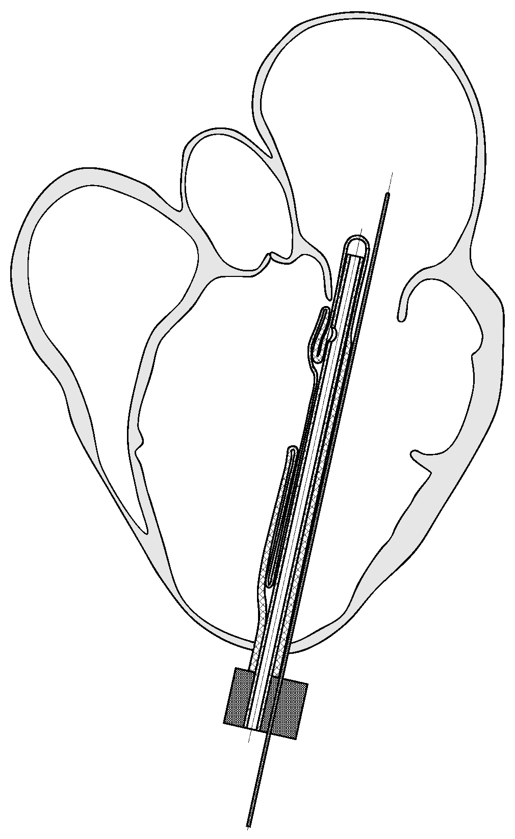
The design of the device permits it to be implanted into the heart chamber in a folded state (with deflated balloons), as shown in Figure 2. After implantation, the balloon assembly takes the correct shape, matching the shape of the left ventricle at the implantation site. This makes transcatheter implantation of the device possible, which does not require extensive surgical intervention and is therefore possible even for frail patients for whom classical surgery is not feasible. Additionally, if the device needs to be removed (e.g., when the function of the left ventricle improves), it can be folded and evacuated by the transcatheter procedure without burdening the patient.

3. Methods

3.1. Geometry Reconstruction

Geometry reconstruction consisted of creating models in the end-systolic and end-diastolic phases occurring in a patient with mitral valve regurgitation. The geometric data of the hearts came from imaging studies performed on patients who were involved in ongoing research projects at the Medical University of Gdansk. Patients consented, and approval was obtained from the Bioethics Committee. The cardiac CAD models were developed from selected CTA (computed tomography angiography) data of three patients with varying degrees of chronic post-myocardial infarction heart failure associated with mitral valve regurgitation with different LVEF (left ventricle ejection fraction), i.e., the percentage of blood ejected from the heart with each contraction:
  • LVEF 40%—a heart muscle of very small size. It was verified that the developed ventricular balloon would cooperate in the left ventricle of this heart;
  • LVEF 30%—small sized myocardium, which was the basis for the development of the ventricular balloon shape;
  • LVEF 17%—heart muscle of very large size. It was verified that the developed balloon would cooperate in the left ventricle of this heart.
It should be noted that normal LVEF takes values greater than 50%. This means that the latter two geometries can be classified as cases with chronically low ejection fraction (less than 30%).
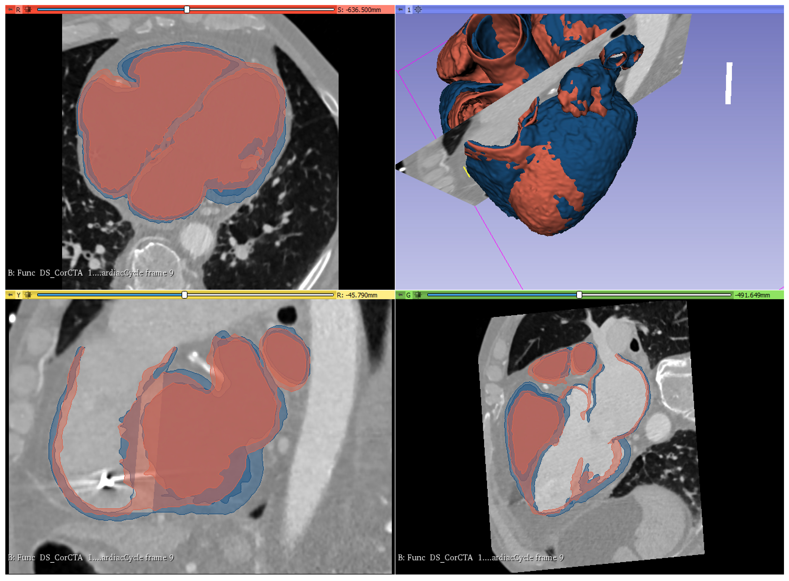
CTA imaging of the moving heart (in 10 frames) at a resolution of 0.4238 × 0.4238 × 1 mm was used to perform the segmentation (extracting the shape of the heart). From these data, images of the heart in the diastolic and systolic states were extracted in 3D Slicer [47]. Standard procedures in 3D Slicer were used for initial segmentation, followed by manual shape correction on approximately 1000 tomographic sections.
Figure 3 shows the combined image of the heart muscle shape in a single 3D image, in the systolic and diastolic states (red corresponds to the systolic phase and blue to the diastolic phase). The heart models in the systolic and diastolic states were then exported to STL format. Furthermore, these models, after reducing the number of nodes to around 60,000, were used for further CAD processing.
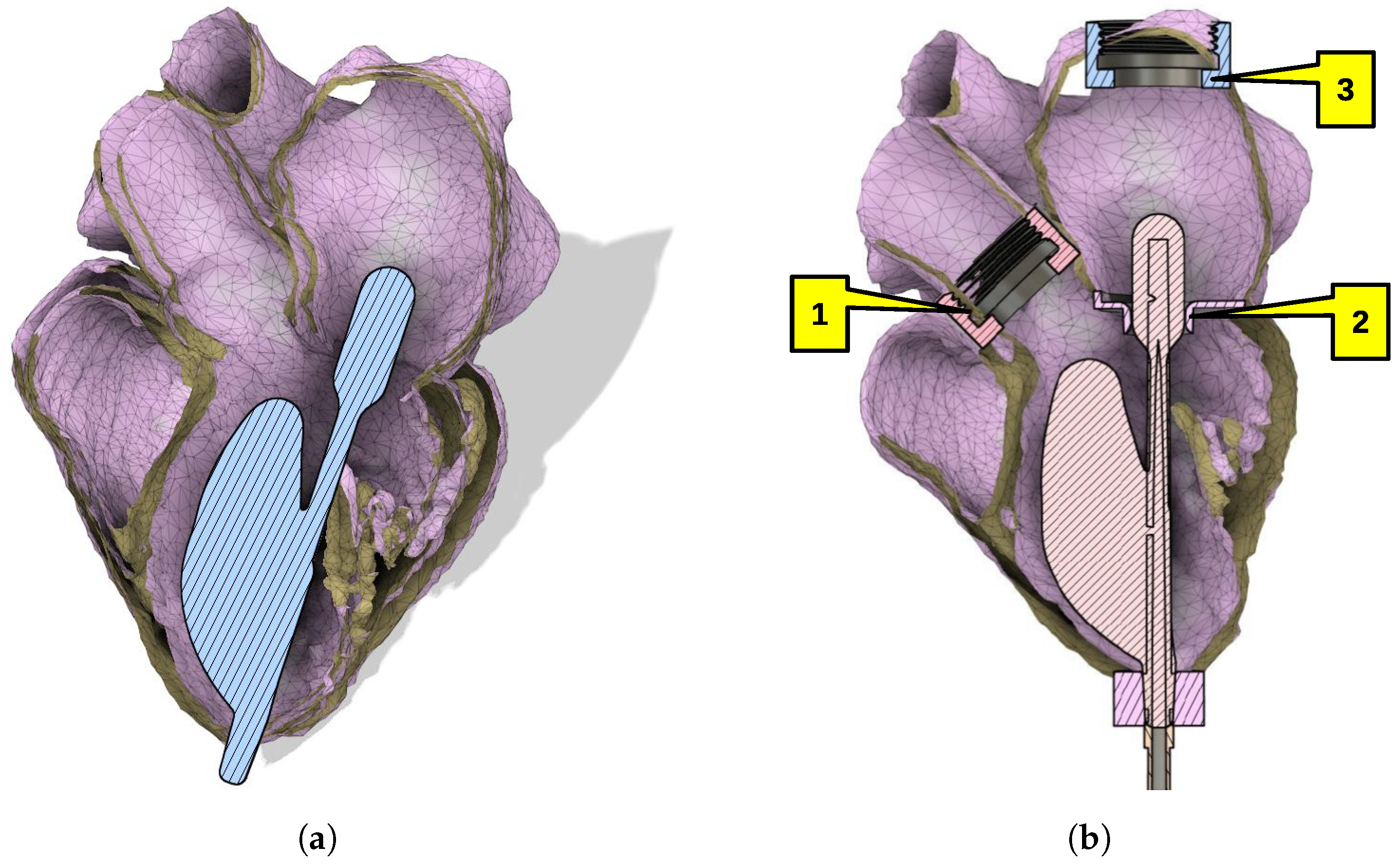
Figure 4a shows the initial design of the balloon set, including the pneumatic supply line against the background of the reconstructed heart model. Three superimposed heart models of three patients considered in systole were the basis of the ventricular balloon design.
Because an elastic heart model was used in the laboratory studies, a mechanical artificial valve (1) (see Figure 4b) was utilized in order to replace the aortic valve. The mitral valve with regurgitation was replaced by a cylindrical orifice (2), and the pulmonary arteries were reduced to a single conduit to the atrium (3). Further details on the construction of the heart model are given in [46].

3.2. Experimental Stand

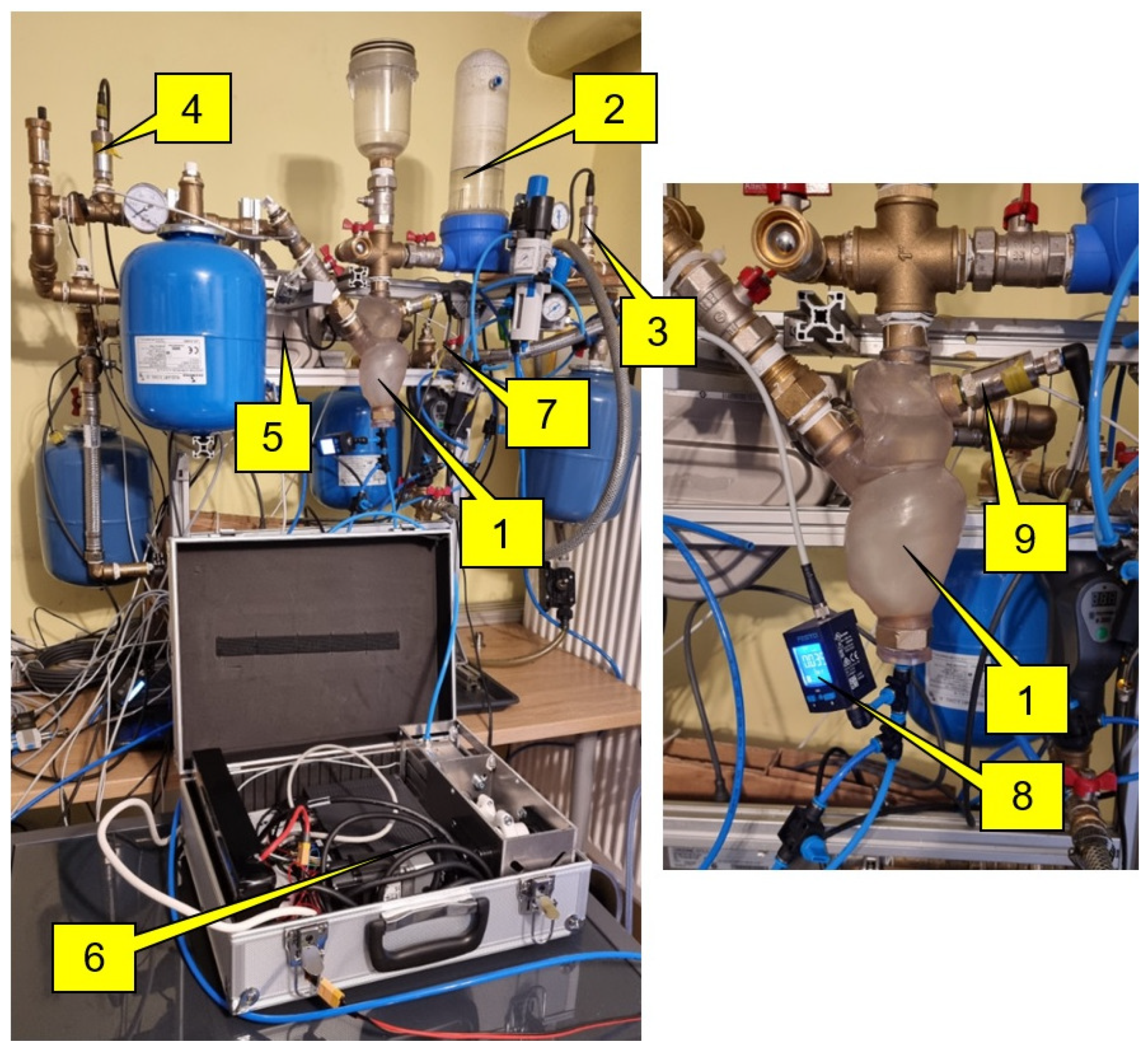
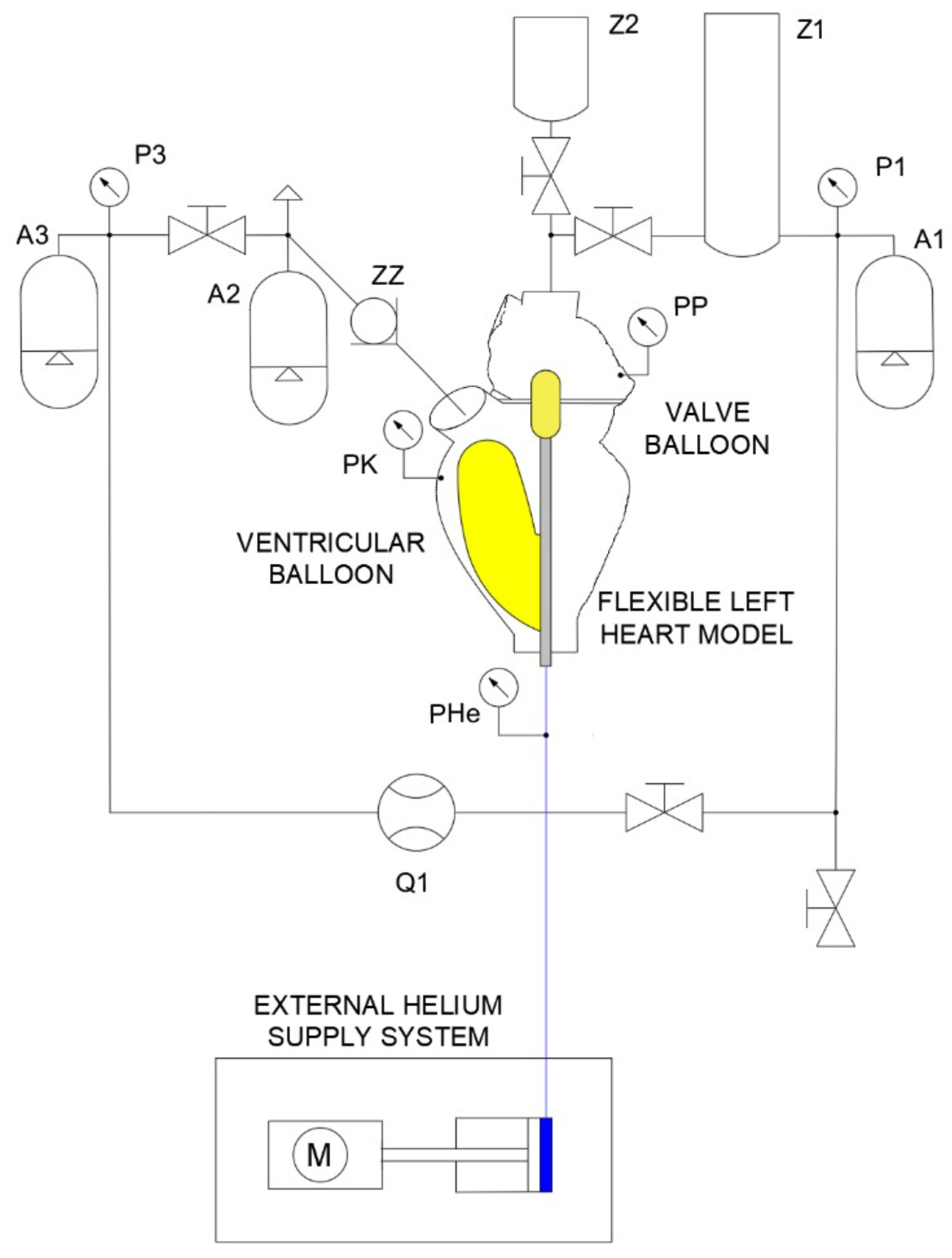
Figure 5 shows a fluid pumping test stand in a model system with an artificial heart using ventricular and valve balloons. The valve balloon is used to close the regurgitant valve opening between the atrium and left ventricle, and the ventricular balloon ensures that blood is pumped from the pulmonary veins into the aorta.
The balloon assembly was mounted in the flexible heart model (1) shown in Figure 5. This balloon assembly was supplied with helium from a portable external system (Figure 5). Before testing the system with the flexible heart model, the balloons were inflated with helium to an appropriate value, e.g., 75 mm Hg. During this operation, the piston rod of the compressor cylinder was retracted to its maximum.
Several pressure sensors (High Precision Transmitter ATM.1ST STS Sensor Technik Sirnach), a gas pressure sensor (SPAU-B2R-H- G18FD-L-PNLK-PNVBA-M8U from Festo), and a liquid flow meter (Krohne Optibatch 4011 C) were placed in the hydraulic system. The Optibatch 4011 C flow meter measures not only the mass flow rate of the liquid but also the density of the liquid and the temperature of the flowing liquid.
The diagram of the hydraulic system (Figure 6) shows the main and basic measuring and installation components. This measurement system allows fluid pressure to be measured at several locations. The fluid pressure was then measured in the pulmonary veins in front of the heart model (pressure sensor P1), the aorta (pressure sensor P3), the atrium (pressure sensor PP), and the left ventricle (pressure sensor PK). Further, the pressure of the gas (helium) in the pneumatic system close to the ventricular and valve balloons was measured by means of the pressure sensor PHe.
The external system supplying the helium balloon set consisted, among other things, of a servo-driven reciprocating compressor (1) with a crank mechanism (Figure 7). In order to increase the rigidity of the structure and to dissipate heat from the servo motor, the compressor body was made of aluminium alloy. An ODROID computer (4) via a Mitsubishi servo amplifier (3) controlled the compressor drive operation. A Mitsubishi 100 W servo motor (2) with a 10:1 planetary gear ratio was used to drive the device. Further, the servo motor was attached to the aluminium body through a plate made using FDM printing technology from carbon fiber-reinforced nylon to ensure high mechanical strength, rigidity, and resistance to high temperatures. The driven element was a Festo actuator with a piston diameter of 50 mm. The rotary motion of the servo motor shaft was converted into reciprocating motion by means of a crank mechanism, the components of which were made using 3D SLA printing. The crankshaft and connecting rod were supported by ball bearings.
Importantly, the unit has built-in battery power (5). A 12 V lithium–ion battery pack was used. The external gas power supply system (Figure 7) has a set of four independent 3s2p 12 V batteries connected in parallel. In order to reduce the weight of the external system, the number of batteries can be reduced. However, this will reduce the independent operation time of the system. Alternatively, the system can be connected to a 230 V domestic electrical installation. In addition, a 12/5 DC/DC converter was also used in order to provide 5 V voltage to power the ODROID computer and a 12/24 DC/DC converter to power the piston position sensor in the actuator to base the compressor system. Experimental tests were carried out in such a way that the Mitsubishi servo amplifier (3) in Figure 7 was powered from the domestic electrical installation, while the ODROID computer (4) in Figure 7 and the piston position sensor in the actuator for basing the compressor system were powered by inverters (12/5 DC/DC and 12/24 DC/DC) from the battery pack (5) in Figure 7.
The main features of the experimental design can be summarized in the following points:
  • Construction of a hydraulic system consisting of a flexible left heart, flow reservoir replacing the pulmonary veins, compensation vessels simulating the flexibility of the human circulatory system, flexible and rigid hydraulic lines, liquid and gas pressure sensors, liquid temperature sensors, liquid flow meter.
  • Placement and positioning of a balloon set in the left ventricle.
  • Filling the hydraulic system with liquid (artificial blood).
  • Before testing the system with the heart model, the balloon set was inflated with helium to an appropriate value (75 mm Hg). Furthermore, the piston rod of the compressor cylinder was retracted to its maximum.
  • Starting the external helium supply system from an ODROID computer.
  • Performing experimental tests under different operating frequencies and for different inflation and deflation times of the ventricular and valve balloons. The pressure in the hydraulic system was varied by increasing the flow resistance by means of a hydraulic valve setting, allowing for the simulation of different operating states through the fluid pressure in the system.
  • Performing tests for the most typical human heart frequencies, namely: 60, 80, and 100 cycles per minute.
  • Analysis of data from artificial blood pressure sensors located at several locations in the heart and hydraulic system installation, gas (helium) pressure, and artificial blood flow rate.

4. Results and Discussion

4.1. Visualization

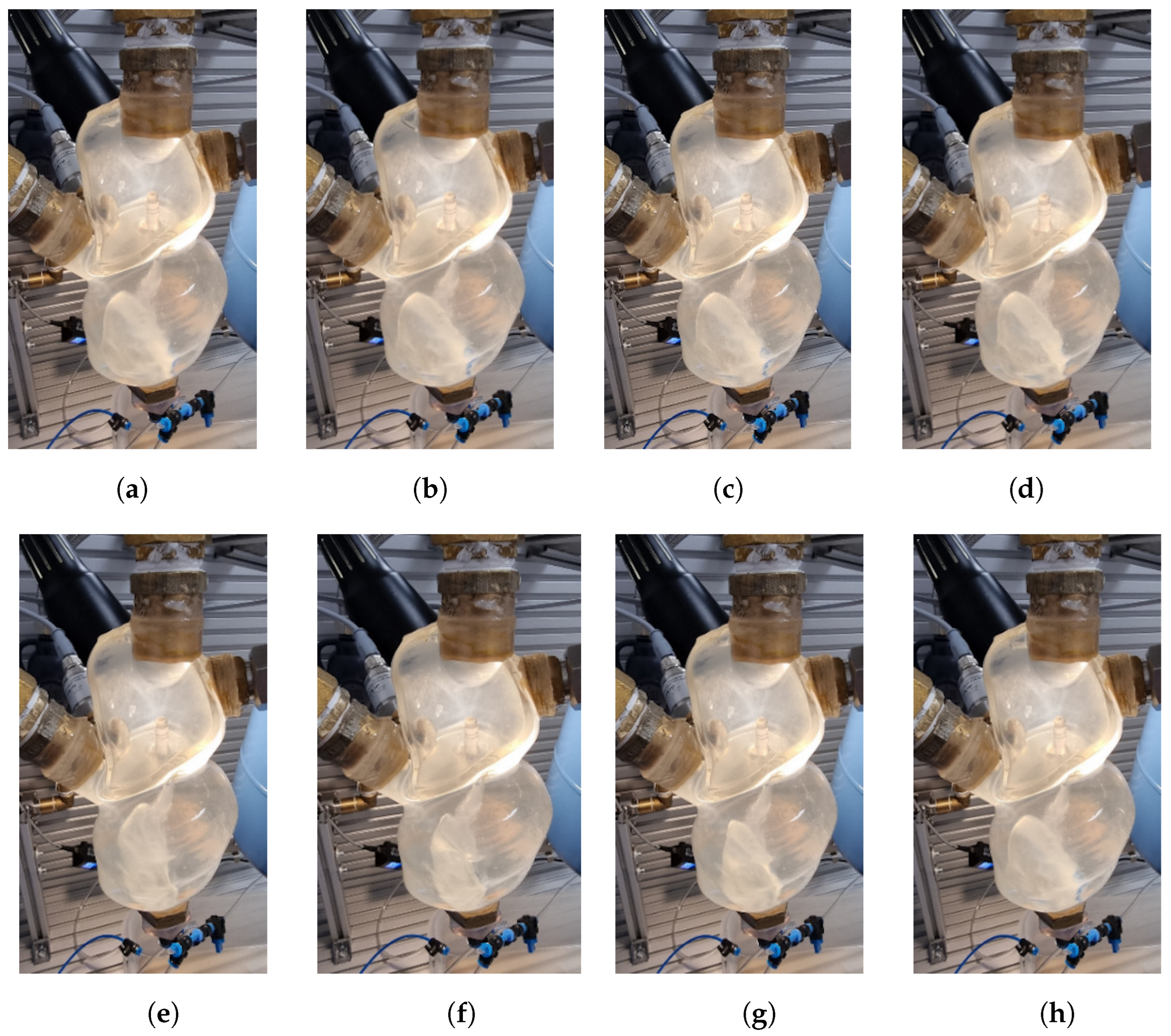
Figure 8 shows the operation of the ventricular and valve balloons mounted in the left heart model. Accurate observation of the ventricular and valve balloons is possible through the use of a heart model made of transparent material. The heart model was printed from resin on a 3D printer. In the lower part of the heart atrium, the valve balloon is visible and, in the ventricle, on the other hand, the operations of the ventricular balloon can be easily observed.
The individual images show the moments of unfolding (inflation) and folding (deflation of gas) of the balloons. First, the valve balloon collapses, as the gas (helium) is pumped out, as shown in Figure 8a–d. At this time, the valve opening (cylindrical orifice) between the atrium and left ventricle is open (Figure 8c). Further suction of the gas by the external gas supply system from the balloon set causes the ventricular balloon to collapse, reducing its volume. In place of the shrinking balloon, fluid flows from the atrium into the left ventricle as shown in Figure 8d–f. The suction of gas (helium) from the ventricular balloon is very clearly visible in Figure 8e,f. In the next phase, there is the process of filling the valve balloon (Figure 8g), closing the opening between the atrium and the ventricle. The ventricular balloon (Figure 8h) is then inflated with helium by the external gas supply system. Artificial blood is forced out of the ventricle via an open mechanical valve (ZZ, Figure 6) into the circulatory system.

4.2. Measurements

Among other things, the designed test stand permitted a number of fluid pumping tests to be carried out in a model system with an artificial heart using ventricular and valve balloons. The pressure in the hydraulic system was varied by increasing the flow resistance using the hydraulic valve setting, which enabled the simulation of different operating states of the circulatory system through the fluid (blood) pressure in the system.
Tests were carried out with two hydraulic valve settings (valve (7) in Figure 5):
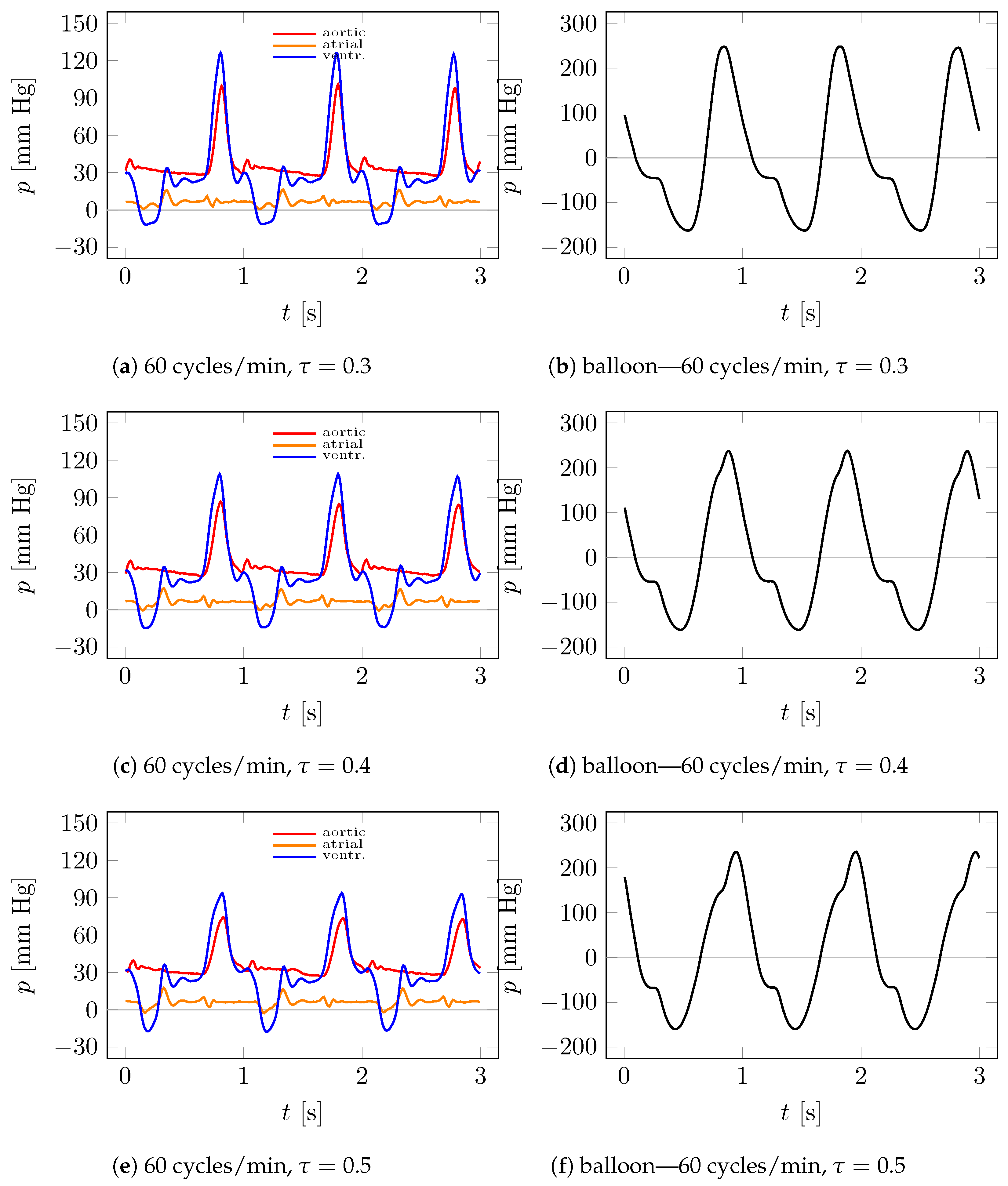
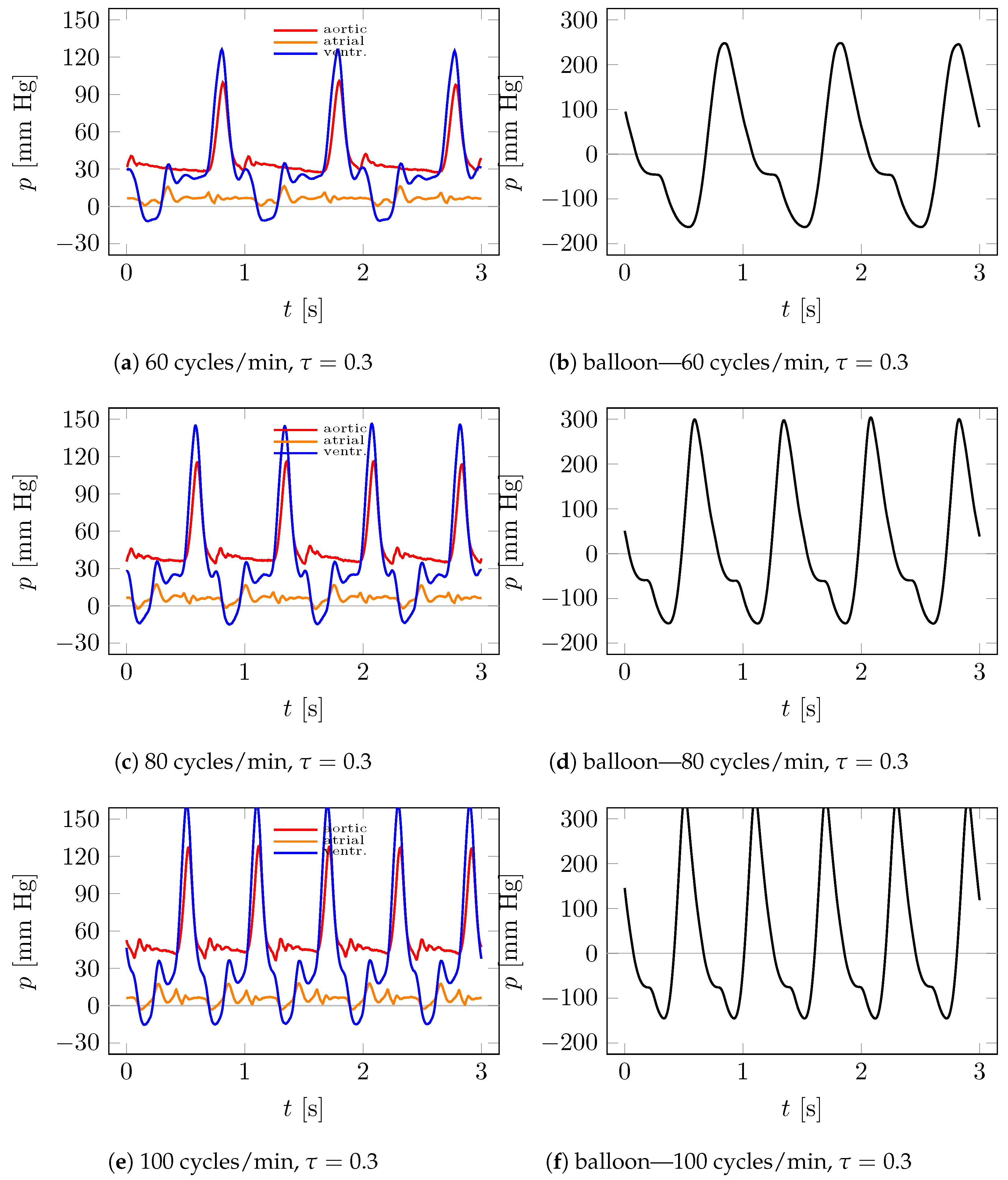
  • Without reduction of the flow cross-sectional area (minimum pressure in the aorta about 30 mm Hg (Figure 9 and Figure 10)); and
  • With a reduced cross-sectional area of the adjustable valve (minimum aortic pressure approximately 45 mm Hg (Figure 11 and Figure 12)).
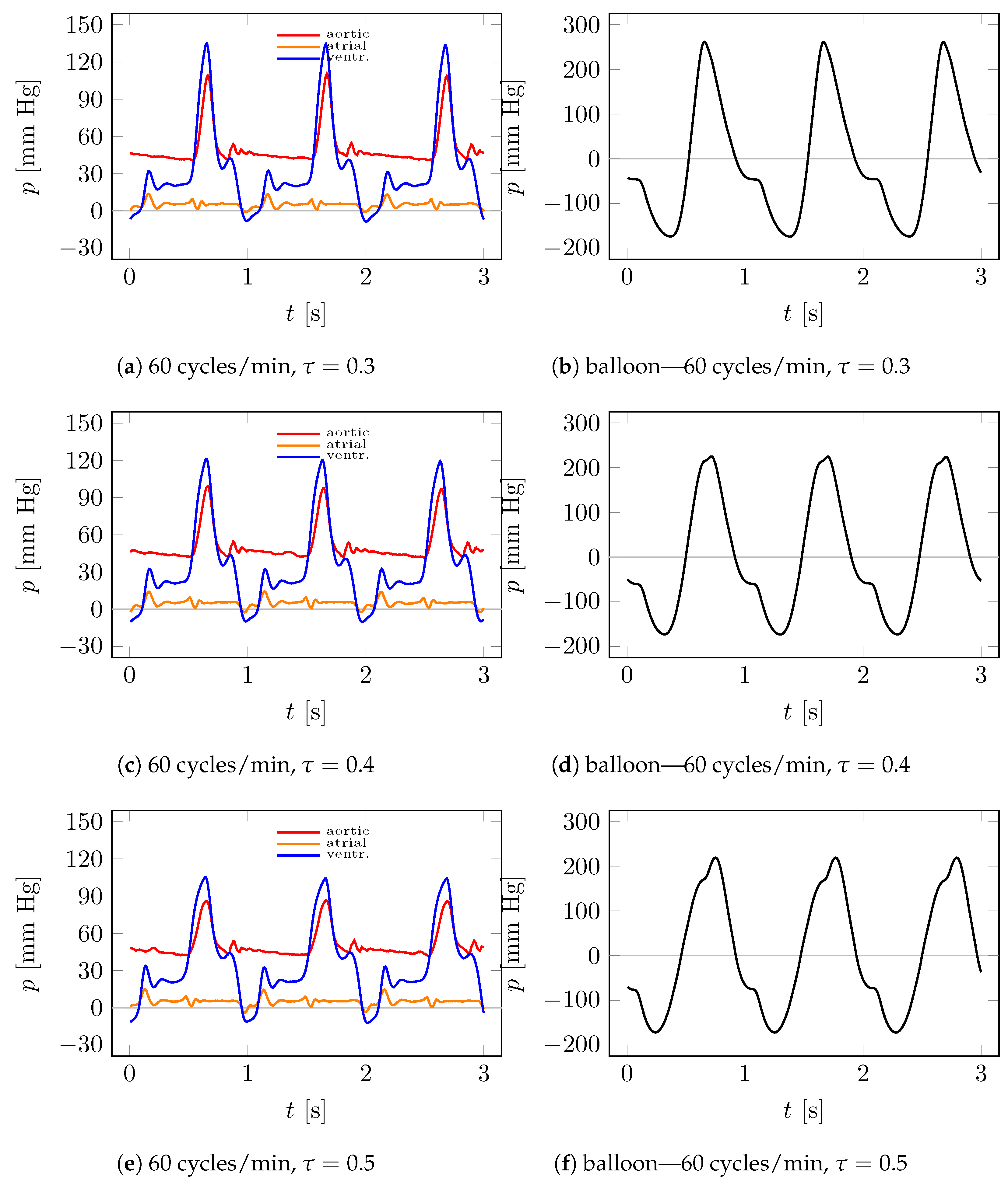
For the case of additional resistance, hydraulic system tests were performed using the operation of a helium-fed ventricular balloon by an external system with an operating frequency of 60, 80, and 100 cycles per minute in order to pump the fluid. The inflation t i and deflation t d times of the ventricular and valve balloons were also varied at a ratio of τ ,
τ = t i t i + t d ,
in the range from 0.25 to 0.5. Below are examples of test results for the values of τ = 0.3 , 0.4, and 0.5.
Depending on the ratio τ of the inflation and deflation times of the ventricular and valve balloons (systolic to diastolic time of the heart), the maximum aortic pressure changes. For τ = 0.3 at a heart rate of 60 cycles/minute, the maximum aortic pressure is 101 mm Hg (Figure 9a), while for τ = 0.4 it is about 87 mm Hg (Figure 9c), and for τ = 0.5 it is about 75 mm Hg (Figure 9e). In contrast, the minimum aortic pressure hardly changes and is at about 30 mm Hg (Figure 9a,c,e). The maximum pressure in the heart chambers with τ being 0.3, 0.4, 0.5 is, respectively, 127 mm Hg (Figure 9a), 109 mm Hg (Figure 9c) and 94 mm Hg (Figure 9e). The gas pressure in the pneumatic supply line close to the balloons varies between 163 and + 248 mm Hg (Figure 9b,d,f).
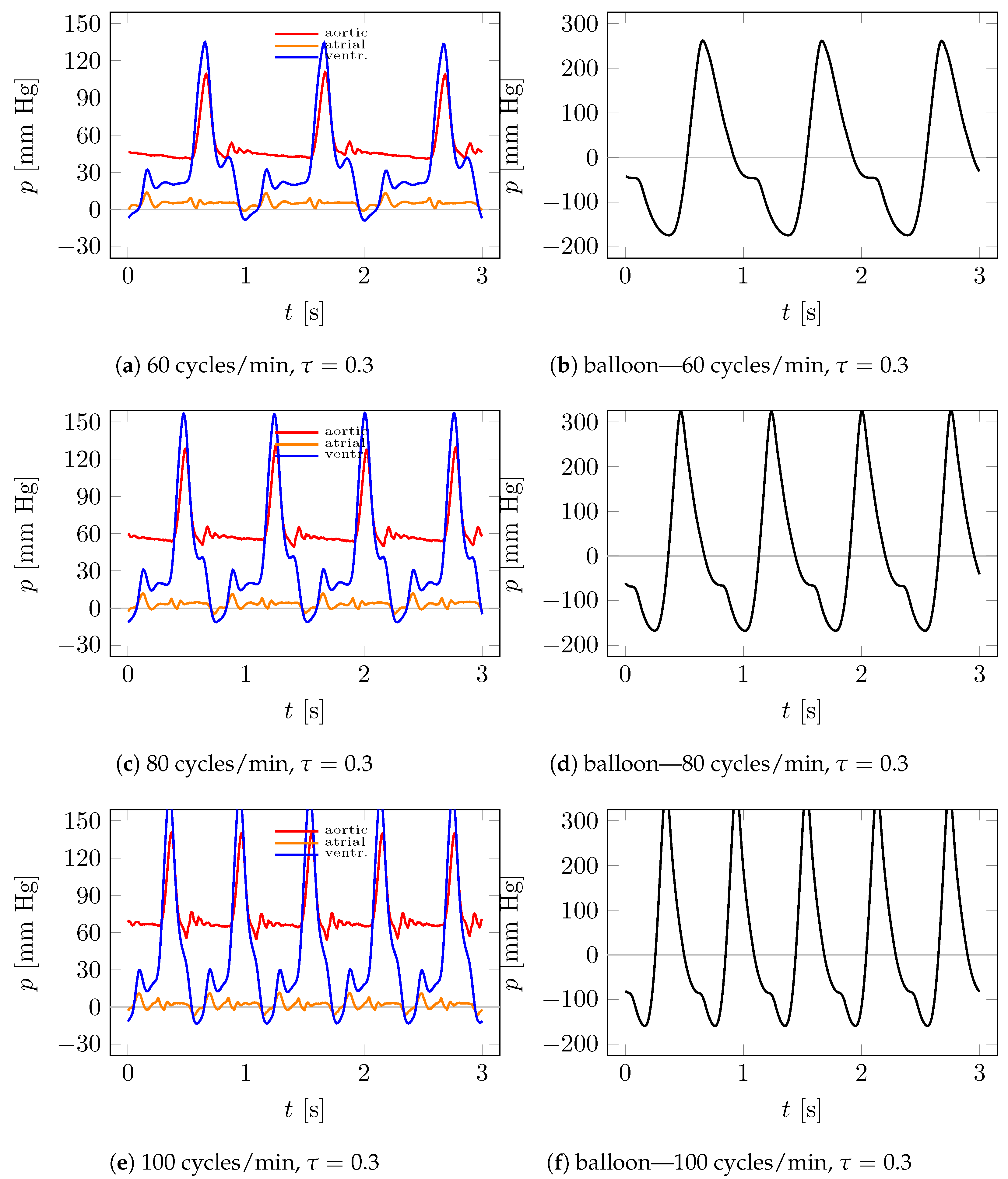
If the operating frequency is increased in the system, this increases the fluid pressure in the aorta and ventricle, as well as the balloon gas pressure. The fluid pressure in the aorta for a heart rate of 80 cycles/min and τ = 0.3 was 117 mm Hg (Figure 10c), and for a heart rate of 100 cycles/min, it was about 128 mm Hg (Figure 10e). The maximum fluid pressure in the chambers was also higher at 147 mm Hg for 80 cycles/min (Figure 10c) and 163 mm Hg for 100 cycles/min (Figure 10e), respectively. Depending on the frequency of the external system, the flow rate varied from about 1.5 kg/min for 60 cycles per minute, to about 2 kg/min for 80 cycles per minute, to about 2.5 kg/min for 100 cycles per minute.
For the case of a hydraulic system with additional flow resistance, hydraulic system tests were also performed using the operation of a helium-fed ventricular balloon by a portable external system to pump the fluid, applying additional flow resistance by reducing the flow cross-sectional area of the hydraulic valve (valve (7) in Figure 5). Tests on the heart model were performed for operating frequencies of 60, 80, and 100 cycles per minute. The test results for τ values of 0.3, 0.4, and 0.5 are shown below.
Depending on the value of τ , the maximum aortic pressure varies. For τ = 0.3 at a heart rate of 60 cycles/minute, the maximum aortic pressure is 110 mm Hg (Figure 11a); for τ = 0.4 , about 100 mm Hg (Figure 11c); and for τ = 0.5 , about 87 mm Hg (Figure 11e). In contrast, the minimum aortic pressure again hardly changes and is at about 45 mm Hg (Figure 11a,c,e). The maximum pressure in the ventricle depending on τ = 0.3 , 0.4, 0.5, respectively, was about 135 mm Hg (Figure 11a), approximately 122 mm Hg (Figure 11c), and approximately 106 mm Hg (Figure 11e).
Increasing the operating frequency in the system increases the fluid pressure in the aorta and ventricle, as well as the balloon gas pressure. The maximum fluid pressure reported in the aorta for a heart rate of 80 cycles/min and τ = 0.3 was 132 mm Hg (Figure 12c), and for a heart rate of 100 cycles/min, it was about 141 mm Hg (Figure 12e). The maximum fluid pressure in the chambers was also higher, at 158 mm Hg for 80 cycles/min (Figure 12c) and 174 mm Hg for 100 cycles/min (Figure 12e), respectively. Depending on the operating frequency of the external feed system, the flow rate varied from about 1.5 kg/min for 60 cycles/min, to about 1.75 kg/min for 80 cycles/min, to about 2 kg/min for 100 cycles/min.
Based on the results of the study, it can be observed that the flow rate varies, with the frequency of the portable external balloon pumping system in a range up to 2.5 kg/min for 100 cycles/min at low flow resistance. With increasing flow resistance in the hydraulic system, pressures in the heart chamber and aorta increase, while flow rates decrease.
According to heart rate synchronization, the device is appropriate for patients with heart rates below 100 cycles per minute. The tests were performed at the most common frequencies of the human heart (i.e., 60, 80, 100 cycles per minute). However, in the next stages of the study, measurements will be made of the performance of ventricular and valve balloons supplied by an external pumping system at higher frequencies, up to 160 cycles per minute.

5. Conclusions

The designed and manufactured test stand makes it possible to investigate the pumping of artificial blood in a model system with an artificial heart, using a set of ventricular and valve balloons. Moreover, the stand ensures that the parameters of the heart have similar values to those of a human heart. It is possible to study different states of work, at different frequencies of operation. On the realistically reconstructed geometry of the heart, it is possible to reproduce conditions typical of patients with stage D heart failure accompanied by residual mitral regurgitation and thus pulmonary hypertension. It is also possible to measure pressures for different flow rates, which are generated by a portable pumping system at different operating frequencies. The studies conducted show that increasing the flow resistance increases the pressure in the heart chambers and decreases the flow rate.
Most importantly, the innovative implantable device, in the form of a set of two balloons for left ventricular support, is able to increase the stroke volume into the aorta through the aortic valve during the systolic phase and to occlude or completely replace the mitral valve. In addition, balloon sizes can be adjusted to match the size of the individual heart chambers. The pulsatile action of the balloons is forced by a suction–discharge device, part of a portable pumping system, and is controlled by a control system in the form of an ODROID computer, which ensures synchronization according to the heart cycle through ECG measurements and continuous processing. Finally, the design of the device allows it to be implanted into the heart chamber in a folded state through the heart apex by means of a minimally invasive implantation. This permits a significant reduction in hospitalization time, even for patients with end-stage heart failure associated with mitral regurgitation and pulmonary hypertension.

Author Contributions

R.J.: conceptualization; methodology; data curation; visualization, investigation, validation. K.T.: conceptualization; formal analysis; methodology; supervision; project administration; investigation; writing—original draft. L.D.: conceptualization; methodology; data curation; visualization, investigation. J.R.: conceptualization; methodology; medical supervision. All authors have read and agreed to the published version of the manuscript.

Funding

This work was supported by the National Centre for Research and Development, Poland, POIR.01.01.01-00-1026/18.

Institutional Review Board Statement

This study was executed in strict accordance with the recommendations for Good Clinical Practice. The protocol was approved by the Independent Bioethical Committee with the permission number NNKBN 167/2017.

Informed Consent Statement

Informed consent was obtained from all subjects involved in the study.

Data Availability Statement

The data presented in this study are available on request from the corresponding author.

Conflicts of Interest

The authors declare that they have no known competing financial interest or personal relationships that could have appeared to influence the work reported in this article.

References

  1. Benjamin, E.J.; Blaha, M.J.; Chiuve, S.E.; Cushman, M.; Das, S.R.; Deo, R.; De Ferranti, S.D.; Floyd, J.; Fornage, M.; Gillespie, C.; et al. Heart disease and stroke statistics—2017 update: A report from the American heart association. Circulation 2017, 135, 146–603. [Google Scholar] [CrossRef] [PubMed]
  2. Li, Y.; Xi, Y.; Wang, H.; Sun, A.; Deng, X.; Chen, Z.; Fan, Y. A new way to evaluate thrombotic risk in failure heart and ventricular assist devices. Med. Nov. Technol. Devices 2022, 16, 100135. [Google Scholar] [CrossRef]
  3. Yancy, C.W.; Januzzi, J.L.; Allen, L.A.; Butler, J.; Davis, L.L.; Fonarow, G.C.; Ibrahim, N.E.; Jessup, M.; Lindenfeld, J.; Maddox, T.M.; et al. 2021 update to the 2017 ACC expert consensus decision pathway for optimization of heart failure treatment: Answers to 10 pivotal issues about heart failure with reduced ejection fraction: A report of the American College of Cardiology Solution Set Oversight Committee. J. Am. Coll. Cardiol. 2021, 77, 772–810. [Google Scholar] [CrossRef]
  4. Slaughter, M.S.; Rogers, J.G.; Milano, C.A.; Russell, S.D.; Conte, J.V.; Feldman, D.; Sun, B.; Tatooles, A.J.; Delgado, R.M., III; Long, J.W.; et al. Advanced heart failure treated with continuous-flow left ventricular assist device. N. Engl. J. Med. 2009, 361, 2241–2251. [Google Scholar] [CrossRef] [PubMed] [Green Version]
  5. Mancini, D.; Colombo, P.C. Left ventricular assist devices: A rapidly evolving alternative to transplant. J. Am. Coll. Cardiol. 2015, 65, 2542–2555. [Google Scholar] [CrossRef] [Green Version]
  6. Quader, M.; Toldo, S.; Chen, Q.; Hundley, G.; Kasirajan, V. Heart transplantation from donation after circulatory death donors: Present and future. J. Card. Surg. 2020, 35, 875–885. [Google Scholar] [CrossRef]
  7. Heidenreich, P.A.; Albert, N.M.; Allen, L.A.; Bluemke, D.A.; Butler, J.; Fonarow, G.C.; Ikonomidis, J.S.; Khavjou, O.; Konstam, M.A.; Maddox, T.M.; et al. Forecasting the impact of heart failure in the United States. A policy statement from the American heart association. Circ. Heart Fail. 2013, 6, 606–619. [Google Scholar] [CrossRef] [Green Version]
  8. Berk, Z.B.K.; Zhang, J.; Chen, Z.; Tran, D.; Griffith, B.P.; Wu, Z.J. Evaluation of in vitro hemolysis and platelet activation of a newly developed maglev LVAD and two clinically used LVADs with human blood. Artif. Organs 2019, 43, 870–879. [Google Scholar] [CrossRef] [PubMed]
  9. Garbade, J.; Bittner, H.B.; Barten, M.J.; Mohr, F.-W. Current trends in implantable left ventricular assist devices. Cardiol. Res. Pract. 2011, 2011, 290561. [Google Scholar] [CrossRef] [Green Version]
  10. Kafagy, D.H.; Dwyer, T.W.; McKenna, K.L.; Mulles, J.P.; Chopski, S.G.; Moskowitz, W.B.; Throckmorton, A.L. Design of axial blood pumps for patients with dysfunctional fontan physiology: Computational studies and performance testing. Artif. Organs 2015, 39, 34–42. [Google Scholar] [CrossRef]
  11. Ward, S.T.; Liang, Q.; Pagani, F.D.; Zhang, M.; Kormos, R.L.; Aaronson, K.D.; Althouse, A.D.; Nallamothu, B.K.; Likosky, D.S. A roadmap for evaluating the use and value of durable ventricular assist device therapy. J. Heart Lung Transplant. 2018, 37, 146–150. [Google Scholar] [CrossRef]
  12. Roth, G.A.; Mensah, G.A.; Johnson, C.O.; Addolorato, G.; Ammirati, E.; Baddour, L.M.; Barengo, N.C.; Beaton, A.Z.; Benjamin, E.J.; Benziger, C.P.; et al. Global Burden of Cardiovascular Diseases and Risk Factors, 1990–2019: Update from the GBD 2019 Study. J. Am. Coll. Cardiol. 2020, 76, 2982–3021. [Google Scholar] [CrossRef] [PubMed]
  13. Friedrich, E.B.; Böhm, M. Management of end stage heart failure. Heart 2007, 93, 626–631. [Google Scholar] [CrossRef] [Green Version]
  14. Chaudhry, S.P.; Stewart, G.C. Advanced heart failure: Prevalence, natural history, and prognosis. Heart Fail. Clin. 2016, 12, 323–333. [Google Scholar] [CrossRef]
  15. Farrar, D.J.; Hill, J.D.; Gray, L.A., Jr.; Pennington, D.G.; McBride, L.R.; Pierce, W.S.; Pae, W.E.; Glenville, B.; Ross, D.; Galbraith, T.A.; et al. Heterotopic prosthetic ventricles as a bridge to cardiac transplantation. N. Engl. J. Med. 1988, 318, 333–340. [Google Scholar] [CrossRef]
  16. Sawa, Y. Current status of third-generation implantable left ventricular assist devices in Japan, Duraheart and HearWare. Surg. Today 2015, 45, 672–681. [Google Scholar] [CrossRef]
  17. Hrobowski, T.; Lanfear, D.E. Ventricular assist devices: Is destination therapy a viable alternative in the non-transplant candidate? Curr. Heart Fail. Rep. 2013, 10, 101–107. [Google Scholar] [CrossRef] [PubMed] [Green Version]
  18. Available online: https://www.abiomed.com/products-and-services/impella (accessed on 28 May 2023).
  19. Abrams, D.; Combes, A.; Brodie, D. Extracorporeal membrane oxygenation in cardiopulmonary disease in adults. J. Am. Coll. Cardiol. 2014, 63, 2769–2778. [Google Scholar] [CrossRef] [Green Version]
  20. Takayama, H.; Truby, L.; Koekort, M.; Uriel, N.; Colombo, P.; Mancini, D.M.; Jorde, U.P.; Naka, Y. Clinical outcome of mechanical circulatory support for refractory cardiogenic shock in the current era. J. Heart Lung Transplant. 2013, 32, 106–111. [Google Scholar] [CrossRef] [PubMed]
  21. Sarna, J.; Kustosz, R.; Major, R.; Lackner, J.M.; Major, B. Polish artificial heart—New coatings, technology, diagnostics. Bull. Pol. Acad. Sci. Tech. Sci. 2010, 58, 329–335. [Google Scholar] [CrossRef]
  22. Available online: https://www.levitronix.com/ (accessed on 28 May 2023).
  23. Available online: https://www.cardiovascular.abbott/ (accessed on 28 May 2023).
  24. Available online: http://www.cardiacassist.com (accessed on 28 May 2023).
  25. Available online: https://global.medtronic.com/ (accessed on 28 May 2023).
  26. Stewart, G.C.; Givertz, M.M. Mechanical circulatory support for advanced heart failure: Patients and technology in evolution. Circulation 2012, 125, 1304–1315. [Google Scholar] [CrossRef]
  27. Chaudhry, S.P.; DeVore, A.D.; Vidula, H.; Nassif, M.; Mudy, K.; Birati, E.Y.; Gong, T.; Atluri, P.; Pham, D.; Sun, B.; et al. Left ventricular assist devices: A primer for the general cardiologist. J. Am. Heart Assoc. 2022, 11, e027251. [Google Scholar] [CrossRef] [PubMed]
  28. Han, J.; Trumble, D.R. Cardiac assist devices: Early concepts, current technologies, and future innovations. Bioengineering 2019, 6, 18. [Google Scholar] [CrossRef] [PubMed] [Green Version]
  29. Kirklin, J.K.; Naftel, D.C.; Pagani, F.D.; Kormos, R.L.; Stevenson, L.W.; Blume, E.D.; Miller, M.A.; Baldwin, J.T.; Young, J.B. Sixth INTERMACS annual report: A 10,000-patient database. J. Heart Lung Transplant. 2014, 33, 555–564. [Google Scholar] [CrossRef] [PubMed]
  30. Teuteberg, J.J.; Clevel, J.C., Jr.; Cowger, J.; Higgins, R.S.; Goldstein, D.J.; Keebler, M.; Kirklin, J.K.; Myers, S.L.; Salerno, C.T.; Stehlik, J.; et al. The Society of Thoracic Surgeons Intermacs 2019 annual report: The changing landscape of devices and indications. Ann. Thorac. Surg. 2020, 109, 649–660. [Google Scholar] [CrossRef] [PubMed] [Green Version]
  31. Walther, C.P.; Niu, J.; Winkelmayer, W.C.; Cheema, F.H.; Nair, A.P.; Morgan, J.A.; Fedson, S.E.; Deswal, A.; Navaneethan, S.D. Implantable ventricular assist device use and outcomes in people with end-stage renal disease. J. Am. Heart Assoc. 2018, 7, e008664. [Google Scholar] [CrossRef] [Green Version]
  32. Tesch, K.; Kaczorowska, K. The discrete-continuous, global optimisation of an axial flow blood pump, Flow. Turbul. Combust. 2019, 104, 777–793. [Google Scholar] [CrossRef] [Green Version]
  33. Torner, B.; Konnigk, L.; Abroug, N.; Wurm, H. Turbulence and turbulent flow structures in a ventricular assist device—A numerical study using the large-eddy simulation. Int. J. Numer. Methods Biomed. Eng. 2021, 37, e3431. [Google Scholar] [CrossRef]
  34. Pleşoianu, F.A.; Pleşoianu, C.E.; Bararu Bojan, I.; Bojan, A.; Ţăruş, A.; Tinică, G. Concept, design, and early prototyping of a low-cost, minimally invasive, fully implantable left ventricular assist device. Bioengineering 2022, 9, 201. [Google Scholar] [CrossRef]
  35. Shah, S.P.; Mehra, M.R. Durable left ventricular assist device therapy in advanced heart failure: Patient selection and clinical outcomes. Indian Heart J. 2016, 68, S45–S51. [Google Scholar] [CrossRef] [Green Version]
  36. Aaronson, K.D.; Slaughter, M.S.; Miller, L.W.; McGee, E.C.; Cotts, W.G.; Acker, M.A.; Jessup, M.L.; Gregoric, I.D.; Loyalka, P.; Frazier, O.H.; et al. Use of an intrapericardial, continuous-flow, centrifugal pump in patients awaiting heart transplantation. Circulation 2012, 125, 3191–3200. [Google Scholar] [CrossRef] [Green Version]
  37. Rogers, J.G.; Pagani, F.D.; Tatooles, A.J.; Bhat, G.; Slaughter, M.S.; Birks, E.J.; Boyce, S.W.; Najjar, S.S.; Jeevanandam, V.; Anderson, A.S.; et al. Intrapericardial left ventricular assist device for advanced heart failure. N. Engl. J. Med. 2017, 376, 451–460. [Google Scholar] [CrossRef]
  38. Shi, J.; Yu, X.; Liu, Z. A review of new-onset ventricular arrhythmia after left ventricular assist device implantation. Cardiology 2022, 147, 315–327. [Google Scholar] [CrossRef]
  39. Vollkron, M.; Voitl, P.; Ta, J.; Wieselthaler, G.; Schima, H. Suction events during left ventricular support and ventricular arrhythmias. J. Heart Lung Transplant. 2007, 26, 819–825. [Google Scholar] [CrossRef]
  40. Kafagy, D.H.; Dwyer, T.W.; McKenna, K.L.; Mulles, J.P.; Chopski, S.G.; Moskowitz, W.B.; Throckmorton, A.L. Mechanical circulatory support devices for acute right ventricular failure. Circulation 2017, 136, 314–326. [Google Scholar] [CrossRef] [Green Version]
  41. Kassis, H.; Cherukuri, K.; Agarwal, R.; Kanwar, M.; Elapavaluru, S.; Sokos, G.G.; Moraca, R.J.; Bailey, S.H.; Murali, S.; Benza, R.L.; et al. Significance of residual mitral regurgitation after continuous flow left ventricular assist device implantation. JACC Heart Fail. 2017, 5, 81–88. [Google Scholar] [CrossRef]
  42. Kormos, R.L.; Teuteberg, J.J.; Pagani, F.D.; Russell, S.D.; John, R.; Miller, L.W.; Massey, T.; Milano, C.A.; Moazami, N.; Sundareswaran, K.S.; et al. Right ventricular failure in patients with the Heart-Mate II continuous-flow left ventricular assist device: Incidence, risk factors, and effect on outcomes. J. Thorac. Cardiovasc. Surg. 2010, 139, 1316–1324. [Google Scholar] [CrossRef] [Green Version]
  43. Han, J.J.; Acker, M.A.; Atluri, P. Left ventricular assist devices: Synergistic model between technology and medicine. Circulation 2018, 138, 2841–2851. [Google Scholar] [CrossRef]
  44. Rose, E.A.; Gelijns, A.C.; Moskowitz, A.J.; Heitjan, D.F.; Stevenson, L.W.; Dembitsky, W.; Long, J.W.; Ascheim, D.D.; Tierney, A.R.; Levitan, R.G.; et al. Long-term use of a left ventricular assist device for end-stage heart failure. N. Engl. J. Med. 2001, 345, 1435–1443. [Google Scholar] [CrossRef] [PubMed]
  45. PCT Application, Implantable Left Ventricular Assist Device and System for Ventricular-assist for Use in Patients with End-Stage Heart Failure PCT/PL2021/050004. Available online: https://patentscope.wipo.int/search/en/detail.jsf?docId=WO2021162564 (accessed on 28 May 2023).
  46. Tesch, K.; Jasinski, R.; Dabrowski, L.; Rogowski, J. Experimental investigation of the performance of an innovative implantable left ventricular assist device—Proof of concept. Appl. Sci. 2023, 13, 973. [Google Scholar] [CrossRef]
  47. Available online: https://www.slicer.org/ (accessed on 28 May 2023).
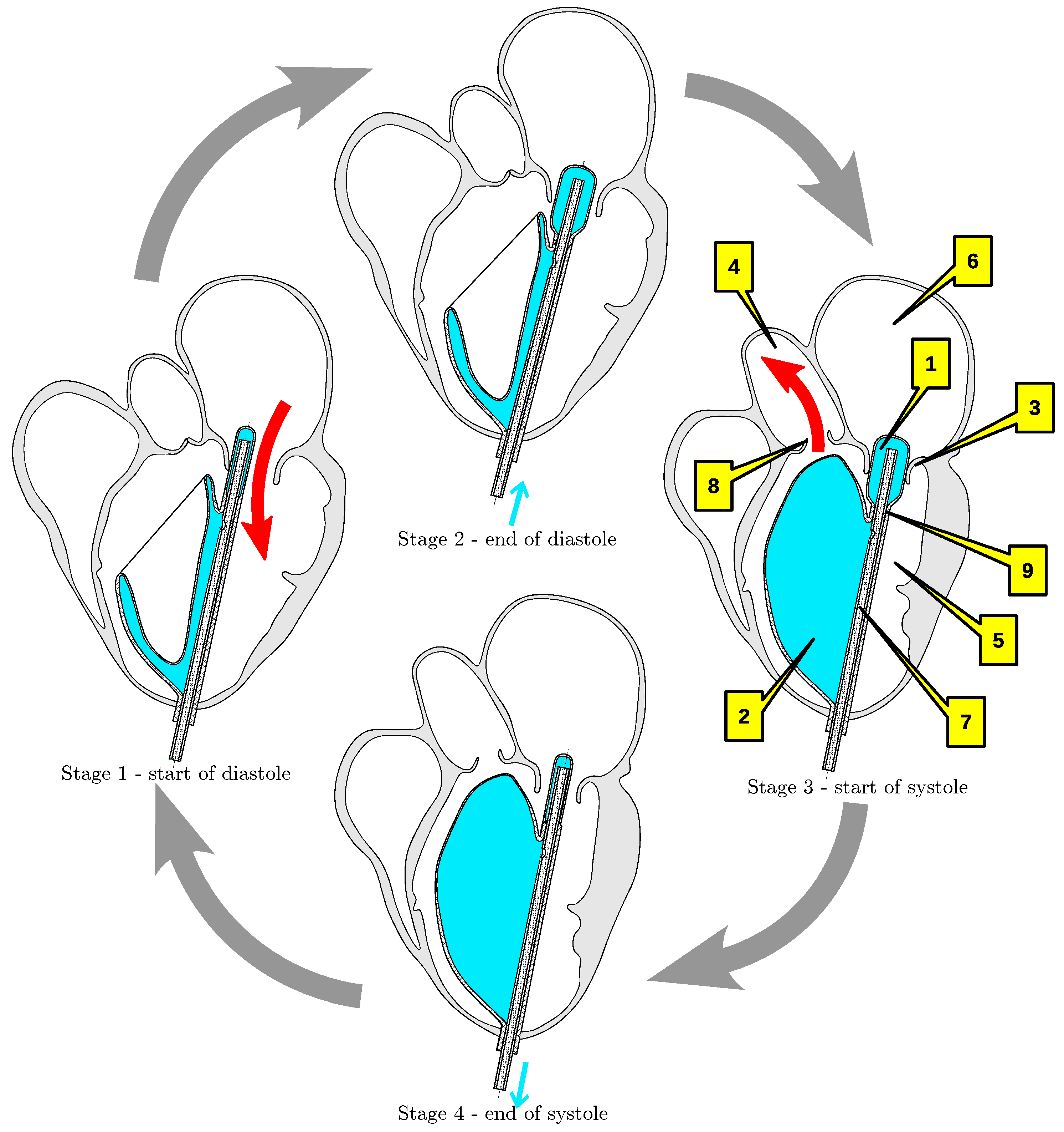
Figure 1. Principle of operation: (1)—valve balloon, (2)—ventricular balloon, (3)—mitral valve, (4)—aorta, (5)—left ventricle, (6)—left atrium, (7)—pneumatic line, (8)—aortic valve, (9)—narrowing.
Applsci 13 07785 g001
Figure 2. Application in a folded state.
Applsci 13 07785 g002
Figure 3. Reconstruction process.
Applsci 13 07785 g003
Figure 4. Reconstructed geometry. (a) Initial design of the balloon set against the background of the three reconstructed heart models. (b) Balloon set model incorporated into a model of the left ventricle, atrium, and aorta for LVEF = 30% in systole and diastole: (1)—artificial valve, (2)—cylindrical orifice, (3)—single conduit to the atrium.
Applsci 13 07785 g004
Figure 5. Experimental stand: (1)—flexible left heart; (2)—flow reservoir replacing the pulmonary veins (liquid containers Z2 in Figure 6); (3)—pressure sensor (P3 in Figure 6); (4)—aorta pressure sensor (pressure sensor P3 in Figure 6); (5)—flow meter (Q1 in Figure 6); (6)—external helium supply system; (7)—hydraulic valve for changing the flow resistance in the hydraulic system; (8)—gas (helium) pressure sensor near balloons; (9)—atrium fluid pressure sensor (pressure sensor PP in Figure 6).
Applsci 13 07785 g005
Figure 6. Diagram of the hydraulic and pneumatic test stand system: A1, A2, A3—compensation vessels simulating the flexibility of the human circulatory system; PHe—helium pressure sensor close to the balloons; P1—pulmonary veins pressure sensor; P3—aorta pressure sensor, PP—atrium fluid pressure sensor; PK—fluid ventricular pressure sensor; Q1—mass flowmeter; Z1, Z2—liquid containers; ZZ—mechanical valve.
Applsci 13 07785 g006
Figure 7. External gas supply system for the balloon system, consisting of a servo-driven reciprocating compressor with a crank mechanism: (1)—reciprocating compressor, (2)—Mitsubishi servo motor; (3)—Mitsubishi servo amplifier; (4)—ODROID computer; (5)—battery pack.
Applsci 13 07785 g007
Figure 8. Operation of the ventricular and valve balloons.
Applsci 13 07785 g008
Figure 9. Experimental results—aortic, atrial, ventricular, and balloon pressure distributions (no resistance).
Applsci 13 07785 g009
Figure 10. Experimental results for different cycles per minute—aortic, atrial, ventricular, and balloon pressure distributions (no resistance).
Applsci 13 07785 g010
Figure 11. Experimental results—aortic, atrial, ventricular, and balloon pressure distributions (additional resistance).
Applsci 13 07785 g011
Figure 12. Experimental results for different cycles per minute—aortic, atrial, ventricular, and balloon pressure distributions (additional resistance).
Applsci 13 07785 g012
Disclaimer/Publisher’s Note: The statements, opinions and data contained in all publications are solely those of the individual author(s) and contributor(s) and not of MDPI and/or the editor(s). MDPI and/or the editor(s) disclaim responsibility for any injury to people or property resulting from any ideas, methods, instructions or products referred to in the content.