Article

A Dual-Channel End-to-End Speech Enhancement Method Using Complex Operations in the Time Domain

1
State Key Laboratory of Intelligent Vehicle Safety Technology, Chongqing 401122, China
2
School of Communication and Information Engineering, Chongqing University of Posts and Telecommunications, Chongqing 400065, China
3
Intelligent Speech and Audio Research Laboratory, Chongqing University of Posts and Telecommunications, Chongqing 400065, China
*
Author to whom correspondence should be addressed.
Appl. Sci. 2023, 13(13), 7698; https://doi.org/10.3390/app13137698
Submission received: 28 February 2023 / Revised: 19 June 2023 / Accepted: 26 June 2023 / Published: 29 June 2023

Abstract

:
This study investigates the utilization of complex operations to perform multichannel speech enhancement in the time domain using a neural network. Previous studies have demonstrated the advantages of incorporating complex operations when designing neural networks; however, they have solely focused on frequency-domain enhancement techniques. In contrast, our research study presents an end-to-end approach to perform speech enhancement in the time domain. We used the Hilbert transform to intelligently generate complex time-domain waveforms as inputs to the network. This allowed us to create an end-to-end approach that explores spatial information. To handle the complexity of the inputs, we developed a complex neural adaptive beamformer (CNAB). We utilized complex shared long short-term memory (LSTM), split-LSTM, and complex convolutions to generate the beamforming output. Following this, we developed a complex full convolutional network (CFCN) to enhance the beamforming output. We leveraged complex dilated convolutions to model the long-term temporal dependencies of speech. By cascading the CNAB and CFCN, we created the final end-to-end time-domain enhancement network, named CNABCFCN. We trained and tested CNABCFCN using the deep noise suppression (DNS) challenge dataset. Our results demonstrate the advantages of using complex operations over the baseline model. Furthermore, the proposed CNABCFCN performed better in terms of both objective and subjective measures compared with other networks.

1. Introduction

Speech enhancement refers to a set of signal processing techniques aimed at improving the quality and intelligibility of speech signals by suppressing interference signals, such as background noise and reverberation. External noise and environmental reverberation can negatively impact speech signals received by microphones, resulting in a low signal-to-noise ratio (SNR) that impairs human hearing and the accuracy of systems used in human–computer interactions, such as speech recognition and speech wake-up applications [1]. Therefore, the study of speech enhancement techniques is critical to enhancing speech signals and improving overall system performance.
Traditional single-channel speech enhancement algorithms rely on signal processing techniques such as time-domain, frequency-domain, spatial-domain, and high-order statistics. However, it is challenging to adapt these methods to changing acoustic scenarios [2]. Over the past decade, deep learning-based algorithms have achieved significant success in speech enhancement. In particular, several methods that exploit time–frequency-domain feature mapping have made marked progress in noise reduction, as demonstrated in [3,4,5]. Nevertheless, these approaches typically ignore the modeling of speech signal phase information. Unlike time–frequency-domain-based methods that only focus on magnitude regression using the short-time Fourier transform (STFT), some recent methods [6,7] reconstruct the speech signal by directly processing the time-domain waveform. Deep Complex Convolution Recurrent Network for Phase-Aware Speech Enhancement (DCCRN) [8] innovatively proposes complex number-domain features as input features to neural networks and demonstrates great potential in noise reduction. The DCCRN design simulates complex value operations using a complex number network. In DCCRN, the input of the network is both the real and imaginary (RI) information of the complex STFT. By concurrently considering the amplitude and phase of the STFT, DCCRN significantly improves the performance of speech enhancement models.
In addition, multichannel speech enhancement generally outperforms single-channel speech enhancement due to additional spatial information provided by the number of available microphones [9]. There are two main types of multichannel approaches: time-domain and frequency-domain approaches. Classic signal processing-based techniques such as beamforming have been used, including minimum variance distortionless response (MVDR) [10] and generalized sidelobe canceller (GSC) formulation [11], where the energy of the signal at the output is minimized, while the energy in the target direction is maintained. A beamformer requires a target steering vector [12], and in most cases, the method for estimating the steering vector is based on direction of arrival (DOA) estimation [13]. However, the estimation is not error-free and can significantly impact the performance of the beamforming technique.
Recently, time-domain convolutional denoising autoencoders (TCDAEs) [9] have been designed; they exploit the delay between multichannel signals to directly extract the characteristics of time-domain signals using an encoder–decoder network. Although TCDAEs exhibit better performance than single-channel DAEs [14], they use limited noise types, which results in suboptimal performance. Wang et al., proposed a complex spectral mapping approach combined with minimum variance distortionless response (MVDR) beamforming, which produces beamforming filter coefficients based on the covariance matrix of the signal and noise [15]. Alternatively, Li et al. [16] proposed neural network adaptive beamforming (NAB), which learns beamforming filters without estimating the direction of arrival (DOA) or computing the covariance matrix. NAB outperforms conventional beamforming methods but is applied to an adaptive neural network in the time–frequency domains. The filter-and-sum network (FaSNet) by Luo et al., performs time-domain filter-and-sum beamforming at the frame level and directly estimates beamforming filters with a neural network [17]. The beamforming filters are then applied to the time-domain input signal of each frame, similar to the beamforming method.
In this study, we propose a dual-channel speech enhancement technique based on complex time-domain mapping inspired by adaptive neural network beamforming and complex time-domain operations. To fully utilize the information from the two speech channels in the time domain, we developed a complex neural network adaptive beamformer (CNAB) approach to predict complex time-domain beamforming filter coefficients. During the training process, the coefficients are updated according to changes in the noisy dataset, which differs from the fixed-filter approach of previous studies [18,19]. Additionally, the real and imaginary (RI) parts of the beamforming filter coefficients estimated by the CNAB perform complex convolution and summation operations on the input to each channel. The resulting complex time-domain beamforming output is then used as input to the local complex full convolutional network (CFCN) to predict the complex time-domain information of the enhanced speech. The primary contributions of this study are as follows:
  • To enable time-domain complex operations and prepare the input of the network, we utilized the Hilbert transform to construct a complex signal.
  • We developed a complex neural network adaptive beamforming technique that utilizes complex inputs to perform speech enhancement.
  • We developed a complex full convolutional network that takes the output of the CNAB as input to enhance speech.
  • By combining all of these components, we designed and tested a dual-channel complex enhancement network that performs speech denoising in the time domain.
The rest of the paper is structured as follows: Section 2 presents the proposed algorithm, which covers the preparation of complex inputs, the loss function, the structure of the CNAB, and the structure of the CFCN. In Section 3, we describe the experimental settings, including dataset creation, different scenarios, and network parameters. Section 4 presents the experimental results and associated discussions on the performance of the proposed network compared with the baseline and different models in various scenarios. Finally, we draw conclusions and suggest topics for future research in Section 5.

2. Algorithm Description

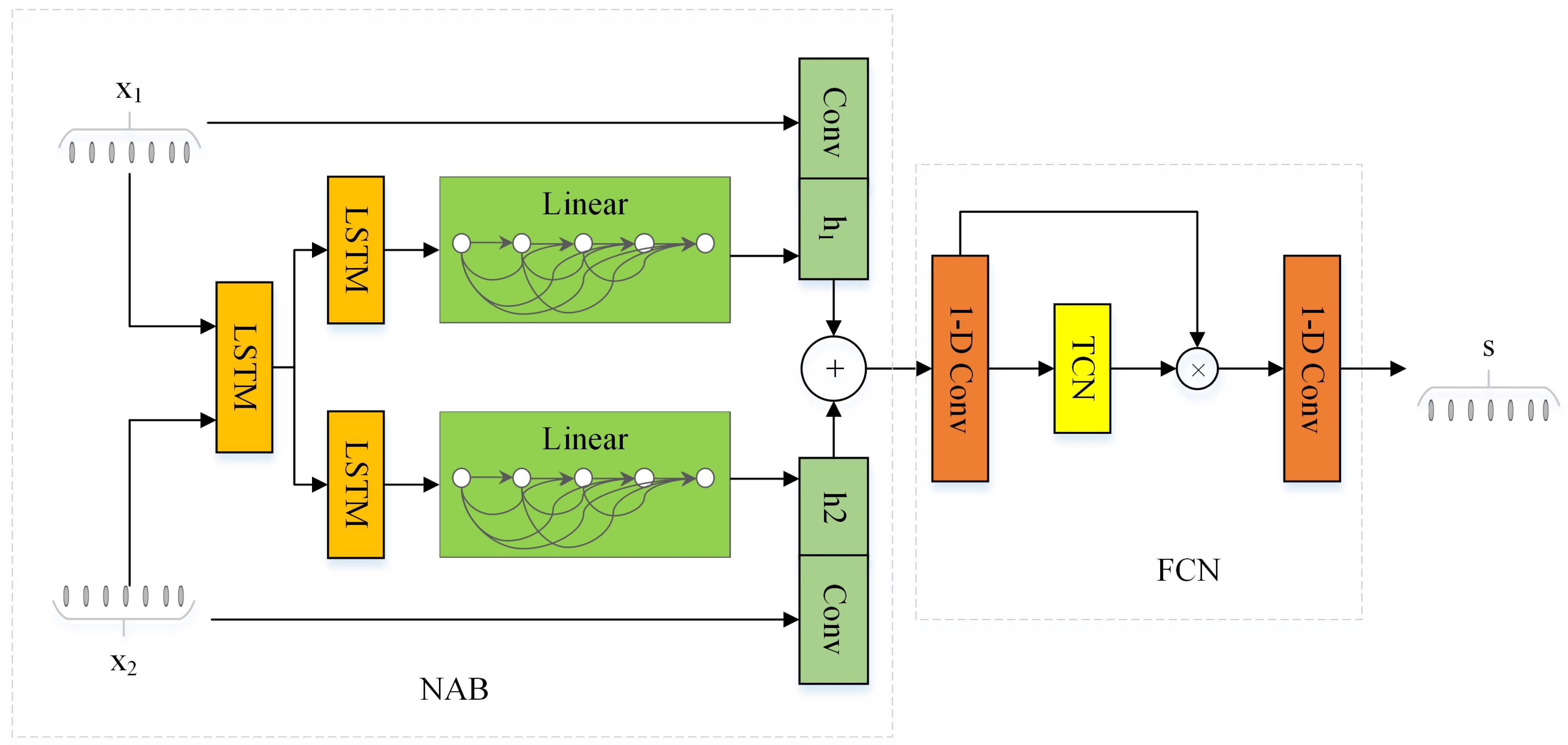
In this section, we introduce a dual-channel, end-to-end, time-domain speech enhancement method that employs complex operations, as illustrated in Figure 1. This approach comprises two stages: complex neural network adaptive beamformer (CNAB) and complex fully convolutional network (CFCN). In the first stage, the CNAB performs preliminary speech enhancement on the dual-channel noisy speech. In the second stage, the CFCN produces the final high-quality speech.

2.1. Analysis of the Signal Characteristics at the Input

In this section, we provide the details to show how to generate the complex inputs in time domain.
The received signals by each microphone in time domain are
x 0 ( k ) [ t ] = s 0 ( k ) [ t ] + n 0 ( k ) [ t ] ,
x 1 ( k ) [ t ] = s 1 ( k ) [ t ] + n 1 ( k ) [ t ] ,
where t 0 , 1 , , N denotes the sample index in each frame and k 0 , 1 , , M denotes the frame index. The clean speech captured by the two microphones, denoted by s 0 ( k ) [ t ] and s 1 ( k ) [ t ] , respectively, is given by
s 0 ( k ) [ t ] = s ( k ) [ t ] h 0 ( k ) [ n ] ,
s 1 ( k ) [ t ] = s ( k ) [ t ] h 1 ( k ) [ n ] ,
where h 0 ( k ) [ n ] R K × 1 and h 1 ( k ) [ n ] R K × 1 indicate the room impulse responses (RIRs) corresponding to the two microphones; n 0 , 1 , , K 1 denotes the sampling point of the filters; and s ( k ) [ t ] R N × 1 is the sound source. In this study, s 0 ( k ) [ t ] corresponds to the direct path signal in the reference microphone and is utilized as the target [15]. Since the distance between the two microphones is small and they are positioned on the same horizontal line, we select c = 0 as the reference microphone. While noise is also affected by the RIR, it must be eliminated in speech noise reduction tasks, regardless of its form. Therefore, the effect of RIR on noise is generally not explicitly expressed.
In frequency-domain processing, the RI parts are naturally present in spectrograms. However, in the time domain, only real-time speech is available, which poses the first challenge of generating its corresponding imaginary part. In this study, we used the Hilbert transform to construct the analytic signal. The Hilbert transform constructs the analytic function x c a ( k ) [ t ] C N × 1 of a discrete signal, where C is the complex number field. For convenience and because the network operates in a frame-by-frame manner, we omit the frame number (k) and denote x c a ( k ) [ t ] as x c a [ t ] hereafter. For the negative frequency part of the signal spectrum, we apply the following correction:
X c a ( f ) = 2 X c ( f ) , f > 0 X c ( f ) , f = 0 0 , f < 0 = X c ( f ) + s g n ( f ) X c ( f ) ,
where X c a ( f ) R L × 1 and X c ( f ) R L × 1 are the spectra of x c a [ t ] and x c [ t ] , respectively, and subscript c represents the microphone index. The function s g n ( · ) represents the sign function. Thus, the definition of the analytic function x c a [ t ] is
x c a [ t ] = F 1 [ X c ( f ) + s g n ( f ) X c ( f ) ] = F 1 [ X c ( f ) ) + F 1 ( s g n ( f ) ) F 1 ( X c ( f ) ) ] = x c [ t ] + j ( 1 π t x c [ t ] ) = x c [ t ] + j x ^ c [ t ] ,
where F 1 is the inverse Fourier transform. Equation (6) shows that the imaginary part x ^ c [ t ] R N × 1 , which can be obtained with the inverse Fourier transform of the positive half of the frequency spectrum, X c ( f ) . The one-dimensional real signal x c [ t ] R N × 1 is convolved with the impulse response of 1 π t to produce its corresponding imaginary part, and a two-dimensional complex signal x c a [ t ] C N × 1 finally serves as input to the proposed network.

2.2. Loss Function

Unlike traditional end-to-end speech enhancement models that only estimate the real part information in the time domain, our proposed method trains CNABCFCN to recover both the RI parts of clean speech. The loss function used to train the proposed model is
SI-SDR = ( 1 λ ) × 10 log 10 β r × R e ( s a [ t ] ) 2 β r × R e ( s a [ t ] ) R ^ [ t ] 2 + λ × 10 log 10 β i × I m ( s a [ t ] ) 2 β i × I m ( s a [ t ] ) I ^ [ t ] 2 ,
β r = R ^ t T R e ( s a ( t ) ) s a [ t ] 2 = arg   min β r β r × R e ( s a ( t ) ) R ^ [ t ] 2 ,
β i = I ^ [ t ] T I m ( s a ( t ) ) s a [ t ] 2 = arg   min β i β i × I m ( s a ( t ) ) I ^ [ t ] 2 ,
where R e ( · ) and I m ( · ) denote the RI part operations, respectively. Because the features we consider are essentially time-domain information, we adopt the scale-invariant signal-to-distortion ratio (SI-SDR) loss function to train the proposed model, which results in better speech enhancement performance [20]. The RI information of each frame estimated by the CNABCFCN model is denoted by R ^ [ t ] R N × 1 and I ^ [ t ] R N × 1 , respectively. And s a [ t ] is the analytic function of the reference channel that received clean speech s 0 [ t ] . In (7), λ is a constant within [ 0 , 1 ] that weighs RI information. When λ = 0 , the network prefers to use real information to train the network parameters, whereas λ = 1 indicates a preference for using imaginary information to update the network. From the experiments, a good empirical hyperparameter λ = 0.5 was chosen.

2.3. CNAB Architecture

The proposed CNABCFCN framework utilizes complex operations in all CNAB structures. As shown in the first part of Figure 1, the first layer in the CNAB structure consists of a complex LSTM layer, which we call complex shared-LSTM. The Hilbert transform ( x c a [ t ] ) of speech in each channel passes through this layer. Figure 2 demonstrates the rules of complex LSTM used in complex shared-LSTM. The complex operations inside complex LSTM are, explicitly,
L r = L S T M r ( R e ( x c a [ t ] ) ) L S T M r ( I m ( x c a [ t ] ) ) ,
L i = L S T M i ( R e ( x c a [ t ] ) ) + L S T M i ( R e ( x c a [ t ] ) ) ,
L o u t = L r + j L i .
The complex shared-LSTM in the CNAB includes two ordinary LSTM networks, L S T M r and L S T M i , which process the real and imaginary parts of speech, respectively. The feature mappings of the real and imaginary parts are denoted by L r R N × 1 and L i R N × 1 , respectively.
The output of complex LSTM is a complex feature mapping, L o u t C N × 1 . After passing through the shared-LSTM layer, the output is fed into two complex LSTM layers, which correspond to the features of each channel. This process is called complex split-LSTM, and the complex operations are the same as in (10). The outputs of the split-LSTM layers are activated by complex linear functions and serve as the estimated beamforming filters, denoted by h c a [ n ] , as shown in Figure 1. Finally, the original inputs are convolved with the estimated coefficients h c a [ n ] and summed together to produce the output of the CNAB. A detailed explanation of the CNAB will follow.

2.4. Complex Adaptive Spatial Filtering

Traditional beamforming requires the alignment of the received speech signal with the reference microphone due to differences in the time it takes for sound to reach different microphones. The accurate estimation of steering delay τ c plays a crucial role in speech enhancement performance. The proposed CNAB model represents a novel approach to estimating filter coefficients by minimizing a loss function that measures the difference between clean speech and the enhanced one in the time–frequency domains. As a result, the estimation of steering delay τ c is implicit in the estimated filter coefficients. For the k-th frame, the CNAB model’s output is denoted by y a ( k ) [ t ] , expressed in a frame-wise manner as
y a ( k ) [ t ] = ( y r r ( k ) [ t ] y i i ( k ) [ t ] ) + j ( y r i ( k ) [ t ] + y i r ( k ) [ t ] ) ,
where y r r ( k ) [ t ] R N × 1 is the output result of the real feature, expressed as
y r r ( k ) [ t ] = c = 0 C 1 n = 0 N 1 R e ( h c a ( k ) [ n ] ) R e ( x c a ( k ) [ t n ] ) ,
where h c a ( k ) [ n ] C K × 1 is the estimated beamforming coefficient for channel c. To estimate h c a [ n ] , we train the entire CNABCFCN network in a joint manner to produce the filter coefficients of each channel. In Equation (11), the features y i i ( k ) ( t ) , y r i ( k ) ( t ) , and y i r ( k ) ( t ) are defined as in Equation (12), and their specific representations are omitted for simplicity.

2.5. CFCN Architecture

The second part of CNABCFCN consists of a complex fully convolutional neural network, which is illustrated in Figure 3. As defined above, the output of the CNAB is denoted by y a ( k ) [ t ] C N × 1 , where C is the set of complex numbers, k 0 , 1 , , M 1 is the index of each frame, and M is the total number of indices. At this point, y a ( k ) [ t ] is no longer a dual-channel feature but a single-channel complex feature, and it is passed through a 1D convolutional layer. The formulation of the 1D convolution is given by
D r ( k ) = f d c o n v ( R e ( y a ( k ) ) ) ,
D i ( k ) = f d c o n v ( I m ( y a ( k ) ) ) ,
where f d c o n v denotes the feature mapping function of 1D Conv, and D r ( k ) R P × 1 and D i ( k ) R P × 1 denote the real and imaginary outputs of 1D Conv, respectively.
To facilitate the CFCN network in learning the characteristics of time-domain data, the real and imaginary outputs ( D r , D i ) R S × 2 must be normalized as follows:
( N r , N i ) = f n o r m ( ( D r , D i ) ) ,
where f n o r m is the feature mapping function of the layernorm, BatchNorm [21] is used as the layernorm, and ( N r , N i ) R S × 2 are the normalized feature mappings.
The CFCN network uses a complex 1 × 1 convolutional layer to perform complex convolutions on N r and N i , as follows:
C o u t = ( c o n v r ( N r ) c o n v i ( N i ) ) + j ( c o n v r ( N i ) + c o n v i ( N r ) ) .
Equation (15) shows that the complex 1 × 1 convolutional layer is constructed from two one-dimensional convolutional layers, c o n v r and c o n v i , representing the feature mapping functions for the RI parts, respectively. The final output of the complex 1 × 1 convolutional layer is C o u t C T × 1 .
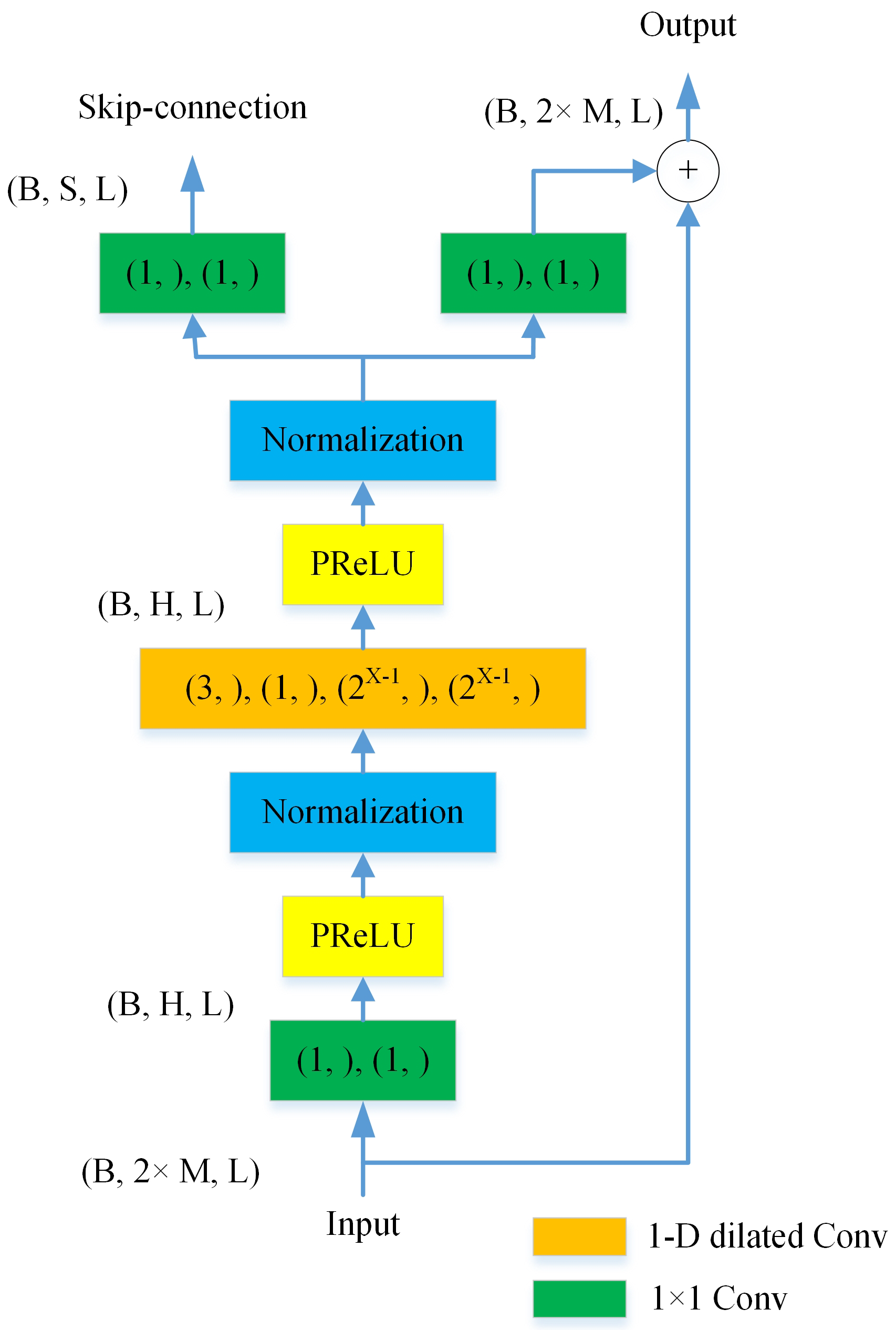
Following the complex convolutional layer, the CNABCFCN network uses 1D dilated convolutional blocks [22]. To maximize the utilization of the temporal context window of the speech signal, the dilation factors of the 1D convolutional blocks in each layer are exponentially increased. The proposed CNABCFCN system repeats X convolutional blocks with dilation factors 1 , 2 , 4 , , 2 X 1 R times. Although we attempted to replace all 1D dilated convolutional blocks with complex convolutional blocks, this approach did not improve the performance of the CNABCFCN model and instead consumed significant computational memory. The experimental section of the paper describes the effect of the number of complex convolutional layers on the system’s performance. In the final designed CNABCFCN network, the final 1D convolutional blocks are replaced with a complex convolutional block, which is highlighted in different colors in Figure 3. The network employs the parametric rectified linear unit (PReLU) as its nonlinear activation function, defined by
P R e L U ( x ) = x , x > = 0 a x , x < 0 ,
where a R is a trainable scalar used to control the negative slope of the rectifier. After the complex 1 × 1 convolutional layer, the network adds a sigmoid activation function. The output of the sigmoid function is then multiplied by beamforming feature mapping, resulting in the final enhanced speech signal.

3. Experimental Settings

This section presents the dataset used in the experiments and outlines the procedure used to create the two-channel dataset. We also describe the hyperparameter settings of each neural network layer in the CNABFCN model and select the appropriate network parameters using experimental data. In the experiments, we compared the SI-SDR performance of the model using different hyperparameters to determine the optimal model parameters.

3.1. Generation of the Two-Channel Dataset

In the experiment, we trained and evaluated the proposed speech enhancement model using the deep noise suppression (DNS) challenge dataset [23]. The clean audio signals were derived from LibriVox, a public English audiobook dataset, and the noises were selected from Audioset and Freesound. All audio signals were sampled at 16 kHz, with clean clips and noise clips having lengths of 31 s and 10 s, respectively. We used the script provided in the DNS challenge to generate 75 h of audio clips, with each clip having a size of 6 s. In total, we generated 36,400 clips (approximately 60 h) for the training set and 4550 clips (approximately 8 h) for the validation set, and the remaining 4050 clips (approximately 7 h) were used as the test set.
To produce dual-channel datasets, we used the image method [24] and studied the effects of single-direction and multiple-direction target sources on the performance of speech enhancement. We tested two different scenarios.
Scenario I: In the first scenario, the target source was located in a single direction. As shown in Figure 4, the target source was close to the reference microphone, and it was on the same horizontal line as the microphones. The target position was marked with the red box, while the incoming noise was uniformly sampled from 0 and 90 degrees at 15-degree intervals.
Scenario II: In the second scenario, shown in Figure 5, the azimuth angle of the target source was indicated by the red dotted lines and ranged between −45 and 45 . The azimuth angle of the noise was between −90 and 90 and evenly distributed at 15-degree intervals. This scenario created a so-called acoustic fence, where the speech inside the region of interest (ROI) could be passed with minimal distortion.
The clean and noisy signals were located 1 m away from the microphones, while the distance between the two microphones was 3 cm. In the simulated reverberation room, which had a size of 10 m × 7 m × 3 m (width × depth × height), the sound source signal was convolved with two different room impulse responses (RIRs) before being received by the two microphones. The signal-to-noise ratios (SNRs) were randomly mixed from −5 to 10 dB at 1 dB intervals. In the test set, the SNRs were set to −5, 0, 5, 10, and 20 dB, and the clean speech signal captured by the reference microphone was used as the label for the CNABCFCN model.

3.2. Configurations of CNAB

In this study, the 6 s simulated speech signal with a sampling frequency of 16 kHz was divided into 1 s segments, each consisting of 16,000 samples. The Hilbert transform was applied to each input speech segment to extract the real and imaginary parts, which were used as inputs to the complex shared-LSTM. Since both real information and imaginary information were in the time domain, LSTM was used to extract features directly, as it is better suited for modeling temporal information. Table 1 summarizes the parameters of the CNAB model.
According to Table 1, the input segment dimension was (B, 2, 16,000), with B representing the batch size, and the input had real and imaginary information, with the middle dimension being set to 2. Each segment consisted of 16,000 sampling points, which were divided into 100 temporal sequences, with each sequence having a duration of 10 ms, creating 160 sampling points. The input format of the complex shared-LSTM was b a t c h × 2 × t i m e s t e p s × i n   p u t s i z e . A complex shared-LSTM layer was composed of two 512-cell LSTM layers, denoted by L S T M r and L S T M i . The last step of the timesteps was used as input to the two complex split-LSTM layers. Finally, the complex linear activation layer was employed to estimate the beamforming filter coefficients of 25 sampling points.

3.3. CFCN Configurations

The CFCN model is responsible for processing single-channel features after beamforming and estimating the final clean speech. The CFCN configuration is presented in Table 2. The model consists of eight 1D dilated Convs forming a block, and this process is repeated three times; the detailed structure of 1D Conv is provided in Figure 6. Dilated convolution is known for modeling long-term temporal dependencies through large receptive fields. The use of complex operations can convert all Convs into complex ones, but this process does not substantially improve noise reduction performance and may increase computational complexity. A suitable number of complex Convs for balancing performance and complexity is, therefore, crucial.
In Table 3, we provide SI-SDR results for different numbers of complex Convs in the CFCN, demonstrating that increasing the use of complex Convs cannot always enhance performance. We modified the last 1D dilated Conv of each repetition into a complex one, marked by the gray rectangle in Figure 3, and this configuration was adopted for the CFCN.

3.4. Baseline NABFCN System

We compared our network with a baseline system, named NABFCN, to demonstrate the potential of the complex network. NABFCN is an end-to-end system, whose structure is similar to that of CNABCFCN, except that it accepts real inputs. All network structures of NABFCN consist of common LSTM and convolutions, and the frame structure of NABFCN is illustrated in Figure 7. The input noisy speech is still L = 16,000 long, like the CNAB’s. The NAB model is also composed of three LSTM layers and two linear layers, whose input and output parameters are consistent with the CNAB and which are summarized in Table 4. To be consistent with the length of the filter, the size of the linear layer was chosen as N = 26 .
The linear layer of NAB produces beamforming filter coefficients that are convolved with the 160 time-domain sampling points to generate the NAB output. The FCN model used in NABFCN has a structure similar to that of the CFCN, but it lacks complex 1D Convs. As the output of NABFCN is a real signal, its loss function only utilizes real information to calculate the loss value as follows:
SI-SDR = 10 log 10 β s 2 β s s ^ 2 ,
β = s ^ T s s 2 = arg min β β s s ^ 2 ,
where s R 1 × T and s ^ R 1 × T denote clean speech and enhanced speech, respectively.
To evaluate the benefits of the complex time-domain features and complex neural networks developed in this work, we kept the network parameters of NABFCN and CNABCFCN consistent.

4. Evaluation Results

4.1. Comparisons with the NABFCN Model

In the experiments, the proposed CNABCFCN model and the baseline NABFCN model were objectively evaluated using short-time objective intelligibility (STOI) [25] and perceptual evaluation of speech quality (PESQ) [26]. The evaluation was conducted on the dataset produced using the configurations in Figure 4 and Figure 5. The results of the sound source at 0 degrees are shown in Table 5, while the results of the sound source in the range of −45 to 45 are shown in Table 6.
Table 5 reveals that, with a stationary sound source at 0 , the CANBCFCN network exhibited significant enhancement over NABFCN at all SNRs. This finding illustrates the potential benefits of complex operations. Table 6 shows a similar conclusion, that is, CNABCFCN outperformed NABFCN. Nonetheless, the ability of the models to suppress noise was somewhat reduced in complex acoustic scenes, where there were multiple target directions to consider. This result was expected given the complex task.
Figure 8 presents enhanced spectrograms to highlight the differences between the NABFCN and CNABCFCN models. A visual comparison reveals that the output of NABFCN retained residual noise at middle and high frequencies, whereas CNABCFCN significantly suppressed noise, resulting in minimal speech distortion.

4.2. Comparisons with Other Models

To enable a comprehensive comparison with other networks, we applied Conv-TasNet (C-TasNet) [22], DCCRN [8], DPCRN [27], MNTFA [28], and CRN [29] on the proposed dataset:
  • Conv-TasNet shares structural similarities with the second part of the NABFCN network. In this experiment, we employed one channel of the proposed noisy dataset for its training and testing.
  • Similarly to C-TasNet, DCCRN is a single-channel model [8] and was the winner of the Interspeech2020 DNS challenge, where complex rules were implemented based on CNNs and RNNs. It was also trained and tested on one channel of the proposed noisy datasets.
  • Unlike C-TasNet and DCCRN, CRN is a dual-channel network [29]. For CRN-i, the parameters were selected based on [29], while for CRN-ii, we fine-tuned the parameters based on the dataset, with reference to [4].
  • The dual-path convolutional recurrent network (DPCRN) [27] combines DPRNN and CRN, making it possible to obtain a well-behaved model.
  • The multi-loss convolutional network with time-frequency attention (MNTFA) [28] for speech enhancement is an attention-based speech enhancement model where axial self-attention (ASA) is developed to model long-time dependency.
Table 7 presents the experimental results, where the best outcomes are highlighted in bold. Notably, the proposed method achieved a significant improvement over the single-channel models of C-TasNet, DCCRN, DPCRN, and MNTFA, showing the benefits over the usage of a single channel. Furthermore, compared with the dual-channel CRN-ii model, the proposed method achieved superior performance, regardless of the size of the CRN–ii model.

4.3. Comparisons in Complex Acoustic Scenes

Although Scenarios I and II provide a degree of realism, they may not fully reflect real-world situations. To create a more challenging dataset that aligns with real-world conditions, we developed Scenario III, which is based on the U-Net-GCN model in [30]. The dataset comprised 65 h of audio with a sampling rate of 16 kHz. The training set included three rooms with dimensions of 3 × 3 × 2, 5 × 4 × 6, and 8 × 9 × 10 m, respectively; the development set comprised two rooms with dimensions of 5 × 8 × 3 and 4 × 7 × 8 m, respectively; and the test set included two rooms with dimensions of 4 × 5 × 3 and 6 × 8 × 5 m, respectively. All rooms had a reverberation time of 0.5 s (RT60 = 0.5 s). The sound source was located anywhere in the room, and RIRs were generated using the image method. Reverberant speech and noise were mixed at SNRs of −7.5, −5, 0, 5, and 7.5 dB. The training, validation, and test sets comprised 60 h, 4 h, and 1 h of audio, respectively.
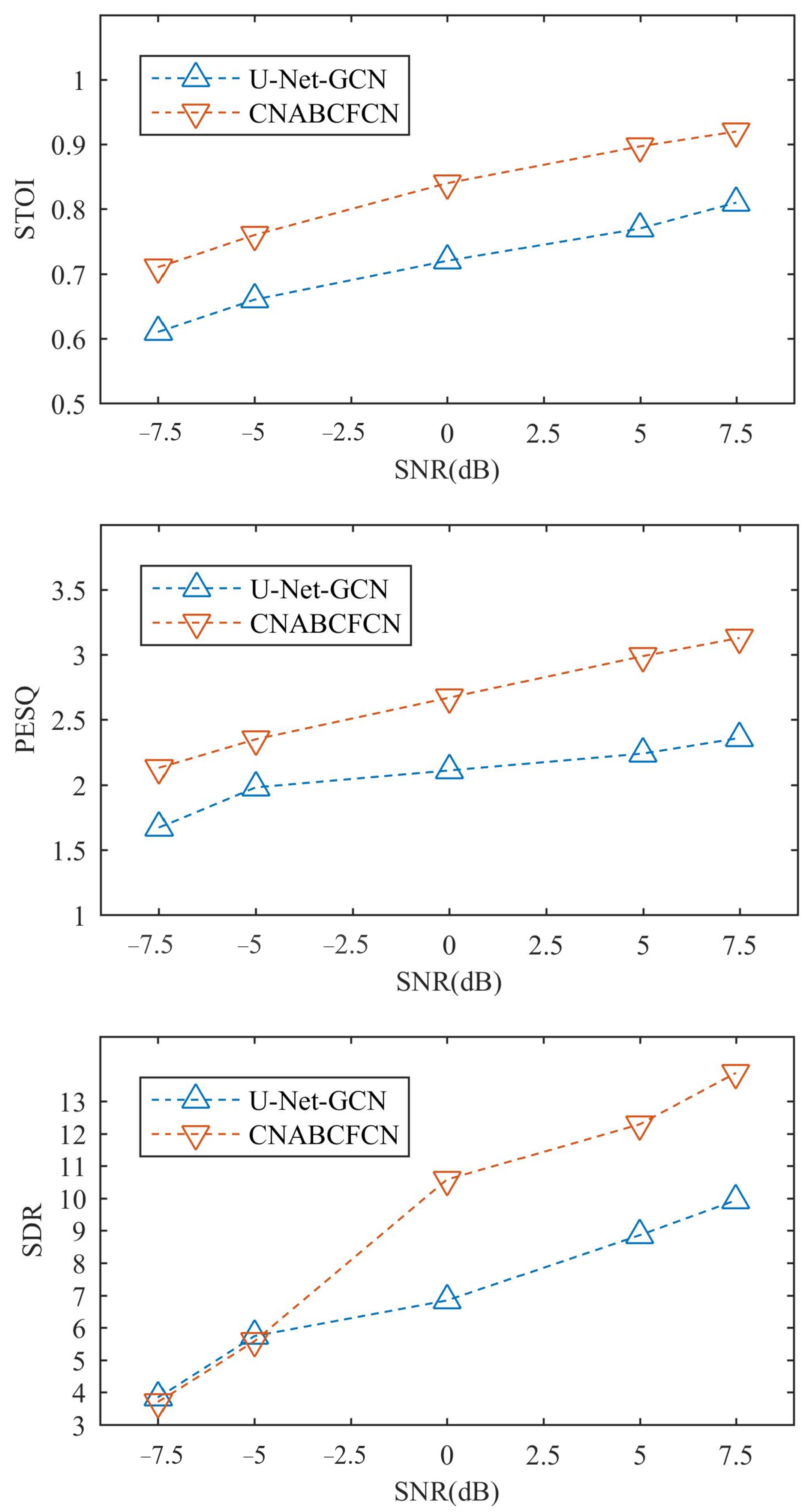
We report the in STOI, PESQ, and SDR results of both U-Net-GCN and CNABCFCN at different SNRs in Figure 9. The metrics for both networks improved as the SNR increased. However, the proposed model outperformed U-Net-GCN, as demonstrated by, for example, the gains of 0.12, 0.56, and 3.74 in STOI, PESQ, and SDR, respectively, achieved by CNABCFCN over U-Net-GCN when SNR = 0 dB (as seen in Table 8).
We compared the proposed CNABFCN model with the following dual-channel models in Scenario III to demonstrate its superior performance:
  • DNN [31,32], a vector-to-vector regression method that employs fully connected layers to perform speech enhancement.
  • TNN [33], a tensor-to-vector regression method used for multichannel speech enhancement.
  • BC-SE [34], a dual-microphone speech enhancement algorithm that employs a bone conduction sensor to map noisy speech at low frequencies.
Table 9 presents the PESQ results of different networks. The PESQ results of DNN and TNN were averaged at input SNRs of 10 dB to 20 dB, while the results of BC-SE and CNABCFCN were computed at input SNRs of 5 dB to 15 dB. Despite the lower SNRs, the proposed network outperformed both DNN and TNN. Additionally, the proposed model outperformed BC-SE by 0.96, as shown in the table.

5. Conclusions

In this study, we propose a novel complex time-domain process and design a complex neural network structure called CNABCFCN for dual-channel end-to-end speech enhancement. We leveraged the Hilbert transform to generate complex time-domain waveforms and incorporated complex operation rules to develop a network consisting of a CNAB and a CFCN. The CNAB takes dual-channel complex inputs to produce a complex single-channel output, while the CFCN is cascaded to obtain the final enhancement. Furthermore, we used a new loss function called SI-SDR, which considers both the real and imaginary parts of the speech waveform to balance speech quality. We evaluated the proposed network under different scenarios and demonstrated its versatility and effectiveness. Our results show that adding imaginary information improves denoising performance, and the proposed network outperformed existing methods in all scenarios based on both objective and subjective evaluations. Future research should explore extensions to more than two channels.

Author Contributions

Conceptualization, J.P. and H.L. (Hongqing Liu); Methodology, J.P.; Software, H.L. (Hongcheng Li) and T.J.; Validation, H.L. (Hongcheng Li) and H.W.; Formal analysis, J.P.; Investigation, H.W.; Resources, X.L.; Data curation, T.J. and X.L.; Writing—review & editing, H.L. (Hongqing Liu); Supervision, L.L.; Project administration, L.L.; Funding acquisition, H.L. (Hongqing Liu). All authors have read and agreed to the published version of the manuscript.

Funding

This study was supported by State Key Laboratory of Intelligent Vehicle Safety Technology (NVHSKL-202205) and Natural Science Foundation of Chongqing, China (No. cstc2021jcyj-bshX0206).

Institutional Review Board Statement

This study did not require ethical approval.

Informed Consent Statement

This study did not invlove human test.

Data Availability Statement

There are no data that need to be shared since author use public data.

Conflicts of Interest

The authors declare no conflict of interest.

References

  1. Sainath, T.N.; Weiss, R.J.; Wilson, K.W.; Li, B.; Narayanan, A.; Variani, E.; Bacchiani, M.; Shafran, I.; Senior, A.; Chin, K.; et al. Multichannel signal processing with deep neural networks for automatic speech recognition. IEEE/ACM Trans. Audio Speech Lang. Process. 2017, 25, 965–979. [Google Scholar] [CrossRef]
  2. Loizou, P.C. Speech Enhancement: Theory and Practice; CRC Press: Boca Raton, FL, USA, 2007. [Google Scholar]
  3. Parchami, M.; Zhu, W.P.; Champagne, B.; Plourde, E. Recent developments in speech enhancement in the short-time Fourier transform domain. IEEE Circuits Syst. Mag. 2016, 16, 45–77. [Google Scholar] [CrossRef]
  4. Tan, K.; Wang, D. A Convolutional Recurrent Neural Network for Real-Time Speech Enhancement. In Proceedings of the Interspeech, Hyderabad, India, 2–6 September 2018; pp. 3229–3233. [Google Scholar]
  5. Wang, H.; Wang, D. Time-frequency loss for CNN based speech super-resolution. In Proceedings of the ICASSP 2020—2020 IEEE International Conference on Acoustics, Speech and Signal Processing (ICASSP), Barcelona, Spain, 4–8 May 2020; pp. 861–865. [Google Scholar]
  6. Pandey, A.; Wang, D. A new framework for CNN-based speech enhancement in the time domain. IEEE/ACM Trans. Audio Speech Lang. Process. 2019, 27, 1179–1188. [Google Scholar] [CrossRef] [PubMed]
  7. Fu, S.W.; Tsao, Y.; Lu, X.; Kawai, H. Raw waveform-based speech enhancement by fully convolutional networks. In Proceedings of the 2017 Asia-Pacific Signal and Information Processing Association Annual Summit and Conference (APSIPA ASC), Kuala Lumpur, Malaysia, 12–15 December 2017; pp. 006–012. [Google Scholar]
  8. Hu, Y.; Liu, Y.; Lv, S.; Xing, M.; Zhang, S.; Fu, Y.; Wu, J.; Zhang, B.; Xie, L. DCCRN: Deep complex convolution recurrent network for phase-aware speech enhancement. arXiv 2020, arXiv:2008.00264. [Google Scholar]
  9. Tawara, N.; Kobayashi, T.; Ogawa, T. Multi-Channel Speech Enhancement Using Time-Domain Convolutional Denoising Autoencoder. In Proceedings of the INTERSPEECH, Graz, Austria, 15–19 September 2019; pp. 86–90. [Google Scholar]
  10. Van Veen, B.D.; Buckley, K.M. Beamforming: A versatile approach to spatial filtering. IEEE ASSP Mag. 1988, 5, 4–24. [Google Scholar] [CrossRef] [PubMed]
  11. Hoshuyama, O.; Sugiyama, A.; Hirano, A. A robust adaptive beamformer for microphone arrays with a blocking matrix using constrained adaptive filters. IEEE Trans. Signal Process. 1999, 47, 2677–2684. [Google Scholar] [CrossRef]
  12. Pfeifenberger, L.; Zohrer, M.; Pernkopf, F. Eigenvector-Based Speech Mask Estimation for Multi-Channel Speech Enhancement. IEEE Trans. Audio Speech Lang. Process. 2019, 27, 2162–2172. [Google Scholar] [CrossRef]
  13. Pfeifenberger, L.; Pernkopf, F. Blind source extraction based on a direction-dependent a-priori SNR. In Proceedings of the Fifteenth Annual Conference of the International Speech Communication Association, Singapore, 14–18 September 2014. [Google Scholar]
  14. Lu, X.; Tsao, Y.; Matsuda, S.; Hori, C. Speech enhancement based on deep denoising autoencoder. In Proceedings of the Interspeech, Lyon, France, 25–29 August 2013; Volume 2013, pp. 436–440. [Google Scholar]
  15. Wang, Z.Q.; Wang, P.; Wang, D. Complex spectral mapping for single-and multi-channel speech enhancement and robust ASR. IEEE/ACM Trans. Audio Speech Lang. Process. 2020, 28, 1778–1787. [Google Scholar] [CrossRef] [PubMed]
  16. Li, B.; Sainath, T.N.; Weiss, R.J.; Wilson, K.W.; Bacchiani, M. Neural network adaptive beamforming for robust multichannel speech recognition 2016. In Proceedings of the Interspeech, San Francisco, CA, USA, 8–12 September 2016; Volume 2016, pp. 1976–1980. [Google Scholar]
  17. Luo, Y.; Mesgarani, N. Implicit filter-and-sum network for multi-channel speech separation. arXiv 2020, arXiv:2011.08401. [Google Scholar]
  18. Hoshen, Y.; Weiss, R.J.; Wilson, K.W. Speech acoustic modeling from raw multichannel waveforms. In Proceedings of the IEEE International Conference on Acoustics, Speech and Signal Processing (ICASSP), South Brisbane, QLD, Australia, 19–24 April 2015; pp. 4624–4628. [Google Scholar]
  19. Sainath, T.N.; Weiss, R.J.; Wilson, K.W.; Narayanan, A.; Bacchiani, M.; Senior, A. Speaker location and microphone spacing invariant acoustic modeling from raw multichannel waveforms. In Proceedings of the IEEE Workshop on Automatic Speech Recognition and Understanding (ASRU), Scottsdale, AZ, USA, 13–17 December 2015; pp. 30–36. [Google Scholar]
  20. Kolbæk, M.; Tan, Z.H.; Jensen, S.H.; Jensen, J. On loss functions for supervised monaural time-domain speech enhancement. IEEE/ACM Trans. Audio Speech Lang. Process. 2020, 28, 825–838. [Google Scholar] [CrossRef] [Green Version]
  21. Santurkar, S.; Tsipras, D.; Ilyas, A.; Madry, A. How does batch normalization help optimization? arXiv 2018, arXiv:1805.11604. [Google Scholar]
  22. Luo, Y.; Mesgarani, N. Conv-tasnet: Surpassing ideal time–frequency magnitude masking for speech separation. IEEE/ACM Trans. Audio Speech Lang. Process. 2019, 27, 1256–1266. [Google Scholar] [CrossRef] [PubMed] [Green Version]
  23. Reddy, C.K.; Gopal, V.; Cutler, R.; Beyrami, E.; Cheng, R.; Dubey, H.; Matusevych, S.; Aichner, R.; Aazami, A.; Braun, S.; et al. The interspeech 2020 deep noise suppression challenge: Datasets, subjective testing framework, and challenge results. arXiv 2020, arXiv:2005.13981. [Google Scholar]
  24. Allen, J.B.; Berkley, D.A. Image method for efficiently simulating small-room acoustics. J. Acoust. Soc. Am. 1979, 65, 943–950. [Google Scholar] [CrossRef]
  25. Taal, C.H.; Hendriks, R.C.; Heusdens, R.; Jensen, J. An algorithm for intelligibility prediction of time–frequency weighted noisy speech. IEEE/ACM Trans. Audio Speech Lang. Process. 2011, 19, 2125–2136. [Google Scholar] [CrossRef]
  26. Rix, A.W.; Beerends, J.G.; Hollier, M.P.; Hekstra, A.P. Perceptual evaluation of speech quality (PESQ)—A new method for speech quality assessment of telephone networks and codecs. In Proceedings of the IEEE International Conference on Acoustics, Speech, and Signal Processing. Proceedings (Cat. No. 01CH37221), Salt Lake City, UT, USA,, 7–11 May 2001; Volume 2, pp. 749–752. [Google Scholar]
  27. Le, X.; Chen, H.; Chen, K.; Lu, J. DPCRN: Dual-path convolution recurrent network for single channel speech enhancement. arXiv 2021, arXiv:2107.05429. [Google Scholar]
  28. Wan, L.; Liu, H.; Zhou, Y.; Ji, J. Multi-Loss Convolutional Network with Time-Frequency Attention for Speech Enhancement. arXiv 2023, arXiv:2306.08956. [Google Scholar]
  29. Tan, K.; Zhang, X.; Wang, D. Real-time speech enhancement using an efficient convolutional recurrent network for dual-microphone mobile phones in close-talk scenarios. In Proceedings of the ICASSP 2019—IEEE International Conference on Acoustics, Speech and Signal Processing (ICASSP), Brighton, UK, 12–17 May 2019; pp. 5751–5755. [Google Scholar]
  30. Tzirakis, P.; Kumar, A.; Donley, J. Multi-Channel Speech Enhancement Using Graph Neural Networks. In Proceedings of the ICASSP 2021—IEEE International Conference on Acoustics, Speech and Signal Processing (ICASSP), Toronto, ON, Canada, 6–11 June 2021; pp. 3415–3419. [Google Scholar]
  31. Xu, Y.; Du, J.; Dai, L.R.; Lee, C.H. A Regression Approach to Speech Enhancement Based on Deep Neural Networks. IEEE/ACM Trans. Audio Speech Lang. Process. 2015, 23, 7–19. [Google Scholar] [CrossRef]
  32. Wang, Q.; Wang, S.; Ge, F.; Han, C.W.; Lee, J.; Guo, L.; Lee, C.H. Two-stage enhancement of noisy and reverberant microphone array speech for automatic speech recognition systems trained with only clean speech. In Proceedings of the International Symposium on Chinese Spoken Language Processing (ISCSLP), Taipei, Taiwan, 26–29 November 2018; pp. 21–25. [Google Scholar]
  33. Qi, J.; Hu, H.; Wang, Y.; Yang, C.H.H.; Siniscalchi, S.M.; Lee, C.H. Tensor-to-vector regression for multi-channel speech enhancement based on tensor-train network. In Proceedings of the ICASSP 2020—IEEE International Conference on Acoustics, Speech and Signal Processing (ICASSP), Barcelona, Spain, 4–8 May 2020; pp. 7504–7508. [Google Scholar]
  34. Zhou, Y.; Chen, Y.; Ma, Y.; Liu, H. A Real-Time Dual-Microphone Speech Enhancement Algorithm Assisted by Bone Conduction Sensor. Sensors 2020, 20, 5050. [Google Scholar] [CrossRef]
Figure 1. CNABCFCN network.
Applsci 13 07698 g001
Figure 2. Complex LSTM.
Applsci 13 07698 g002
Figure 3. CFCN structure.
Applsci 13 07698 g003
Figure 4. Experimental configuration of a single target sound source. The target source is the position marked by the red box, and the noise source is distributed from 0 to 90 (Scenario I).
Applsci 13 07698 g004
Figure 5. Experimental configuration of regional target sound sources. The position of the target sound source is evenly distributed between −45 and 45 . Each target sound source may be affected by noise distributed from −90 to 90 (Scenario II).
Applsci 13 07698 g005
Figure 6. Frame structure of 1D Conv. The configuration in 1 × 1 Conv is kernel size and stride. The internal configurations of 1D dilated Conv are kernel size, stride, padding, and dilation.
Applsci 13 07698 g006
Figure 7. NABFCN structure.
Applsci 13 07698 g007
Figure 8. Spectrograms of noisy, clean, and enhanced speech signals at SNR = 5 dB.
Applsci 13 07698 g008
Figure 9. STOI, PESQ, and SDR values of different methods at different SNRs (Scenario III).
Applsci 13 07698 g009
Table 1. CNAB model, where B denotes the batch size and the format of hyperparameters is the size of the input and output channels of the LSTM.
Layer NameInput SizeHyperparameters
complex input(B, 2, 16,000), (B, 2, 16,000)-
complex shared-LSTM(B, 2, 100, 160)(160, 512)
complex split-LSTM(B, 2, 512)(512, 256)
complex linear(B, 2, 256)(256, 25)
Table 2. CFCN configuration, where B is the batch size and L is the length of the feature map. The format of hyperparameters for the convolutional network is the dimensions of the input and output, the size of the convolutional kernel, and the step size of stride.
Layer NameInput SizeHyperparameters
complex input(B, 2, 16,000)---
1D Conv(B, 16,000) × 2(1, 256), 40, 20
LayerNorm(B, 2, 256, L)BatchNorm2d
complex 1 × 1 Conv(B, 2, 256, L)(1, 1), (5, 2), (2, 1)
partial complex 1D Conv
1 × 1 Conv(B, 256, L)(256, 512), 1, 1
Table 3. Number of complex 1D Conv in CFCN and its corresponding SI-SDRs.
Numbers036912
SI-SDR−17.823−18.296−8.825−8.724−8.834
Table 4. NAB model, where B represents the batch size and the format of hyperparameters is the size of the input and output channels of LSTM.
Layer NameInput SizeHyperparameters
input(B, 16,000), (B, 16,000)
shared-LSTM(B, 100, 160)(160, 512)
split-LSTM(B, 512)(512, 256)
linear(B, 256)(256, 26)
Table 5. PESQ and STOI of CNABCFCN and NABFCN (Scenario I).
ModelMetricsSNR
−5 dB0 dB5 dB10 dB20 dB
NABFCNPESQ2.652.973.213.423.74
STOI87.4492.1494.9896.7798.62
CNABCFCNPESQ2.753.073.323.523.81
STOI89.2293.2995.7497.2798.81
Table 6. PESQ and STOI of CNABCFCN and NABFCN (Scenario II).
ModelMetricsSNR
−5 dB0 dB5 dB10 dB20 dB
NABFCNPESQ2.522.853.163.343.64
STOI85.9489.9593.2795.6897.52
CNABCFCNPESQ2.662.973.243.453.74
STOI87.5492.4095.2496.9998.70
Table 7. PESQ and STOI of different networks on the DNS dataset (Scenario I).
ModelMicsPara (M)PESQSTOI
−5 dB0 dB5 dB−5 dB0 dB5 dB
noisy--1.371.671.9866.9175.5783.26
C-TasNet15.12.392.753.0281.3888.9593.17
DCCRN15.32.232.632.9580.7989.0292.58
DPCRN10.82.362.672.9175.0881.6086.28
MNTFA10.232.422.723.0275.6481.9786.78
CRN-i20.081.561.892.2869.5178.6886.27
CRN-ii217.61.611.962.3371.0679.8587.15
CNABCFCN29.22.753.073.3289.2293.2995.74
Table 8. STOI, PESQ, and SDR on the DNS dataset (Scenario III).
Model−7.5 dB−5 dB0 dB5 dB7.5 dB
STOIPESQSDRSTOIPESQSDRSTOIPESQSDRSTOIPESQSDRSTOIPESQSDR
noisy0.551.46−7.510.601.54−5.060.711.871.570.802.234.810.842.417.22
U-Net-GCN0.601.673.840.661.985.740.722.116.840.772.248.860.812.369.94
CNABCFCN0.712.143.700.762.335.580.842.6710.580.892.9912.290.923.1313.88
Table 9. PESQ of different dual-channel networks (Scenario III).
ModelMicsPara (M)PESQ
DNN2333.00
DNN-SVD252.93
TNN20.62.75
TNN252.96
BC-SE2--2.24
CNABCFCN29.23.20
Disclaimer/Publisher’s Note: The statements, opinions and data contained in all publications are solely those of the individual author(s) and contributor(s) and not of MDPI and/or the editor(s). MDPI and/or the editor(s) disclaim responsibility for any injury to people or property resulting from any ideas, methods, instructions or products referred to in the content.