Article

Research on Tracking Control of Urban Rail Trains Based on Improved Disturbance Observer

1
School of Electrical and Automation Engineering, East China Jiaotong University, Nanchang 330013, China
2
Key Laboratory of Advanced Control & Optimization of Jiangxi Province, East China Jiaotong University, Nanchang 330013, China
3
State Key Laboratory of Performance Monitoring Protecting of Rail Transit Infrastructure, East China Jiaotong University, Nanchang 330013, China
*
Author to whom correspondence should be addressed.
Appl. Sci. 2023, 13(13), 7403; https://doi.org/10.3390/app13137403
Submission received: 25 May 2023 / Revised: 20 June 2023 / Accepted: 21 June 2023 / Published: 22 June 2023
(This article belongs to the Section Applied Industrial Technologies)

Abstract

:
Urban rail transit trains operate in a complex and changing environment susceptible to uncertainties such as unknown disturbances or actuator faults. In order to ensure that the automatic train control (ATC) system can operate safely and control accurately even when the train is affected by uncertainties, the train is first subjected to force analysis, and a multiple point-mass model for the urban rail trains (URTs) is established. Secondly, an improved disturbance observer is proposed to estimate and attenuate the unknown disturbance online. The stability of the URTs system under the improved disturbance observer-based control (IDOBC) is demonstrated based on the linear matrix inequality and Lyapunov theorem. Finally, the Simulink platform is used to verify the target curves obtained after data optimization of the certain Nanchang Metro line for case verification. Compared to the traditional disturbance observer-based control (TDOBC) method, the train tracking error converges to near the zero region faster after being subjected to an external disturbance, and the mean absolute error (MAE) metric is smaller throughout the whole operation. The control strategy proposed in this paper has a more desirable control effect and can ensure the safer and more stable operation of the URTs.

1. Introduction

In the past few years, with the increasing urbanization trend, an increasing number of people in China have flocked to cities, leading to a heightened significance of urban public transportation in facilitating people’s mobility [1]. In order to relieve the pressure of traffic transportation in big cities, urban rail trains (URTs) have been developed rapidly. Therefore, the train control technology that can achieve high efficiency, high density, and high safety in urban rail system has emerged as a popular subject of research [2]. In the automatic train control (ATC) system, the automatic train operation (ATO) is responsible for providing safety limits and control references for traction and braking equipment, which can guarantee the URTs’ operational safety, punctuality, and enable autonomous driving [3,4].
Since the ATO for URTs plays a pivotal role in achieving driverless operation, many scholars have proposed a lot of efficient algorithms. Literature [5] discards the train model information and offline speed profiles, intelligent algorithms based on hybrid expert systems and reinforcement learning are designed to achieve operational errors that meet the requirements. To follow the schedule/headway adherence, an adaptive optimal control algorithm was proposed in [6] to obtain tracking control with low energy consumption. In [7], a heuristic algorithm is used to achieve the motion pattern of the train with minimum energy consumption to achieve energy-efficient cooperative control of multiple trains. Literature [8] solves the nonlinear optimization problem of the train presence by using punctuality as a penalty factor and minimum traction energy as an objective using a heuristic evolutionary algorithm. In [9], a PID controller is implemented to enhance the resilience and precision in tracking of the subway train and use neural networks to adjust the PID parameter gains adaptively. In the above mention literature, the researchers analyzed the motion state of URTs by considering the URTs as a single point-mass model to establish the kinematic equations. The single point-mass model has the advantage of real-time and accuracy in simulating the operation effect of the UTRs and has a high level of computational efficiency. However, the single point-mass model neglects the interconnected forces among the carriages, which reduces the control accuracy during the force analysis, and the control effect under the operating platform is also not satisfactory [10]. Therefore, in order to improve the control accuracy of the URTs, this paper considers the coupling forces to establish a multiple point-mass model, which better corresponds to the practical operation of URTs.
The URTs operate most of the time in tunnels, where the operating environment is relatively stable and less affected by uncertain disturbances. Nevertheless, during the actual operation, it remains susceptible to unpredictable external disturbances caused by variations in environmental factors. Especially in the moment of operation from the tunnel to the ground environment, the resistance suffered by the URTs will change significantly. In addition, when the URTs operate on the elevated road, the impact of some uncertainties, such as wind gusts of different levels or disturbance from trains running on adjacent tracks, will be significantly increased. These uncertain external unknown disturbances will seriously affect the tracking performance of the URTs and may also pose a threat to the safe and stable operation of the URTs. In order to improve the robustness of the high-speed train system, a speed prediction control method based on an improved echo state network was proposed in [11]. In [12], a H robust output feedback controller with uncertain drag coefficients was designed to suppress external disturbances. This method may be too conservative in practical application engineering to eliminate disturbances at a fast rate. In [13], an adaptive sliding mode controller was designed to ensure stable tracking of the train under external disturbances and to solve the singularity issue caused by the terminal sliding mode control. The design of the output feedback controller using the linear decoupling method was present in [14] to solve the tracking control under uncertainty and disturbance of train parameters. Although the mentioned above anti-disturbance methods have satisfactory results in terms of system control accuracy, direct disturbance suppression is not considered in the controller design process, and most of them are used to attenuate disturbances by indirect means. In such a case, it is difficult for these controllers to respond quickly when strong disturbances are present.
The disturbance observer-based control (DOBC) approach is well recognized for improving the robustness of the system and provides a way to proactively handle unknown disturbances [15]. The DOBC method has been widely used in various fields. In [16], sliding-mode manifolds satisfying finite-time convergence are designed for second-order nonlinear systems, and a nonlinear DOBC strategy is proposed and theoretically verified in the fields of robotic arms and magnetic levitation systems. In [17], for the trajectory tracking problem of a quadrotor system under gusty wind disturbance, a disturbance observer based on LQR (linear-quadratic regulator) and KF (Kalman filter) is proposed, which substantially minimizes the error in position tracking. In [18], the dynamic performance of the permanent magnet synchronous motor drive system is significantly improved by introducing a disturbance observer to eliminate load disturbances. In high-speed train cruise control, the disturbance observer is used to estimate unknown perturbations to improve system robustness, but only if the disturbance model is known [19]. The nonlinear disturbance observer is introduced into the maglev system to ensure the stable suspension of the train, but the train model is based on the single point-mass, and the accuracy needs to be improved [20]. In [21], a sliding mode disturbance observer is proposed for the uncertainty in the braking control of the URTs, which has excellent compensation ability but does not give experimental results at the operation switching points of the train.
Based on the above analysis, this paper investigates an improved disturbance observer-based train tracking control method. The method is based on the multiple point-mass model for URTs, and introduces the disturbance observer to estimate the unknown disturbances to the train during operation and then feeds the estimated values back into the system input to achieve the purpose of attenuating the disturbances. The introduction of the disturbance observer not only improves the robustness of the train system but also ensures that the URTs can quickly track the target curves. In addition, rigorous reasoning is given for the stability of the closed-loop system for the URTs. The evaluation of the control accuracy and safety of the system under the two different control methods is given through comparative simulation experiments with the traditional disturbance observer-based control (TDOBC) method. The major contributions are summarized as follows.
(1)
In this paper, to more accurately describe the motion state of the URTs and improve the control accuracy, consider the coupling force between carriages to establish the multiple point-mass model. An expression for the state space form with partial actuator failure is also given.
(2)
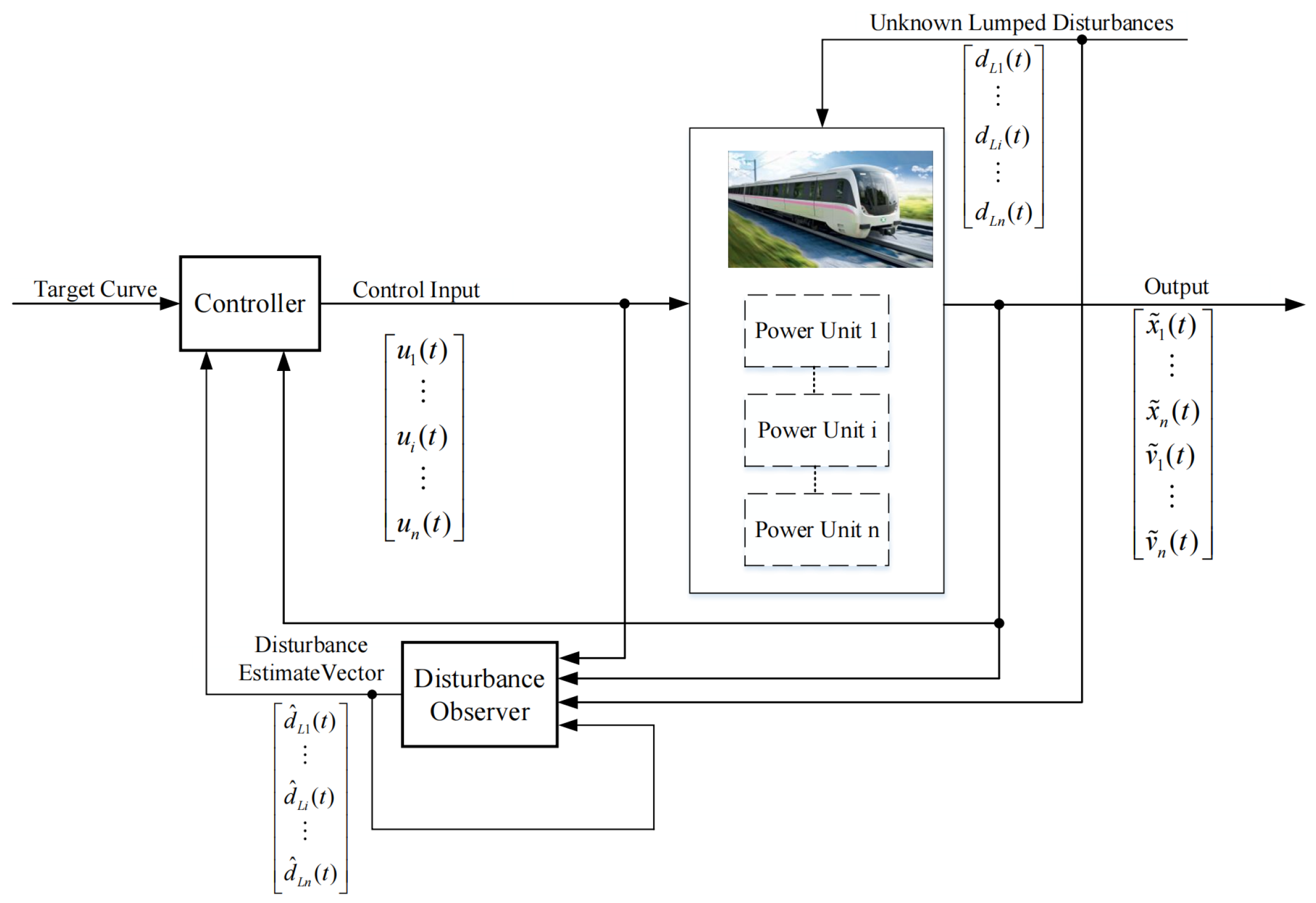
In order to enhance the anti-disturbance ability of the URTs system, an improved disturbance observer is proposed for unknown external disturbances to estimate and attenuate the unknown disturbances online. The proposed disturbance observer-based controller has high control accuracy and anti-disturbance capability.
(3)
The proposed disturbance observer in this paper does not require a priori knowledge of unknown disturbances and can estimate attenuation for more types of disturbances. The strict condition that the rate of change of disturbance is equal to zero is also removed, which aligns better with the actual scenario of URTs operation.
The rest of this paper is organized as follows. Section 2 analyzes the coupling force and running resistance to which the URTs is subjected and establishes a multiple point-mass model. In Section 3, an improved disturbance observer is designed, and proof of stability under the IDOBC method is given. Section 4 gives the simulation validation and statistical analysis. Some conclusions are provided in Section 5. The naming of the symbols is summarized in Table 1.

2. Problem Statement

In this section, a multiple point-mass model for the URTs containing unknown disturbance is developed to characterize the train operation process. Specifically, the in-train force caused by the coupler of the URTs is described, and the running resistance of the operation process is analyzed. Finally, the error dynamics equations for the linearization of the URTs system are given, and the matrix form under partial actuator failure is considered.

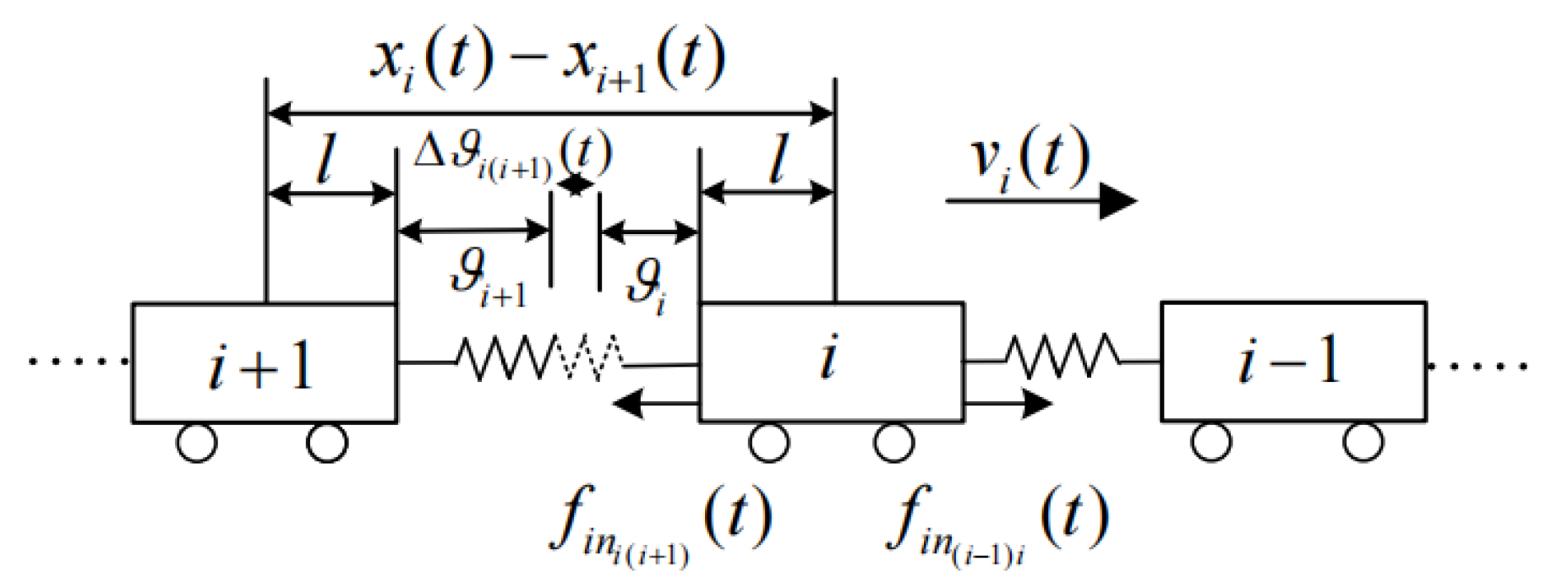
2.1. The In-Train Force and Running Resistance of the URTs

The two adjacent carriages of URTs are connected by a complex coupler, which plays a vital role in preventing collisions between carriages and absorbing longitudinal impact forces [22]. Besides, the couplers are subjected to excessive compression and tension, which leads to irreversible deformation and seriously threatens the safe operation of the URTs. Therefore, the consideration of the train coupling force holds tremendous significance. The simplified coupler of the connection between adjacent carriages is shown in Figure 1.
The internal structure and working principle of the couplers device are very complex. When analyzing the in-train force of the URTs, the connection device between the carriages can be simplified to a “spring” system, and the coupling forces between the ith carriage and the i + 1 th carriage can be expressed as
f i n i ( i + 1 ) ( t ) = κ Δ ϑ i ( i + 1 ) ( t )
where κ denotes the elastic coefficient of the coupler. According to the direction of the URTs operation shown in Figure 1, Δ ϑ i ( i + 1 ) ( t ) can be represented as
Δ ϑ i ( i + 1 ) ( t ) = x i ( t ) x i + 1 ( t ) S
where S = 2 l + ϑ i + ϑ i + 1 is a constant.
Based on Newton’s law of mechanics, the force analysis of the ith carriage is carried out.
m i v ˙ i ( t ) = u i ( t ) f i ( t ) f i n i ( i + 1 ) ( t ) + f i n ( i 1 ) i ( t )
where m i , v ˙ i ( t ) , and u i ( t ) denote the mass, control input, and acceleration of the ith carriage, respectively. f i ( t ) denotes the running resistance of the ith carriage, including basic resistance, additional resistance, and unknown external disturbance, which can be described as
f i ( t ) = a i + b i v i ( t ) + c i v i 2 ( t ) + f a i ( t ) + O i ( · )
where a i , b i , and c i denote the Davis coefficients of the ith carriage. The drag coefficients vary from different train types and are generally derived from experimental tests in wind tunnels. a i + b i v i ( t ) represents the rolling mechanical resistance between the wheels and rails, and c i v i 2 ( t ) represents the aerodynamic resistance. O i ( · ) is the unknown external disturbance to which the URTs subject and is highly influenced by operation environmental factors. f a i ( t ) denotes additional resistance, usually determined by the running track line, which can be described as
f a i ( t ) = d c + d r + d t
where d c = 10.5 α m i g / ( 10 3 l r ) , d r = m i g sin ( θ ) , and d t = 1.3 × 10 4 l s m i g / 10 3 represent the curve resistance, ramp resistance, and tunnel resistance, respectively [23]. l r , α , θ , and l s are curve length, curve center angle, slope angle, and tunnel length, respectively.

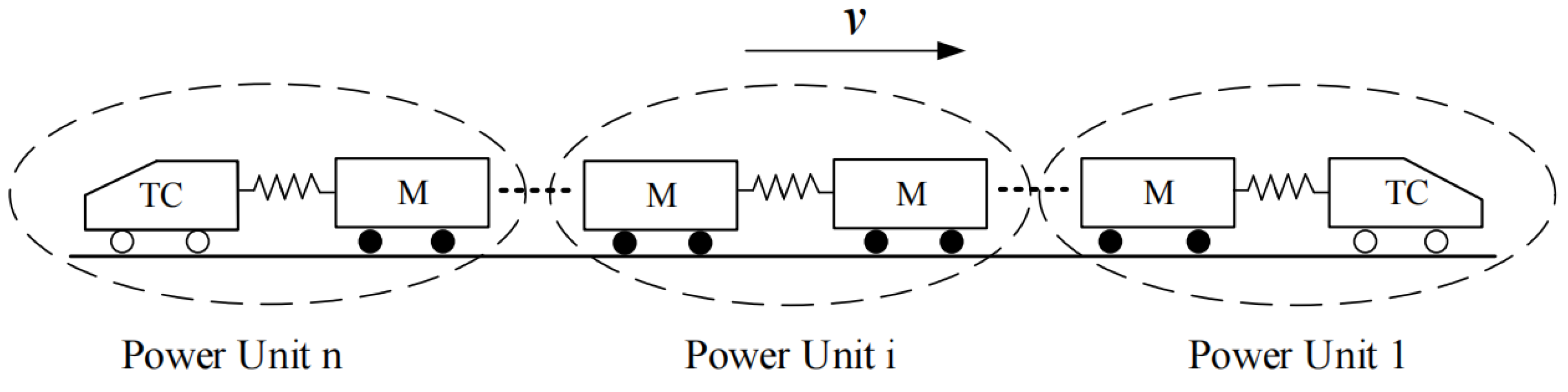
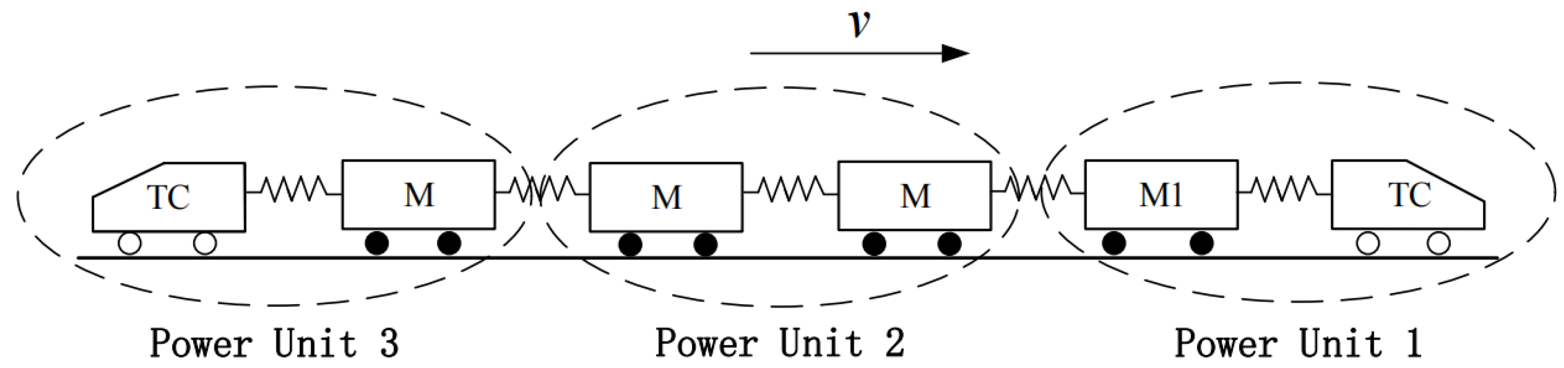
2.2. The Multiple Point-Mass Model of the URTs

The URTs is a decentralized power type consisting of motor carriages and trailers. The motor carriage provides power and braking force, and the trailer only provides the braking force. Typically, the URTs is grouped as shown in Figure 2, where the hollow wheels represent trailers and the solid wheels represent motor carriages.
The braking and traction system of the URTs is composed of several relatively independent carriages. The modeling process treats the adjacent carriages as one power unit. The advantage of this approach is that it not only reduces the computational complexity of the control process but also takes into account the in-train forces between adjacent carriages [24]. In this way, the URTs containing 2 n carriages are uniformly divided into n power units, each providing control forces. Considering the URTs with n power units, combined with the coupling forces between adjacent carriages and running resistance, the multiple point-mass dynamics equation of the URTs can be written as
x ˙ i ( t ) = v i ( t ) , i = 1 , 2 , , n m 1 v ˙ 1 ( t ) = u 1 ( t ) f i n 12 ( t ) f 1 ( t ) = u 1 ( t ) κ x 1 ( t ) x 2 ( t ) S m 1 a 1 m 1 b 1 v 1 ( t ) ( i = 1 n m i ) c 1 v 1 ( t ) 2 + d L 1 ( t ) m i v ˙ i ( t ) = u i ( t ) f i n i ( i + 1 ) ( t ) + f i n ( i 1 ) i ( t ) f i ( t ) = u i ( t ) κ x i ( t ) x i + 1 ( t ) S + κ x i 1 ( t ) x i ( t ) S m i a i m i b i v i ( t ) + d L i ( t ) m n v ˙ n ( t ) = u n ( t ) + f i n ( n 1 ) n ( t ) f n ( t ) = u n ( t ) + κ x n 1 ( t ) x n ( t ) S m n a n m n b n v n ( t ) + d L n ( t )
where d L i ( t ) denotes the unknown lumped disturbance consisting of the additional resistance f a i ( t ) and the unknown external disturbance O i ( · ) . According to the kinematic characteristics of the URTs, this paper considers that the aerodynamic resistance is mainly concentrated on the first power unit in the running direction, and the mechanical rolling mechanical resistance acts on all the power units.
Assume the first power unit has desired speed and desired position
x ˙ r ( t ) = v r
Without loss of generality, it is assumed that each power unit of the URTs in the equilibrium satisfies the desired velocity v 1 e ( t ) = v 2 e ( t ) = = v n e ( t ) = v r and acceleration v ˙ 1 e ( t ) = v ˙ 2 e ( t ) = = v ˙ n e ( t ) = 0 . Then, substituting the above assumptions into (6), the position (8) and control inputs (9) of the power unit at equilibrium are obtained.
x i e ( t ) x i + 1 e ( t ) = S
u 1 e = m 1 a 1 + m 1 b 1 v r + ( i = 1 n m i ) c 1 v r 2 u i e = m i a i + m i b i v r , i = 2 , n
This means the power units maintain a stable operating distance when the URTs is in equilibrium. At this time, the couplers work in a relaxed state to ensure safe operation between the power units of the URTs. Define the position error variables, speed error variables, and control input error variables as x ˜ i ( t ) = x i ( t ) x i e ( t ) + S ( i 1 ) , v ˜ i ( t ) = v i ( t ) v i e ( t ) , and u ˜ i ( t ) = u i ( t ) u i e ( t ) . Using the same linearization principle as in reference [25], the linear error kinetic equations of the URTs in equilibrium can be written as
x ˜ ˙ i ( t ) = v ˜ i ( t ) , i = 1 , 2 , n m 1 v ˜ ˙ 1 ( t ) = u ˜ 1 ( t ) κ x ˜ 1 ( t ) x ˜ 2 ( t ) m 1 b 1 v ˜ 1 ( t ) 2 ( i = 1 n m i ) c 1 v r v ˜ 1 ( t ) + d L 1 ( t ) m i v ˜ ˙ i ( t ) = u ˜ i ( t ) κ x ˜ i ( t ) x ˜ i + 1 ( t ) + κ x ˜ i 1 ( t ) x ˜ i ( t ) m i b i v ˜ i ( t ) + d L i ( t ) , i = 1 , 2 , n 1 m n v ˜ ˙ n ( t ) = u ˜ n ( t ) + κ x ˜ n 1 ( t ) x ˜ n ( t ) m n b n v ˜ n ( t ) + d L n ( t )
Let X ( t ) = x ˜ 1 ( t ) , , x ˜ n ( t ) , v ˜ 1 ( t ) , , v ˜ n ( t ) T and U ( t ) = [ u ˜ 1 ( t ) , , u ˜ n ( t ) ] T be the new state variables and control inputs. The following dynamics equations in state space form are further obtained
X ˙ ( t ) = A X ( t ) + B U ( t ) + B d L
where A = 0 n × n I n × n A 21 A 22 , B = 0 n × n B 21 . More precise,
A 21 = κ m 1 κ m 1 0 0 κ m 2 2 κ m 2 κ m 2 0 0 0 2 κ m n 1 κ m n 1 0 0 κ m n κ m n ,
A 22 = b 1 2 ( i = 1 n m i ) c 1 v r / m 1 0 0 0 0 b 2 0 0 0 0 b n 1 0 0 0 0 b n
B 21 = d i a g 1 / m 1 , 1 / m 2 , , 1 / m n , d L ( t ) = [ d L 1 ( t ) , d L 2 ( t ) , , d L n ( t ) ] T .
Actuator faults are common during the operation of the URTs, which can also seriously affect the safe train operation. Therefore, it makes sense to consider actuator faults in the URTs. Combining (11) with actuator faults
X ˙ ( t ) = A X ( t ) + B ρ U ( t ) + B d L
where B ρ = B ρ . ρ = d i a g ρ 1 , ρ 2 , , ρ n indicates the actuator faults matrix. ρ i is the actuator health factor of the i th carriage. ρ i satisfies 0 < ρ i 1 . When ρ i = 1 , it means that the power unit is faultless.
Remark 1. 
The above modeling approach of treating two carriages as one power unit is well mature in the high-speed trains field [24,26]. Since the train formation and basic structure are similar to high-speed trains, it is reasonable to borrow the modeling approach from the above literature.
Remark 2. 
The ramp resistance, tunnel resistance, and curve resistance suffered by the URTs are all related to the fixed running route. In addition to that, the unknown external disturbances suffered cannot be infinite, so d L ( t ) is norm bounded.

3. Main Results

This section proposes an improved observer-based control scheme. Firstly, the disturbance observer is designed to estimate and attenuate the total uncertainty, including the additional resistance and the unknown disturbance. Then stability analysis is conducted on the proposed disturbance observer and control method. Figure 3 gives the block diagram of the URTs tracking control based on the proposed method.

3.1. The Improved Disturbance Observer Design

The nonlinear disturbance observer proposed in [20,27] is simple in structure, has few computations, and can obtain highly accurate estimates. Therefore, for the URTs system (12), the following improved state-space disturbance observer is proposed to estimate the complex unknown lumped disturbances.
d ^ L ( t ) = P ( t ) + L X ( t ) P ˙ ( t ) = L B P ( t ) L B L X ( t ) L A X ( t ) + B ρ U ( t ) c sgn ( e d ( t ) )
where d ^ L ( t ) is the estimate of the lumped disturbance d L ( t ) . L = [ L A , L B ] is the gain matrix of the observer to be designed. c sgn ( e d ( t ) ) is the observer error compensation term and c is a constant. P ( t ) is the state variable inside the observer.
Here, some mild assumptions are given to prove the stability of the disturbance observer system (13).
Assumption 1. 
A , B ρ is controllable.
Assumption 2. 
The lumped disturbance d L ( t ) to the URTs is not a slow time-varying disturbance, i.e., it satisfies d ˙ L ( t ) ε , where ε > 0 is an unknown constant.
The convergence of the improved disturbance observer is given by Theorem 1 below.
Theorem 1. 
The URTs system (12) is assumed to satisfy Assumptions 1 and 2. When the observer gain matrix L is chosen such that L B is Hurwitz, the disturbance estimate d ^ L ( t ) obtained from the observer (13) could track the unknown lumped disturbance d L ( t ) asymptotically.
(Proof of Theorem 1).
Define interference observer estimation error
e d ( t ) = d ^ L ( t ) d L ( t )
Combining the URTs system (12), the disturbance observer (13), and the estimation error (14), one has
e ˙ d ( t ) = d ^ L ˙ ( t ) d ˙ L ( t ) = P ˙ ( t ) + L X ˙ ( t ) d ˙ L ( t ) = L B d ^ L ( t ) d L ( t ) d ˙ L ( t ) c sgn ( e d ( t ) ) = L B e d ( t ) d ˙ L ( t ) c sgn ( e d ( t ) )
Since L B is Hurwitz, according to the form of the matrix B, then L B is also Hurwitz. Then it means that there exist positive symmetric matrices Φ and Q satisfying the following form
( L B ) T Φ + Φ ( L B ) T = Q
For (16), define the Lyapunov function V a ( t )
V a ( t ) = e d T ( t ) Φ e d ( t )
According to the state trajectory of (15), the derivative of V a is obtained
V ˙ a ( t ) = e ˙ d T ( t ) Φ e d ( t ) + e d T ( t ) Φ e ˙ d ( t ) = L B e d ( t ) d ˙ L ( t ) c sgn ( e d ( t ) ) T Φ e d ( t ) + e d T ( t ) Φ L B e d ( t ) d ˙ L ( t ) c sgn ( e d ( t ) ) = e d T ( t ) Q e d ( t ) 2 e d T ( t ) Φ d ˙ L ( t ) + c sgn ( e d ( t ) )
From Assumption 2, the derivative of the V ˙ a ( t ) satisfies
V ˙ a ( t ) σ min ( Q ) e d ( t ) 2 + 2 ( ε + c ) σ max ( Φ ) e d ( t ) ( 1 ϑ ) σ min ( Q ) e d ( t ) 2 , e d ( t ) 2 ( ε + c ) σ max ( Φ ) ϑ σ min ( Q )
where 0 < ϑ < 1 . It shows that when ε + c is used as the system input and e d ( t ) is used as the state, the estimation error of the observer is input-to-state stable [28]. □
Remark 3. 
The disturbance observer operates with only the internal state variable P and does not need to calculate the differentiation of the system state variable X ( t ) , which has the advantage of not causing noise amplification and is easy to implement in the practical URTs system.
Remark 4. 
In [20,27], it is assumed that the compound disturbance changes slowly, which is considered too strict in the actual engineering of the URTs. Maintaining a stable constant value is difficult due to the time-varying disturbances to which the URTs are subjected during operation, especially when the URTs travel on the ground, in environments with slopes and curves, where the external uncertainties have a greater impact on the trains. Therefore, this paper removes the condition that the disturbance is a slow time-varying perturbation, i.e., d ˙ L ( t ) 0 . Moreover, the proposed improved disturbance observer does not require a priori knowledge of the unknown disturbance model [19], which broadens the application of the disturbance observer.

3.2. Controller Design and Stability Proof Based on Improved Disturbance Observer

In order to compensate for the effects of unknown lumped disturbances and partial actuator faults, the control law can have the form as
U ( t ) = K X ( t ) ρ 1 d ^ L ( t )
where K is the controller gain matrix to be designed.
Bringing the control law (20) into the URTs system (12), combined with the disturbance observer estimation error as (15), yields the augmented system state space expression (21).
ξ ˙ ( t ) = M ¯ ξ ( t ) + N ¯ φ ( t )
with ξ T ( t ) = [ X T ( t ) , e d T ( t ) ] , φ ( t ) = d ˙ L ( t ) + c sgn ( e d ( t ) ) , M ¯ = A + B ρ K B 0 n × 2 n L B and N ¯ = 0 2 n × n I n .
Define the reference output of the augmentation system (21) as follows:
Z ( t ) = C 1 X ( t ) + C 2 e d ( t ) = C ¯ ξ ( t )
where C ¯ = [ C 1 , C 2 ] .
The stability of the closed-loop system consisting of the augmented system (21) and the reference output (22) is given by Theorem 2.
Theorem 2. 
Consider the augmentation system (21) and the reference output (22). For a given positive constant λ, if there exist matrices  H 1 > 0 , H 2 > 0 , and H 3  satisfying the matrix inequality shown as (23), then there exists a control law (20) based on an improved disturbance observer that ensures the closed-loop system is asymptotically stable and satisfies the  H  performance index  J = 0 τ Z T ( t ) Z ( t ) λ φ T ( t ) φ ( t ) d t .
Γ 1 + Γ 2 B 0 0 H 1 C 1 T Γ 3 H 2 0 C 2 T λ I 0 0 I 0 I < 0
where Γ 1 = S y m ( A H 1 ) , Γ 2 = S y m ( B ρ H 3 ) , and Γ 3 = S y m ( H 2 L B ) .
(Proof of Theorem 2).
Construct the candidate Lyapunov function V b .
V b ( t ) = X T ( t ) P 1 X ( t ) + e d T ( t ) P 2 e d ( t )
with P 1 > 0 , P 2 > 0 .
The derivative of the above Lyapunov function can be obtained by collation as (25).
V ˙ b ( t ) = X T ( t ) P 1 ( A + B ρ K ) + ( A + B ρ K ) T P 1 X ( t ) S y m X T ( t ) P 1 B e d ( t ) + e d T ( t ) P 2 φ ( t ) e d T ( t ) P 2 L B + ( L B ) T P 2 e d ( t )
According to (25) and the H performance index, one has
J = 0 τ Z T ( t ) Z ( t ) λ φ T ( t ) φ ( t ) + V ˙ b ( t ) d t V b ( t )
(26) could be further written as
J = 0 τ ψ T ( t ) Ξ ψ ( t ) d t V b ( t )
where ψ ( t ) = [ X T ( t ) e d T ( t ) φ T ( t ) ] T , Ξ = S y m P 1 ( A + B ρ K ) + C 1 T C 1 P 1 B + C 1 T C 2 0 S y m P 2 L B + C 2 T C 2 P 2 λ I .
Based on the non-negativity of the Lyapunov function (24), for J < 0 to hold, Ξ < 0 must satisfy. Applying the Schur complement and congruence transformations to the matrix inequality and defining H 1 = P 1 1 , H 2 = P 2 , and H 3 = K P 1 1 yields Ξ < 0 , which in turn yields J < 0 . That is, with zero initial condition and any d ˙ L ( t ) 0 , Z ( t ) 2 λ d ˙ L ( t ) 2 is always satisfied when τ . □
Remark 5. 
The URTs system estimates and attenuates the unknown lumped disturbances online under the IDOBC strategy. The baseline feedback controller approach near nominal control performance in the absence of disturbances. If subjected to external disturbances, the disturbance observer is activated for disturbance compensation and attenuation, providing robustness to disturbances without involving too much control energy.
Remark 6. 
A switching function in the observer (13) causes jittering phenomena, adversely affecting the traction and braking equipment of the UTRs. Here, we use the saturation function sat ( e d ( t ) ) instead of the switching function sgn ( e d ( t ) ) in the observer, i.e.,
sat ( e d ( t ) ) = e d ( t ) δ , i f e d ( t ) δ ; sgn ( e d ( t ) ) , i f e d ( t ) > δ .
where δ > 0 .

4. Simulation Verification and Results Analysis

In order to verify the effectiveness of the IDOBC strategy proposed in this paper, simulation experiments are conducted for the URTs subjected to lumped disturbances and actuator faults. In the simulation experiment, we selected the type B URTs of Nanchang Metro containing six carriages as the study object. The Nanchang Metro adopts the formation mode of four motor carriages and two trailers, and the carriage at both ends does not provide power. The entire traction/braking system of the URTs consists of three relatively independent power units so that it can be divided into three power units, and the train formation structure is shown in Figure 4.
In the actual URTs operation, the fastest speed of the type B train can reach 80 km/h, and its primary parameter data are shown in Table 2.
Here, this paper takes one interval in a subway line in Nanchang Metro as a simulation case, and the travel time is the 150 s, t [ 0 , 150 ] , and the distance between two stations is 2265.3 m. In this interval, the track curve length is l r = 10 3 m, the curve center angle size is α = ( 2 π / 3 ) , the slope angle is θ = ( 0.5 π 0.5 π 180 180 ) , and the tunnel length is l s = 5 × 10 3 m. Since the two carriages are considered as one power unit, S is taken as 46.6 m in the simulation experiment. The target curves are the desired curves obtained using the optimization algorithm in previous research, as shown in Figure 5.
Considering the external disturbances experienced during the operation of the URTs, select a large uncertainty [23]: O ( ) = 5 × 10 3 sin ( 5 + ( 0.1 r a n d ) t ) , t [ 60 , 70 ] , which means that the external disturbance is introduced at the 60 s during the operation of the URTs and maintained for 10 s, the size is about 60% of the additional resistance. r a n d denotes an arbitrary constant in the interval [ 0 , 1 ] . The observer gain matrix is chosen as L = 3 × 10 4 z e r o ( 3 , 3 ) , d i a g ( [ 1 , 1 , 1 ] ) . The controller gain matrix can be solved by Equation (23) through the MATLAB toolbox, and the value obtained from the solution is
K = 2.5 × 10 5 1 0 1 4.4 1 0 1 2000 0 3 4.45 2 20 10 2000 0 0 50
Assuming the actuator failure parameter ρ = d i a g { 1 , 0.8 , 0.6 } , this means that the actuators of the second and third power units have partially failed, and the first actuator is working properly. Define the initial value of the state X ( 0 ) = z e r o s ( 6 , 1 ) and g = 9.8 N/kg.
The simulation curves of the proposed IDOBC strategy are shown in Figure 6, Figure 7, Figure 8 and Figure 9. The position error x ˜ i ( t ) variation curves and speed error v ˜ i ( t ) variation curves are given in Figure 6 and Figure 7.
As illustrated in Figure 6, the tracking error of the first power unit has large fluctuations in magnitude at the beginning due to the aerodynamic resistance. Due to the influence of external disturbance, the tracking error of the first power unit has a short fluctuation at the 60 s. Still, the accuracy of the tracking error is within the allowed ± 0.3 m range during the whole running process [29]. From Figure 7, it can be get that the external disturbance has some effect on the speed track, but it converges to zero within a very short time of less than 1 s after the appearance of the disturbance. The speed tracking error satisfies the operating conditions of the URTs. Figure 8 provides the variation curves of the coupler position. The variation curves show that the proposed method can ensure that the coupler position of the URTs remains within the safety range of [ 0.01 , 0.01 ] m during the whole operation, which satisfies the important index of security [30]. As shown in Figure 9, the estimation error converges to near the zero region at t = 0.8 s and can quickly compensate for the effect of unknown disturbances on the URTs within 1 s. It is evident that the proposed improved disturbance observer demonstrates outstanding capacity for compensating for disturbances.
To validate the advantages of the proposed method in terms of control precision and disturbance rejection capability, we conduct comparison experiments with the traditional disturbance observer-based control (TDOBC) method under the same experimental conditions. The design of the TDOBC law is the same as (20). The plots of position tracking error, speed tracking error, coupler position, and disturbance estimation error under the TDOBC method are shown in Figure 10, Figure 11, Figure 12 and Figure 13, respectively.
Comparing Figure 6 and Figure 10, the convergence effect of the position tracking under the IDOBC strategy is better than that of the TDOBC method, and the error fluctuations are smaller, especially on the first power unit. In Figure 7 and Figure 11, both control methods have good speed tracking effects. However, the time for power unit 1 to converge to near the zero region after suffering from external perturbations under the IDOBC strategy is reduced by nearly 50 % compared to the TDOBC approach. From Figure 8 and Figure 12, the IDOBC strategy can make the coupler displacement fluctuate in a smaller range, extending the coupler service life and guaranteeing safer operation to the URTs. Figure 13 gives the estimation error of the traditional disturbance observer. As can be seen from the figure, the improved disturbance observer proposed in this paper can estimate the unknown disturbance faster and feed back to the controller when disturbances exist, which improves the sensitivity of the controller and has stronger anti-disturbance capability and robustness.
In order to analyze the control performance of the two methods more clearly, we have calculated the maximum positive error (MPE), maximum negative error (MNE), and mean absolute error (MAE) under the two different methods in Table 3 and Table 4, respectively. The MAE metrics for speed are shown as (29).
M A E = 1 n i = 1 n v i v r
The data obtained from the statistics for each indicator are shown in Table 3 and Table 4.
According to the position tracking data of the URTs in Table 3, it is apparent that the maximum positive and negative tracking errors for each carriage under the same conditions with the IDOBC method are [ 7.8091 × 10 4 , 2.7326 × 10 4 ] m. The range is smaller compared to the TDOBC method, which indicates that the method in this paper can better cope with the situation where the operating conditions change. Although Table 4 shows that the maximum positive and negative speed tracking errors of IDOBC [ 0.0035 , 0.0018 ] m/s and TDOBC [ 0.006 , 0.0042 ] m/s are very similar, the MAE of the IDOBC method is an order of magnitude smaller than that of TDOBC. MAE is the deviation of the actual value from the expected value and is very sensitive to outliers. The smaller the MAE, which means that the error fluctuation more minor in the whole operation process, to a certain extent, improving the stability of the driving process. In conclusion, the proposed control strategy can enable the URTs to track the target curves better than the TDOBC method and has a more robust attenuation capability in dealing with complex road conditions and unknown external disturbances, which improves the safety and stability of the train.

5. Conclusions

In this paper, an IDOBC method is proposed for position and speed tracking control of the URTs under a multiple point-mass model, which can ensure the safe and stable operation of the URTs under unknown external disturbances and partial actuator failures. An improved disturbance observer is designed for the disturbance estimation compensation problem, and the estimation performance of the disturbance observer is demonstrated theoretically. The Lyapunov theory is used to analyze the stability of the train closed-loop system, and the linear matrix inequality gives sufficient conditions for the existence of the controller gain matrix. By comparing with the TDOBC approach, the simulation results show that the IDOBC strategy:
(1)
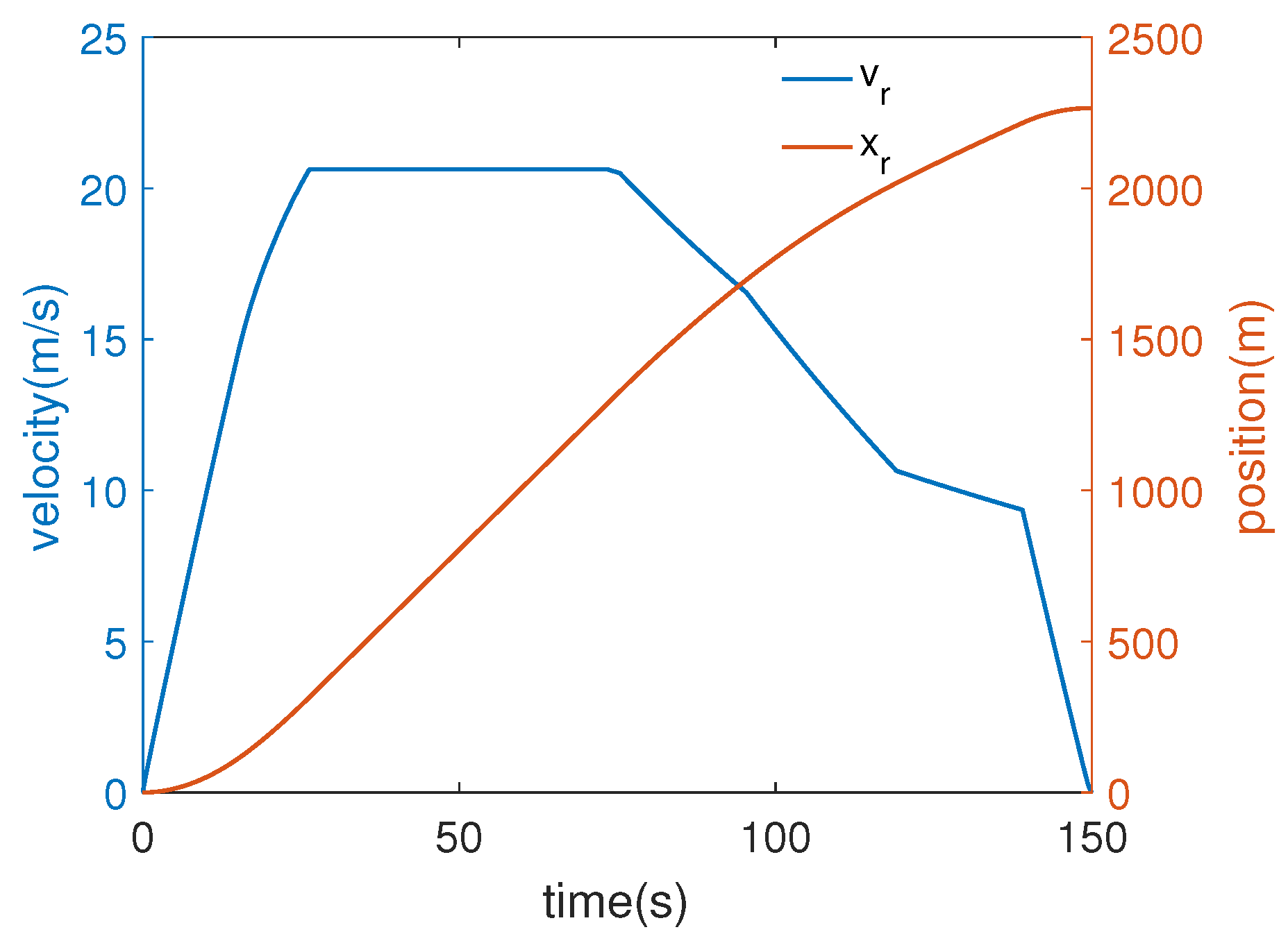
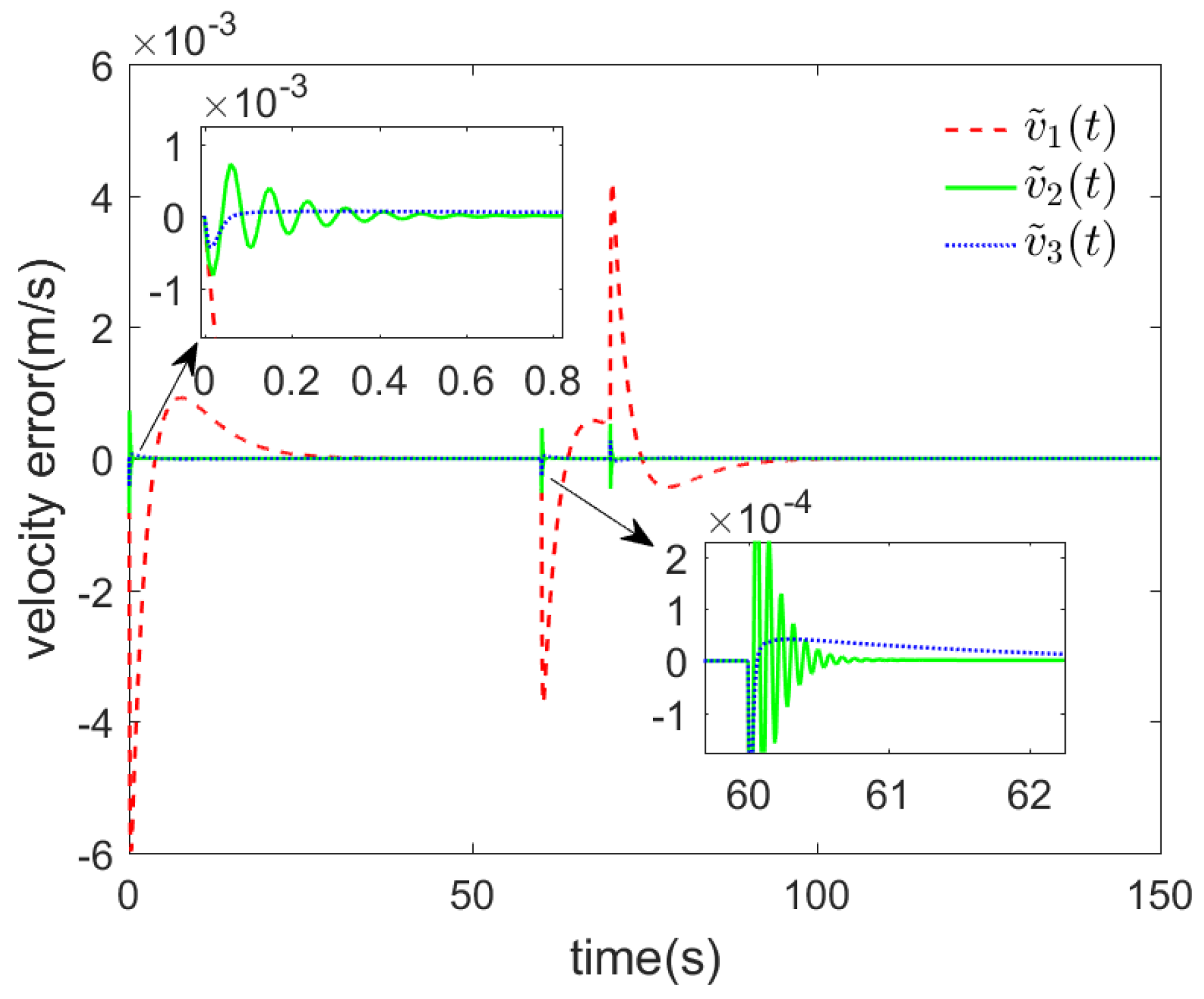
It exhibits higher tracking accuracy in terms of displacement and velocity, and the tracking error is in the range of [ 7.8091 × 10 4 , 2.7326 × 10 4 ] m and [ 0.0035 , 0.0018 ] m/s, which meets the punctual operation requirement of the UTRs.
(2)
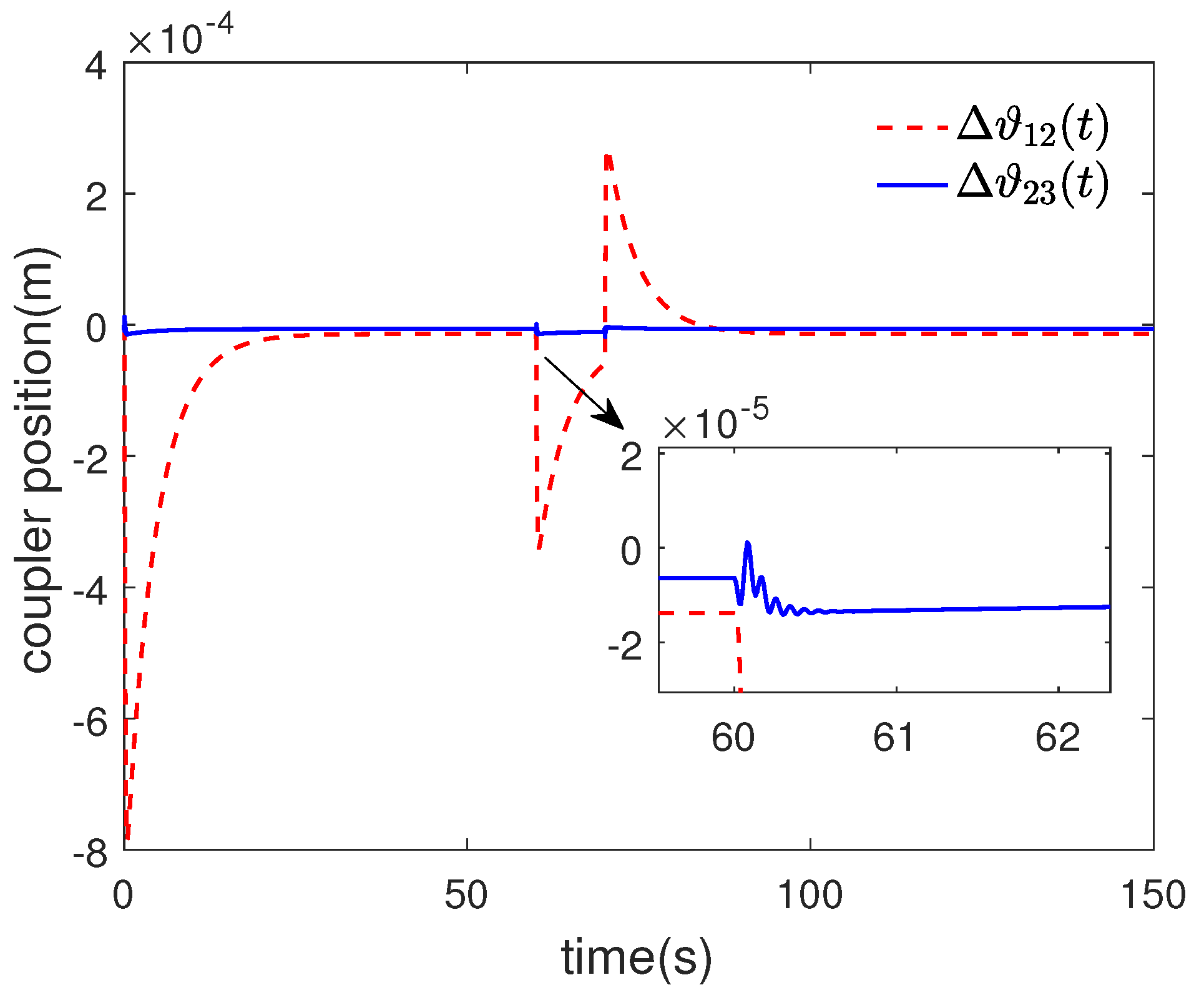
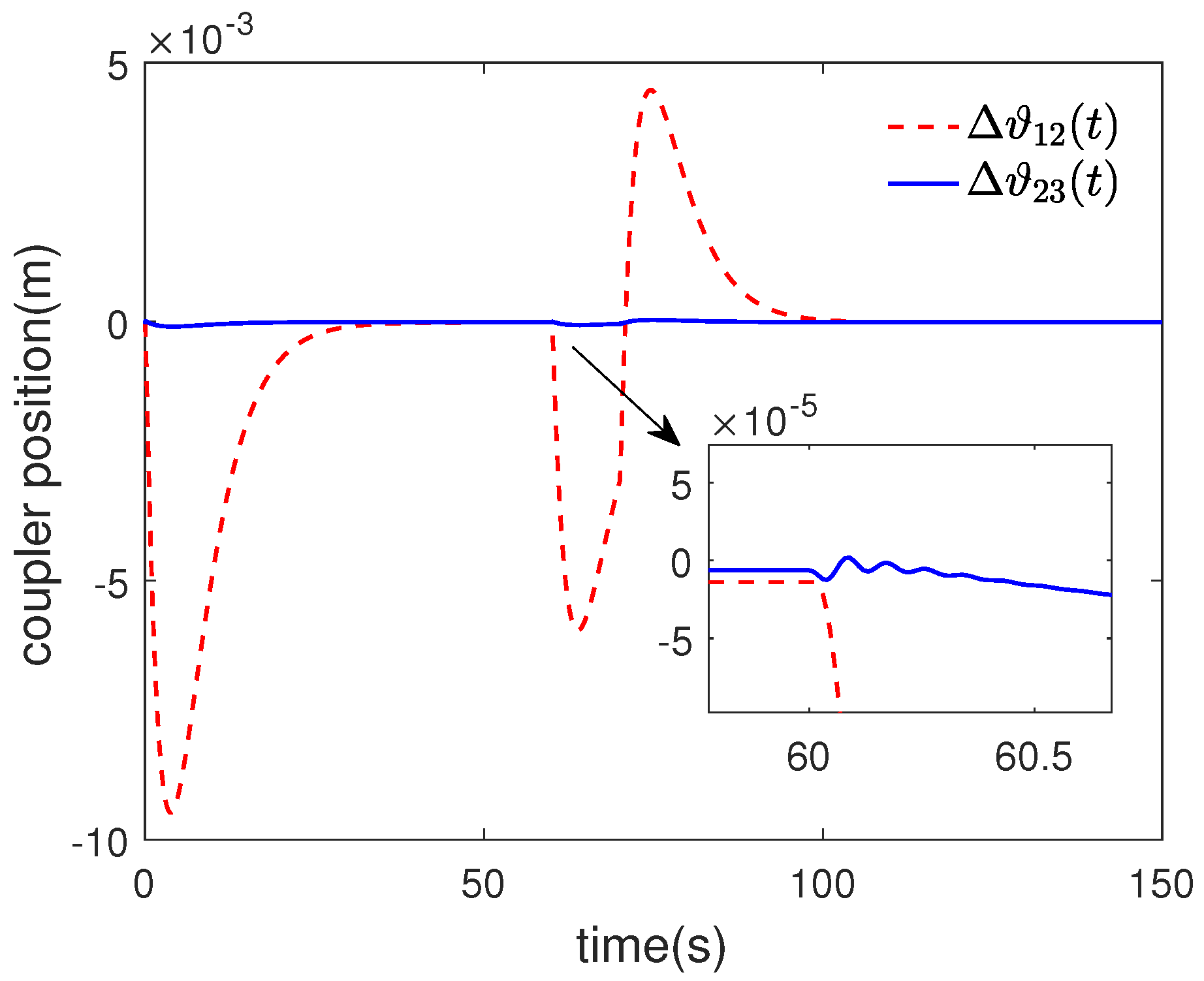
With a smaller coupler displacement, which meets safety specifications and ensures safer train operation.
(3)
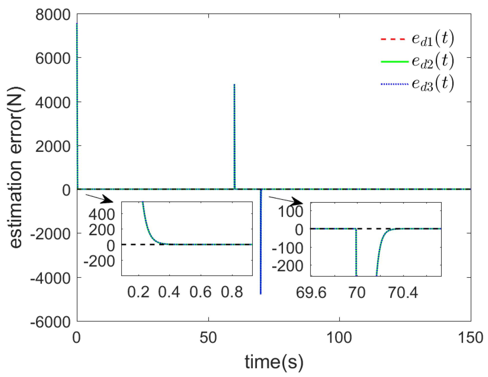
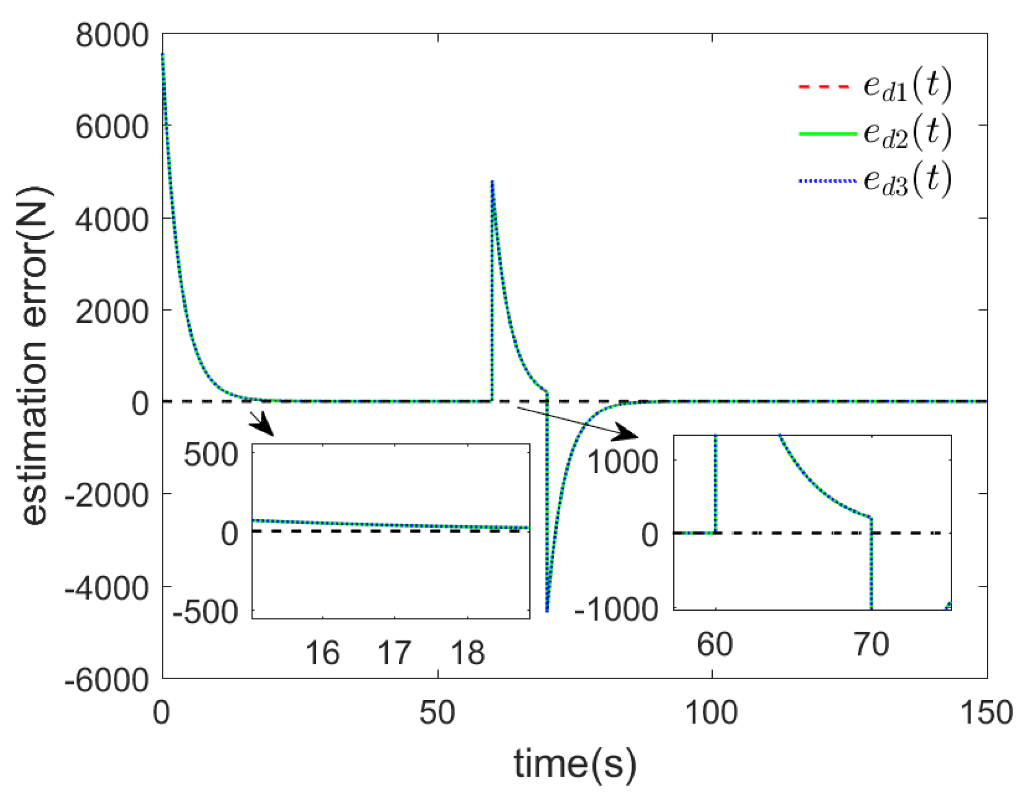
With stronger anti-disturbance capability, the error converges to zero faster after suffering external disturbance, which can make the URTs have better tracking performance.
In addition, the coupler position is closely related to the safe operation of URTs. Although the control method proposed in this paper ensures that the coupler position remains within a safe range, there is still a risk of exceeding the safety limit. Therefore, on the basis of this paper, considering the coupler displacement constraint will be the subsequent research direction.

Author Contributions

Conceptualization, Y.Z. and J.Z.; methodology, Y.Z. and J.Z.; software, J.Z.; validation, H.Y.; formal analysis, Y.Z.; resources, H.Y.; writing—original draft preparation, Y.Z.; writing—review and editing, Y.Z. and J.Z.; supervision, H.Y.; funding acquisition, H.Y. All authors have read and agreed to the published version of the manuscript.

Funding

This research was funded by National Natural Science Foundation of China (U2034211), the Technological Innovation Guidance Program of Jiangxi Province (20203AEI009), the Graduate Innovative Special Fund Project of Jiangxi Province (YC2022-s484).

Institutional Review Board Statement

Not applicable.

Informed Consent Statement

Not applicable.

Data Availability Statement

Not applicable.

Conflicts of Interest

The authors declare no conflict of interest.

References

  1. Bao, X.D. Urban rail transit present situation and future development trends in China: Overall analysis based on national policies and strategic plans in 2016–2020. Urban Rail Transit 2018, 4, 1–12. [Google Scholar] [CrossRef] [Green Version]
  2. Chen, X.N.; Ma, W.G.; Xie, G.; Hei, X.H.; Wang, F.; Tan, S.Y. A survey of control algorithm for automatic train operation. In Proceedings of the 2019 14th IEEE Conference on Industrial Electronics and Applications (ICIEA), Xi’an, China, 19–21 June 2019; pp. 2405–2410. [Google Scholar]
  3. Dong, H.R.; Ning, B.; Cai, B.G.; Hou, Z.S. Automatic train control system development and simulation for high-speed railways. IEEE Circuits Syst. Mag. 2010, 10, 6–18. [Google Scholar] [CrossRef]
  4. Domínguez, M.; Fernández-Cardador, A.; Cucala, A.P.; Gonsalves, T.; Fernández, A. Multi objective particle swarm optimization algorithm for the design of efficient ATO speed profiles in metro lines. Eng. Appl. Artif. Intell. 2014, 29, 43–53. [Google Scholar] [CrossRef]
  5. Yin, J.T.; Chen, D.W.; Li, L.X. Intelligent train operation algorithms for subway by expert system and reinforcement learning. IEEE Trans. Intell. Transp. Syst. 2014, 15, 2561–2571. [Google Scholar] [CrossRef]
  6. Lin, W.S.; Sheu, J.W. Optimization of train regulation and energy usage of metro lines using an adaptive-optimal-control algorithm. IEEE Trans. Autom. Sci. Eng. 2011, 8, 855–864. [Google Scholar] [CrossRef]
  7. Liu, J.Q.; Guo, H.L.; Yu, Y.X. Research on the cooperative train control strategy to reduce energy consumption. IEEE Trans. Intell. Transp. Syst. 2016, 18, 1134–1142. [Google Scholar] [CrossRef]
  8. Keskin, K.; Karamancioglu, A. Energy-efficient train operation using nature-inspired algorithms. J. Adv. Transp. 2017, 2017, 6173795. [Google Scholar] [CrossRef] [Green Version]
  9. Pu, Q.; Zhu, X.M.; Zhang, R.T.; Liu, J.; Cai, D.B.; Fu, G.H. Speed profile tracking by an adaptive controller for subway train based on neural network and PID algorithm. IEEE Trans. Veh. Technol. 2020, 69, 10656–10667. [Google Scholar] [CrossRef]
  10. Yang, H.; Fu, Y.T.; Wang, D.H. Multi-ANFIS model based synchronous tracking control of high-speed electric multiple unit. IEEE Trans. Fuzzy Syst. 2017, 26, 1472–1484. [Google Scholar] [CrossRef]
  11. Liu, H.E.; Yang, H.; Wang, D.H. Robust speed prediction of high-speed trains based on improved echo state networks. Neural Comput. Appl. 2021, 33, 2351–2367. [Google Scholar] [CrossRef]
  12. Li, S.K.; Yang, L.X.; Li, K.P. Robust output feedback cruise control for high-speed train movement with uncertain parameters. Chin. Phys. B 2014, 24, 010503. [Google Scholar] [CrossRef]
  13. Yao, X.M.; Park, J.H.; Dong, H.R.; Guo, L.; Lin, X. Robust adaptive nonsingular terminal sliding mode control for automatic train operation. IEEE Trans. Syst. Man Cybern. Syst. 2018, 49, 2406–2415. [Google Scholar] [CrossRef]
  14. Rui, S.; Shi, G. Robust control for T-S fuzzy multi-particle model of high-speed train with disturbances and time-varying delays. Int. J. Control Autom. Syst. 2022, 20, 3063–3074. [Google Scholar]
  15. Sariyildiz, E.; Oboe, R.; Ohnishi, K. Disturbance observer-based robust control and its applications: 35th anniversary overview. IEEE Trans. Ind. Electron. 2019, 67, 2042–2053. [Google Scholar] [CrossRef] [Green Version]
  16. Vo, A.T.; Truong, T.N.; Kang, H.J. A novel tracking control algorithm with finite-time disturbance observer for a class of second-order nonlinear systems and its applications. IEEE Access 2021, 9, 31373–31389. [Google Scholar] [CrossRef]
  17. Benevides, J.R.; Paiva, M.A.; Simplício, P.V.; Inoue, R.S.; Terra, M.H. Disturbance observer-based robust control of a quadrotor subject to parametric uncertainties and wind disturbance. IEEE Access 2022, 10, 7554–7565. [Google Scholar] [CrossRef]
  18. Xu, B.; Zhang, L.; Ji, W. Improved non-singular fast terminal sliding mode control with disturbance observer for PMSM drives. IEEE Trans. Transp. Electrif. 2021, 7, 2753–2762. [Google Scholar] [CrossRef]
  19. Wang, X.; Zhu, L.; Wang, H.W.; Tang, T.; Li, K.C. Robust distributed cruise control of multiple high-speed trains based on disturbance observer. IEEE Trans. Intell. Transp. Syst. 2019, 22, 267–279. [Google Scholar] [CrossRef]
  20. Leng, P.; Yu, P.; Gao, M.; Li, J.; Li, Y. Optimal Control Scheme of Maglev Train Based on The Disturbance Observer. In Proceedings of the 2019 Chinese Control Conference (CCC), Guangzhou, China, 27–30 July 2019; IEEE: Piscataway, NJ, USA, 2019; pp. 1935–1940. [Google Scholar]
  21. Chen, B.; Zhang, R.; Zhou, F.; Du, W. An Observer-Driven Distributed Consensus Braking Control Method for Urban Railway Trains with Unknown Disturbances. Actuators 2023, 12, 111. [Google Scholar] [CrossRef]
  22. Chen, D. Derailment risk due to coupler jack-knifing under longitudinal buff force. Proc. Inst. Mech. Eng. Part F J. Rail Rapid Transit. 2010, 224, 483–490. [Google Scholar] [CrossRef]
  23. Xu, C.F.; Chen, X.Y.; Wang, L. Model-independent adaptive fault-tolerant tracking control for high-speed trains with actuator saturation. Appl. Sci. 2019, 9, 4146. [Google Scholar] [CrossRef] [Green Version]
  24. Zhou, L.; Li, Z.Q.; Yang, H.; Fu, Y.T.; Yan, Y. Data-driven model-free adaptive sliding mode control based on FFDL for electric multiple units. Appl. Sci. 2022, 12, 10983. [Google Scholar] [CrossRef]
  25. Yang, C.D.; Sun, Y.P. Mixed H2/H cruise controller design for high speed train. Int. J. Control 2001, 74, 905–920. [Google Scholar] [CrossRef]
  26. Zhong-Qi, L.; Hui, Y.; Zhang, K.P.; Ya-Ting, F. Distributed model predictive control based on multi-agent model for electric multiple units. Acta Autom. Sin. 2014, 40, 2625–2631. [Google Scholar]
  27. Yang, J.; Chen, W.H.; Li, S.H. Non-linear disturbance observer-based robust control for systems with mismatched disturbances/uncertainties. IET Control Theory Appl. 2011, 5, 2053–2062. [Google Scholar] [CrossRef] [Green Version]
  28. Khalil, H.K. Nonlinear Control; Pearson: New York, NY, USA, 2015. [Google Scholar]
  29. Cao, Y.; Wang, Z.C.; Liu, F.; Li, P.; Xie, G. Bio-inspired speed curve optimization and sliding mode tracking control for subway trains. IEEE Trans. Veh. Technol. 2019, 68, 6331–6342. [Google Scholar] [CrossRef]
  30. Liu, G.F.; Hou, Z.S. Adaptive iterative learning control for subway trains using multiple-point-mass dynamic model under speed constraint. IEEE Trans. Intell. Transp. Syst. 2020, 22, 1388–1400. [Google Scholar] [CrossRef]
Figure 1. The in-train force analysis structure diagram of the URTs.
Applsci 13 07403 g001
Figure 2. Distribution of the URTs power unit.
Applsci 13 07403 g002
Figure 3. Block diagram of the URTs under IDOBC.
Applsci 13 07403 g003
Figure 4. The type B URTs formation structure diagram.
Applsci 13 07403 g004
Figure 5. Desired position curve and desired velocity curve.
Applsci 13 07403 g005
Figure 6. Position tracking error curves under IDOBC.
Applsci 13 07403 g006
Figure 7. Speed tracking error curves under IDOBC.
Applsci 13 07403 g007
Figure 8. Coupler position variation curves under IDOBC.
Applsci 13 07403 g008
Figure 9. Disturbance estimation error under IDOBC.
Applsci 13 07403 g009
Figure 10. Position tracking error curves under TDOBC.
Applsci 13 07403 g010
Figure 11. Speed tracking error curves under TDOBC.
Applsci 13 07403 g011
Figure 12. Coupler position variation curves under TDOBC.
Applsci 13 07403 g012
Figure 13. Disturbance estimation error under TDOBC.
Applsci 13 07403 g013
Table 1. Nomenclature.
SymbolDescription
x i ( t ) , v i ( t ) , and v ˙ i ( t ) Position, speed, and acceleration of carriage
u i ( t ) The control input of carriage
f i n i ( i + 1 ) ( t ) Coupling forces between ith and ( i + 1 ) th carriage
Δ ϑ i ( i + 1 ) ( t ) Coupler deformation length
κ The elastic coupling coefficient
SThe sum of the original length of the carriage and coupler
m i The mass of ith carriage
a i , b i , and c i The Davis coefficients
l r , α The length and center angle of the curve
θ The slope angle
l s The tunnel Length
f i ( t ) The running resistance of ith carriage
f a i ( t ) The additional resistance of ith carriage
O i ( · ) The unknown external disturbance of ith carriage
d L i ( t ) The lumped disturbance of ith carriage
x r ( t ) , v r The target position and speed
x ˜ i ( t ) , v ˜ i ( t ) , and u ˜ i ( t ) The position, speed, and control input error of ith carriage
LThe observer gain matrix
KThe controller gain matrix
d ^ L ( t ) The estimate of lumped disturbance
e d ( t ) The disturbance estimation error
ρ The actuator health factor
σ max ( Ψ ) , σ min ( Ψ ) The maximum and minimum singular values of the Ψ
Ψ The Euclidean norm of the matrix Ψ
S y m ( Ψ ) The matrix and its transpose sum Ψ + Ψ T
I n n × n dimensional unit matrix
The symmetric part of the matrix
where x i ( t ) , and v i ( t ) denote the position and speed of the ith carriage. f i n i ( i + 1 ) ( t ) and f i n ( i 1 ) i ( t ) represent that the carriage is subject to the coupling force of the i + 1 th carriage and i 1 th carriage. Δ ϑ i ( i + 1 ) ( t ) indicates the length of the coupler being stretched or compressed. ϑ i + ϑ i + 1 denotes the original length of the coupler when no deformation has occurred. 2 l is the length of one carriage.
Table 2. The URTs parameters.
Parameter Symbols (i = 1, 2, 3)Parameter Value
m 1 9.58 × 10 4 kg
m 2 9.56 × 10 4 kg
m 3 9.58 × 10 4 kg
a i 2.031 N/kg
b i 0.0622 Ns/mkg
c i 0.00187 N s 2 / m 2 kg
κ 8 × 10 4 N/m
2 l 23 m
ϑ i + ϑ i + 1 0.6 m
Table 3. Position error statistical analysis.
StrategyMPE (m)MNE (m)MAE (m)
IDOBC 2.7326 × 10 4 7.8091 × 10 4 2.1734 × 10 5
TDOBC 4.5 × 10 3 9.5 × 10 3 4.3076 × 10 4
Table 4. Speed error statistical analysis.
Strategy (m/s)MPE (m/s)MNE (m/s)MAE (m/s)
IDOBC0.0018−0.0035 6.8497 × 10 6
TDOBC0.0042−0.006 8.9933 × 10 5
Disclaimer/Publisher’s Note: The statements, opinions and data contained in all publications are solely those of the individual author(s) and contributor(s) and not of MDPI and/or the editor(s). MDPI and/or the editor(s) disclaim responsibility for any injury to people or property resulting from any ideas, methods, instructions or products referred to in the content.

