Abstract
Cereal straw is a biomaterial with great potential: about 144 million tons of biomass are grown annually in Europe. For any use of straw (fertilizer, biofuel, etc.), efficient chopping technology, i.e., the reliable and efficient operation of mobile or stationary choppers, is the key factor for further success. Since most of the straw is chopped at harvest time, the subject of the study is the wear of the combine’s chopping knives. Six blades of different materials and designs were tested under realistic conditions during wheat and rapeseed harvesting on 180 ha. The influence of hardness, composition, cutting edge angle, and position in the chopper on knife wear was analyzed. The study showed that the blades with the highest cutting edge hardness (568 ± 11 HV) and the lowest cutting edge angle (20.9°) had the lowest wear. The highest hardness of the induction hardened knives was due to the 0.42% carbon content of the steel. The study confirmed that wear was inversely proportional to the hardness of the cutting edge (the harder the cutting edge, the lower the wear) and directly proportional to the angle of the cutting edge (the higher the angle, the greater the wear). The SEM study showed that part of the tooth surface of the blades was covered by permanent deposits of the material to be shredded. This wear was not caused by the interaction between straw and blade but by microabrasive particles that contaminated the straw.
1. Introduction
In 2020, the area of land used to grow cereals in EU countries was 159 million ha. Wheat, spelt, barley, and triticale are grown in the EU, which are best adapted to the climatic conditions in Europe and provide a high straw mass. It is estimated that 144 million tons of wheat straw alone are produced annually in Europe [1].
The main chemical (elemental) components of straw are carbon (41.3–46.0%), hydrogen (5.33–6.07%), nitrogen (0.93–1.38%), oxygen (33.7–39.0%), and sulfur (0.10–0.15%) [2]. In addition, a significant portion of straw (about 80%) consists of nonnitrogenous organic compounds (lignin, 14–17%; cellulose, 32–34%; and hemicelluloses, 33–45%); hot water soluble compounds, 7–19%; and ash, 5–12% [3]. Straw ash also consists of the internal and external microabrasive contamination of straw.
Straw is the largest “waste” in grain harvesting. Straw is chopped or placed in windrows, dried, and pressed at 15% moisture content. The pressed straw is used in livestock production for feed, bedding, and vegetable production. Straw biomass is being explored as a renewable resource with high potential and low emissions as a primary fuel in cogeneration plants (electricity and heat production) [4]. When straw is used for biofuel production, it is first chopped and then pelletized [5].
Straw is an important feedstock for biogas (methane) production. The lignocellulose must be chopped to achieve rapid biomass degradation (biodegradation). Studies show that chopping increases the surface area and thus increases the speed and yield of methane production. The proper preparation of biomass increases the methane yield from 16% to 99.5% [6].
After harvesting, the straw is collected from the ground, which significantly damages the soil. Chopping and spreading straw is an effective method to reduce crop waste and improve soil quality. Straw plays an important role in the agroecosystem and directly and indirectly affects the physical, chemical, and biological processes in the soil [4]. Studies show that straw is rich in nitrogen, phosphorus, potassium, and other nutrients for plant growth. The addition of chopped straw to the soil increases the oxygen and humus content and the friability of the soil, which leads to a higher content of microorganisms [7].
Comminution of plant waste is complicated due to the heterogeneous and nonisotropic nature of these materials [8]. The choice of blades for the straw chopper of the combine harvester is crucial for the chopping quality. The benefit of straw to the soil depends on the fractions into which the straw is chopped and distributed. The length of the chopped straw is directly affected by the speed of the chopper shaft—as the speed increases, the size of the chopped straw decreases [8]. The speed of the shaft determines the speed at which the air velocity moves with the chopped straw in the chopper. The goal is to distribute the chopped straw mass evenly over the soil surface, but this is often difficult to achieve due to variations in wind speed and direction and terrain [9]. The shorter the straw, the more easily it is incorporated into the soil and the faster it decomposes. The optimum length of chopped straw for best incorporation/mixing with the soil is up to 30 mm [10]. The open blades of the chopper damage the straw less, and the decomposition (conversion to fertilizer) is longer and less efficient. After spreading the straw on the stubble, the straw is treated with fungicides to make it decompose faster and more evenly [11].
The classical structure of a straw chopper (straight blades) is shown in Figure 1. The blades are hinged in pairs to the axles mounted in the fastening loops. The fastening loops are generally arranged in four rows along the shaft and welded symmetrically to the chopper shaft axis. The loops can be arranged in a straight or spiral pattern. As the shaft rotates, the blades, under centrifugal force, are positioned parallel to the radius of the chopping drum under centrifugal force (Figure 1a). The blades cut the straw as it passes between the counter blade plates. The faster the chopper shaft rotates, the finer the cut.
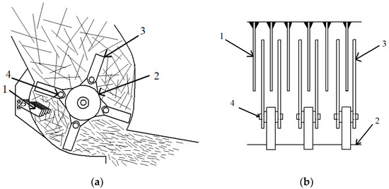
Figure 1.
The principal design of a cereal straw chopper: (a) 1—adjustable counter blade; 2—chopper shaft; 3—blades; 4—blade attachment axes. (b) Straight blade connection to the chopper shaft.
The blades are subjected to high centrifugal forces as the Claas combine harvester chopper rotates at speeds of up to 3550 min−1. Therefore, the blade strength reserve factor is an important factor influencing the durability of the blades and the damage that can occur. The higher the coefficient of safety, the longer the blades will last, and foreign objects will cause less damage. The tests were carried out using a numerical simulation (at 2400 min−1), which reproduced the performance parameters of a real blade when chopping wheat straw. It was found that this type of blade must have a strength of at least 430 MPa, and the stresses generated in the structure during operation were 267.1 MPa. Therefore, the coefficient of safety in the simulation was 1.61, …, 1.72, while the minimum recommended coefficient was about 1.5 [12].
Various literature sources indicate that using hardened spring steel 65 Mn to produce blades can significantly reduce their wear [12].
Comparing the arrangement of the chopper blades along the shaft axis with the spiral arrangement also shows advantages. The longitudinal arrangement ensures that the straw mass is chopped evenly, despite the possibility of uneven dropping of the straw on the chopper (e.g., when the combine harvester is tilted), which would be difficult to achieve with a chopper with a spiral blade layout. This increases the likelihood of clogging the straw chopper and deterioration of the chopping quality. In addition, the longitudinal layout reduces the load on the chopper shaft, with a calculated load reduction of ~9% compared with the spiral layout [12].
Studies on using straw as an important renewable raw material show that the essential element in the initial stage of processing for use is the chopper blade, which is made of a constructional steel strip, usually with a hole for mounting and two blades. Manufacturers offer different types of straw chopping blades, but the most common are straight, doublebladed blades with serrated or smooth blades. Straightbladed, doubleedged blades are not as good as the clippedblade type in terms of chopping quality, but they are cheaper due to the simpler manufacturing process. In addition, curved blades reduce the energy required for the chopping process compared with straight blades. This is due to the different angles of incidence between the curved blade and the straw. The lowest energy demand for cutting is required when the blade of the blade meets the straw at an angle of 20–30° [8]. This results in a lower load on the combined harvester and lower fuel consumption [13].
Wear varies depending on the output—the more the combine works, the more the blades wear off. The price of a blade is determined not only by the type of blade (longer production process) but also by the type of steel used, the hardening of the blade (also reinforcement), and the anticorrosive coating. A combine harvester chopper has between 52 and 108 blades [14], so the effective working time of blades is also part of the production costs. There is not much research on the topic of chopper blade wear. In some cases, it is evident that the study was not carried out systematically. For example, the mechanical damage to the blades shown in the illustration (Figure 2) indicates that the blades used for the reassessment (at higher outputs) were not presented correctly. Because different blades were used to show the wear when comparing different work times and the analyzed blades had mechanical damages. Next are presented wear data about the various smooth and serrated chopper blades with different properties (Figure 3 and Figure 4), but no detailed study, analysis, or discussion is presented.
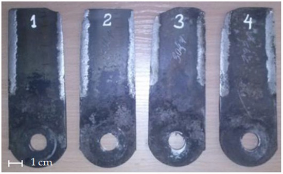
Figure 2.
The effect of the surface area of the blades of the grain harvester Rostselmash Acros straw chopper IRS1500 on visual defoliation: 1–47 ha, 2–110 ha, 3–162 ha, and 4–225 ha [15].
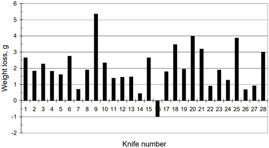
Figure 3.
Weight loss over entire harvest season for each of the smooth knives [14].
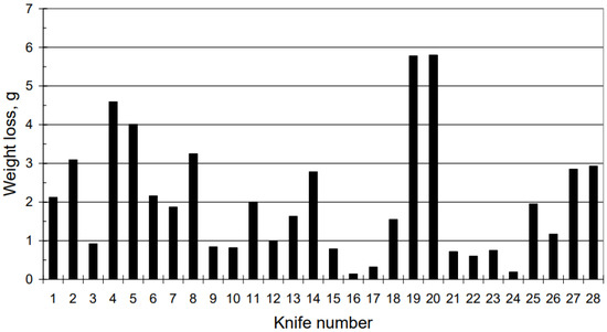
Figure 4.
Weight loss over entire harvest season for each of the serrated knives [14].
From the presented data, it is difficult to explain the three or even 10 times difference in the blade wear rates, unless the study was conducted using blades with very different characteristics (composition and hardness) or a combined harvester with extremely uneven straw mass supplied to the chopper.
In the literature, one often finds dependencies between the wear and blade hardness, which are related to the material composition. The presence of harder structures (e.g., WC impurities) results in higher blade wear resistance. Various techniques can be used to increase the hardness, such as laser coating [16]. However, again, it is difficult to explain the different wear of blades when the conditions are similar [14,15]. It seems that not only material properties play a role in the mechanics of blade wear.
The literature review shows that regardless of where grain straw is used (fertilizer, renewable biofuel, etc.), the most important guarantee of successful use is compliance with shredding technology requirements, i.e., reliable and efficient operation of the shredding blades.
Other factors also affect the wear of the blades: the varieties of harvested plants (physical and mechanical properties), humidity, contamination of the chopped mass with abrasive particles (internal and external), and the composition of the plant biomass, which affects the aggressiveness of corrosion, etc.
The purpose of this study is to investigate the structural factors (blade hardness, shape, and position on the shaft) that influence blade wear. Studies show a wide variation in wear data under relatively uniform conditions. Therefore, it is important to find other significant factors that influence wear in mice.
2. Methodology
The Claas Tucano 450, 220 kW (CLAAS KGaA mbH, Harsewinkel, Germany) combine harvester was chosen for the tests, equipped with a 9 m3 hopper and a CLAAS Vario V660 mower. A belt drive rotated the chopper shaft at 3550 min−1 rotation frequency. The crushing shaft of a CLAAS Tucano 450 combine harvester is shown in Figure 5.
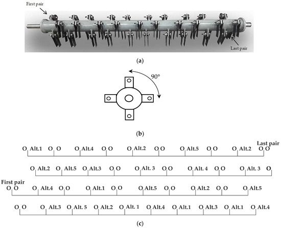
Figure 5.
Chopper shaft of a Claas Tucano 450 combine harvester (a), angle position of loops (b), and position of the blade on the loops (c).
Eighty blades were hinged on the chopper shaft in four rows (every 90°; Figure 5b) on 40 loops. Two blades were fixed on one loop axis with a 25 mm gap between the blade planes. The chopper blades were hardened by induction heating. The blades were doubleedged, with serrated blades with overall dimensions of 173 × 50 × 4 mm (Figure 6a).
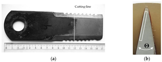
Figure 6.
Schemes for measuring the hardness of the used blade: (a) view of blade and cross−section cutting line and (b) microhardness test area in the cross−section of the blade (white rectangle 3.0 × 0.3 mm, 10×).
The 55 blades were used to determine the factors influencing the wear (“original” and five of other manufacturers’ alternatives, denoted by Alt. 1, …, Alt. 5) and randomly arranged and installed on the shaft of the chopper. The blades from the alternative manufacturers were positioned on the shaft to determine the average wear: one blade at the beginning and the end of the shaft, one blade in the center of the shaft, and the remaining two blades at one−fourth of the length of the shaft from the shaft end (Figure 5c). The remaining positions were filled with “original” blades.
The harvest occurred on a farm in Šakiai district, Lithuania, in August 2022. An quantity of 130 ha of wheat (varieties Etana, Skagen) and 50 ha of oilseed rape (Dominator) were harvested. The average working speed of the combine harvester was low (4 km/h) due to crop lodging.
The blade wear was measured to the nearest 0.001 g with a balance KERN 420–3NM (KERN & Sohn GmbH, Balingen, Germany); the blade chemical composition was analyzed with an Oxford PMI−MASTER PRO spectrum analyzer (Berg Engineering & Sales Company, Inc., Rolling Meadows, IL, USA); and the microhardness was measured with a microhardness tester PMT 3 (JSC LOMO, Saint Petersburg, Russia) on the scale HV with a load of 50 g and a 10 s penetration of the indenter into the sample. The microhardness was tested at a distance of at least 0.03 mm from the edge (sector in Figure 6b). The measurement of the macrohardness was performed using the Rockwell digital hardness tester iRock DR2/DS2/TR2. Due to the bevel of the cutting edge, the measurements (with the HRC parameter) were taken only on the tip of the blade, which was visually thermally affected by the induction heating.
For the microstructure study, samples (of unused blades) were cut using a Struers Secotom 5 (Struers ApS, Ballerup, Denmark), ground, and polished with a diamond polishing paste (9 and 3 µm grade) using a Struers Tegramin 20 (Struers ApS, Denmark). The polished surfaces were etched with HNO3 4% acid ethyl alcohol solution, and the microstructure was examined with a metallographic optical microscope, Nikon Eclipse MA 100 (Nikon, Tokyo, Japan).
As a prognostic parameter of the wear intensity [17], the roughness measurements of the worn blades’ edge surfaces were performed with a Mahr Surf G25 profilometer (Mahr GmbH, Göttingen, Germany). The measuring distance was 5.6 mm.
The surface morphology and composition were analyzed using scanning electron microscopy (SEM; Hitachi S−3400N−II, Tokyo, Japan) and energy dispersive X−ray spectroscopy (EDS; XFlash 5040 QUAD) detectors from Bruker (Lithuanian energy institute, Center for Hydrogen Energy Technologies, Kaunas, Lithuania).
The cutting−edge angle was calculated from the length and width of the cutting edges. A Mitutoyo 500−754−20 ABSOLUTE Digimatic Caliper IP67 0–300 mm (unit value 0.01 mm, Mitutoyo Europe GmbH, Neuss, Germany) was used.
The influence of the cutting−edge (HV) hardness and of the cutting−edge angle (Θ) on the wear was analyzed by Matlab 2022a software by uploading an Excel data file. The Curve Fitter tool was used, and a 95% confidence level was set. Several models were tested, and only the one with the highest R2 value and the lowest residual errors was selected for further analysis. The reliability of the results was assessed by performing a correlation analysis between the simulation and the experimental results in Excel based on the equation obtained.
3. Results
The blades used to chop the straw from the 180 ha harvested area are shown in Figure 7. An arrow indicates the worn edge of the blades. The second edge was not worn (the blades were not turned over). During use, most of the protective coating on the blades (anti−corrosion coating) had been worn away. Some of the working surfaces of the blades were partially covered with deposits of organic material (resins), lignin, cellulose, hemicelluloses, or other straw components. Cleaning the blades with the organic solvent 2−propanol 70% (a pure solution from Carl Roth GmbH + Co KG, Karlsruhe, Germany) does not remove the thin coatings.
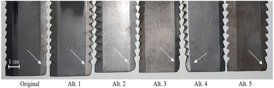
Figure 7.
The visual typical difference between non−worn and worn chopping blades edges tested from “Original” to Alt. 5 after chopping the straw of cereal and oilseed rape from 180 ha area.
The durability of the blades was also greatly affected by damage caused during use, which reduced the life of the blade and the quality of the chopping. The blades had been damaged by foreign objects (metal rods, stones, etc.) entering the thresher. Their wear was not typical and was not included in the calculation of the wear averages. The damage affected only the teeth (hardened zone) and was not the cause of the blade body breakage.
The cutting−edge angle, average wear during testing, hardness, and chemical composition of the chopper blades are given in Table 1.

Table 1.
Cutting edge angle, average wear during testing, hardness, and chemical composition of the chopper blades.
The wear rates for all 80 chopper blades are shown graphically in Figure 8. Red color indicates wear significantly higher than average, and green—significantly lower.
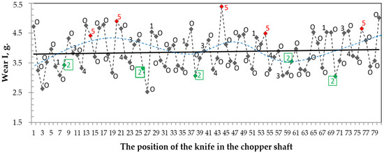
Figure 8.
Wear of all 80 chopper blades used in the study depending on the position on the shaft: O—original; 1–5—alternatives. Red color indicates wear significantly higher than average, and green significantly lower.
The minimal wear of the Alt. 2 chopping blades was due to the highest edge hardness (568 ± 11 HV) obtained by induction hardening due to the highest carbon amount of the blade steel (0.42% C). The highest wear of Alt. 5 was due to the lowest carbon amount of the steel used (0.16% C), the low chromium content (only 0.49% Cr, compared to about 1.0% for the other blades), and the three to four times lower vanadium content (Table 1).
The effects of the hardness HV on the wear I of the blades and of the carbon (C) amount on the chopper blades cutting edge hardness HV are shown in Figure 9.
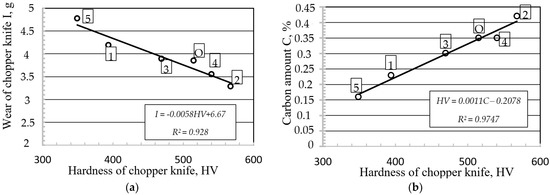
Figure 9.
The effect of the carbon amount in the steel of the chopper blade on the hardness HV of the cutting edge (a) and the effect of the hardness HV on the blade wear I (b): O—original; 1, …, 5—alternatives.
The carbon amount (0.16 to 0.42%) in the steel directly influenced the possibility of hardening the cutting edge, suggesting a potential increase in blade life and a reduction in operating costs [17].
The study showed that the current design of the shredder (alignment of the blades along the axis) did not ensure uniform wear intensity and thus simultaneous achievement of the critical conditions. The edge blades of the chopper shaft exhibited the highest wear (4.8–5.0 g, presumably due to the higher straw mass density at the edges of the chopper). The next two blades exhibited lower wear (about 3.0–3.6 g), the next two higher (about 4.0–4.8 g), the next two lower, etc. (Figure 8 and Figure 10). This was a statistically significant difference in attrition. This sinusoidal regularity was likely influenced by the uneven distribution of straw along the length of the chopper shaft as the straw moved through the straw walkers. The systematic differences in wear were caused by the non−uniform arrangement of the blades along the chopper shaft. This regularity was evident in a randomly selected test of six blades from different manufacturers (designs), although statistical analysis showed that the average wear of the blades of the different manufacturers was different (Figure 11).
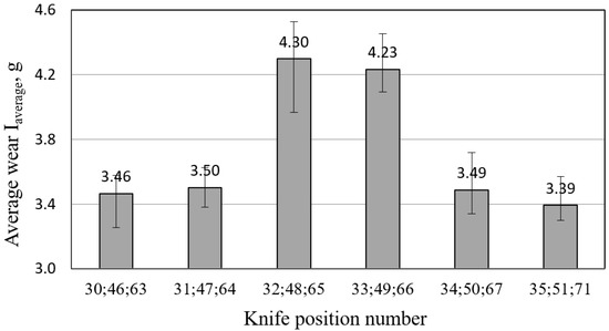
Figure 10.
Influence of the mounting positions of the “original” blades on the shaft of the chopper on the average wear.
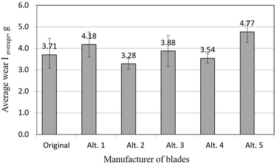
Figure 11.
Average wear of blades from different manufacturers and their dispersion intervals.
The average wear rates of the different manufacturers’ shaft grinding blades are shown in Figure 11. The differences were not statistically significant for all average wear rates. However, when evaluating the wear of the blades by weight, a statistically significant difference (95% probability) was found among different manufacturers (Alt. 1 and Alt. 2, “original” and Alt. 5, Alt. 2 and Alt. 5, and Alt. 4 and Alt. 5).
Statistically, these differences in wear were significant in terms of average wear and wear dispersion intervals (Figure 11). It could be assumed that the uneven wear caused by the chopper design would eventually lead to an imbalance in the chopper shaft. As the chopper output increased, about 50% of the chopper blades were worn more intensively and reached a critical condition. Meanwhile, the other 50% of the blades could still be used.
The blade’s cutting edge received the main load, causing the highest stresses and wear. Therefore, the teeth’s wear (edge rounding) started at the tip and spread away from the cutting edge (or tip, in serrated blades) as the teeth descended. The greater the wear (tip rounding), the greater the angle of contact (close to 90°) between the plant mass to be chopped and the blade, the greater the load on the cutting surface, and the higher the energy consumption.
Using the patterns of erosive wear, we assumed that the different blade angle influenced the wear. The falling angle of the straw mass with abrasive dust on the surface created a different intensity of wear [18]. The mechanism of erosive wear by micro−abrasive particles at an angle of 10–15° was micro−cutting [19].
The determined values of wear and blade angle were a bit complicated because of the different hardness of the blades. However, the hypothesis was that the smaller the angle of the sharpened blade, the lower the wear could be raised, based on points with close hardness values (Figure 12, connected with a dotted line). That led to the conclusion that the longer the blade was used, the more its blade would round, and the more it would wear while performing the same amount of work.
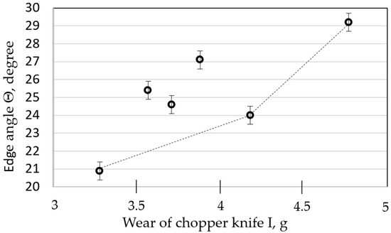
Figure 12.
The influence of the edge angle Θ on the wear of chopper blade I.
The wear intensity, depending on the main influencing factors (hardness of the cutting edge of the blade and the angle of the tip), varied according to a quadratic function, which is described by the following equation (95% confidence level) (Figure 13a):
where HV is the Vickers hardness of the cutting edge and Θ is the blade angle of the blades, in degrees.
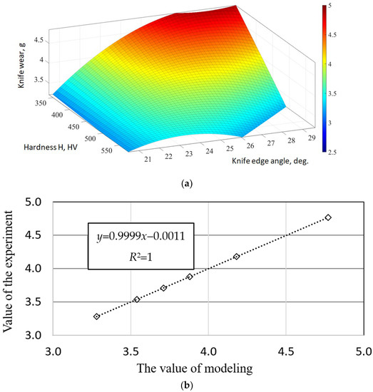
Figure 13.
Simulation results: (a) plot of the dependence of wear I on the main influencing factors (H, Θ). (b) Plot of the correlation between the experimental and the simulation data (sum of the squares of the residual errors, SSE = 1.664 × 10⁻²⁷).
The correlation plot between the experimental and simulation data (sum of squares of residual errors, is shown in Figure 13b.
The study found that the hardest blades had the least wear and, therefore, the highest potential resource.
The metallographic study showed that the hardest blade, Alt. 2 (HRC 53), was dominated by a troostite (white arrows, Figure 14b) with a martensite (dotted arrows, Figure 14b) microstructure. On the other hand, the lowcarbon, lowhardness blade, Alt. 5 (HRC 37), had a predominantly fine pearlite (white arrows, Figure 14a) microstructure with troostite (dotted arrows, Figure 14a). The specific features of the hardening process were the low metal mass of the blade, the rapid induction heating accompanied by rapid cooling by radiation, and insufficient time before the start of hardening for a complete structural transformation of the heated steel.
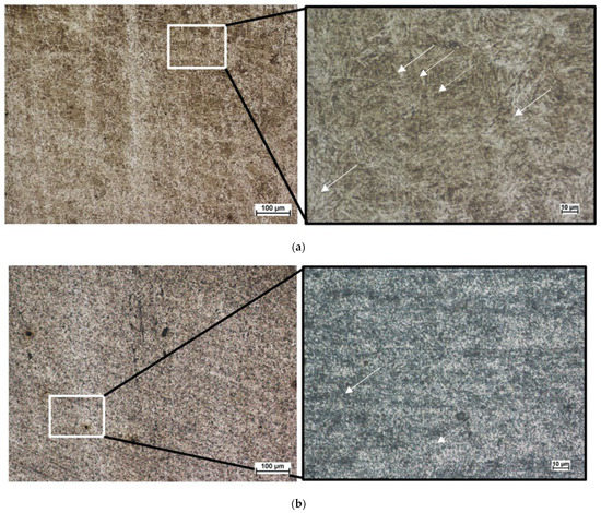
Figure 14.
Microstructures of the most and least worn blade steels (100× and 500×): (a) Alt. 5 and (b) Alt. 2.
When the tips of the blade teeth (blades), on which grain straw and other things fall at an angle of ~70–90°, began to wear out, the mass of crushed plants began to be covered by heterogeneous thin layers of plaques (resins) of plant origin. The thickness of these heterogeneous resins was up to 5–7 µm. The area of these plaques could reach up to onethird of the surface of the blade (Figure 15a). These resins were not removed by cleaning the surfaces with an organic solvent prior to examination at SEM. The deposits were formed due to the friction of the steel of the blades and the mass crushed by the impact, and the temperature was sufficiently strong mechanically (especially the adhesion parameters) since the blades were subjected to high centrifugal forces. At a rotational speed of the chopper shaft of 3550 min−1, a centripetal acceleration of 33,685 m/s2 acted on the blade tips. The plaque increased the friction between the mass to be shredded and the cutting surfaces of the blades, so that the shredder started to work less efficiently.
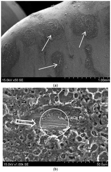
Figure 15.
SEM images of plaques of plant origin (sample Alt. 4) on the surface of the blade teeth (→, 50×): (a) resin layer and blade surface damaged by abrasive particles (○, ~25 µm, 1000×) and (b) ⇨—direction of movement of chopped straw.
The resinous layer was damaged (and removed) by the abrasive particles in the grinding mass (Figure 15b), thus breaking down and renewing. The resin layer damaged by an abrasive particle and a scratch of ~25 µm is shown in Figure 15b. This indicated that the abrasive particles damaged the resin layer on the surface of the blade, although it could withstand high mechanical loads caused by centrifugal forces.
We assumed that the wear of the straw chopper blades was caused by microabrasive particles, which is confirmed in Figure 16. The analysis of the blade surface of the blades (Alt. 1 and Alt. 3; Figure 16a and Figure 17b) showed the mechanical effects (indentations, scratches, and scuffs) of micrometric size (up to 10, …, 15 µm), which were probably caused by the contact with microabrasives (SiO2, Al2O3, etc.). When the contact angle between the crushed mass and the blade was less than 45 degrees, the surface of the teeth showed little deposition of plant residues (resin), while corrosionrelated damage occurred (Figure 16).
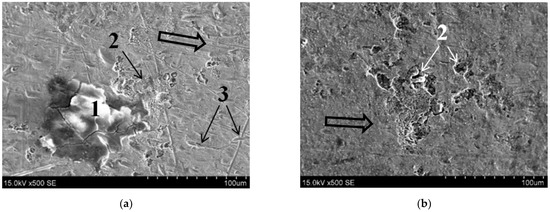
Figure 16.
The surfaces of the blades ((a) Alt. 1) and (b) Alt. 5) with (500×) a resinous plaque stain (1), areas affected by point corrosion (2), and signs of abrasive wear (3). ⇨—direction of movement of chopped straw.
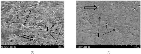
Figure 17.
SEM images of the blade surface (Alt. 3): (a) 45–60° falling angle, 1000×; (b) 20–35° falling angle, 500×. Here 1 indicates traces of microcutting, and 2 indicates plastically deformed surface microfragments. ⇨—direction of movement of a chopped straw.
The nature of the damage to the blade teeth depended on the angle of incidence of the abrasive particles on the surface (Figure 17).
After the blade was blunted (rounded), the differences in the angle of the abrasive falling on the surface became visible. At the tip of the blade, the microparticles fell at an almost perpendicular angle (the wear occurred according to the principle of deformation/redeformation of the microvolume; Figure 17a). At the same time, the rest of the surface was dominated by the microblade wear (Figure 17b). The analysis of the surfaces showed that in the case of microabrasive effect, microsurfaces were plastically deformed/cut by solid particles (1), and metal microparticles were separated from the surface (2) (microvolume) (Figure 17a). At a drop angle of about 20–35°, the effect of the abrasive on the surface is shown in Figure 17b.
The composition of the steel surface of used blades, determined by EDS, is shown in Table 2. This composition corresponded approximately to the composition of the blades determined by spectral analysis (Table 3): 91.7–92.6% iron, 3.29–3.86% oxygen, and other elements on the surface of used blades. The increased oxygen content on the surface of the blades was a natural consequence of the oxidation process at temperatures higher than ambient. Unlike EDS, the spectral analysis method used to detect the chemical composition of blade steel did not detect oxygen (Table 1). Other elements found on the surface of the blades (higher carbon content than steel, aluminum, calcium, potassium, and sodium) were due to the interaction with the chaff mass and contamination of the straw mass with abrasives. Silicon, manganese, chromium, and carbon are constituents of steel (Table 1).
Table 2.
The hardness of the blades, the initial angle, and the wear of the blade.
Table 3.
Chemical compositions of the resincontaminated surface of blade Alt. 2 and the clean surface of blade Alt. 5 (EDS analysis).
A solid coating of resinous plant debris formed on the surface of the blade (Figure 18a), which cracked as it dried, and the pores showed the release of gases during the formation of this coating. The main constituents of the resincontaminated surface of the Alt. 2 blades (EDS analysis) are listed in Table 3, and the spectrum of chemical composition is shown in Figure 18b. Silicon and aluminum are abrasive particles that remained in the resin. Iron, carbon, and steel alloy elements (silicon, manganese, and chromium) were components of the steel analyzed through the resin film. The high amounts of oxygen and carbon in the resin film were plant residues.
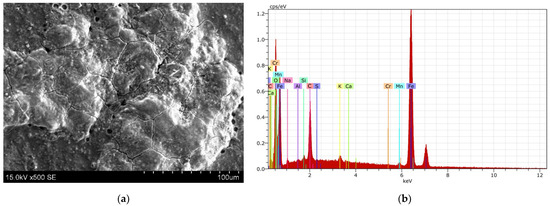
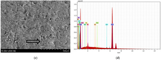
Figure 18.
SEM image of the teeth surface of resincontaminated blade Alt. 2, 500× (a) and spectrum of the chemical composition of resins (b). SEM image of clean (wearing) surface Alt. 5, 500× (c) and spectrum of the chemical composition of the surface (d). ⇨—direction of movement of chopped straw.
The SEM image of the “clean” surface (Alt. 5), on which no scales were formed due to the low angle of falling of the chopped mass, and the spectrum of the chemical composition of this surface are shown in Figure 18c,d.
The surfaces of the blades with the lowest hardness were subject to the greatest mechanical damage and wear (Figure 19).
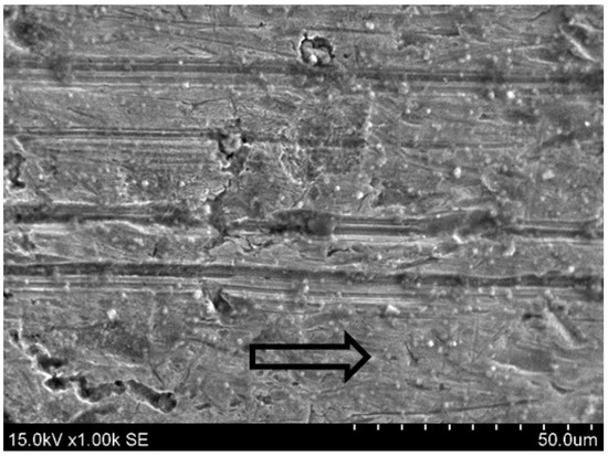
Figure 19.
The blades with the lowest hardness (Alt. 5) are the most vulnerable to mechanical damage (1000×). ⇨—the direction of movement of the chopped straw.
The initial surface roughness of the blades (main cutting planes) was quite different and ranged from 0.226 to 0.589 µm (Figure 20). It can be assumed that it was influenced by blade manufacturing technology—the method and modes of machining technology. Due to the chopping work, the roughness of the blade surfaces may increase or decrease during the wear process, and it may be related to the blade’s hardness. The results showed a general trend in which the lower the hardness of the blades, the greater the changes in roughness that occurred during use. From Figure 21, it can be seen that there was a direct relationship between blade’s hardness and roughness when wheat and canola were harvested on 180 ha. Of course, the inverse relationship between hardness and wear can also be seen.
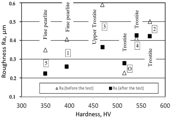
Figure 20.
Roughness Ra of the chopper blades (main cutting planes) of different hardness before and after the production test.
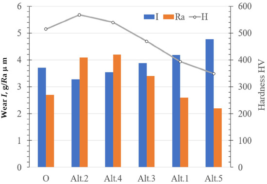
Figure 21.
Roughness Ra, wear I, and hardness of the chopper blades (main cutting planes) after the field test.
As the hardness increased, the roughness of the surface usually decreased when the abrasive was fixed.
If the roughness (especially the profile of worn surfaces) was related to the microstructure, the direct relationship between hardness and roughness could be explained.
The microstructure of the original, Alt. 2, and Alt. 4 blades was predominantly trostite with martensite inclusions (Figure 6b). The profiles show (Figure 22, Alt. 2 and Alt. 4) that the roughness value increased due to the reverse peaks. That peak was less than the dominant structure in worn martensite inclusions. The structure of sample Alt. 3 was fine pearlite with trostite.
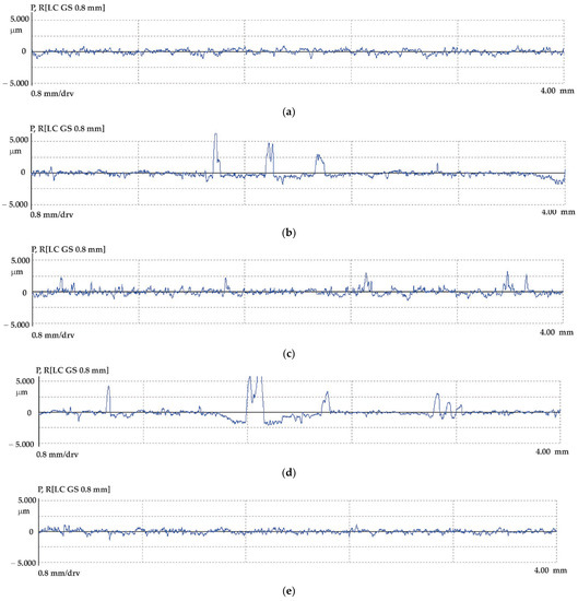
Figure 22.
Profiles of wearied blades surfaces: (a) Alt. 1, (b) Alt. 2, (c) Alt. 3, (d) Alt. 4, and (e) Alt. 5.
Correspondingly, the harder trostite structure showed less wear. Alt. 1 and Alt. 5 had mostly uniform fine pearlitic structures with lower hardness compared with others. The wear of it was higher, and the surface was smothered.
4. Discussion
The mechanical properties of steel blades (350, …, 568 HV) and straw are fundamentally different, so the wear caused by direct chopping of straw would be extremely slow [20]. The wear is not caused by the direct interaction between the straw (main components lignin, cellulose, and hemicelluloses) and the blade but by the dust and microabrasions covering the straw. The more grain, rapeseed, or other crops are spread on the field, the more the plants are pollinated and covered with fine soil particles, so the wear results of the interaction between the chopper blades and the straw mass can be explained from a tribological point of view. Chopper blades moving at ~91.6 m/s are affected by erosion (microabrasive particles) [18]. Based on the laws of abrasive wear processes (solid particle erosion wear) [19], it is reasonable to manufacture blades from spring or tool steels with higher carbon content (compared with the steels investigated in the study).
When using a shredder, the wear of the blade teeth creates different contact conditions when shredding biomass. The angle of impact increases from an initial angle of 10–15° degrees to 90° at the tip of the teeth. The greater the wear, the more the straw is crushed (but not cut). The high impact load at the tips of the rounded teeth results in higher temperatures, and the formation of biomass residues, which are relatively stubborn, increase frictional forces and make the chopper less efficient. The angle of the blade is an important factor in the efficiency of the chipper. It changes during the work. Due to the different hardnesses of the blades, the research results cannot be used to show the relationship between the blade angle and wear.
It is more efficient to use blades with a hardness of at least 400 HV to achieve higher chipper performance and longer blade life. Such hardness is often characteristic of steels with a trostitic structure [21].
Of course, this study was carried out under appropriate conditions (evaluation of combine design, material to be crushed, etc.). Depending on the crop to be treated, the results will vary. During the 2023 harvest, another study is planned, the results of which are expected to provide a more detailed description of the wear factors of chopping knives under different conditions.
5. Conclusions
The results of the study suggest the following conclusions:
- ✓
- The position of the blades in the shaft of the straw chopper influences the wear rates so that about 50% of the blades will reach critical wear before the other 50%.
- ✓
- The hardness of the cutting edge of the blades is an inversely proportional factor affecting wear (I = 0.0058 HV + 6.67, R2 = 0.928).
- ✓
- Blades with a bigger blade angle Θ wear more intensely.
- ✓
- The wear of blades is described by a polynomial function of the second degree, with the Equation (1).
- ✓
- The surface roughness of the main cutting planes of worn straw chopping blades can be used as a predictor of wear intensity;
- ✓
- When the chopped plant mass is applied to the tops of the worn teeth at an angle of ~70–90°, persistent plantderived plaques (resins) up to 5–7 µm thick are formed on the surface, which can cover up to onethird of the blade surface.
Author Contributions
Conceptualization, R.A. and V.J.; methodology, V.J.; software, A.Ž.; validation, R.A., V.J. and J.G.; formal analysis, A.Ž.; investigation, R.A., V.J. and J.G.; resources, R.A.; data curation, A.Ž., J.G.; writing—original draft preparation, R.A. and V.J.; writing—review and editing, V.J.; visualization, R.A.; supervision, V.J. All authors have read and agreed to the published version of the manuscript.
Funding
This research received no external funding.
Institutional Review Board Statement
Not applicable.
Informed Consent Statement
Not applicable.
Data Availability Statement
Not applicable.
Acknowledgments
The authors are grateful to Pranas Abrutis, a farmer working in the Šakiai district (Republic of Lithuania), for allowing them to carry out the research—to use the combine harvester, to obtain different chopper blades, etc. The funders had no role in the study’s design; in the collection, analyses, or interpretation of data; in the writing of the manuscript; or in the decision to publish the results.
Conflicts of Interest
The authors declare no conflict of interest.
References
- Eurostat. Statistic Explained. Available online: https://ec.europa.eu/eurostat/statisticsexplained/index.php?title=Main_Page (accessed on 2 May 2023).
- Zhao, F.T.; Wang, F.; Zhang, F.; Liu, S.S.; Duan, P.G.; Yan, W. Catalytic hydropyrolysis of crop straws with different biochemical composition. Int. J. Hydrog. Energy 2023, 48, 6927–6936. [Google Scholar] [CrossRef]
- Zhang, L.; Larsson, A.; Moldin, A.; Edlund, U. Comparison of lignin distribution, structure, and morphology in wheat straw and wood. Ind. Crop. Prod. 2022, 187, 115432. [Google Scholar] [CrossRef]
- MarksBielska, R.; Bielski, S.; Novikova, A.; Romaneckas, K. Straw Stocks as a Source of Renewable Energy. A Case Study of a District in Poland. Sustainability 2019, 11, 4714. [Google Scholar] [CrossRef]
- Wang, S.; Yin, C.; Jiao, J.; Yang, X.; Shi, B.; Richel, A. StrawFeed model: An integrated model of straw feedstock supply chain for bioenergy in China. Resour. Conserv. Recycl. 2022, 185, 106439. [Google Scholar] [CrossRef]
- Victorin, M.; Davidsson, Å.; Wallberg, O. Characterization of Mechanically Pretreated Wheat Straw for Biogas Production. BioEnergy Res. 2020, 13, 833–844. [Google Scholar] [CrossRef]
- Chen, L.; Sun, S.; Yao, B.; Peng, Y.; Gao, C.; Qin, T.; Zhou, Y.; Sun, C.; Quan, W. Effects of straw return and straw biochar on soil properties and crop growth: A review. Front. Plant Sci. 2022, 13, 986763. [Google Scholar] [CrossRef] [PubMed]
- Hashem, F.R.; Ibrahim, M.M.; Nasr, G.M. Modification of a machine for chopping rice straw using a circular saw. Agric. Eng. Int. CIGR J. 2022, 24, 230–243. [Google Scholar]
- Wang, J.; Wang, X.; Li, H.; Lu, C.; He, J.; Wang, Q.; Liu, D.; Deng, B.; Zhang, M. Improvement of Straw Throwing Performance of Harvester Based on Matching Header Width. Agriculture 2022, 12, 1291. [Google Scholar] [CrossRef]
- Xu, G.; Xie, Y.; Matin, A.; He, R.; Ding, Q. Effect of Straw Length, Stubble Height and Rotary Speed on Residue Incorporation by Rotary Tillage in Intensive Rice–Wheat Rotation System. Agriculture 2022, 12, 222. [Google Scholar] [CrossRef]
- Ahmed, Z.; Faisal, S.; Jamal, A.O. Upgrading of Raw Wheat Straw Applying Fungal Treatment. Open J. Anim. Sci. 2021, 11, 376–383. [Google Scholar] [CrossRef]
- Xu, L.; Che, Y.; Zhu, R.; Zhu, J.; Zhang, R. Design and Simulation of Chopping Device of Straw Returning Machine. J. Phys. Conf. Ser. 2021, 1748, 062066. [Google Scholar] [CrossRef]
- Muthuswamy, P. Investigation on sustainable machining characteristics of tools with serrated cutting edges in face milling of AISI 304 Stainless Steel. Procedia CIRP 2022, 105, 865–871. [Google Scholar] [CrossRef]
- Lundin, G. Chop length Capability and Wearing Qualities for Two Types of Straw Chopper Blades at Combine Harvesting. J. Agric. Mach. Sci. 2008, 4, 99. [Google Scholar]
- Ishkov, A.V.; Malikov, V.N. The study of the wear of the control knives of the straw chopper. J. Phys. Conf. Ser. 2020, 1515, 052026. [Google Scholar] [CrossRef]
- Jankauskas, V.; Skirkus, R. Steel Abrasive Wear Forecasting by Wearing Surfaces Microgeometric Parameters. Mechanika 2013, 19, 486–490. [Google Scholar] [CrossRef]
- Xu, L.; Li, M.; Song, Z.; Li, F.; Guo, J.; Gao, M. WCHigh Entropy Alloy Reinforced Long Life SelfGrinding Silage Knife Prepared by Laser Cladding. Nanomaterials 2022, 12, 1013. [Google Scholar] [CrossRef] [PubMed]
- Kleis, I.; Kulu, P. Solid Particle Erosion: Occurrence, Prediction and Control; Springer: London, UK, 2008. [Google Scholar]
- Zhang, G.; Sun, Y.; Gao, H.; Zuo, D.; Liu, X. A theoretical and experimental investigation of particle embedding and erosion behaviour of PDMS in microabrasive airjet machining. Wear 2021, 486–487, 204118. [Google Scholar] [CrossRef]
- Hutchings, I.; Shipway, P. Wear by hard particles. In Tribology: Friction and Wear of Engineering Materials, 2nd ed.; Elsevier: Amsterdam, The Netherlands, 2017; pp. 165–236. [Google Scholar]
- Peet, M. Bainitic Steels and Alloys for Power Plants. In Structural Alloys for Power Plants: Operational Challenges and HighTemperature Materials; Woodhead Publishing Series in Energy; Shirzadi, A., Jackson, S., Eds.; Elsevier: London, UK, 2014; pp. 153–187. [Google Scholar] [CrossRef]


Disclaimer/Publisher’s Note: The statements, opinions and data contained in all publications are solely those of the individual author(s) and contributor(s) and not of MDPI and/or the editor(s). MDPI and/or the editor(s) disclaim responsibility for any injury to people or property resulting from any ideas, methods, instructions or products referred to in the content. |
© 2023 by the authors. Licensee MDPI, Basel, Switzerland. This article is an open access article distributed under the terms and conditions of the Creative Commons Attribution (CC BY) license (https://creativecommons.org/licenses/by/4.0/).