Abstract
Additive manufacturing (AM) is one of the key technologies in the global manufacturing market within various application sectors. The unique capabilities of AM enable high structural and part complexity, low material waste, and benefits in productivity by reducing design cycles and time to market. Efficient real-time quality control is still an important challenge in AM. In this paper, a real-time and in situ approach for monitoring the process in powder bed fusion of polyamide (PBF-LB/P/PA12) is proposed using the simultaneous application of two individual sensors, enabling the overlay and direct comparison of independent output data. An industrial grade laser profilometer and a thermal infrared (IR) camera were successfully integrated into a commercial system for PBF-LB/P. Artificially created curling defects were induced in a reproducible way by the manipulation of process parameters. The radiometric data was evaluated and processed into 3D topology and profile measurements to highlight peaks and curling progression. The results measured using different powder bed conditions were contrasted with corresponding thermographic data to prove the thermal visibility of curling and the influence of inhomogeneous temperature distribution on geometrical powder surface defects. The experimental setup enables the measuring of the entire powder bed surface inside the machine, with no limitations to sub-areas. Results indicate the measurable presence of curling and related temperature influences. When curling reached maximum values, inverted warpage into the negative z-direction was detected at part center as a further effect. These results can be used for improving real-time quality control in AM.
1. Introduction
In order to meet industrial requirements, additive manufacturing can be seen as a technology for various applications and a production alternative to common manufacturing processes [1,2]. Following on from initial applications, such as functional prototyping, this technology is now capable of producing high quality parts at low costs, in fast delivery times, in a highly repeatable way, and in different materials, from plastics to high strength titanium alloys [3]. Recent trends in additive manufacturing feature a wide range of research fields [4], such as microstructural applications [5], electronic devices [6], and feedstock material [7], for automotive, aerospace, and medical use cases [8]. In [9], Colorado et al. discuss a wide range of use cases and the main contributions of this technology to overcoming the worldwide COVID-19 pandemic from the perspective of the adaptability of materials and applications. Supply shortages of personal protective equipment such as face shields and mask straps were overcome, and previously unavailable ventilator connectors were manufactured within a short period of time.
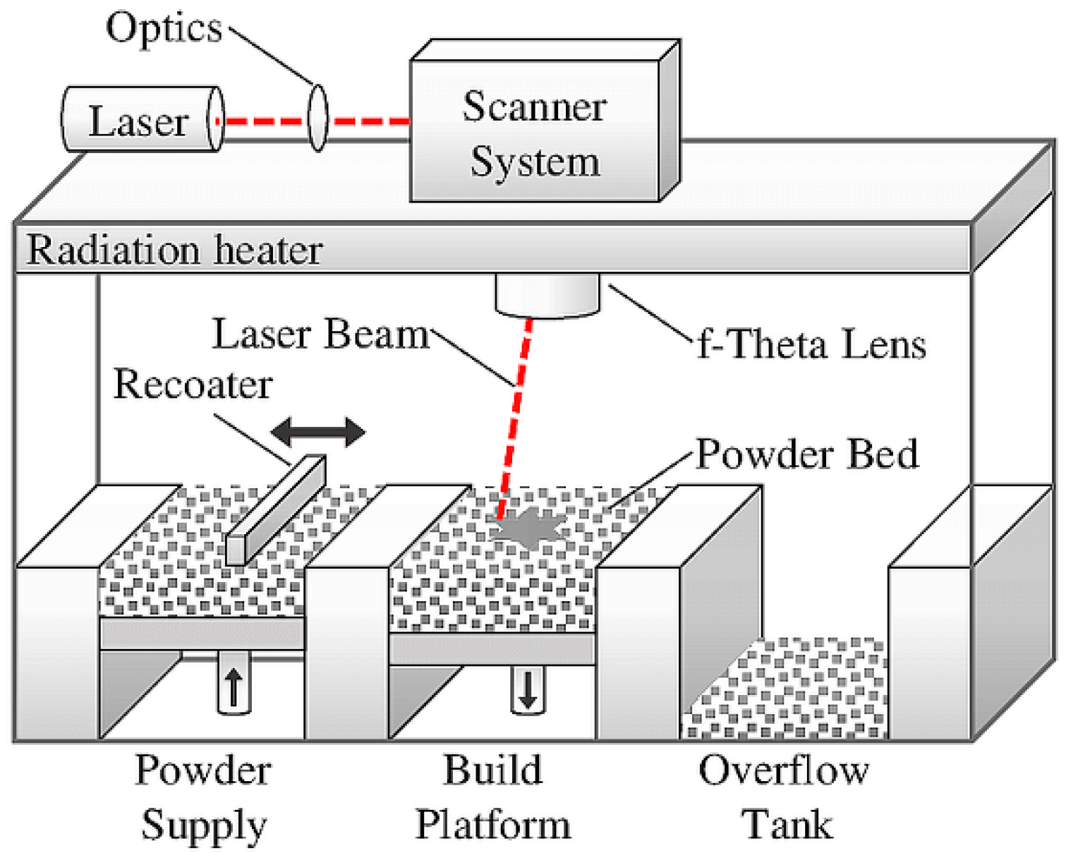
In terms of research and development, laser-based powder bed fusion of polymers (PBF-LB/P) has experienced significant growth over the last decade. In this selective laser sintering (SLS) process, a high energy laser merges material at selected areas on the powder bed surface. Heat treatment below the melting point leads to the formation and growth of sintering bridges between powder particles and densification of the material without liquefaction. After laser exposure and a period of cooling, a new layer of powder is applied by the coater and the build platform is lowered by the thickness of one layer. Constant continuation of these process segments enables the formation of solid and three-dimensional structures, enclosed by non-melted powder [10,11]. The schematic of the PBF-LB/P process is depicted in Figure 1.
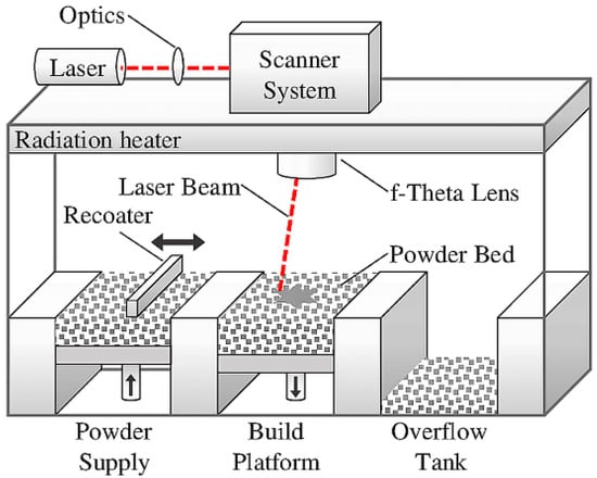
Figure 1.
The schematic of selective laser sintering [12].
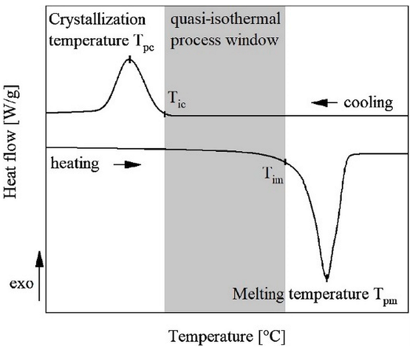
As described in [13,14], the processing temperature of semi-crystalline thermoplastics in PBF-LB/P is based on the model of isothermal laser sintering by differential scanning calorimetry (DSC) measurements. The DSC curve depicted in Figure 2 shows the heat flux contrasted with process temperature and thermal transitions of PA12 (PA2200, EOS GmbH).
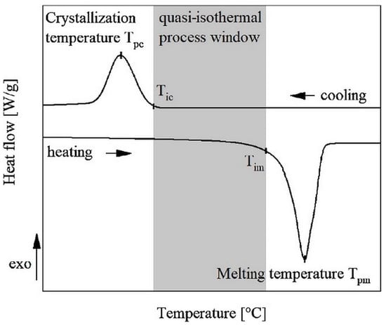
Figure 2.
DSC (differential scanning calorimetry) curve of melting and recrystallization process in selective laser sintering of PA12 [13].
As can be seen in Figure 2, the inside temperature of the building chamber has to exceed the recrystallization temperature and be lower than the temperature of melting . The simultaneous existence of a solid and molten state allows solidification without thermal distortion and thermal stress, due to the characteristics of an isothermal process. The molten state lasts until the building step’s completion and the subsequent recrystallization happens homogeneously due to the low cooling rate. Many factors, such as complex thermal interactions during the building step, the involvement of the continuously repeating sub-processes of powder coating, laser exposure, and consolidation affect the process of selective laser sintering [15]. Uncontrolled thermal interactions are especially likely to affect the workpiece’s properties, such as its dimensional accuracy, mechanical properties, and part density. Further investigations of temperature fields are required as part of process monitoring to understand thermal interactions, ensure part quality, and decrease the number of defects [16].
By meeting industrial requirements, the process of laser-based powder bed fusion of polymers (PBF-LB/P) has already broken through in certain fields. However, successful integration into the industrial process flow and into the supply chain is still challenged by the lack of sustainable process control [17]. Consistent process performance would require suitable in-process quality assurance measurements. Apart from the closed-loop control of the powder bed temperature monitoring, variable laser parameters, and the implementation of standard camera systems to detect major defects, such as part displacement, there are only scientific approaches for real-time and in situ process monitoring and no suitable solutions for industrial applications. The process flow by itself allows for remarkable possibilities in layer-by-layer monitoring for preventing defect transfer into final components and ensuring material properties and part quality [18]. The implementation of suitable online quality control is difficult to realize due to largely enclosed soft- and hardware solutions and the fact that almost no intrusion into parameters is possible during ongoing processes.
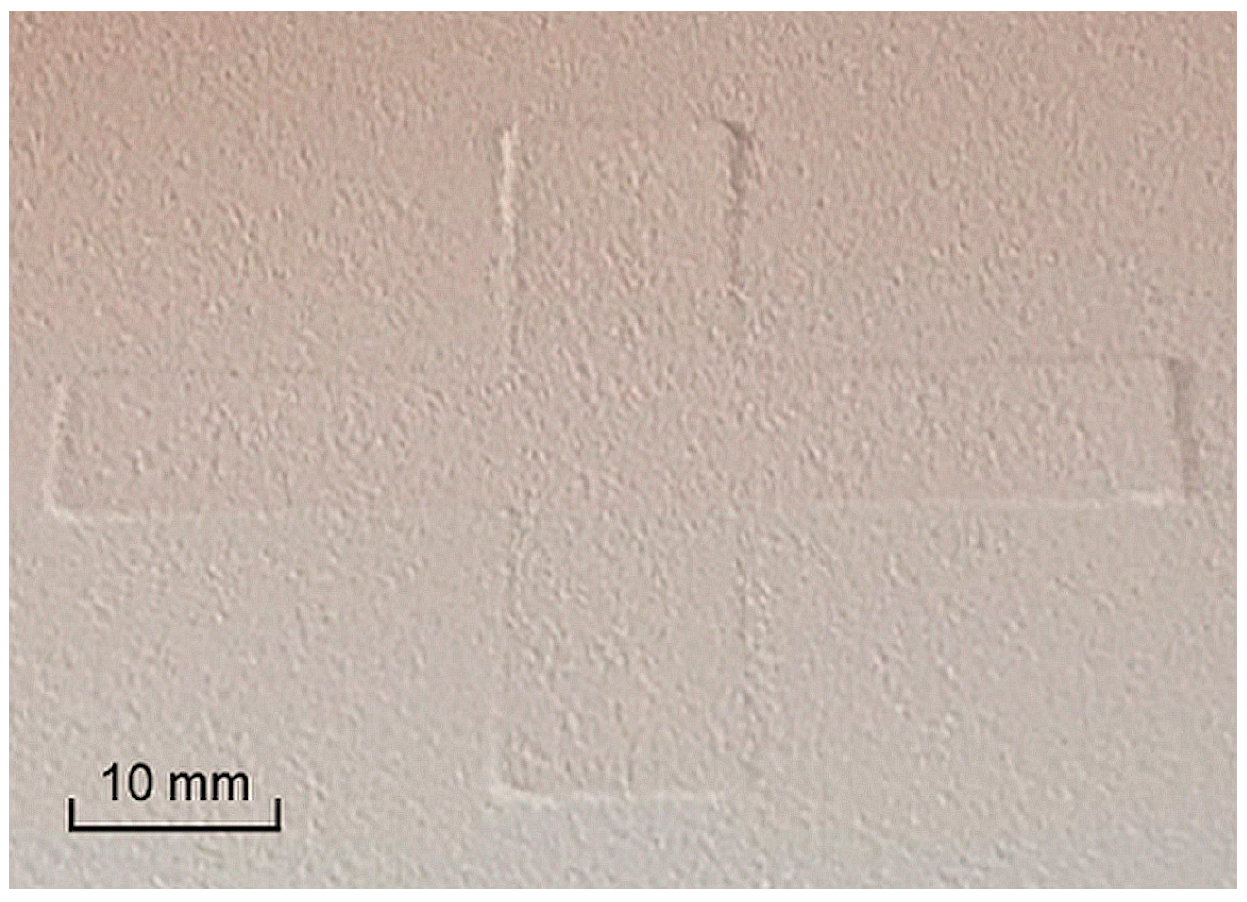
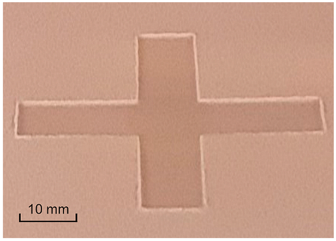
In this paper, a new approach of curling defect detection and analysis of powder bed structure in PBF-LB/P is proposed by the simultaneous application of industrial grade laser profilometry and thermal imaging. Curling, as an in-process phenomenon where mainly only the first layers of the part are affected, is caused by stress due to temperature gradients, resulting in lifting of the part from the powder bed. According to [18], “warpage” is defined as a “post-process” process that results in deformation of the entire part. If non-tempered powder is introduced after the laser exposure, uneven shrinkage between the top and bottom of the part induces a curved profile close to the free edges of build parts, as can be seen in Figure 3. The effect can occur on the surface after coating, after the laser exposure (as depicted in Figure 4), in-build during processing, or even when the process is finished, and the components are cooling down to room temperature [17].
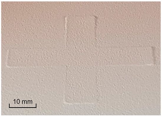
Figure 3.
Curling defect after coating a new layer of powder. Visible lifting of part segments from the powder bed.
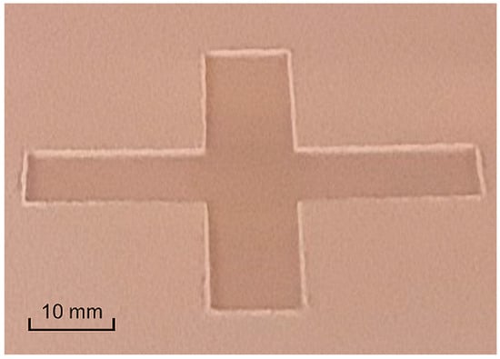
Figure 4.
Curling defect after laser exposure. Visible melting depth and curled peaks at free edges of cross part.
Previous scientific and experimental approaches for process control and defect detection in PBF-LB have revealed a wide range of relevant concepts addressing both polymer and metal powder-based fusion. Beside similar powder bed defects concerning both processes, such as coating failures, curling, shrinkage, part shifting, and powder short feed, PBF of metals (PBF-LB/M) might lead to additional defects such as spatters, porosity, and cracks due to process parameters such as temperature, laser power, and material properties [17,19,20,21,22]. As part of the literature research, previous works have been delineated into different research fields as sensor-only concepts applying a variety of measuring methods such as thermography, profilometry, and fringe projection to analyze powder bed quality, and additionally machine/deep learning approaches to defect detection and prediction.
To the best of our knowledge, the simultaneous application of laser profilometry and thermal imaging has not yet been discussed in powder bed fusion of polymers. Standalone laser profilometry solutions that have already been presented had limitations due to the mounting position within the installation space and the resulting detection range on the powder bed. The mounting position of both sensor concepts outside the installation space enables the sensing of the complete powder bed surface, providing real-time height data of curling failures and associated temperature fields at different stages of the ongoing manufacturing process. This new approach to monitoring the process in PBF-LB/P primarily focuses on revealing relationships between the spatial location of defects and the actual thermal distribution that leads to failures in these areas. This current work demonstrates a novel approach to real-time process monitoring and in situ defect detection in selective laser sintering of polymers by combining external laser profilometry to compile structural 3D data and thermal imaging to highlight the related thermal fields and temperature distributions. For the first time, these two sensor concepts have been successfully deployed in powder bed fusion of polymers to solve both the challenge of capturing the whole powder bed surface inside the installation space and of providing real-time data. The aim of this work was not the optimization of the process or part quality, but rather to demonstrate the functionality and fusion of different inspection methods to reconstruct the powder bed surface and monitor the process temperature in real time.
1.1. Previous Approaches of Process Monitoring by Thermal Imaging
In [23], Greiner et al. investigated the interaction of the material and laser beam in PBF-LB/P to enhance the reproducibility of part properties. Thermographic infrared measurements were made of the resulting temperature fields and the local temperature evolution in the xy-plane. In [24], Greiner and Drummer also analyzed the final and geometry-dependent part properties by investigating the exposure strategy, the consistence of the hatching strategy, the influence of laser power, and the scan speed. Various parameter strategies originating from laser beam melting of metals were evaluated to overcome the limitations of laser sintering of polymers by applying thermal infrared visualization. A direct correlation between the resulting temperature fields and part properties could be detected. Hofman and Wudy [25] investigated the influence of process parameters on melt pool temperatures in PBF-LB/P by evaluating temperatures during ongoing process steps. A continuous data stream containing thermal imaging was introduced to enable automated calculation of characteristic processing times and temperature fields. Decay values at different cooling rates were combined with process knowledge to differentiate process regimes. A further publication by Phillips et al. [26] also revealed the efficacy of using thermal imaging in process monitoring the PBF-LB/P process by investigating a complementary approach of actively controlling the parameters of the laser to reduce thermal fluctuations on the powder bed surface. A high level of control over final part properties was achieved by controlling the level of energy input at the laser exposure. Another approach of actively controlling the input of laser power in PBF-LB/P by using a high-speed mid-wave infrared (MWIR) camera was presented by Zhang et al. [27]. An automated laser control system was proposed in the paper to eliminate thermal gradients in the post-sintering temperature by adjusting the laser power according to pre-sintering temperatures. In their study [28], Walker Wroe et al. established an approach of verifying part quality in real time by recording thermal histories of manufactured layers and comparing them to the ultimate tensile strength (UTS) of tested parts in the shape of bars. A further attempt was made by identifying the position of fracture based on the thermal imaging history. An early approach by Wegner and Witt [29] examined the effective integration of a thermal imaging system into a laser sintering machine to measure irregularities of radiant heater temperatures and the effects on temperature distribution on the powder bed surface. Further influence factors on the homogeneity of the surface temperature were analyzed.
1.2. Previous Approaches of Defect Detection by Measuring the Powder Bed Surface
Several scientific approaches address sensor-only concepts of measuring the powder bed surface in PBF-LB/P by generating 3D data as part of laser profilometry and fringe projection, as well as optical coherence tomography (OCT), contact image sensor (CIS) application, and microscopy. In [17], Sillani et al. managed to successfully integrate a laser profilometry system by Keyence (Osaka, Japan) into a DTM Sinterstation 2000 using Duraform P12 powder material. The profilometer was mounted at the coating system and required cooling due to temperatures of up to 170 °C. Within the paper, several issues were investigated, such as measuring the powder layer quality in different conditions, highlighting the impacts of adapting the recoating speed, preheating temperature, and particle shape. This approach enabled the calculation of the effective layer thickness (ELT), the evaluation of layer density, and the measurement of curling from 70 µm to 350 µm. Although the work showed an effective way of in situ process monitoring in PBF-LB/P by detecting geometrical variations with sub-micrometer vertical resolution, only sub-areas of the powder bed could be observed due to the scanning range of the profilometer and the mounting position. Further, no coherences were investigated in terms of thermal fields and temperature distributions on the powder bed surface, leading to defects such as curling. Considering the results presented in [30] by Borish et al., a laser profilometry sensor and a thermal camera were installed at a fused deposition modelling (FDM) system. By automated adjustment of material flow and build speed, three types of defects were mitigated: low layer times, underfill, and overfill. The control system handled the build parameters to compensate for height deviations from −100% underfill to 50% overfill and low layer times of 15 s. No detailed information about the profilometer or thermal camera system was given. Southon et al. [31] introduced a further approach for curling defect analysis in PBF-LB/P by investigating the feasibility of deploying a fringe projection system to measure the powder bed surface of an EOS P100 PBF-LB/P machine. The sensor was mounted outside the machine. This enabled large areas of the powder bed to be covered with an xyz resolution of 75 µm. In this approach, an effective method was presented of controlling curling defects by tuning process parameters. A lack of information on data acquisition time and surface data analysis raised questions regarding implementation as a real-time process monitoring system. In [32], Gardner et al. investigated the influence of varying laser power on the penetration depth in selective laser sintering by applying optical coherence tomography (OCT). OCT enables subsurface imaging and defect detection based on low coherence interferometry by encoding wavelength depth information with an axial resolution of between 1 µm and 20 µm. The aim of this paper was not the implementation of a real-time monitoring system, but rather on observing subsurface melt pool changes and defects such as increasing melt pool depth due to excessive laser power. A further approach to surface texture analysis and subsurface defect detection in PBF-LB/P by using OCT was presented by Guan et al. in [33]. A spectral domain phase-sensitive OCT system (PhS-OCT) was used to quantify simulated defective regions with graduated porosity embedded in fully dense regions. Loose powder detection and differentiation between densities of at a sub-surface depth of 350 µm was achieved. Further optical measurements by focus variation microscopy (FVM) were implemented to compare the ability of OCT to detect surface profile and areal texture with that of FVM. A simple and cost-efficient solution of scanning the powder bed surface in PBF-LB/P was presented by Phuc and Seita [34]. Within this approach, a contact image sensor (CIS) taken from a flatbed document scanner was mounted on the powder re-coater to assess powder bed defects in high-resolution and with a large field-of-view. Non-uniformities were detected by quantifying the out-of-focus regions using numerical image analysis techniques, achieving a spatial resolution of ~5 µm. Sassaman et al. [35] proposed an approach of studying the characteristics of the melt pool during and after laser exposure in PBF-LB/P. A sensor system was designed and successfully implemented into a custom PBF-LB/P machine, known as the Laser Additive Manufacturing Pilot System (LAMPS) [36], which is located at The University of Texas, Austin. The system was designed to operate under manufacturing process conditions, performing in situ microscopy to highlight particle-scale dynamics at realistic scan speeds and temperatures. The experimental setup included different sub-units, including a high-speed camera for the requisite scale imaging, an adjustable zoom lens to capture the required spatial resolution, and the illumination. The results revealed a particle rearrangement occurring over an extended time of ~10 ms after laser exposure at a particular location. Although the studies summarized here demonstrate effective sensing of the powder bed surface, the methods presented still reveal limitations due to limited coverage, the complexity of system implementation, or the lack of additional data such as temperature fields to assess the formation of defects, such as curling on the powder bed.
1.3. Defect Detection and Prediction by the Application of Deep Learning
The use of artificial intelligence, particularly deep-learning algorithms, to detect or predict processing errors has already been scientifically investigated in several places. Deep Learning (DL) has become one of the most widely used computational approaches in machine learning (ML) and achieves excellent results at a variety of complex computer vision tasks [37]. The following approaches address the ability of implementing DL into data analysis to detect and even predict failures in powder bed fusion of polymers. A previously published work revealed reproducible results in curling defect detection by thermal imaging and convolutional neural networks (CNN) [38]. Curling defects were manually induced by adjusting certain process parameters, and thermography was used to highlight related temperature distributions. The extracted frames of accurate and defective processes served as a basis to train a number of CNNs. The CNN achieved an average curling defect detection accuracy of 98.54%. According to [18], Westphal and Seitz attained similar accuracy results of 95.8% using the VGG16 CNN and recordings by a simple high-definition camera system. Various powder bed defects were analyzed and predicted by the CNN. A further approach of detecting powder bed defects in PBF-LB/P by applying a digital camera system and deep residual neural networks was suggested by Xiao et al. [39]. Three different powder bed defects, curling, part shifting, and powder short feed, were artificially generated by varying the process conditions, using two different PBF-LB/P powder types. This method exhibited high accuracy rates of up to 96% in defect detection and was able to cope with image blurring and geometrical distortion. In [40], an AI-driven approach of using automated build part characterization to detect and forecast printing errors in PBF-LB/P was presented by Bauer et al. To investigate the problem of error prediction, a combined method of unsupervised pseudo-labelling (autoencoder-based clustering) and supervised deep learning (ResNet50) was applied. Based on grayscale-camera pictures, an error detection accuracy of more than 93% was achieved. Using the cox proportional hazards (CPH) model to predict the remaining time until error, statistically significant forecasts (p < 0.005) of the remaining build time without failure were achieved.
Beside the practical approaches of process monitoring and defect detection in powder bed fusion of polymers summarized here, further sensor concepts such as inline coherent imaging [41], enhanced phase measuring profilometry [42], multi sensor fusion [43,44], and acoustic approaches [45] were investigated for selective laser melting of metals (PBF-LB/M). The application of DL provides an effective method of monitoring the process of powder bed fusion of polymers. However, the images used to train and evaluate a CNN require a very large amount of data and preparation is necessary to achieve the above results. Alternative data as provided by laser profilometry has not yet been processed by DL. The approaches outlined here clearly demonstrate the effective use of thermal imaging in PBF-LB/P in terms of part properties, in situ process control, and further analysis of process steps, but the data acquired does not allow direct correlation with geometric height values. The actual detection of curling errors using thermal imaging technology was not part of the investigations presented and has not been able to be realized so far due to a lack of 3D information. Additional measurement methods, such as laser profilometry, are required to verify the suspected failures at the powder bed.
2. Materials and Methods
2.1. PBF-LB/P System and Build Part Setup
An EOS Formiga P 110 selective laser sintering machine was used to perform the experimental trials during this work. The PBF-LB/P system uses a CO2 laser with 30 W of output power and a wavelength of 10.6 µm to merge powder particles at the powder bed. PA12 (PA 2200) was used as high-performance nylon throughout this study. The system is capable of scanning speeds of up to 5 m/s within an exposed area (xy) of 200 mm × 250 mm, merging a minimum of 50 µm and a maximum of 200 µm layer thickness. The maximum build part height (z) is 330 mm. The parameter setup included a layer thickness of 100 µm and standardized non-adapted laser scan speed and hatch spacing by the EOS default exposure strategy. To ensure a constant process temperature according to the DSC curve, the process chambers at the upper installation space and lower unloading chamber are both heated by separate built-in process heaters.
To create artificial curling defects, the default process temperature of 167 °C was manually reduced. A reduction of 3% to 162 °C revealed the first distortion effects. In addition, the intensity could then be slightly increased by manually interrupting the process and thus extending the layer cooling time. Further parameter adjustments during the ongoing sintering process are prevented by limited access to the operating software. As can be seen in Figure 5, a series of calibration parts were manufactured to define parameter settings as a basis for subsequent analysis. Figure 5 illustrates the visible appearance of distortion of the whole component (b) at the test geometry (a) compared to an accurate test part without visible warpage (c).

Figure 5.
Comparison of a defective test part (a) and an accurate test part (c). Clear appearance of distortion caused by continuous curling during the process (b) at the free edges after systematic reduction of the process temperature to 162 °C.
After the definition of parameters, several test part geometries were defined as depicted in Figure 6a. The build parts taken as bases for further triangulation and thermal analysis contained cross-, triangular-, and circular-shaped geometries with outline measurements of 50 mm. The parts contained 6 identical stacked layers measuring 2 mm of material thickness for each layer, separated by a gap of 0.4 mm and connected by a central cylindrical pin of 8 mm in diameter as shown in Figure 6b. The total height of each part measured 14 mm. Stacking identical layers enabled systematic iterations of curling analysis without the in-between waiting time of process restart and heating phases.

Figure 6.
Different test parts in (a) as bases for further triangulation and thermal analysis: cross-, triangular-, and circular-shaped geometries and in (b) 6 identical stacked layers of 2 mm material thickness and a total height of 14 mm.
2.2. Evaluation of Powder Bed Temperature by Thermal Imaging
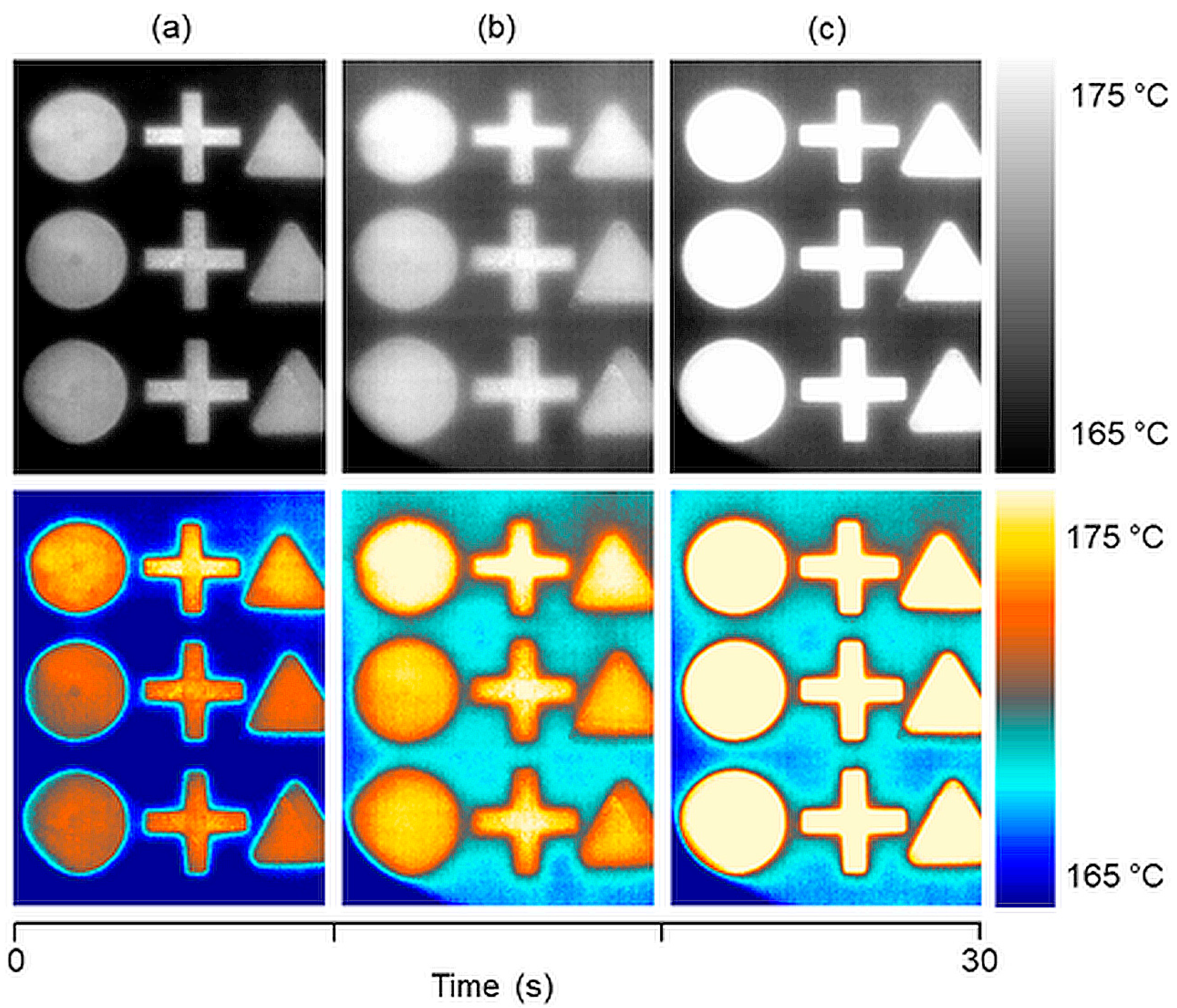
To capture the temperature distribution on the powder bed surface of the PBF-LB/P system, a FLIR T420 infrared camera was employed. The camera provides real-time thermal imaging with a resolution of 320 × 240 pixels, 30 frames per second, and a 25° field of view. The installation outside the process chamber was inevitable due to a variety of reasons such as camera dimensions, a minimum focus distance of 400 mm, and process temperature. To capture the whole powder bed surface at the installation space, to prevent geometrical distortions, and in consideration of the parameters mentioned above, the camera was centrally mounted at the top inspection window of the PBF-LB/P system. Separation of the camera and the actual installation space was realized by installing a calcium fluoride (CaF2) optical window. In the actual spectral range, the transmittance of CaF2 is more than 90%. To prevent coating effects at the optical window caused by vaporizing powder particles during laser exposure, a nitrogen (N2) flushing was implemented by branching a separate conduction at the integrated nitrogen generator. The calibration of the emissivity of PA12 powder was performed by aligning the temperature value at the inbuilt pyrometer and the value at thermal imaging. According to [8], an emissivity of 0.85 was defined for PA12, confirming correct temperature values. The temperature values are not quantitatively determinable during phase transition between powder, solid, and molten material due to a significant change of emissivity [46]. Figure 7 shows the thermal grayscale imaging and the related color map of the test geometries on the powder bed after coating (a), surface heating time (b), and after laser exposure (c), leading to no induced curling at the current process stages. As can be seen in Figure 7, only small areas have been cut off the edges of thermal recordings, referable to the field of view and shadowing by the inspection window of the PBF-LB/P system (shading at left bottom part of images).
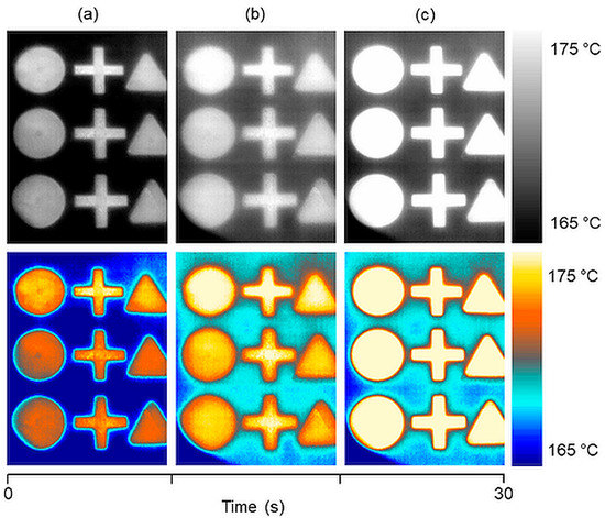
Figure 7.
Thermal grayscale imaging (top) and related color map (bottom) of the powder bed surface temperature distribution at certain process steps: (a) after coating a new layer of powder, (b) after surface heating time, and (c) after laser exposure. Clear visibility of pre-sintered areas through new-coated layer of powder (a,b), no visible defects on powder bed surface.
Within this work, different color maps have been studied on thermal recordings to convert single value grayscale images, since the human eye is not very sensitive to small changes in grayscale intensities. According to related temperature fields, different color maps and temperature ranges showed clear differences in the visualization of details on the powder bed surface. The color map shown in Figure 7 was used from then on for further analysis.
2.3. Implementation of Laser Profilometry and Sensor Movement
In this current study, a Keyence LJ-X8400 (Osaka, Japan) industrial grade laser profilometry system, including a LJ-X8000E control unit, was mounted outside the installation space, linearly translated alongside the process window by a linear unit. To avoid image distortions, the curved protective plastic window of the EOS machine was removed. The remaining planar laser protection glass was dimensioned for wavelengths of 10.20–10.80 µm, leading to no interferences in the linear profilometry laser that operates at a wavelength of 405 nm. Pre-investigations revealed no influence on the profilometry results by the laser protection glass.
Mounting the profilometry sensor outside the installation space at a certain distance led to two main advantages: no cooling is required, and the complete powder bed surface can be captured in the x- and y-directions. The extended distance to the powder bed surface leads to a reduction in resolution in the y-direction, but this was regarded as negligible due to the focus on vertical absolute data. Encoding was realized by the linear unit, resulting in 25,000 profile steps due to a powder bed width of 250 mm and an encoder resolution of 10 µm (x). The laser profilometry system provides a vertical resolution of 5 µm according to data sheet [47]. Further parameters of the laser profilometer are summarized in Table 1.

Table 1.
Parameters of Keyence LJ-X8400 laser profilometer.
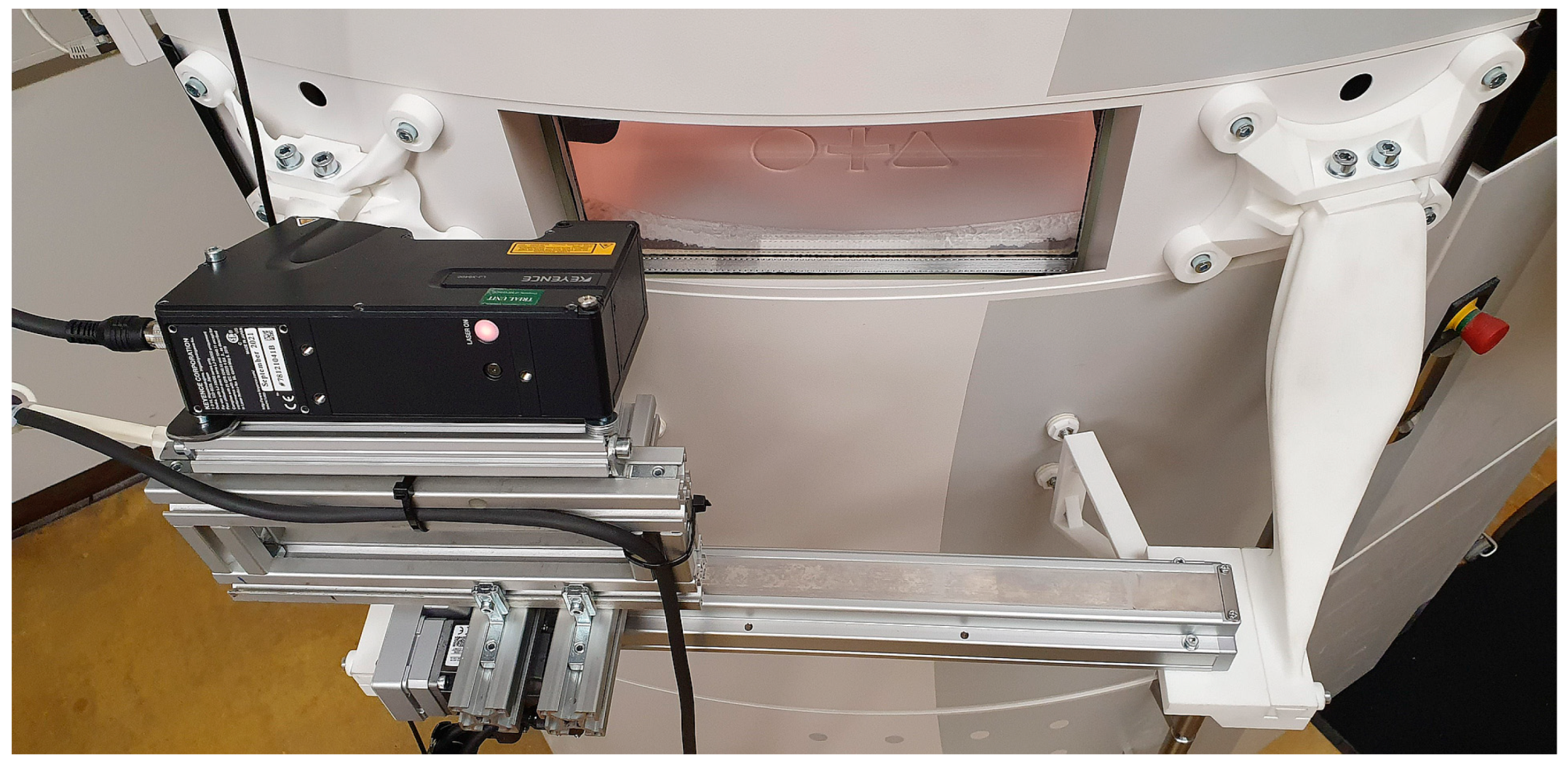
Since no CAD data is available, a specific reconstruction of the outer shell of the PBF-LB/P machine and proper fittings were necessary to mount the laser triangulation system, as can be seen in Figure 8. Further adaptations of the EOS system were made by implementing mechanical end-switches at the coater to synchronize sensor movement of the linear unit at the deployed SPS.
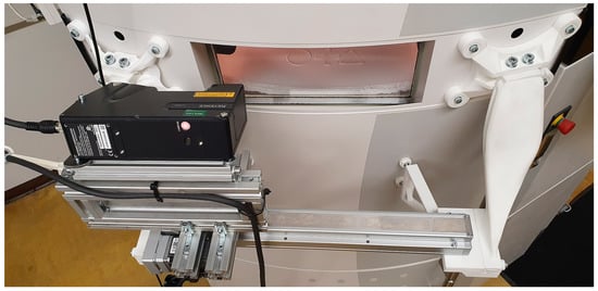
Figure 8.
Mounting of the laser triangulation system at the EOS Formiga P 110. The triangulation system was mounted on the linear unit to enable linear translation alongside the laser protection glass and to capture the complete powder bed surface inside the installation space.
2.4. Calibration of the Laser Profilometer
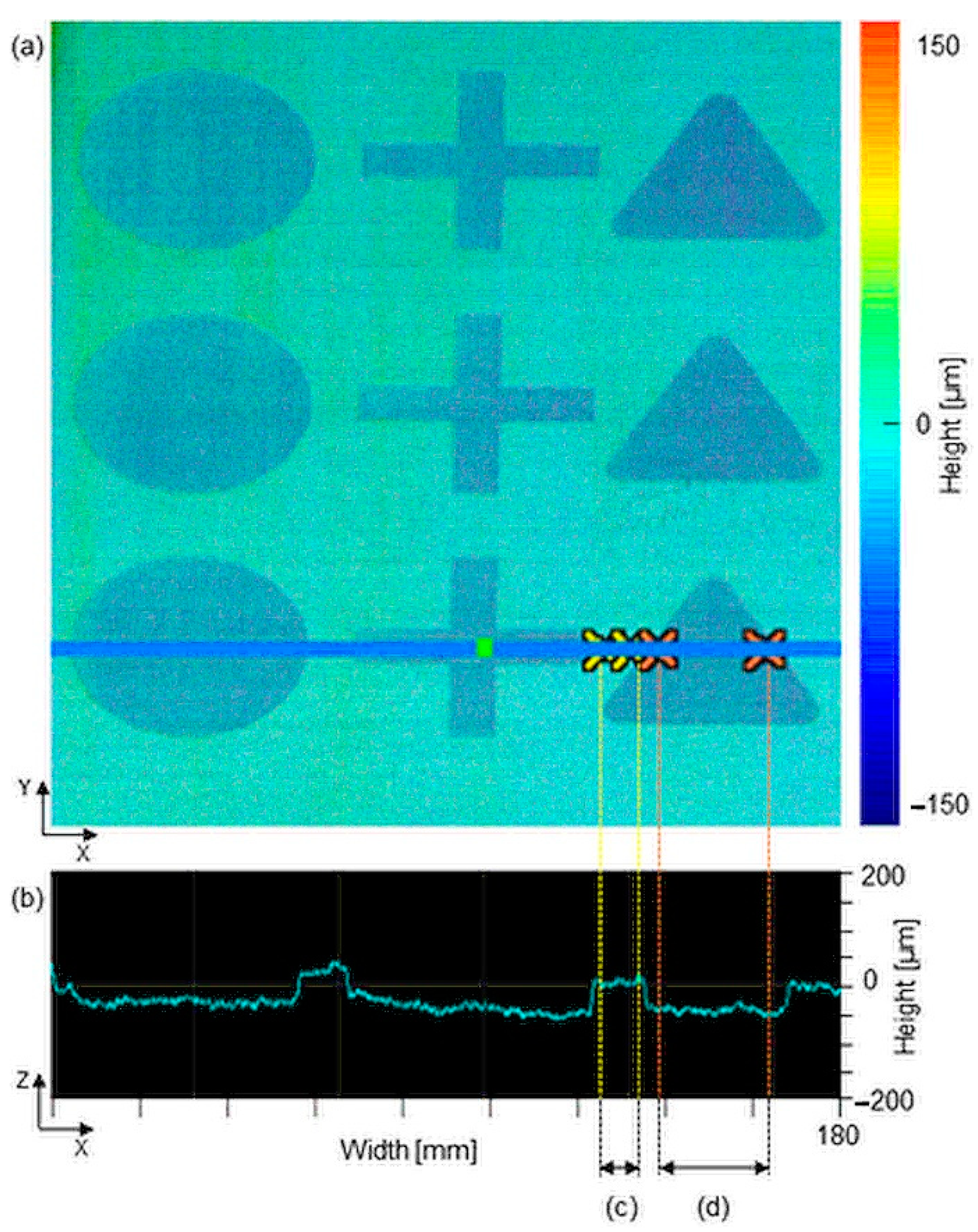
The proper mounting and calibration of the profilometry system forms the basis for metrological properties and reproducible measurements. The calibration was done by defining and implementing a constant horizontal zero plane using reference measurements inside the installation space. To capture the complete installation space, the sensor had to be inclined by 67° in relation to the normal vector of the powder bed surface. The inclination of the sensor had to be corrected manually via the Keyence’s evaluation software since automatic inclination correction is only provided up to an angle of 45°. This was done by manually defining the zero-level in relation to the sensor inclination. In order to ensure process conditions during the calibration, a powder coating of Nx layers was applied inside the process chamber to achieve an identical level of production. The surface of the powder bed surface was defined as the zero level for all subsequent measurements. Sintered components were excluded from the calibration by manually masking exposed areas to avoid zero level shift due to the melting depth. The measured value correction is based on a two-point principle by multiplying the resulting height values by a coefficient. Two measuring points are considered as a reference, and associated height values are given before and after the correction. The evaluation software calculates the correction for the entire range of measuring by interpolation. At the beginning of each iteration, the melting depth was defined as the reference and calibration point, which according to EOS GmbH is on average 50% of the layer thickness, in order to obtain reproducible measurements and to ensure error-free calibration of the laser profilometer. As can be seen in Figure 9, an average value of 54 µm was detected at the melting depth during calibration after laser exposure, which confirms correct calibration. Figure 9a shows the complete topology of the surface in powder bed fusion of polymers for the first time.
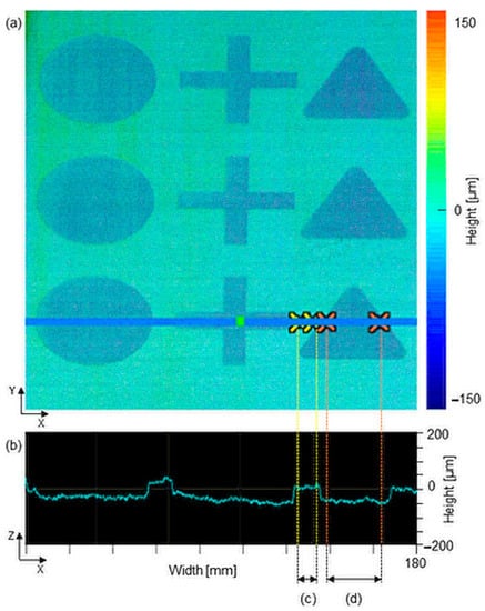
Figure 9.
Topology of the complete powder bed surface after laser exposure (a). The profile section of the melting depth (b) results in a height difference of 54 µm between an average value of the powder bed (c) and an average value of the melting depth at the triangular shaped build part (d).
In addition to the correct positioning and calibration of the profilometry system, the compensation of performance errors is crucial. When capturing 3D images from individual 2D profiles, even minimal vibrations of the linear unit lead to distorted measurement results due to the high resolution of the sensor. To compensate for deviations and guarantee the quality of the output results, a noise filter was applied to remove irregularities from topological data and provide an additional correction function for profile orientation. The noise filter detects peak values and replaces them with values of neighboring measurement points when there is a sudden increase of more than 100 µm compared to the neighboring point. The correction function for profile orientation levels deviates of the 2D profile in the x-, y- and z-directions.
3. Results
3.1. Thermal Visibility of Curling Defects on the Powder Bed Surface
Revealing the relationship between the thermal distribution and curling defects on the surface of the powder bed was one of the main research aims of this study. Curling, as the thermally induced in-process distortion of the free edges of build parts, is still one of the challenges in the additive manufacturing of polymers. Considering that productivity and efficiency are key aspects in AM, the reduction of single-layer build time by optimizing process parameters enhances the further potential prospects of this technology. Nominal layer build time correlates directly to the processing steps such as heating, laser exposure, layer cooling, and recoating. According to the scan strategy, the laser exposure time is primarily influenced by the part bed size and varies with the complexity of the part. The duration of heating is related to the powder’s properties and mainly influenced by the thermal conductivity of the powder deployed, while recoating time depends on spreader speed and geometry [17].
Utilizing the above-mentioned process parameters, a reproducible approach of artificially generated curling was employed as part of this study. Curling, as described by Mercelis and Kruth in [48] and Soe in [20], is generally defined as the in-process lifting of the free edges of a component due to divergent shrinkage and associated residual stresses between the top and bottom of the component. This phenomenon is suspected to develop when the surface of a sintered layer is exposed to a new layer of coated powder due to heat transferring by conduction, or by heat transfer to the surrounding circulating gas by convection and radiation [49]. The temperature drop at the surface induces shrinkage at the top, while the bottom surface is kept below the higher temperature powder bed surface. In addition to other related process factors for curling, such as scanning strategy, laser power, part dimensions, and location/orientation, the curling effect is highly related to time and temperature during process, according to the elementary principles of heat transfer. As described in Section 2.1, both process parameters, time and temperature, were iteratively adjusted until constant and reproducible process conditions prevailed. Under set conditions, the visible appearance of curling was investigated within two different process stages, after recoating and after laser exposure during layer cooling time, revealing interesting new effects.
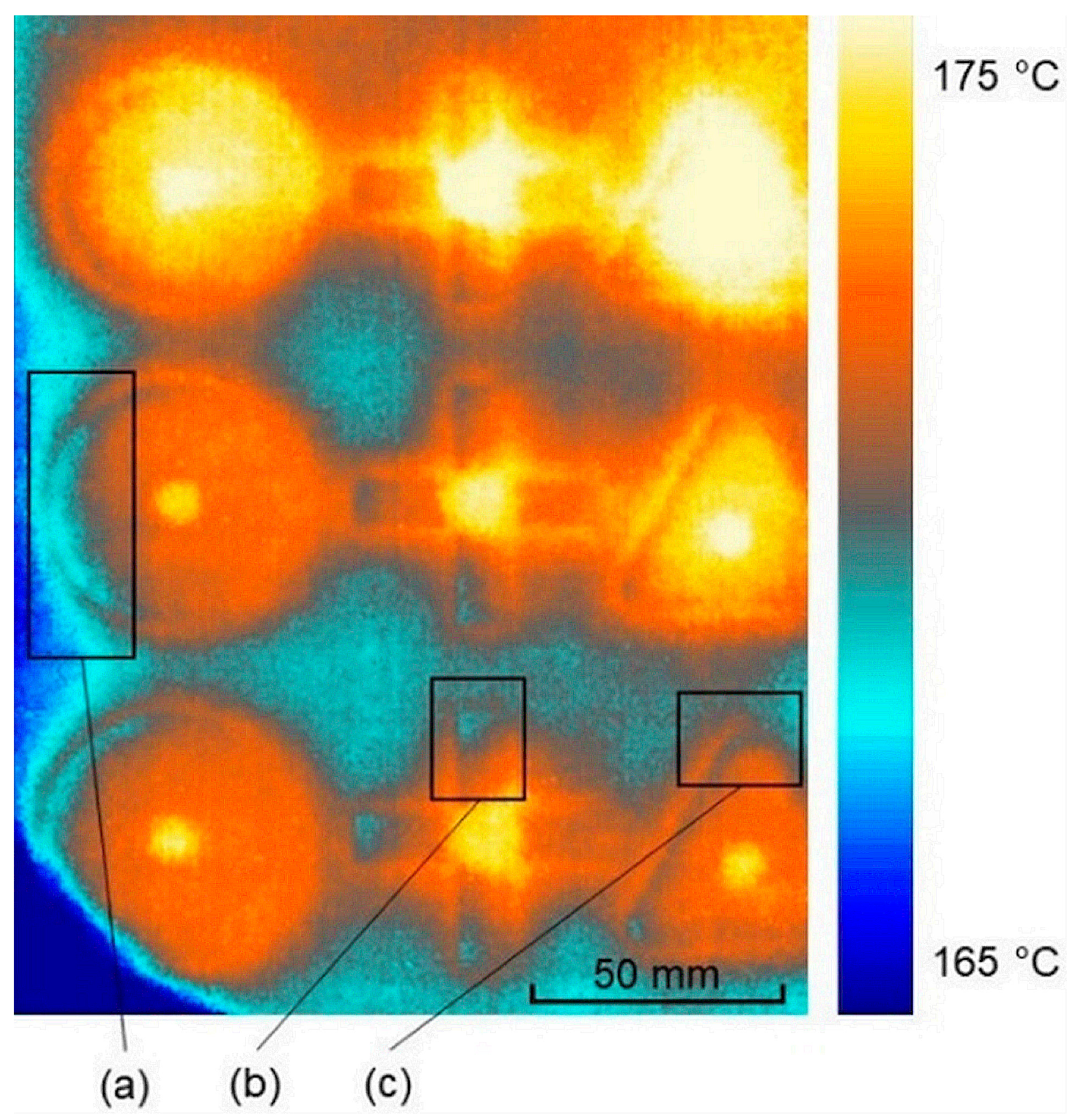
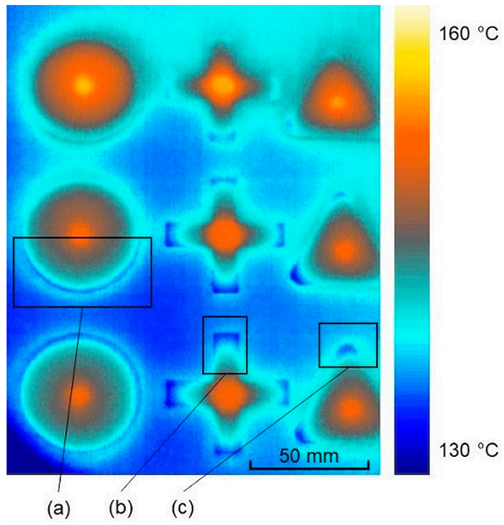
As can be seen in Figure 10, the curling effect gets clearly visible at the thermal image after recoating with a new layer of powder. Sections close to the free edges of all depicted build part geometries (a–c) occurred in distinct highlighted temperature changes compared to the rest of the geometry. The visibility arose because the temperature of the curled edges very quickly took on the manually pre-lowered temperature of the circulating surrounding gas, due to the combination of the effects related in the section above: heat transfer by conduction into a new layer of powder and by convection and radiation into the surrounding gas. In addition to lowering the process temperature, the layer cooling time was extended (>100%) to provoke the appearance of curling.
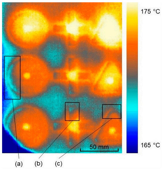
Figure 10.
Thermal visibility of curling phenomenon during process after coating. Distinct lifting of the free edges of (a) circular, (b) cross, and (c) triangular-shaped build parts and lower intensity of curling at the top of the powder bed due to less temperature variation.
3.2. Visible Effects of Solidification on the Thermal Conductivity of PA12
A further effect has been ascertained by considering the visibility of curling of non-coated areas on the powder bed. After laser exposure, the lifting was clearly visible to the human eye and is further demonstrated in Section 3.3 by laser triangulation, but the thermal images showed no visible curling compared to the images after powder recoating, as depicted in Figure 11a.

Figure 11.
The progression of the temperature distribution on the powder bed surface (a) after laser exposure and extended layer cooling time (no visible curling, faded transitions of the build part and powder bed due to temperature alignment), and (b–e) after recoating at a time step of 8 s (clear, visible appearance of curling).
The differences in visibility may be caused by the insulating effect of a new layer of colder powder, in addition to a change in the material density of PA12 due to the phase transition of powder state (ρ = 0.43 g/cm3) to solid state (ρ = 0.95 g/cm3) [50]. The densification process affects both material properties of PA12: the thermal conductivity (λ = 0.136 W/mK at sintered parts) and the specific heat capacity (cp = 2.35 J/gK at sintered parts) [50]. It takes longer for the curled areas of build parts to reach the temperature of the surrounding gas and become visible on thermal images. In order to underline this fact, the layer cooling time was further extended by prematurely terminating the process without significant upper insulation layers of unconsolidated powder. As depicted in Figure 12, clearly visible curling effects occurred close to the free edges of the components (a–c), but in a significantly lower temperature range than after the recoating process step, as depicted in Figure 10 in Section 3.1.
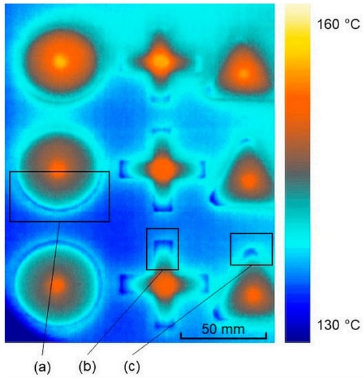
Figure 12.
First thermal visibility of the curling phenomenon at non-coated build parts (a–c). The premature process termination enabled cooling down of the build job without significant upper insulation layers. Curling finally appeared due to delayed heat transfer of sintered build parts into the surrounding gas.
The results showed clear visibility of curling defects in powder bed fusion of polymers using thermal imaging for the first time by narrowing the temperature range at the output software and evaluating different color maps. The assumption was confirmed that the solidification of PA12 powder affects thermal conductivity and thus delays the visible appearance of curling defects in thermal images. The additional laser profilometry system will provide structural 3D data to confirm the quantifiable height of curling defects appearing in the powder bed at both process steps, after laser exposure and after recoating with a new layer of powder.
3.3. 3D Topology and Related Temperature Distribution on the Powder Bed Surface
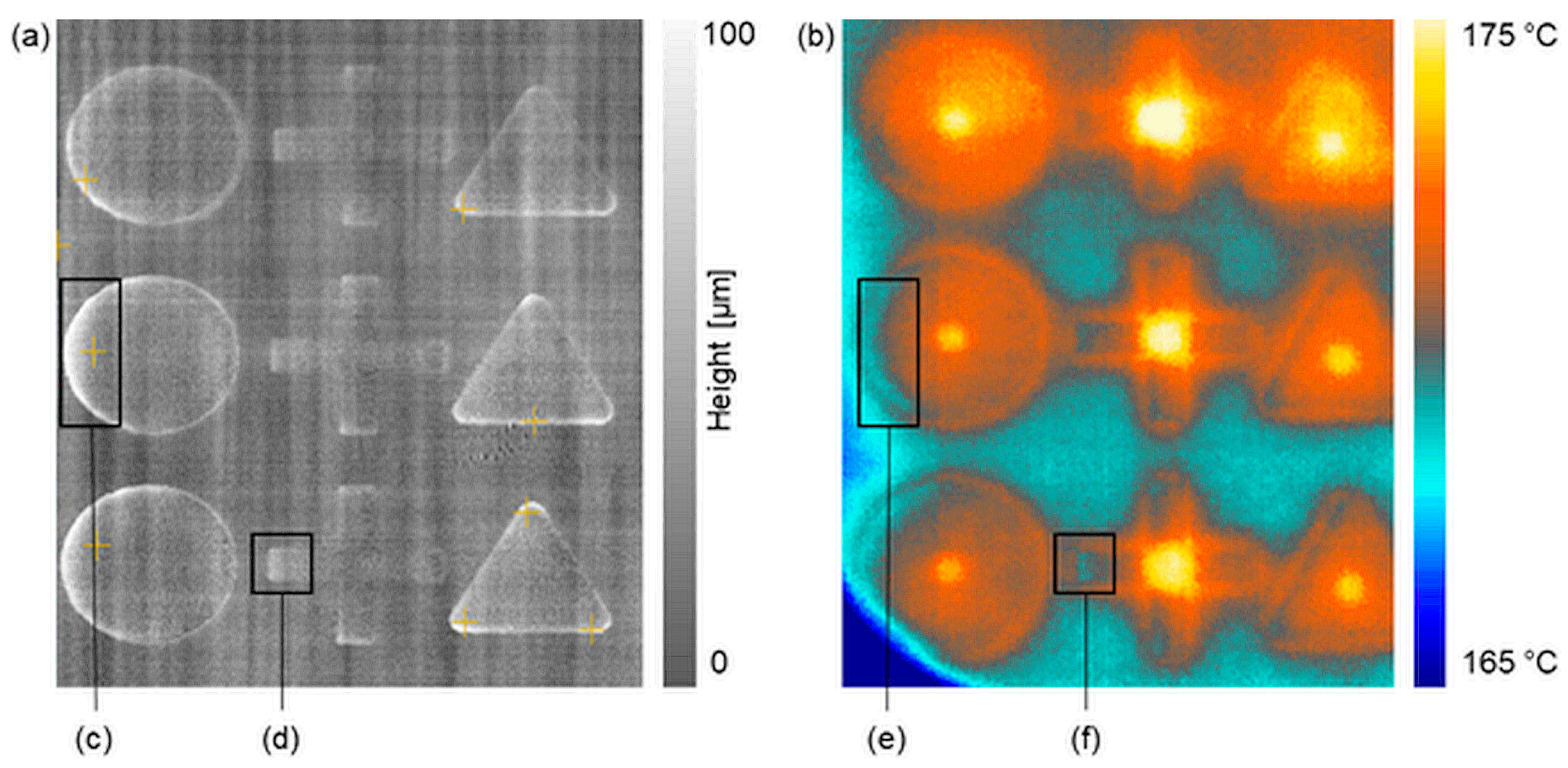
In order to obtain constant measurement results, a reproducible reference method was defined for each evaluation process. The surface data was generated by 3D topology, contrast shape detection, and grayscale visualization. It was referenced throughout the manually defined zero plane at the top surface of the powder bed. By manually defining and referencing the zero plane, deviations due to inclination of the profilometry system could be avoided. The 3D topology provides structural data of the current process quality by lining up 2-dimensional profile sections to generate a height map of the powder bed surface. In addition, maximum height values in the positive z-direction are automatically tagged by the system, enabling real-time process monitoring by adjusting process parameters if the defined threshold for curling defects is exceeded. The powder bed surface was measured simultaneously by laser triangulation and thermal imaging 12 s after recoating in an ongoing process when curling was visible to the human eye. The process temperature in the installation space and the cooling time of the previous layer were manually adjusted according to Section 2.1. Considering the thermal recording in Figure 13b, and as described in Section 3.1, lower temperatures were suspected as an indication of curling at build part sections, compared to the surrounding temperature distribution. The evaluation of the height map generated by the laser profilometer, as seen in Figure 13a, clearly proves that actual curling occurred at values of up to 80 µm (c) and thus, thermal imaging is capable of curling detection in powder bed fusion of polymers. The height map is based on grayscale imaging, highlighting sections of the components lifting up from the surface of the powder bed.
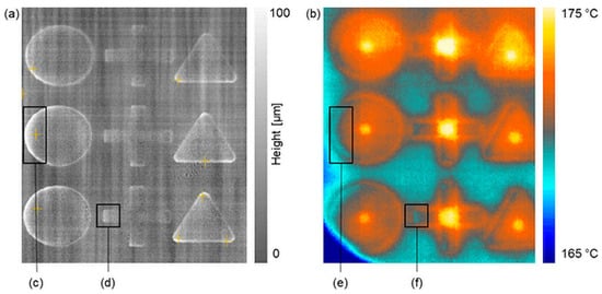
Figure 13.
Grayscale height map of the powder bed surface (a) after recoating. Related temperature distribution (b). Clearly visible coherences of the measured curling height (c,d) and temperature fields at the free edges of build parts (e,f). Slight visibility of striping at the 3D topology (a) due to non-filtered vibrations by the linear unit.
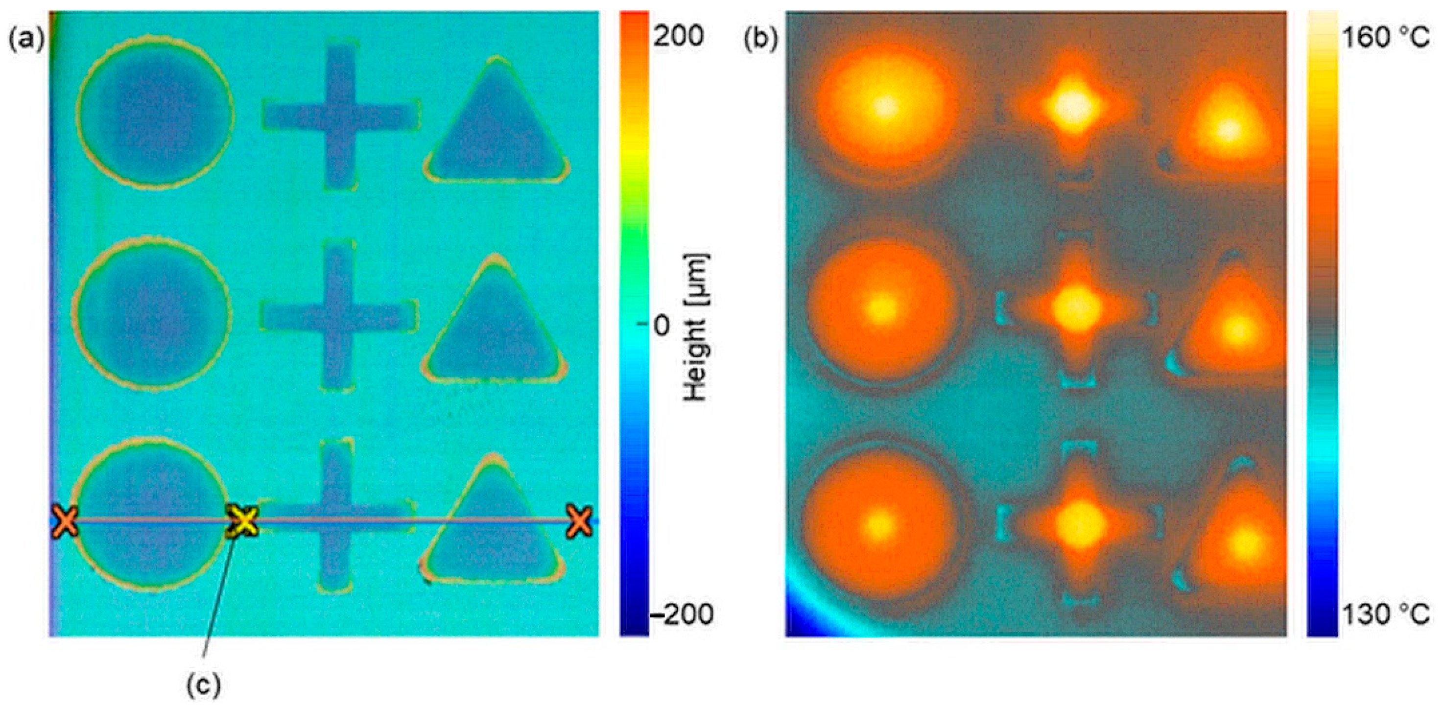
Iteratively generated height maps at different post-coating progressions revealed curling failure starting at 23 μm in an average range over the entire powder bed surface. In addition to the post-coating measurements, further height maps and related thermal images were evaluated after laser exposure to confirm that curling can occur in every process step, even in addition to the visible melting depth at the pre-coating state after laser exposure. Since grayscale images only highlight topologies in the positive z-direction, an alternative height map was applied (as previously seen in Figure 9) to reveal both positive and negative values relating to the zero plane at the powder bed surface. Regarding the 3D topology in Figure 14a, a clear expression of curling appears close to the free edges at almost every transition point from sintered areas to the powder bed surface. In Figure 14b, the related temperature distribution at the pre-coating state is shown, revealing similar expressions of curling as within the post-coating state in Figure 13b.
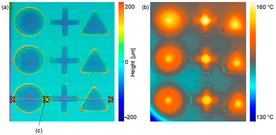
Figure 14.
3D topology of the powder bed surface (a) after laser exposure and related temperature distribution (b). A clear development of curling failure can be seen at the height map and the thermal image, even at the uncoated process state. Tagged line (c) as horizontal reference point for profile measurements to be discussed in Section 3.4.
3.4. Effective Curling Height at Profile Sections of 3D Topology
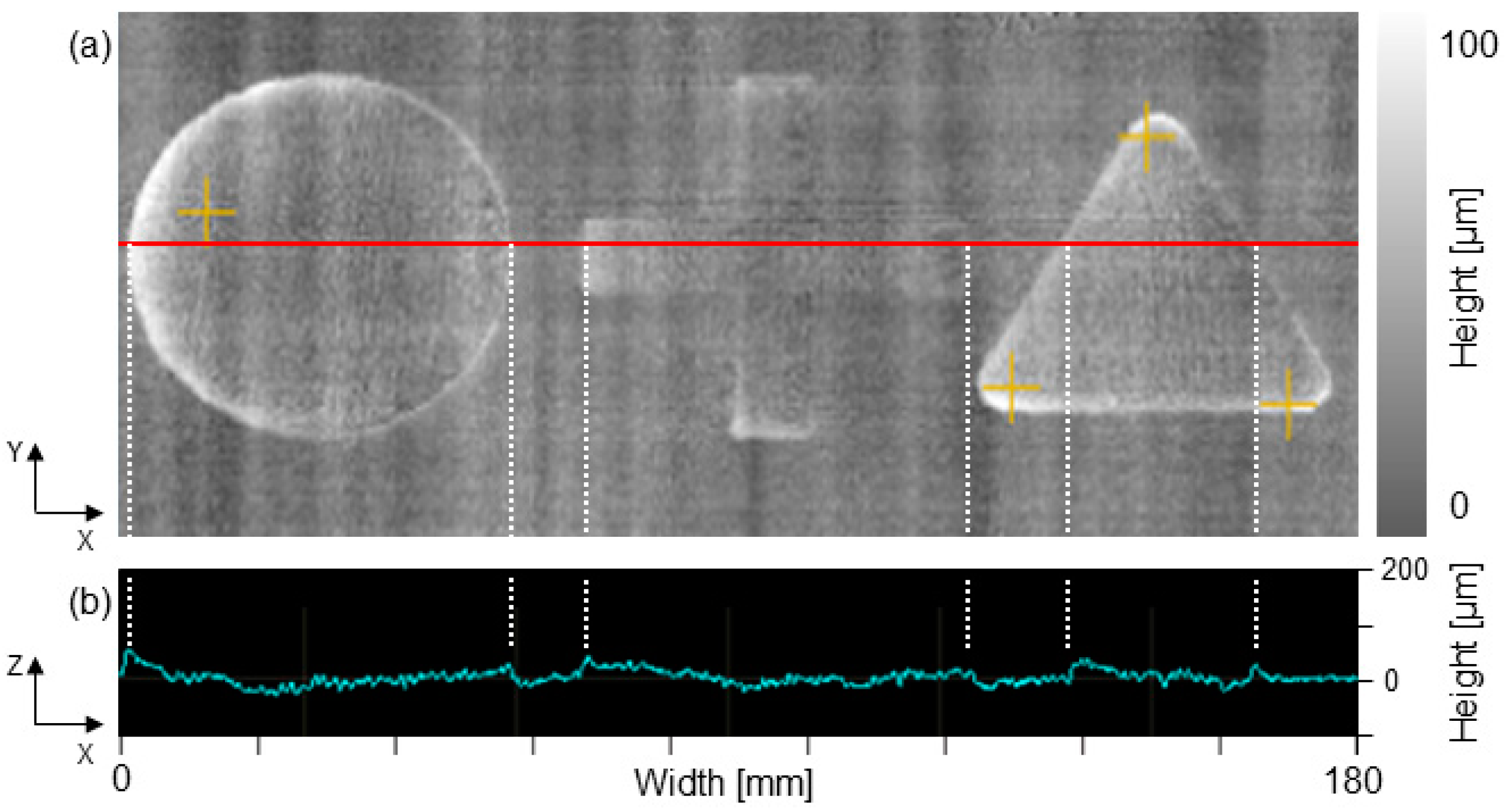
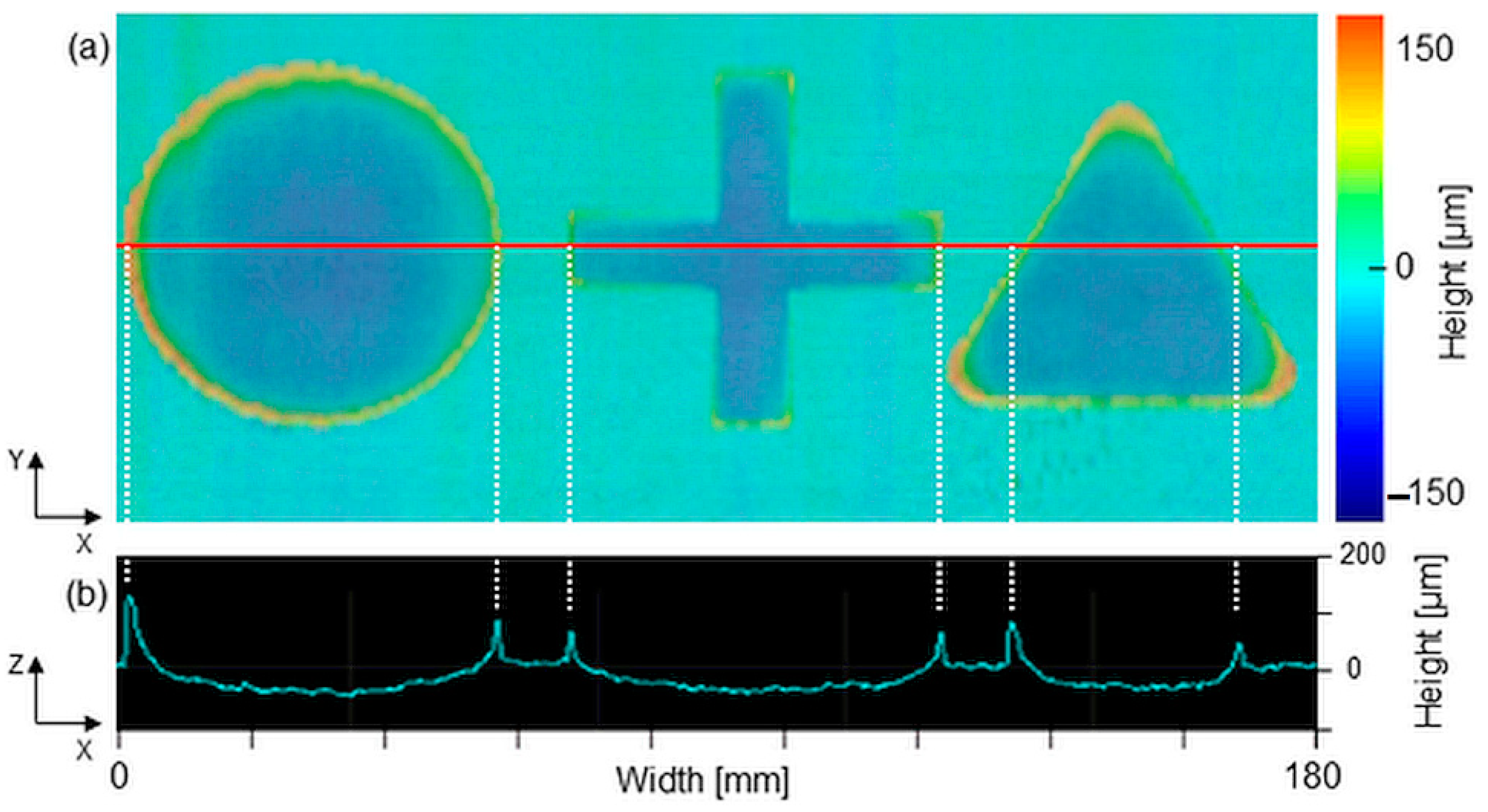
The evaluation of the generated height maps revealed the quantifiable characteristics of curling at the stages of pre- and post-coating. The analysis of the profile section at the post-coating stage in Figure 15a revealed slight deformation and thus an increase of height values close to the free edges of all build parts. Considering the course of height alongside the x-axis (b), peaks are visible and measurable at transition points from curled parts to the powder bed surface. For the variations in height, the maximum value of 80 μm was detected at the left outside edge of the circular part.
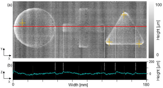
Figure 15.
Height map at the post-coating stage (a) of a segment area of the powder bed surface. The corresponding profile section in (b) represents the deformation and thus height variation at the defined position on the y-axis. The visible peaks in the profile section (b) are tagged to the related segments at the topological map (a).
While the analysis of the profile sections at the post-coating stage revealed slightly increased height values and subsequent drops at transition points, the pre-coating stage after powder melting provided completely different results regarding the progression of height values along the x-axis. Figure 16 shows the 3D topology (a) after laser exposure, which contains segment areas of merged powder resulting in negative values with respect to the powder bed surface, as well as curled peripheral zones at the free edges of all build parts. By analyzing the height values alongside the x-axis (b), a clear development of curling is demonstrated again, resulting in a curvature progression at the merged segments of the components. However, compared to the profile sections after recoating, strong distortionary peaks in height values are revealed at the transition points from curled parts to the powder bed surface.
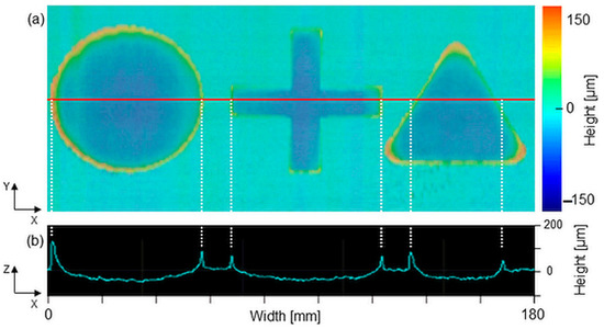
Figure 16.
Height map at the pre-coating stage (a) of a segment area of the powder bed surface after laser exposure. The corresponding profile section (b) reveals strong peaks in height values at the transition points.
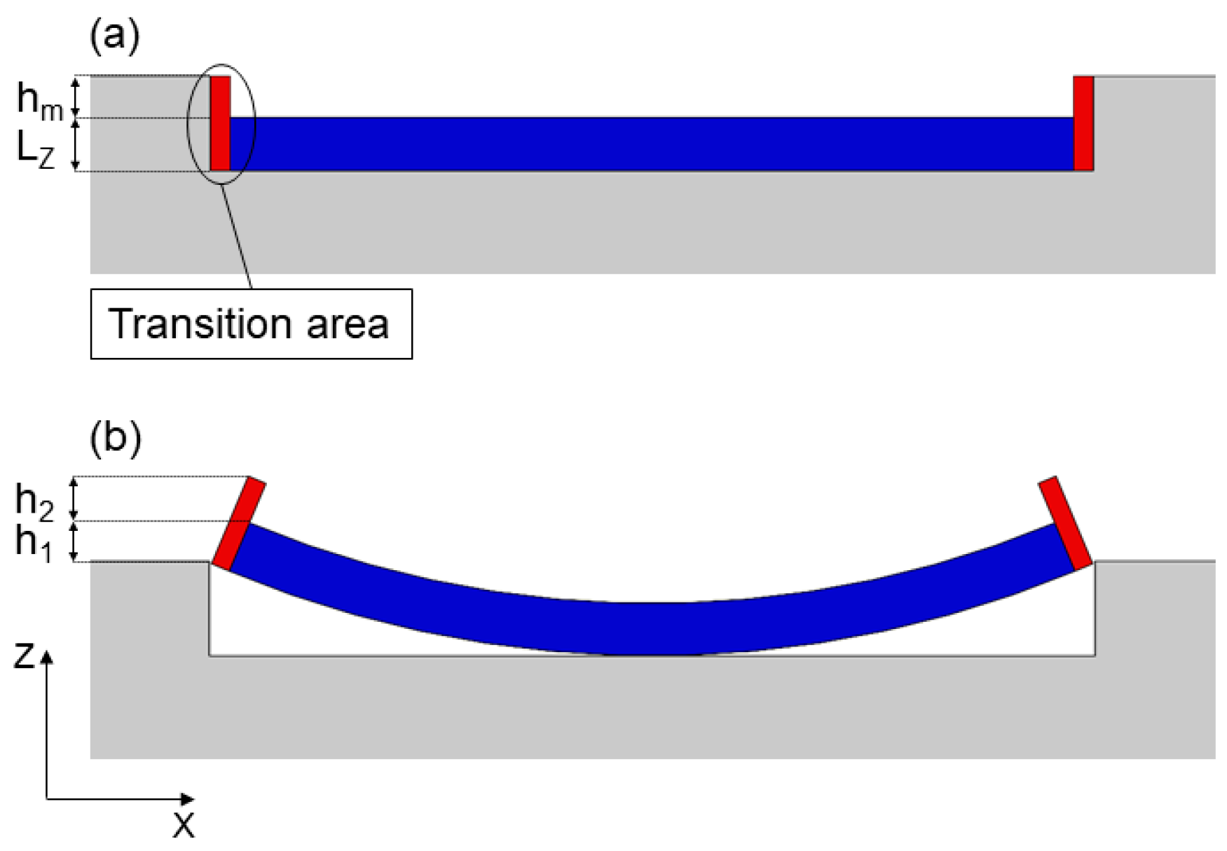
If the overall process of powder bed fusion is considered in detail, a transition area between merged build parts and the surrounding powder is proven according to the results shown in Figure 16. Within this transition area, non-related powder particles are partially molten and stick to the components due to heat conduction. The resulting area is not part of the actual component and forms a rough surface that must be sandblasted after removal from the powder bed.
Another phenomenon called the capillarity effect, proposed by Mattia Mele et al. in [51], could also contribute to the present measurement results in Figure 16. Their study examines the influence of surface tension on contour lines in Multi Jet Fusion. The capillarity effect results from the interaction between the detailing agents and the fusing agents during part building and determines a deviation of the upper planar geometries when close to the edges of the molten material and the powder bed. The uniformity of these phenomena is strongly influenced by the geometry of the layer. Although Multi Jet Fusion is a different manufacturing process, it could well be that there are similarities in the sub-processes and that this phenomenon amplifies the measurable curling effect in laser sintering as shown in Figure 16. The derivation of the respective peaks and their impact on the effective curling height (ECH) at non-coated process states is depicted in Figure 17.
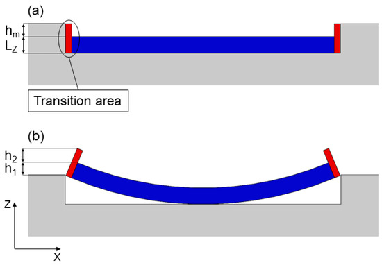
Figure 17.
The cross section of the build part in the xz-plane after laser exposure. The transition area occurs between the actual part and the surrounding powder bed. (a) shows the process state without lifting of free edges with LZ as current layers and hm as melting depth. (b) shows the current process state with curling and thus a resulting calculation of height peaks.
With reference to Figure 17, the ECH peak can be calculated by summing the actual height h1 of the part lifting from the powder bed surface and the additional height h2 of the adhering partially molten powder particles and material affected by the capillarity effect at the transition area. The results of the profile measurements clearly indicate the height variations shown on the 3D surface maps and confirm the related temperature distribution. Slicing the surface profile at a defined position on the y-axis enables the allocation of quantifiable values to curled sections on the powder bed surface. On comparing the progression of the height values shown on the profile measurements, a clear deviation at different process conditions can be seen.
4. Discussion
This paper proposes an approach of real-time process monitoring and in situ defect detection in PBF-LB/P by the simultaneous application of industrial grade laser profilometry and thermal imaging. As the main part of this study, the 3D mapping of the entire powder bed surface inside the installation space and the representation of the related temperature fields were successfully realized for the first time.
Correlations of thermal distributions and the influences on metrics such as powder layer quality, curling height, and associated melting depth were revealed by gathering data on structural height maps. The resulting data provided by the two different sensor concepts was considered individually to derive independent results as well as simultaneously synchronized to confirm correlations. The modified settings on the thermal color map and the depicted temperature range enabled the verifiable visualization of artificially created curling failures in the powder bed of an EOS Formiga P 110 laser sinter system. The adaption of the process by lowering the temperature to 97% and iteratively extending the layer cooling time, which is usually related to the internal exposure strategy, enabled the simulation of curling within different degrees of intensity and at several process stages such as post-coating and pre-coating after laser exposure. The visibility of curling failure and related temperature fields at coated and non-coated areas of the build parts demonstrated that the thermal conductivity changes within phase transition of powder to solid. In order to confirm the height differences indicated by the thermal recordings due to lifting of parts from the powder bed, the radiometric output data of the laser profilometer were analyzed at equal time steps of process progression. The linear translation of the laser profilometer generated 3D height maps, highlighting structural failures by measuring the complete powder bed surface inside the installation space. Considering both sets of data, an exact match of curling locations on the thermal images and on the 3D topology maps was confirmed, which further establishes the verifiable detection of curling failures by thermal imaging.
The analysis of the profile sections on the xz-plane revealed the exact progression of curling height in relation to the powder bed surface as a reference plane, including peak values as transition points from curled parts to the powder bed surface, starting at 23 µm to a maximum value of 560 µm. The direct comparison of measured curling behavior at pre- and post-coating states indicated the development of a transition area at peripheral zones of build parts, resulting in partly melted powder sticking to the components, leading to additional peaks on top of the of the components. The effective curling height (ECH) after laser exposure was verified as the sum of the actual height h1 of part lifting and the additional height h2 of adherent partly molten powder particles and material affected by the capillarity effect as described in [51]. Further effects were observed, such as measured warpage of the part center in the negative z direction, induced by the creation of tensile stresses on the top and compressive stresses on the bottom of parts, as previously theoretically described by Mercelis and Kruth in [48] and by Sillani in [17]. This work does not consider the effects of powder cake cooling and crystallization kinetics on further distortion effects and mechanical properties of the finished parts. In [52], Hooreweder et al. discuss the influence of the building direction of sintered parts on fatigue properties, the density, the degree of crystallinity, and the crystal structure. Another example is given in [53] by Dupin et al. where the influence of the microstructure and crystalline features on the mechanical properties of sintered parts is reviewed. The study by Craft et al. [54] highlights the microstructural characteristics of different cooling rates in additive manufacturing processes.
5. Conclusions
This study demonstrated the successful implementation of process monitoring in the powder bed fusion of polymers, while still exhibiting limitations by restricted real-time intrusion into process parameters. This approach is capable of providing real-time data that could effectively be deployed in a machine setting to automatically adjust temperatures of the heating system if a threshold of measured curling is reached. It should be noted that the results are only valid for the approach presented, as the calibration status of individual machines and sensor types can vary greatly. The results can also be used for future profound investigations of sub-processes regarding crystallization behavior, the influence of hatching strategies, and cooling rates of the powder cake.
Compared to methods of process monitoring by deep learning, this study proposes an effective way of defect detection, requiring less data and lower computational overheads. It would be purposeful to further investigate the use of deep learning to process the data to include physical influences, online parameter optimization, and other sensor technologies to provide additional data.
Author Contributions
Conceptualization, V.K. and L.S.; Data curation, V.K. and L.S.; Formal analysis, V.K. and L.S.; Funding acquisition, V.K., M.B. and A.O.; Investigation, V.K. and L.S.; Methodology, V.K. and L.S.; Project administration, V.K.; Resources, V.K. and L.S.; Software, V.K. and L.S.; Supervision, V.K., M.B. and A.O.; Validation, V.K. and L.S.; Visualization, V.K.; Writing—original draft, V.K.; Writing—review & editing, V.K., M.B. and A.O. All authors have read and agreed to the published version of the manuscript.
Funding
The research leading to these results was funded under the cooperative doctoral program “Digiphot” between FH Campus Wien and TU Wien. This work was also supported by the City of Vienna: MA23—Projekt 29-22, “Artificial Intelligence” and MA23—Projekt 30-25, “AI & VR Lab”.
Institutional Review Board Statement
Not applicable.
Informed Consent Statement
Not applicable.
Data Availability Statement
Not applicable.
Acknowledgments
A big thank you goes to David Nechi, who made this project possible with his expertise in handling and operating the laser sintering system.
Conflicts of Interest
The authors declare no conflict of interest. The funders had no role in the design of the study; in the collection, analyses, or interpretation of data; in the writing of the manuscript; or in the decision to publish the results.
References
- Eyers, D.R.; Potter, A.T. Industrial Additive Manufacturing: A manufacturing systems perspective. Comput. Ind. 2017, 92–93, 208–218. [Google Scholar] [CrossRef]
- Vafadar, A.; Guzzomi, F.; Rassau, A.; Hayward, K. Advances in Metal Additive Manufacturing: A Review of Common Processes, Industrial Applications, and Current Challenges. Appl. Sci. 2021, 11, 1213. [Google Scholar] [CrossRef]
- Ngo, T.D.; Kashani, A.; Imbalzano, G.; Nguyen, K.T.Q.; Hui, D. Additive Manufacturing (3D Printing): A Review of Materials, Methods, Applications and Challenges. Compos. Part B Eng. 2018, 143, 172–196. [Google Scholar] [CrossRef]
- Srivastava, M.; Rathee, S. Additive manufacturing: Recent trends, applications and future outlooks. Prog. Addit. Manuf. 2021, 7, 261–287. [Google Scholar] [CrossRef]
- Liu, Z.; Zhao, D.; Wang, P.; Yan, M.; Yang, C.; Chen, Z.; Lu, J.; Lu, Z. Additive manufacturing of metals: Microstructure evolution and multistage control. J. Mater. Sci. Technol. 2022, 100, 224–236. [Google Scholar] [CrossRef]
- Zhang, D.; Lim, W.Y.S.; Duran, S.S.F.; Loh, X.J.; Suwardi, A. Additive Manufacturing of Thermoelectrics: Emerging Trends and Outlook. ACS Energy Lett. 2022, 7, 720–735. [Google Scholar] [CrossRef]
- Kusoglu, I.M.; Doñate-Buendía, C.; Barcikowski, S.; Gökce, B. Laser Powder Bed Fusion of Polymers: Quantitative Research Direction Indices. Materials 2021, 14, 1169. [Google Scholar] [CrossRef]
- Hejmady, P.; van Breemen, L.C.; Hermida-Merino, D.; Anderson, P.D.; Cardinaels, R. Laser sintering of PA12 particles studied by in-situ optical, thermal and X-ray characterization. Addit. Manuf. 2022, 52, 102624. [Google Scholar] [CrossRef]
- Colorado, H.A.; Mendoza, D.E.; Lin, H.-T.; Gutierrez-Velasquez, E. Additive manufacturing against the Covid-19 pandemic: A technological model for the adaptability and networking. J. Mater. Res. Technol. 2022, 16, 1150–1164. [Google Scholar] [CrossRef] [PubMed]
- Bakshi, K. A Review on Selective Laser Sintering: A Rapid Prototyping Technology. IOSR J. Mech. Civ. Eng. 2016, 4, 53–57. [Google Scholar] [CrossRef]
- Zhang, Y.; Jarosinski, W.; Jung, Y.-G.; Zhang, J. 2-Additive manufacturing processes and equipment. In Additive Manufacturing; Zhang, J., Jung, Y.-G., Eds.; Elsevier Science & Technology: Saint Louis, MO, USA, 2018; pp. 39–51. [Google Scholar] [CrossRef]
- Reiff, C.; Wulle, F.; Riedel, O.; Onuseit, V.; Epple, S. On Inline Process Control for Selective Laser Sintering. In Proceedings of the 8th International Conference on Mass Customization and Personalization, Novi Sad, Serbia, 19–21 September 2018. [Google Scholar]
- Schmachtenberg, E.; Seul, T. Model of isothermic laser-sintering. In Proceedings of the 60th Annual Technical Conference of the Society of Plastic Engineers (ANTEC), San Francisco, CA, USA, 5–9 May 2002. [Google Scholar]
- Drummer, D.; Greiner, S.; Zhao, M.; Wudy, K. A novel approach for understanding laser sintering of polymers. Addit. Manuf. 2019, 27, 379–388. [Google Scholar] [CrossRef]
- Wegner, A. Theorie über die Fortführung von Aufschmelzvorgängen als Grundvoraussetzung für eine Robuste Pro-Zessführung beim Laser-Sintern von Thermoplasten. Master’s Thesis, Fakultät für Ingenieurwissenschaften, Abteilung Maschinenbau und Verfahrenstechnik, Universität Duisburg-Essen, Essen, Germany, 2015. [Google Scholar]
- Wegner, A.; Witt, G. Understanding the decisive thermal processes in laser sintering of polyamide 12. AIP Conf. Proc. 2015, 1664, 160004. [Google Scholar] [CrossRef]
- Sillani, F.; MacDonald, E.; Villela, J.; Schmid, M.; Wegener, K. In-situ monitoring of powder bed fusion of polymers using laser profilometry. Addit. Manuf. 2022, 59, 103074. [Google Scholar] [CrossRef]
- Westphal, E.; Seitz, H. A machine learning method for defect detection and visualization in selective laser sintering based on convolutional neural networks. Addit. Manuf. 2021, 41, 101965. [Google Scholar] [CrossRef]
- Almabrouk, M.A. Experimental investigations of curling phenomenon in selective laser sintering process. Rapid Prototyp. J. 2016, 22, 405–415. [Google Scholar] [CrossRef]
- Soe, S.P. Quantitative analysis on SLS part curling using EOS P700 machine. J. Mater. Process. Technol. 2012, 212, 2433–2442. [Google Scholar] [CrossRef]
- Chen, Y.; Peng, X.; Kong, L.; Dong, G.; Remani, A.; Leach, R. Defect inspection technologies for additive manufacturing. Int. J. Extrem. Manuf. 2021, 3, 22002. [Google Scholar] [CrossRef]
- Zhang, B.; Li, Y.; Bai, Q. Defect Formation Mechanisms in Selective Laser Melting: A Review. Chin. J. Mech. Eng. 2017, 30, 515–527. [Google Scholar] [CrossRef]
- Greiner, S.; Wudy, K.; Wörz, A.; Drummer, D. Thermographic investigation of laser-induced temperature fields in selective laser beam melting of polymers. Opt. Laser Technol. 2019, 109, 569–576. [Google Scholar] [CrossRef]
- Greiner, S.; Drummer, D. Infrared monitoring of modified hatching strategies for laser sintering of polymers. Procedia CIRP 2020, 94, 89–94. [Google Scholar] [CrossRef]
- Hofman, J.; Wudy, K. In situ process monitoring in laser-based powder bed fusion of polyamide 12 using thermal imaging. Int. J. Adv. Manuf. Technol. 2022, 122, 4127–4138. [Google Scholar] [CrossRef]
- Phillips, T.; Fish, S.; Beaman, J. Development of an automated laser control system for improving temperature uniformity and controlling component strength in selective laser sintering. Addit. Manuf. 2018, 24, 316–322. [Google Scholar] [CrossRef]
- Zhang, L.; Phillips, T.; Mok, A.; Moser, D.; Beaman, J. Automatic Laser Control System for Selective Laser Sintering. IEEE Trans. Ind. Inform. 2019, 15, 2177–2185. [Google Scholar] [CrossRef]
- Wroe, W.W.; Gladstone, J.N.; Phillips, T.; Fish, S.; Beaman, J.J.; McElroy, A.B. In-Situ Thermal Image Correlation with Mechanical Properties of Nylon-12 in SLS. Rapid Prototyp. J. 2016, 22, 794–800. [Google Scholar] [CrossRef]
- Wegner, A.; Witt, G. Process monitoring in laser sintering using thermal imaging. In Proceedings of the 2011 International Solid Freeform Fabrication Symposium, Austin, TX, USA, 8–10 August 2011. [Google Scholar]
- Borish, M.; Post, B.K.; Roschli, A.; Chesser, P.C.; Love, L.J. Real-Time Defect Correction in Large-Scale Polymer Additive Manufacturing via Thermal Imaging and Laser Profilometer. Procedia Manuf. 2020, 48, 625–633. [Google Scholar] [CrossRef]
- Southon, N.; Stavroulakis, P.; Goodridge, R.; Leach, R. In-process measurement and monitoring of a polymer laser sintering powder bed with fringe projection. Mater. Des. 2018, 157, 227–234. [Google Scholar] [CrossRef]
- Gardner, M.R.; Lewis, A.; Park, J.; McElroy, A.B.; Estrada, A.D.; Fish, S.; Beaman, J.J., Jr.; Milner, T.E. In situ process monitoring in selective laser sintering using optical coherence tomography. Opt. Eng. 2018, 57, 41407. [Google Scholar] [CrossRef] [PubMed]
- Guan, G.; Hirsch, M.; Syam, W.P.; Leach, R.K.; Huang, Z.; Clare, A.T. Loose powder detection and surface charac-terization in selective laser sintering via optical coherence tomography. R. Soc. Proc. 2016, 472, 20160201. [Google Scholar] [CrossRef]
- Phuc, L.T.; Seita, M. A high-resolution and large field-of-view scanner for in-line characterization of powder bed defects during additive manufacturing. Mater. Des. 2019, 164, 107562. [Google Scholar] [CrossRef]
- Sassaman, D.M.; Ide, M.S.; Kovar, D.; Beaman, J.J. Design of an In-situ microscope for selective laser sintering. Addit. Manuf. Lett. 2022, 2, 100033. [Google Scholar] [CrossRef]
- Fish, S.; Booth, J.C.; Kubiak, S.T.; Wroe, W.W.; Bryant, A.D.; Moser, D.R.; Beaman, J.J. Design and subsystem development of a high temperature selective laser sintering machine for enhanced process monitoring and control. Addit. Manuf. 2015, 5, 60–67. [Google Scholar] [CrossRef]
- Alzubaidi, L.; Zhang, J.; Humaidi, A.J.; Al-Dujaili, A.; Duan, Y.; Al-Shamma, O.; Santamaría, J.; Fadhel, M.A.; Al-Amidie, M.; Farhan, L. Review of deep learning: Concepts, CNN architectures, challenges, applications, future directions. J. Big Data 2021, 8, 1–74. [Google Scholar] [CrossRef] [PubMed]
- Klamert, V.; Schmid-Kietreiber, M.; Bublin, M. A deep learning approach for real time process monitoring and curling defect detection in Selective Laser Sintering by infrared thermography and convolutional neural networks. Procedia CIRP 2022, 111, 317–320. [Google Scholar] [CrossRef]
- Xiao, L.; Lu, M.; Huang, H. Detection of powder bed defects in selective laser sintering using convolutional neural network. Int. J. Adv. Manuf. Technol. 2020, 107, 2485–2496. [Google Scholar] [CrossRef]
- Bauer, M.; Augenstein, C.; Schäfer, M.; Theile, O. Artificial Intelligence in Laser Powder Bed Fusion Procedures—Neural Networks for Live-Detection and Forecasting of Printing Failures. Procedia CIRP 2022, 107, 1367–1372. [Google Scholar] [CrossRef]
- Kanko, J.A.; Sibley, A.P.; Fraser, J.M. In situ morphology-based defect detection of selective laser melting through inline coherent imaging. J. Mater. Process. Technol. 2016, 231, 488–500. [Google Scholar] [CrossRef]
- Li, Z.; Liu, X.; Wen, S.; He, P.; Zhong, K.; Wei, Q.; Shi, Y.; Liu, S. In Situ 3D Monitoring of Geometric Signatures in the Powder-Bed-Fusion Additive Manufacturing Process via Vision Sensing Methods. Sensors 2018, 18, 1180. [Google Scholar] [CrossRef]
- Maucher, C.; Werkle, K.T.; Möhring, H.-C. In-Situ defect detection and monitoring for laser powder bed fusion using a multi-sensor build platform. Procedia CIRP 2021, 104, 146–151. [Google Scholar] [CrossRef]
- McCann, R.; Obeidi, M.A.; Hughes, C.; McCarthy, E.; Egan, D.S.; Vijayaraghavan, R.K.; Joshi, A.M.; Garzon, V.A.; Dowling, D.P.; McNally, P.J.; et al. In-situ sensing, process monitoring and machine control in Laser Powder Bed Fusion: A review. Addit. Manuf. 2021, 45, 102058. [Google Scholar] [CrossRef]
- Zhirnov, I.; Panahi, N.; Åsberg, M.; Krakhmalev, P. Process quality assessment with imaging and acoustic monitoring during Laser Powder Bed Fusion. Procedia CIRP 2022, 111, 363–367. [Google Scholar] [CrossRef]
- Laumer, T.; Stichel, T.; Amend, P.; Schmidt, M. Simultaneous laser beam melting of multimaterial polymer parts. J. Laser Appl. 2015, 27, S29204. [Google Scholar] [CrossRef]
- Keyence. LJ-X8400 Technical Description; Keyence: Osaka, Japan, 2022. [Google Scholar]
- Mercelis, P.; Kruth, J. Residual stresses in selective laser sintering and selective laser melting. Rapid Prototyp. J. 2006, 12, 254–265. [Google Scholar] [CrossRef]
- Incropera, F.P.; DeWitt, D.P. Fundamentals of Heat and Mass Transfer, 4th ed.; Wiley: New York, NY, USA, 1996. [Google Scholar]
- EOS. PA2200 Technical Description; EOS: Krailling, Germany, 2022. [Google Scholar]
- Mele, M.; Campana, G.; Monti, G.L. Modelling of the capillarity effect in Multi Jet Fusion technology. Addit. Manuf. 2019, 30, 100879. [Google Scholar] [CrossRef]
- Van Hooreweder, B.; Moens, D.; Boonen, R.; Kruth, J.-P.; Sas, P. On the difference in material structure and fatigue properties of nylon specimens produced by injection molding and selective laser sintering. Polym. Test. 2013, 32, 972–981. [Google Scholar] [CrossRef]
- Dupin, S.; Lame, O.; Barrès, C.; Charmeau, J.-Y. Microstructural origin of physical and mechanical properties of polyamide 12 processed by laser sintering. Eur. Polym. J. 2012, 48, 1611–1621. [Google Scholar] [CrossRef]
- Craft, G.; Nussbaum, J.; Crane, N.B.; Harmon, J. Impact of extended sintering times on mechanical properties in PA-12 parts produced by powderbed fusion processes. Addit. Manuf. 2018, 22, 800–806. [Google Scholar] [CrossRef]
Disclaimer/Publisher’s Note: The statements, opinions and data contained in all publications are solely those of the individual author(s) and contributor(s) and not of MDPI and/or the editor(s). MDPI and/or the editor(s) disclaim responsibility for any injury to people or property resulting from any ideas, methods, instructions or products referred to in the content. |
© 2023 by the authors. Licensee MDPI, Basel, Switzerland. This article is an open access article distributed under the terms and conditions of the Creative Commons Attribution (CC BY) license (https://creativecommons.org/licenses/by/4.0/).

