Abstract
In this paper, the multiscale analysis of the reproduction accuracy of jaw geometry obtained via the use of selected orthodontic materials is discussed. Impressions were made from two types of impression material. An accuracy assessment of the model geometry mapping was performed using noncontact systems, including a fringe projection optical 3D scanner, computed tomography, and a focus variation microscope. Measurements were made in three modes for comparison, as were the silicone and polyether impression materials. These modes were a jaw model and impression, an impression and plaster model, and plaster and jaw models. The research results are presented as colorful maps of deviations. Data analysis showed that deviations were the smallest in the case of silicone and that the best fit occurred between the silicone impression and the plaster model. The conducted research confirmed the validity of the assumptions considering the use of multiscale analysis for geometric analysis. The use of modern multiscale measurement methods allows for shorter and more efficient prosthetic operations. At present, these devices are expensive and complicated to use, but developments in technology should simplify the process, and prosthetic professionals should be aware of the possibilities described in the paper.
1. Introduction
Currently, implantoprosthetic orthodontics and other fields of dentistry are experiencing rapid progression [1,2,3,4,5]. These implants use dental models created based on a matrix of impressions [6] and are produced when it is necessary to use braces to correct malocclusion, insert implants, crowns, or bridges.
The main task of the impression is to accurately reproduce the shape, size, and position of the teeth in dental arches in order to produce the most accurate model on the corresponding matrix. Consequently, impression materials should fulfil a number of conditions. Requirements for such materials among doctors and dental technicians include environmental inertness, ease of preparation, adequate flow properties, appropriate and short setting time in the mouth, the possibility of adjusting the setting time, easy release of the impression, the accurate reproduction of details, resistance to the negative effects of body fluids, low cost of the materials and instrumentation used, ease of disinfection, compatibility with casting materials, and obtaining plaster models with a smooth surface [7,8,9,10,11]. For the patient, it is important that the impression material has a pleasant taste and is nontoxic, stays in the mouth for a short time, and is quickly and easily removed from the mouth [12].
In order to meet the requirements of patients and to enable the dentist and technician to reliably do their jobs, it is important to implement modern technologies that speed up and streamline prosthetic operations. This measure will allow the finished product to be made without the need for additional processing. Full standardization of operations, however, is hampered by the great diversity of clinical cases. This diversity often requires additional machining of pre-prepared prostheses. The use of modern technology through multiscale digitization will allow the design and manufacture of work in a way that reduces the need for the postprocessing and correction of finished dental prostheses. In this way, the patient’s final visit to the dentist’s office during the denture seating process will be significantly reduced.
A very important issue is the geometric accuracy of the mapped jaw [13,14]. The geometric accuracy of the impression is influenced by a great number of factors: the impression technique, the impression method, the type of impression tray, and the types and properties of the impression compounds [15,16]. Accurate reproduction of the jaw geometry, position, and shape of the teeth are very important to precisely match components produced by technicians who are not in direct contact with the patient or the teeth and other anatomical structures situated in the patient’s mouth. Aesthetics and comfort are very important to the patient [17]. More than a dozen materials are available on the market with different properties, applications, and mapping accuracy.
The most commonly used impression materials are increasingly being replaced by other methods of mapping jaw geometry [18,19]. One of these methods is the use of an oral scanner [20,21,22,23], which allows precise digital models of the dentition to be made without the need to use impression materials [24]. Optical scanners with various digitization techniques included in CAD/CAM systems are also used in dentistry [21]. Most of these systems are used for scanning models in prosthetic laboratories. In recent years, digital imaging techniques have evolved greatly, enabling the development of new systems capable of capturing three-dimensional images of prepared teeth in the patient’s mouth [25,26]. Nevertheless, the most popular and widely used methods in dental practice continue to employ classic impression materials.
The authors in [27] presented 3D scanning methods commonly used in dentistry. The authors also described the advantages of using these methods. The authors in [28] presented a literature review on the application of micro-CT in bioengineering applications. The use of micro-CT for bone analysis was presented in [29,30]. However, an analysis of recent literature did not find a comprehensive research approach for the multiscale evaluation of jaw geometry reproduction using a 3D scanner, micro-CT, or focus variation microscope. Such data fusion is a novel approach that could provide many benefits to dental science.
Accuracy analyses of materials used in dental implants and orthodontics have been performed. Studies on the accuracy of geometry mapping were presented, for example, by the authors in [31,32,33,34,35]. These studies, however, were primarily directed towards macroscale geometry analysis. Microscale measurements were directed at determining the surface roughness parameters of orthodontic arches made of different materials [9].
Length and angle metrology has also been undergoing intensive development for many years. This development is linked to the Industry 4.0 strategy in which angle metrology indirectly fits [36]. One of the key trends in 4.0 metrology is the use of multisensor and multiscale analysis [36,37,38]. The use of different sensors makes it possible to acquire data using different techniques. Each sensor provides a different set of information, and the combination of these data gives full multiscale information [39]. All this information is based on coordinate metrology, which is a technique that involves measuring geometric features. While this technique is commonly associated with largescale measurements considered to be macro, it also applies to smaller scales such as the nano- and microscale, where this method can measure surface irregularities, as well as the intermediate (meso-) scale, where it can measure the transition between irregularities and geometric features. As dimensions become smaller, the boundaries between scales become blurry, and it is important to analyze the object being measured across all scales to obtain a complete picture. Therefore, metrological verification must include measuring geometric features and shapes, as well as surface roughness, to provide a holistic view of the object being measured.
The aim of the research presented in this article was to confirm the desirability of using state-of-the-art measuring CMs operating at different scales to comprehensively evaluate the representation of jaw geometry obtained using selected orthodontic materials. Such a comprehensive approach has not been presented before, which is the novelty of this article. The increasing demands of patients and the expectations of dentists and dental technicians mean that extensive multiscale examinations should become a common procedure in the near future. The use of a multiscale approach to measurement allows the fusion of data describing different areas of information. Macroscale measurements describe the jaw geometry, the shape and position of individual teeth, as well as the position of teeth relative to each other. The micro-CT examination also allows the impression to be measured together with the jaw model and evaluated without physical separation. Due to its resolution, this method also allows the evaluation of details “invisible” to a 3D scanner. On the other hand, the measurement of surface topography with a focus variation microscope allows a very precise evaluation of the surface for all types of elements measured. The complete data include a set of triangle meshes (STLs) that can be interconnected, enabling the microscale data to be position-defined (specific position) using the macroscale data. This approach also allows the impression material to be assessed in relation to “large flat” tooth surfaces and hard-to-reach areas.
2. Materials and Methods
The primary objective of the presented research task was to analyze the representation accuracy of the geometric features of the human jaw obtained with selected orthodontic materials using contactless measurement methods on a macro- and microscale. For this purpose, photogrammetric methods, computed tomography, and noncontact methods for measuring surface topography were used. Other goals were to apply reverse engineering and rapid prototyping technology to obtain a model of the jaws [40]. The final result is a multiscale analysis directly in line with the idea of Industry 4.0.
This type of research can significantly contribute to new advanced diagnostic methods and allow the construction of implants and prostheses of cartilage–skeletal elements to be accelerated and greatly simplified.
The scope of the present research was as follows:
- Measurements of the jaw model geometry (photogrammetric method, micro-CT);
- Preparation of impressions with selected types of orthodontic impression compounds;
- Measurements of the impression geometry obtained using the photogrammetric method;
- Application of reverse engineering to obtain digital models of the examined jaws;
- Application of rapid prototyping technology (3D printing) to obtain models;
- Casting of plaster models of the jaws using dental plaster;
- Measurements of impression geometry obtained using nonmedical computed tomography;
- Measurements of the obtained plaster models and models obtained via 3D printing;
- Surface structure measurements of selected dental impressions and gypsum models.
The dentition geometry obtained via orthodontic impression materials, photogrammetric measurement systems that allow imaging, and evaluation of the entire element surface on a macroscale are very effective at verifying reproduction accuracy [41,42,43,44]. Photogrammetric methods refer to the techniques used for obtaining measurements and information about objects and features from photographs or images. Such techniques are noncontact, nondestructive, and nonintrusive methods of data acquisition that have many applications in various fields. Length metrology involves measuring elements of the characteristic features of an object encoded in the form of markers and points, lines, or stripes projected onto the object. Photogrammetric measurement methods work on the principle of triangulation, so the geometric relationships present in a triangle are used to measure distance [45,46]. Photogrammetric methods make it possible to measure the geometric features of individual elements made of different materials such as the jaw model, the orthodontic impression, and the obtained plaster model of the dentition [47].
It should be emphasized that dental plaster, which reproduces the arrangement of the jaw based on the orthodontic impressions made, is subject to shrinkage and deformation during drying and may be damaged during the separation of the plaster model from the impression [48,49]. In this case, spatial analysis of plaster models of the jaws without separating them from the impression is possible through the use of a CT scanner [50,51]. Tomographic measurements are carried out using X-rays that are attenuated as they pass through the object under examination, creating an X-ray image. Computed tomography has been used in medicine since the 1970s. However, only micro-CT offers resolutions suitable for the analyses presented in this article [52]. It is possible to evaluate the components in an assembly and virtually detach them, which allows assessment of the actual adhesion of the impression materials to the tooth surface. Unfortunately, micro-CT is not adapted to the examination of a living person like a classic CT device, so studies conducted on applied models were necessary. During the examination, a series of images were taken at different angular positions to obtain a spatial image [53]. The study used a micro-CT device, which allows for data with better resolution than that under commonly used medical CT scanners [54]. Based on the volumetric image (after a thoroughly prepared calibration [55]), it becomes possible to analyze both the geometric deformation of surfaces under examination and the reproduction accuracy shape of the dentition by means of a plaster material. For some applications, optical scanners and computed tomographs give very similar results, as demonstrated by comparative analysis [56].
An important aspect of a jaw mapping evaluation with impression materials is measurements describing the surface structure on a microscale [9]. Such measurements provide evidence of mapped surface quality [57], which has a significant impact on the aesthetics of the fabrication of, for example, dental prostheses. Assessment of the surface structure linked to microscale shape analysis is made possible by focal differentiation microscopy. The principle of focus variation microscopy is based on using the sharpness of a surface image in an optical microscope to assess the change in surface roughness. The object to be measured is illuminated with a light with suitable modulation, transmitted through the optics and focused on the surface to be measured. The reflected light is returned through the optics and recorded by a digital detector searching for the focused beam. The image of the surface is shaped by the optical system allowing both photometric (brightness, color, etc.) and geometric (distance and shape) information to be obtained. An integral feature of this method is the existence of a focused image surface (FIS), defined as a surface formed by a cloud of points for which the camera lens allows a focused light beam to be obtained. According to the principles and theory of geometrical optics, there is a direct relationship between the shape of the real object and the shape of its image focus surface, making it possible to derive the shape of the object surface (or its irregularities) from the shape of the FIS [57].
Figure 1 shows a general block diagram of the measurement path incorporating the three noncontact measurement methods that form the basis of the multiscale analysis presented in this article. Based on measurements, the data obtained in the form of a point cloud were further processed and optimized. The point clouds corresponding to the measurement data were subjected to a polygonization process. This process involves building a model in the form of a triangle mesh with vertices located at each point in the set, thereby generating files in the STL format and creating 3D models of the measured objects. Digitalization of each object using an optical scanner produced multiple individual scans that had to be automatically combined using an intelligent algorithm based on surface matching and a combination of reference points to obtain the most complete model possible. For the measured impression data obtained to be compared with the jaw model and the plaster models, they had to undergo an inversion operation, i.e., a symmetrical outward extension along the vertical axis. This ensured that all measurements were for convex objects.
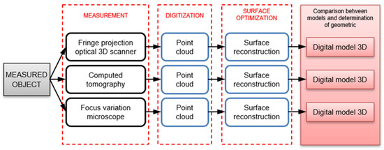
Figure 1.
General block diagram of the measurement path including the three contactless measurement methods that form the basis of the multiscale analysis.
Two software programs were used to analyze the obtained measurement data. The macroscale analysis was carried out using the GOM Inspect Professional (GOM GmbH, Braunschweig, Germany) program, while the microscale analysis was carried out using the MountainsMap (Digital Surf® Headquarters, Besançon, France) software. The results of the comparisons are presented in the form of a color map, where deviations in inspection points are represented by a scale. A diagram of the measurements and analyses carried out is shown in Figure 2. As can be seen, the entire research task was divided into a series of analyses, from which four main stages of work were identified. The following paper presents a synthesis and selected examples of the completed research.
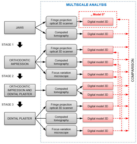
Figure 2.
Flow chart of the measurements and analyses carried out.
3. Results and Discussion
The research presented in this paper was based on a dental model of the upper part of the human jaw (Figure 3). Prior to use, the model was measured using an GOM ATOS Core 185 (GOM GmbH, Braunschweig, Germany) photogrammetric measurement system, which was adopted as the base model in the further comparative analyses “Model 0”. Additionally, the base model was digitized using a GE Phoenix v|tome|x s240 (Waygate Technologies, Wunstorf, German) micro-CT device to complete the measurement information with surfaces inaccessible to scanning with structured light.
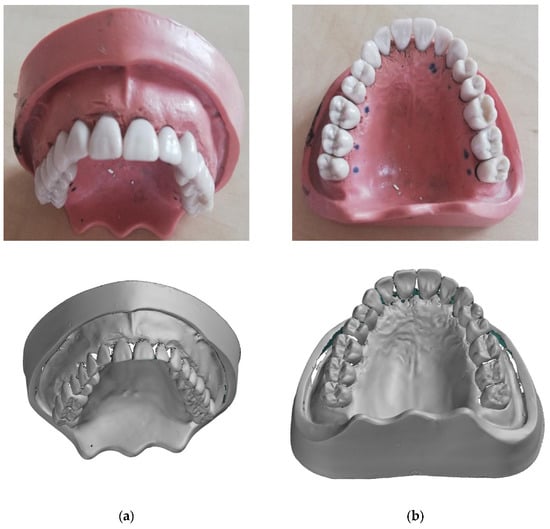
Figure 3.
Dental model of the lower part of human jaw: (a) Actual view; (b) Digital “model 0”.
The next step was to prepare impressions on the human jaw model. The following impression compounds were used in the study: silicone—Express XT Penta Putty (3M Oral Care, St. Paul, MN, USA) and Polyether Impregum Penta (3M Oral Care, St. Paul, MN, USA) (Figure 4). A geometric evaluation of the models obtained using different dental materials was presented by the authors in [31,32,33,34,35]. The present study focuses on a multiscale analysis of the objects considered.
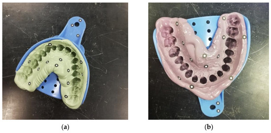
Figure 4.
Dental impressions from silicone material (a) and polyether material (b).
The finished impressions were measured using a photogrammetric measuring system and micro-CT. Plaster models were then cast using Stodent Class II dental plaster (Zhermack S.p.A., Badia Polesine, Italy) (Figure 5). Once the plaster had set, the models were measured using micro-CT before being removed from the impression to identify defects resulting from the separation of the impression compound and the plaster model. The plaster models, after removal from the impressions, were finally measured using an optical scanner and micro-CT.
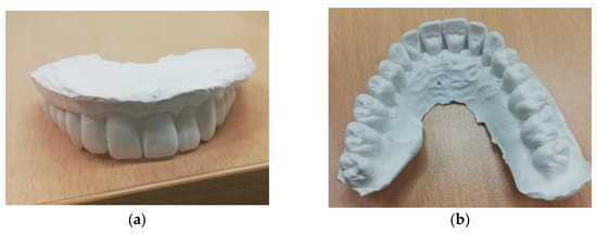
Figure 5.
Example of a plaster model of a jaw: (a) Front view; (b) Top view.
As part of the research carried out, we attempted to replace plaster materials with models produced using 3D printing (Figure 6) [40]. The use of rapid prototyping technology allows models to be made based on a jaw’s digitized model, which avoids defects associated with the drying process of a model made from dental plaster and from damage caused in the process of separating the plaster model from the impression. The models created during the 3D printing process were made using a ZORTRAX M200 Plus (Zortrax S.A. Olsztyn, Poland) printer.
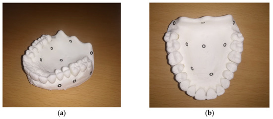
Figure 6.
Example of a jaw model made using a 3D printer: (a) Side view; (b) Top view.
As already mentioned, the scanning on the 3D optical scanner resulted in raw data in the form of a point cloud. This model was transformed into a triangular network after polygonization. Some areas of the model were difficult to digitize, such as the interdental spaces and the border between the teeth and the gum. The source of these difficulties lies in the complex geometry of elements, which consists of freeform surfaces arranged in such a way that they become an obstacle for measurements using the optical method. The inability to measure these zones resulted in some gaps in the model. Some of these gaps were closed with special algorithms to estimate the area based on the neighboring rows of triangles around the gap. In other words, in areas where it was not possible to record measured points, the area was calculated mathematically. Not all gaps could be closed, as further modifications to the model would lead to a loss of accuracy. In the case of the model obtained using the CT scanner, a full representation of the jaw model was achieved. Nevertheless, the model from the 3D scanner was adopted as a reference due to its overall higher accuracy. Figure 7 shows a comparison of the two models, with one obtained from the 3D scanner and the other from the micro-CT.
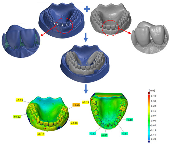
Figure 7.
Comparison of jaw models digitized on an optical 3D scanner and micro-CT.
Figure 7 shows that the deviations between the 3D scanner and micro-CT ranged from −0.12 mm to 0.26 mm. This result demonstrates the scale of possible misunderstanding related to component deformation at the beginning of the analysis and the importance of accurately defining the reference element.
As previously mentioned, different orthodontic impressions were made based on a real jaw model. Both were digitized using different measurement methods: a 3D scanner and CT scanner. Each digitized piece was compared with the “0 model”. A color deviation map is shown in Figure 8 for the silicone material and in Figure 9 for the polyether material.
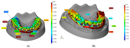
Figure 8.
Comparison of scans of the silicone impression obtained on an optical 3D scanner (a) and micro-CT (b).
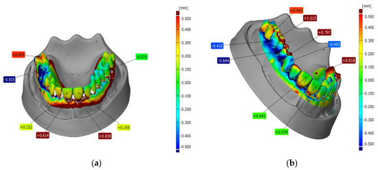
Figure 9.
Comparison of scans of a polyether pulp impression obtained using an optical 3D scanner (a) and micro-CT (b).
In the presented examples, a significant deviation value of more than 1 mm was observed in the maximum case. When comparing deviations between the dental impression model obtained from the 3D scanner and that obtained from the micro-CT, a similar trend was observed, but the deviation values differed in the examined areas by a few tenths of a millimeter. At this stage of analysis, it should be noted that the orthodontic impression materials were characterized by a certain susceptibility to deformation under external influences, which could be observed by introducing dental plaster materials into the impression.
The next step in the analysis was to measure the plaster model before removal from the impression. The combined elements were digitized using a micro-CT scanner, as shown in Figure 10. The constructed cross-section in the area of the anterior teeth shows how the boundary between the two elements was formed based on the density of the material. The model created from the separation of the digital impression and the plaster did not feature the defects and damage that can occur during separation.
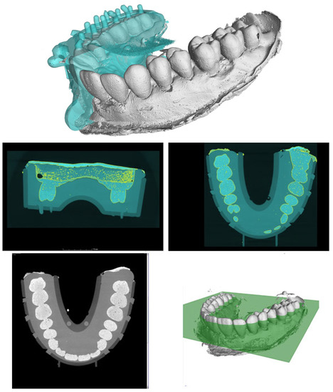
Figure 10.
Combined orthodontic impression (blue) and dental plaster (grey) digitized using micro-CT.
Once the plaster models were separated from the impression materials, they were digitized using a 3D scanner and micro-CT. The results were analyzed in the same way as the impressions. Color deviation maps to visualize the deformation of the models in relation to the “0 model” are shown in Figure 11 and Figure 12. The results presented show a reasonably uniform match between the plaster model based on the silicone impression matrix and the jaw model on both sides. The third incisal tooth presented a deviation value of −0.17 mm, the highest in the entire dental arch. Here, the poorer fit of the models created via micro-CT is clearly noticeable. Large deviations were noted for the right side of the jaw. Teeth 4, 5, and 6 showed deviations of approximately 0.5 to 1.0 mm at the top. On the other hand, at the base, the deviations ranged from approximately −0.5 mm to 0.8 mm.
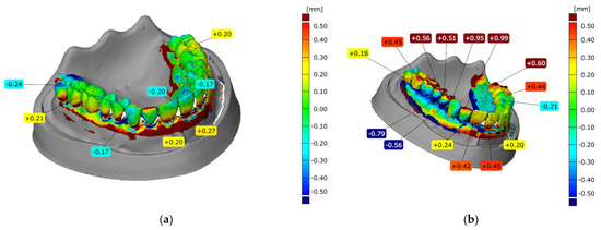
Figure 11.
Comparison of scans of a plaster model created from a silicone impression obtained on an optical 3D scanner (a) and micro-CT (b).
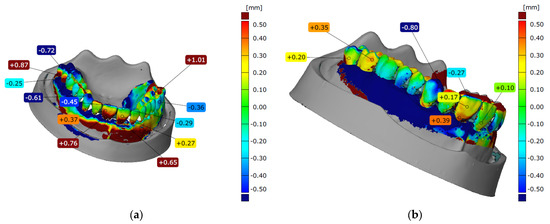
Figure 12.
Comparison of scans of a plaster model created from a polyether material impression obtained on an optical 3D scanner (a) and micro-CT scanner (b).
Based on a comparison, the geometry of the plaster model cast from the polyether impression with the jaw model did not match very accurately. Here, we can see a worse fit on the right compared to the left, as well as on the chewing surfaces in relation to the buccal surfaces and on the molars. Analyzing the obtained color deviation maps, a better fit was observed for the silicone material than the polyether material. In most combinations, the largest deviations were on the last molars.
The fit of the gum mapping was not analyzed, as this fit was affected by the irregular filling of the impression with gypsum material. This phenomenon can be clearly seen when analyzing the plaster models created from the polyether impression (Figure 12). Both the 3D scanner and micro-CT scans showed the greatest deviations for the gingival areas.
An important aspect in evaluating the mapping of jaws with impression materials is measurements describing the surface structure on a microscale. Such measurements indicate the quality of the mapped surfaces, which has a significant impact on the fabrication aesthetics of, for example, dental prostheses. The evaluation of the surface structure at the microscale was carried out using an Alicona InfiniteFocus G5 (Alicona Imaging GmbH, Graz, Austria) differential focusing microscope, which is very useful in dental applications [58]. Due to the small measurement range of the device, measurements were limited only to an analysis of molar surfaces, which can be considered representative of the entire impression when analyzed on a microscale. Since the material of the test object is susceptible to damage and scratching, measurements were carried out using a noncontact system.
Analysis of the surface topography was carried out using the MountainsMap (Digital Surf Headquarters, Besançon, France) software. The impression materials and resulting plaster models were analyzed on a microscale. Example results for the silicone material and the corresponding gypsum model are shown in Figure 13, while results for the polyether material are shown in Figure 14. The parameters describing the surface structures of the example considered are shown in Table 1 and Table 2.
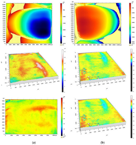
Figure 13.
Graphical representation of the surface texture for the silicone impression (a) and plaster model (b).
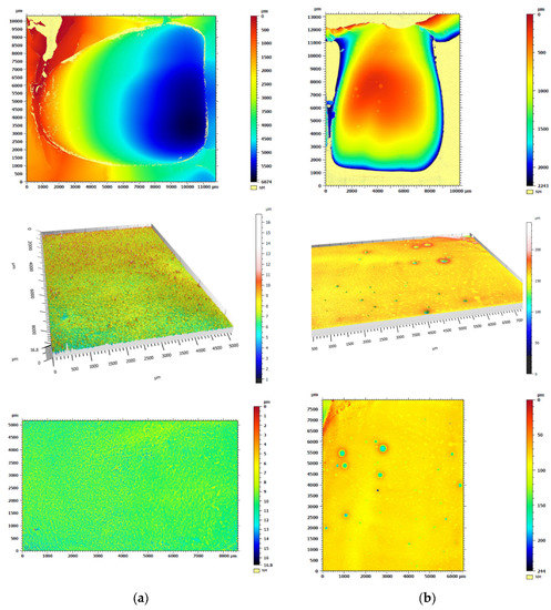
Figure 14.
Graphical representation of the surface texture for the polyether material impression (a) and plaster model (b).

Table 1.
Summary of the basic surface structure parameters for the silicone impression and plaster model.
Table 2.
Summary of basic surface structure parameters for the polyether material impression and plaster model.
Comparing the results for the impression materials and gypsum models, differences in the height parameters describing the surface structure can be clearly observed. These differences are particularly evident for the polyether material and the corresponding gypsum model. The reason for this result may be that air bubbles formed on the surface of the model during the cooling process of the gypsum material.
The final task of this study was an attempt to replace the gypsum materials with models made using 3D printing. In order to determine the accuracy of the reproduction, the obtained model of the jaw was measured using a 3D scanner. Figure 15 shows a comparison between the digitized model made using the incremental method and the model taken as nominal in the form of a color deviation map.
Figure 15.
Comparison of the digitized jaw model made using the incremental method with the model taken as nominal.
The model resulting from 3D printing clearly offers a very good reproduction compared to the nominal model, with deviations from the nominal model not exceeding 0.2 mm. The results of this model obtained by reverse engineering and rapid prototyping indicate the possibility of using an alternative replacement for plaster models obtained with commonly used dental impressions.
4. Conclusions
Due to the wide variety of clinical cases, it is not possible to standardize all activities performed in prosthetics practice. Complicated medical cases with complex geometries and relationships between individual teeth require an unconventional approach to prosthetic design. By using a multiscale assessment, it is possible to better reproduce the patient’s jaw geometry to ensure a tight and durable patient–prosthesis connection.
The analysis of the results indicates that a better fit was obtained with the silicone material than with the polyether material. In most comparisons, the largest deviations were observed on the last molar teeth. Several comparisons also demonstrated abnormalities on the left second incisal tooth. For the polyether material, a clear difference in accuracy between the left and right sides could be observed. The largest deviations were observed on the left premolars and first molar. These deviations may be due to the uneven pressing of the material on this side and the inaccurate molding of the teeth. A color-coded deviation map was created by combining the silicone impression, and the plaster model cast showed the best reproduction of geometry. A comparison of the absolute values of deviations for all right and left first incisal teeth in the central part of the labial surface with the absolute values of the deviations of all right and left second premolar teeth on the buccal cusp yielded similar results. It can be observed that at the front of the jaw on the incisors, these deviations were smaller than those at the back on the premolar teeth.
An attempt to use reverse engineering and rapid prototyping technology to obtain a model of the jaws produced satisfactory results. In the future, this method may provide an alternative to commonly used dental materials.
A limitation of this method is the need for specialized equipment, which is not available in prosthetic surgeries. Consequently, qualified personnel are required to digitize and analyze the acquired data. This solution will not be used universally but only for complex and unusual clinical cases. At present, the solution is also dedicated to patients who are prepared to pay a higher cost for a prosthesis, while at the same time being guaranteed a faster prosthesis without the need for longer fitting times through postprocessing, thus representing a higher level of personalization.
In summary, the comprehensive analysis and research carried out using various tools enabled multiscale analysis that directly fits into the ideas of Industry 4.0.
Author Contributions
Conceptualization, M.J. and L.M.-P.; methodology, M.J., L.M.-P., B.G. and M.M.; validation, M.J., L.M.-P. and B.G.; formal analysis, M.W.; investigation, M.J., L.M.-P., B.G. and M.M.; resources, M.J. and P.M.; writing—original draft preparation, M.J.; writing—review and editing, M.J., L.M.-P., B.G. and M.W.; visualization, M.J. and L.M.-P.; supervision, M.W.; project administration, M.J.; funding acquisition, M.J. All authors have read and agreed to the published version of the manuscript.
Funding
This research was funded by the Ministry of Education and Science in Poland, grant number 02/22/SBAD/1503 and 0614/SBAD/1565.
Institutional Review Board Statement
Not applicable.
Informed Consent Statement
Not applicable.
Data Availability Statement
The data presented in this study are available on request from the corresponding author.
Acknowledgments
The authors would also like to acknowledge Martyna Wiczynska and Patrycja Szefer for fabricating the samples.
Conflicts of Interest
The funders had no role in the design of the study; in the collection, analyses, or interpretation of data; in the writing of the manuscript; or in the decision to publish the results.
References
- Vogel, A.B.; Kilic, F.; Schmidt, F.; Rübel, S.; Lapatki, B.G. Optical 3D scans for orthodontic diagnostics performed on full-arch impressions. Completeness of surface structure representation. J. Orofac. Orthop. 2015, 76, 493–507. [Google Scholar] [CrossRef] [PubMed]
- Ma, T.; Li, J.; Li, Z.; Li, Y. Improvement and Application of Mass Spring Model in Simulation of Gingi-val Soft Tissue Deformation. J. Comput.-Aided Des. Comput. Graph. 2020, 32, 325–333. [Google Scholar]
- Palczewska-Komsa, M.O.; Gapiński, B.; Nowicka, A. The Influence of New Bioactive Materials on Pulp-Dentin Complex Regeneration in the Assessment of Cone Bone Computed Tomography (CBCT) and Computed Micro-Tomography (Micro-CT) from a Present and Future Perspective—A Systematic Review. J. Clin. Med. 2022, 11, 3091. [Google Scholar] [CrossRef] [PubMed]
- Dobrzanski, L.A.; Dobrzanski, L.B. Dentistry 4.0 Concept in the Design and Manufacturing of Prosthetic Dental Restorations. Processes 2020, 8, 525. [Google Scholar] [CrossRef]
- Gonzalez, J. The Evolution of Dental Materials for Hybrid Prosthesis. Open Dent. J. 2014, 8, 85–94. [Google Scholar] [CrossRef] [PubMed]
- Wriedt, S.; Foersch, M.; Muhle, J.D.; Schmidtmann, I.; Wehrbein, H. Multibracket appliance: Impression defaults and their reduction by blocking-out—A three-dimensional study. Clin. Oral Investig. 2016, 20, 365–372. [Google Scholar] [CrossRef]
- Erbe, C.; Ruf, S.; Wöstmann, B.; Balkenhol, M. Dimensional stability of contemporary irreversible hydrocolloids: Humidor versus wet tissue storage. J. Prosthet. Dent. 2012, 108, 114–122. [Google Scholar] [CrossRef]
- Faria, A.C.L.; Rodrigues, R.C.S.; Macedo, A.P.; Mattos, M.G.C.; Ribeiro, R.F. Accuracy of stone casts obtained by different impression materials. Braz. Oral Res. 2008, 22, 293–298. [Google Scholar] [CrossRef] [PubMed]
- Marquezan, M.; Jurach, E.M.; Guimarães, V.D.; Valentim, R.G.A.; Nojima, L.I.; da Cunha Gonçalves Nojima, M. Does the contact time of alginate with plaster cast influence its properties? Braz. Oral Res. 2012, 26, 197–201. [Google Scholar] [CrossRef]
- Nandini, V.V.; Venkatesh, K.V.; Nair, K.C. Alginate impressions: A practical perspective. J. Conserv. Dent. 2008, 11, 37–41. [Google Scholar] [CrossRef]
- Reisbick, M.H.; Johnston, W.M.; Rashid, R.G. Irreversible hydrocolloid and gypsum interactions. Int. J. Prosthodont. 1997, 10, 7–13. [Google Scholar]
- Liczmanski, K.; Stamm, T.; Sauerland, C.; Blanck-Lubarsch, M. Accuracy of intraoral scans in the mixed dentition: A prospective non-randomized comparative clinical trial. Head Face Med. 2020, 16, 11. [Google Scholar] [CrossRef] [PubMed]
- Chalmers, E.V.; McIntyre, G.T.; Wang, W.; Gillgrass, T.; Martin, C.B.; Mossey, P.A. Intraoral 3D scanning or dental impressions for the assessment of dental arch relationships in cleft care: Which is superior? Cleft Palate–Craniofacial J. 2016, 53, 568–577. [Google Scholar] [CrossRef]
- AL-Meraikhi, H.; Yilmaz, B.; McGlumphy, E.; Brantley, W.A.; Johnston, W.M. Distortion of CAD-CAM-fabricated implant-fixed titanium and zirconia complete dental prosthesis frameworks. J. Prosthet. Dent. 2018, 119, 116–123. [Google Scholar] [CrossRef]
- Peng, L.; Chen, L.; Harris, B.T.; Bhandari, B.; Morton, D.; Lin, W.-S. Accuracy and reproducibility of virtual edentulous casts created by laboratory impression scan protocols. J. Prosthet. Dent. 2018, 120, 389–395. [Google Scholar] [CrossRef] [PubMed]
- Nagata, K.; Fuchigami, K.; Okuhama, Y.; Wakamori, K.; Tsuruoka, H.; Nakashizu, T.; Hoshi, N.; Atsumi, M.; Kimoto, K.; Kawana, H. Comparison of digital and silicone impressions for single-tooth implants and two and three-unit implants for a free-end edentulous saddle. BMC Oral Health 2021, 21, 464. [Google Scholar] [CrossRef] [PubMed]
- Glisica, O.; Hoejbjerrea, L.; Sonnesenb, L. A comparison of patient experience, chair-side time, accuracy of dental arch measurements and costs of acquisition of dental models. Angle Orthod. 2019, 89, 868–875. [Google Scholar] [CrossRef]
- Dastoori, M.; Bouserhal, J.P.; Halazonetis, D.J.; Athanasiou, A.E. Anterior teeth root inclination prediction derived from digital models: A comparative study of plaster study casts and CBCT images. J. Clin. Exp. Dent. 2018, 10, 1069–1074. [Google Scholar] [CrossRef] [PubMed]
- Martin, C.B.; Chalmers, E.V.; McIntyre, G.T.; Cochrane, H.; Mossey, P.A. Orthodontic scanners: What is available? J. Orthod. 2015, 42, 136–143. [Google Scholar] [CrossRef]
- Bosio, J.A.; Rozhitsky, F.; Jiang, S.S.; Conte, M.; Mukherjee, P.; Cangialosi, T.J. Comparison of scanning times for different dental cast materials using an intraoral scanner. J. World Fed. Orthod. 2017, 6, 11–14. [Google Scholar] [CrossRef]
- Shah, N.; Bansal, N.; Logani, A. Recent advances in imaging technologies in dentistry. World J. Radiol. 2014, 6, 794–807. [Google Scholar] [CrossRef] [PubMed]
- Elnaghy, R.; Amin, S.; Hasanin, M. Concepts and Clinical Applications of Intraoral 3D Scanning in the Management of Patients with Orofacial Clefts. In Recent Advances in the Treatment of Orofacial Clefts; Palone, M., Ed.; IntechOpen: London, UK, 2021. [Google Scholar]
- Pereira, M.M.A.; Dini, C.; Souza, J.G.S.; Barão, V.A.R.; de Avila, E.D. Industry support for dental implant research: A metatrend study of industry partnership in the development of new technologies. J. Prosthet. Dent. 2022; in press. [Google Scholar] [CrossRef]
- Burzynski, J.A.; Firestone, A.R.; Beck, F.M.; Fields, H.W., Jr.; Deguchi, T. Comparison of digital intraoral scanners and alginate impressions: Time and patient satisfaction. Am. J. Orthod. Dentofac. Orthop. 2018, 153, 534–541. [Google Scholar] [CrossRef] [PubMed]
- Aly, P.; Mohsen, C. Comparison of the Accuracy of Three-Dimensional Printed Casts, Digital, and Conventional Casts: An In Vitro Study. Eur. J. Dent. 2020, 14, 189–193. [Google Scholar] [CrossRef] [PubMed]
- Ahn, J.S.; Park, A.; Kim, J.W.; Lee, B.H.; Eom, J.B. Development of Three-Dimensional Dental Scanning Apparatus Using Structured Illumination. Sensors 2017, 17, 1634. [Google Scholar] [CrossRef] [PubMed]
- Javaid, M.; Haleem, A.; Kumar, L. Current status and applications of 3D scanning in dentistry. Clin. Epidemiol. Glob. Health 2019, 7, 228–233. [Google Scholar] [CrossRef]
- Faot, F.; Chatterjee, M.; de Camargos, G.V.; Duyck, J.; Vandamme, K. Micro-CT analysis of the rodent jaw bone micro-architecture: A systematic review. Bone Rep. 2015, 2, 14–24. [Google Scholar] [CrossRef]
- Shibli, J.A.; Grassi, S.; de Figueiredo, L.C.; Feres, M.; Marcantonio, E., Jr.; Iezzi, G.; Piattelli, A. Influence of implant surface topography on early osseointegration: A histological study in human jaws. J. Biomed. Mater. Res. 2007, 80, 377–385. [Google Scholar] [CrossRef]
- Uklejewski, R.; Winiecki, M.; Patalas, A.; Rogala, P. Bone Density Micro-CT Assessment during Embedding of the Innovative Multi-Spiked Connecting Scaffold in Periarticular Bone to Elaborate a Validated Numerical Model for Designing Biomimetic Fixation of Resurfacing Endoprostheses. Materials 2021, 14, 1384. [Google Scholar] [CrossRef]
- Emara, A.; Sharma, S.; Halbeisen, F.S.; Msallem, B.; Thieringer, F.M. Comparative evaluation of digitization of diagnostic dental cast (plaster) models using different scanning technologies. Dent. J. 2020, 8, 79. [Google Scholar] [CrossRef]
- Latham, J.; Ludlow, M.; Mennito, A.; Kelly, A.; Evans, Z.; Renne, W. Effect of scan pattern on complete-arch scans with 4 digital scanners. J. Prosthet. Dent. 2020, 123, 85–95. [Google Scholar] [CrossRef] [PubMed]
- Zimmermann, M.; Koller, C.; Rumetsch, M.; Ender, A.; Mehl, A. Precision of guided scanning procedures for full-arch digital impressions in vivo. J. Orofac. Orthop. 2017, 78, 466–471. [Google Scholar] [CrossRef] [PubMed]
- Schenz, N.; Schwarz, V.; Hörmann, R.; Crismani, A.G. Impression material accuracy for palatal orthodontic miniscrews. J. Orofac. Orthop. 2020, 81, 427–439. [Google Scholar] [CrossRef]
- Morris, R.S.; Hoye, L.N.; Elnagar, M.H.; Atsawasuwan, P.; Galang-Boquiren, M.T.; Caplin, J.; Viana, G.C.; Obrez, A.; Kusnoto, B. Accuracy of Dental Monitoring 3D digital dental models using photograph and video mode. Am. J. Orthod. Dentofac. Orthop. 2019, 156, 420–428. [Google Scholar] [CrossRef]
- Lasi, H.; Fettke, P.; Kemper, H.G.; Feld, T.; Hoffmann, M. Industry 4.0. Bus. Inf. Syst. Eng. 2014, 6, 239–242. [Google Scholar] [CrossRef]
- Dietrich, C.A.; Ender, A.; Baumgartner, S.; Mehl, A. A validation study of reconstructed rapid prototyping models produced by two technologies. Angle Orthod. 2017, 87, 782–787. [Google Scholar] [CrossRef] [PubMed]
- Sfondrini, M.F.; Gandini, P.; Malfatto, M.; Di Corato, F.; Trovati, F.; Scribante, A. Computerized Casts for Orthodontic Purpose Using Powder-Free Intraoral Scanners: Accuracy, Execution Time, and Patient Feedback. BioMed Res. Int. 2018, 2018, 4103232. [Google Scholar] [CrossRef]
- Kroma, A.; Mendak, M.; Jakubowicz, M.; Gapiński, B.; Popielarski, P. Non-Contact Multiscale Analysis of a DPP 3D-Printed Injection Die for Investment Casting. Materials 2021, 14, 6758. [Google Scholar] [CrossRef]
- Hassan, W.N.W.; Yusoff, Y.; Mardic, N.A. Comparison of reconstructed rapid prototyping models produced by 3-dimensional printing and conventional stone models with different degrees of crowding. Am. J. Orthod. Dentofac. Orthop. 2017, 151, 209–218. [Google Scholar] [CrossRef]
- Joffe, L. Current Products and Practices OrthoCADTM: Digital models for a digital era. J. Orthod. 2004, 31, 344–347. [Google Scholar] [CrossRef] [PubMed]
- Guzm, J.F.G.; Teramoto Ohara, A. Evaluation of three-dimensional printed virtual setups. Am. J. Orthod. Dentofac. Orthop. 2019, 155, 288–295. [Google Scholar]
- Möhlhenrich, S.C.; Brandt, M.; Kniha, K.; Bock, A.; Prescher, A.; Hölzle, F.; Modabber, A.; Danesh, G. Suitability of virtual plaster models superimposed with the lateral cephalogram for guided paramedian orthodontic mini-implant placement with regard to the bone support. J. Orofac. Orthop. 2020, 81, 340–349. [Google Scholar] [CrossRef] [PubMed]
- Zilberman, O.; Huggare, J.A.V.; Konstantinos, A.P.A. Evaluation of the validity of tooth size and arch width measurements using conventional and three-dimensional virtual orthodontic models. Angle Orthod. 2003, 73, 301–306. [Google Scholar] [PubMed]
- Yuan, T.; Wang, Y.; Hou, Z.; Wang, J. Tooth segmentation and gingival tissue deformation framework for 3D orthodontic treatment planning and evaluating. Med. Biol. Eng. Comput. 2020, 58, 2271–2290. [Google Scholar] [CrossRef] [PubMed]
- Swojak, N.; Wieczorowski, M.; Jakubowicz, M. Assessment of selected metrological properties of laser triangulation sensors. Measurement 2021, 176, 109190. [Google Scholar] [CrossRef]
- Kihara, T.; Yoshimi, Y.; Taji, T.; Murayama, T.; Tanimoto, K.; Nikawa, H. Accuracy of a three-dimensional dentition model digitized from an interocclusal record using a non-contact surface scanner. Eur. J. Orthod. 2016, 38, 435–439. [Google Scholar] [CrossRef] [PubMed]
- Pacheco-Pereira, C.; De Luca Canto, G.; Major, P.W.; Flores-Mird, C. Variation of orthodontic treatment decision-making based on dental model type: A systematic review. Angle Orthod. 2015, 85, 501–509. [Google Scholar] [CrossRef]
- Mullen, S.R.; Martin, C.A.; Ngan, P.; Gladwin, M. Accuracy of space analysis with emodels and plaster models. Am. J. Orthod. Dentofac. Orthop. 2007, 132, 346–352. [Google Scholar] [CrossRef]
- Baan, F.; Bruggink, R.; Nijsink, J.; Maal, T.J.J.; Ongkosuwito, E.M. Fusion of intra-oral scans in cone-beam computed tomography scans. Clin. Oral Investig. 2021, 25, 77–85. [Google Scholar] [CrossRef]
- Gapiński, B.; Janicki, P.; Marciniak-Podsadna, L.; Jakubowicz, M. Application of the computed tomography to control parts made on additive manufacturing process. Procedia Eng. 2016, 149, 105–121. [Google Scholar] [CrossRef]
- Prakoso, A.T.; Basri, H.; Adanta, D.; Yani, I.; Ammarullah, M.I.; Akbar, I.; Ghazali, F.A.; Syahrom, A.; Kamarul, T. The Effect of Tortuosity on Permeability of Porous Scaffold. Biomedicines 2023, 11, 427. [Google Scholar] [CrossRef] [PubMed]
- Park, J.H.; Lee, G.-H.; Moon, D.-N.; Kim, J.-C.; Park, M.; Lee, K.-M. A digital approach to the evaluation of mandibular position by using a virtual articulator. J. Prosthet. Dent. 2021, 125, 849–853. [Google Scholar] [CrossRef] [PubMed]
- Dąbrowski, M.; Rogala, P.; Uklejewski, R.; Patalas, A.; Winiecki, M.; Gapiński, B. Subchondral Bone Relative Area and Density in Human Osteoarthritic Femoral Heads Assessed with Micro-CT before and after Mechanical Embedding of the Innovative Multi-Spiked Connecting Scaffold for Resurfacing THA Endoprostheses: A Pilot Study. J. Clin. Med. 2021, 10, 2937. [Google Scholar] [CrossRef] [PubMed]
- Gapinski, B.; Wieczorowski, M.; Mietliński, P.; Mathia, T.G. Verification of Computed Tomograph for Dimensional Measurements. In Lecture Notes in Mechanical Engineering; Springer: Cham, Switzerland, 2022; pp. 142–155. [Google Scholar] [CrossRef]
- Wieczorowski, M.; Yago, I.P.; Alejandro, P.D.; Gapiński, B.; Budzik, G.; Diering, M. Comparison of Measurements Realized on Computed Tomograph and Optical Scanners for Elements Manufactured by Wire Arc Additive Manufacturing. In Lecture Notes in Mechanical Engineering; Springer: Cham, Switzerland, 2022; pp. 127–141. [Google Scholar] [CrossRef]
- Surowska, B.; Ostapiuk, M.; Tarczydło, B. Micro-CT analysis of molar teeth restored by combining conventional and glass fibre reinforced composites. Eng. Biomater. 2016, 19, 13–19. [Google Scholar]
- Schmeidl, K.; Wieczorowski, M.; Grocholewicz, K.; Mendak, M.; Janiszewska Olszowska, J. Frictional properties of the tinbtazro orthodontic wire—A laboratory comparison to popular archwires. Materials 2021, 14, 6233. [Google Scholar] [CrossRef]
Disclaimer/Publisher’s Note: The statements, opinions and data contained in all publications are solely those of the individual author(s) and contributor(s) and not of MDPI and/or the editor(s). MDPI and/or the editor(s) disclaim responsibility for any injury to people or property resulting from any ideas, methods, instructions or products referred to in the content. |
© 2023 by the authors. Licensee MDPI, Basel, Switzerland. This article is an open access article distributed under the terms and conditions of the Creative Commons Attribution (CC BY) license (https://creativecommons.org/licenses/by/4.0/).