1. Introduction
The use of lightweight materials [
1,
2,
3] with high strength and stiffness [
4] is becoming increasingly important in many industries, such as aerospace [
5], automotive [
6], and biomedical [
7]. Metal foams, which are a class of lightweight materials with a unique porous structure, have shown great potential in meeting these demands [
8]. Recent years have seen considerable attention focused on closed-cell aluminum foams. Their excellent mechanical and physical properties have made them conducive to various engineering applications in chemical, biological, functional, and structural sectors [
9,
10]. Such foams are characterized by their lightness, high strength, and excellent energy absorption capacity [
11,
12], making them attractive materials for various engineering applications such as impact energy absorbers, aerospace, and automotive components.
To fully exploit the potential of closed-cell aluminum foams, it is imperative to understand their mechanical behavior and the response to different loading conditions. One of the most common methods used to evaluate the mechanical behavior of closed-cell aluminum foams is compression testing under quasi-static conditions. The method involves the application of a compressive load on the foam sample under a constant crosshead speed and measurement of the foam’s response to the load in terms of the stress–strain curve. Invaluable information about the foam’s compressive plateau, pseudo-elastic modulus, and energy absorption capacity can thereby be gleaned, giving us an insight into its mechanical properties [
13].
A strong correlation has been observed between the morphology and compression behavior of closed cell aluminum foams. The foam’s cell size, shape, and distribution significantly affect compression strength, energy absorption, and deformation behavior [
14,
15] in static and dynamic conditions [
16]. Smaller cell size and uniform cell distribution result in higher compression strength and energy absorption, whereas irregular cell shapes lead to reduced foam performance.
Closed cell aluminum foams are a type of foam composed of aluminum with closed pores inside. They have been widely used in various industries due to their unique combination of properties. The microstructure of closed cell aluminum foams can have a major influence on their mechanical properties, and thus it is important to understand the correlation between microstructure and mechanical properties. In particular, the porosity, size, and circularity of the foam can affect the mechanical properties of the material. Generally, the higher the porosity size, the lower the stiffness and the strength of the material. This is because the porosity provides a lower reacting surface, resulting in lower stiffness and strength. Additionally, the porosity can also affect the thermal properties of the foam, as the open cells provide a greater surface area for heat transfer [
17,
18]. On the other hand, the smaller the porosity size and the higher the circularity, the higher the stiffness and the strength of the material. This is because smaller cells provide a more even distribution of stress, resulting in a stiffer and higher strength material. Additionally, the circularity of the cells can also affect the thermal properties of the material, as circular cells can provide higher heat transfer coefficient [
18]. Despite many papers being published during recent years, a systematic study on the correlation between microstructure and mechanical properties in compressive tests has not been carried out on closed-cell Al foams.
In this work, a comprehensive study on the compression behavior of closed-cell aluminum foams is illustrated. To control the physical microstructure of cell walls and eliminate weakening phases, the Al powders must be carefully selected, additives that enhance viscosity and foaming agent must be added in the powder’s mixture, and, finally, account must be taken of the thermal conditions during foam solidification [
19]. The study aims to investigate the effect of stress, strain, and the energy absorption of foam. The compression tests were conducted using MTS Insight 50 kN machine, and the results were analyzed. At the same time, the image analysis on some cross sections of closed cell aluminum foams was conducted by Nikon Lucia Scmeas software, which provides a deeper understanding of the morphology of the closed cell aluminum foams manufactured with a different composition of base powders.
2. Materials and Methods
2.1. Foams Production Method and Material Composition
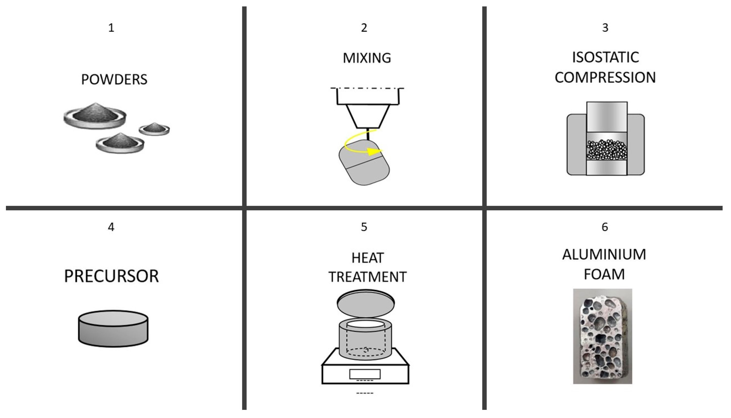
The production of closed cell aluminum foams using the powder compact melting method involves several steps, including powder preparation and mixing, compaction, melting, and foaming. A sketch of the production method is reported in
Figure 1. The manufacturing technique summarized here is described with major details in a previous work [
20]. In fact, many parameters affect the foaming process: composition of the powders, size, and shape of the stabilizer’s particles, powder mixing and conditions, temperature, and pressure during powder compaction, temperature of the oven, heating rate of the foam precursor, foaming time, atmosphere and pressure on the melt, and, finally, cooling rate to room temperature. Foam precursors have been prepared by using Al powder (purity 99.5%) with an average diameter of 45 μm, SiC particles with an average diameter of 37 μm and TiH
2 particles with an average diameter of 5 μm. Four set of samples have been produced by mixing together at room temperature different amounts of TiH
2 (0.2, 0.4 and 0.6 wt %) and SiC (2.8 and 6.0 wt %), as detailed in
Table 1. For each composition, 5 samples have been produced in order to check the repeatability of the process and, consequently, the morphological and mechanical properties; average properties have been reported. In the first step, aluminum (Al) powders are mixed with a blowing agent (Titanium Hydride) and a stabilizing agent (Silicon Carbide) to create a powder mixture [
21] in a rotating device whose distribution is as uniform as possible. This mixture is then compacted with a uniaxial pressure system under a load equal to 12 t. At the end of the compaction step, a manageable solid precursor is obtained. The precursor is then placed inside a copper crucible which must be oxidized in an oven at 700 °C before using it. After inserting the precursor in the crucible, the whole system is heated in a furnace up to a temperature above the melting point of aluminum, typically around 700–750 °C, depending also on the composition of the alloys. At this temperature, after a few minutes, the aluminum powders melt while the blowing agent releases gas (H
2), creating closed cells within the molten aluminum matrix. In the case of Al powders, the oven temperature was set at 700 °C, not much higher than the Al melting point (660 °C). This choice was driven by the melt viscosity being too low at higher temperatures. The precursors were heated to 700 °C in about 120 s in order to avoid an excessive gas dispersion before foaming. During the foaming process, the pressure inside the closed cells increases, causing the surrounding aluminum to expand and form the foam structure. The foaming process is carefully controlled from the top side of the oven monitoring the growth of the foam. The dwell time in the oven is critical for achieving the desired cell size, distribution, and density of the foam. Typically this time is in the range 4–6 min, depending on the mass of the employed powders. With shorter dwell time the growth of the foam is limited as well as porosity size, while with excessive longer times, coalescence between bubbles is the main problem, with the opposite problem that porosity size becomes excessive and consequently compromises the mechanical properties. When the foaming process is completed, the closed cell aluminum foam is cooled down in water. Four compositions have been investigated in the present study, derived from earlier studies [
14,
19,
20], focused on the detailed definition of the manufacturing process, as detailed in
Table 1.
2.2. Static Compression Tests on Foams
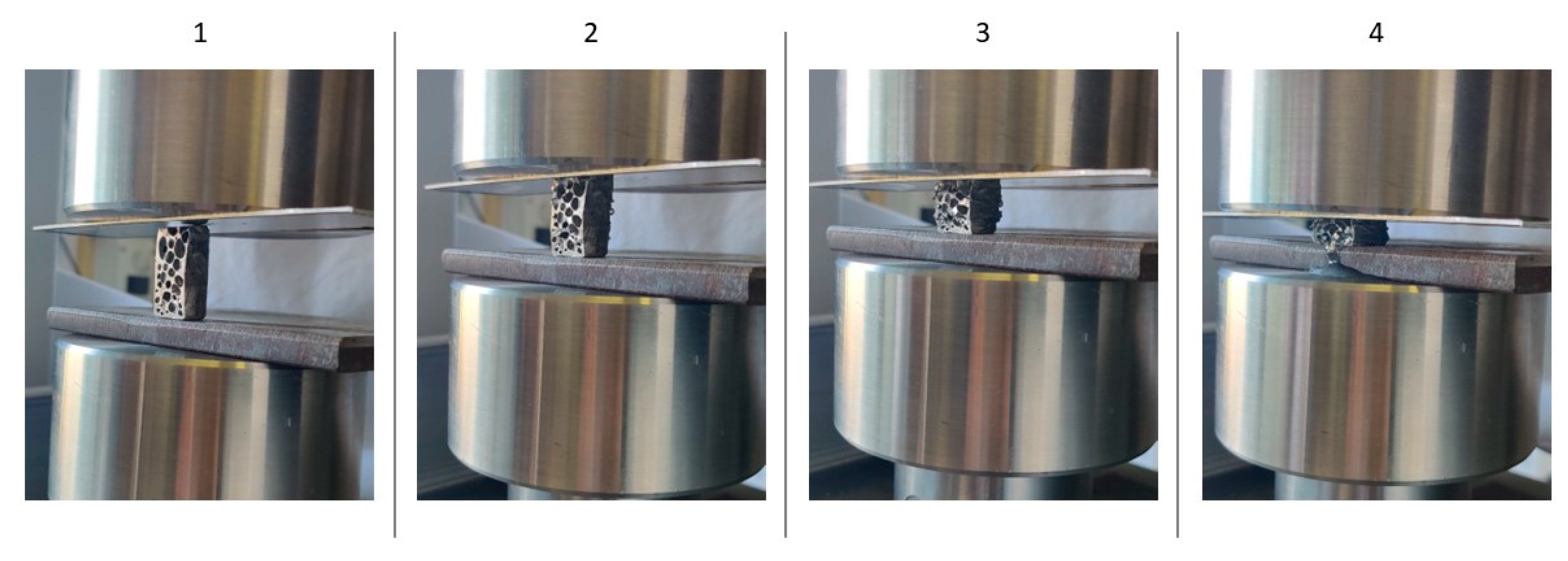
The static compression tests have been conducted using the MTS Insight 50 machine (Eden Praire, MN, USA), a standard tensile-compression machine, to determine the mechanical properties of materials. The compression testing process is carried out placing a specimen of the closed cell aluminum foam (ϕ = 16 mm of diameter) between two compression platens on the machine. A constant crosshead speed, 5 mm/min and 10 Hz, as the data sampling frequency has been selected (
Figure 2, 1–4) until the foam reaches the final densification. The load cell and displacement transducer of the machine record the load and deformation of the specimen, respectively. The complete compression curve is fundamental to finding the compressive strength, stiffness, and energy absorption capacity of the aluminum foam. The maximum compressive stress that the foam can withstand before final densification, the slope of the stress-strain curve at the pseudo-elastic region (indicative of the stiffness), and the area under the stress-strain curve (energy absorption capacity) up to the final densification are all recorded (
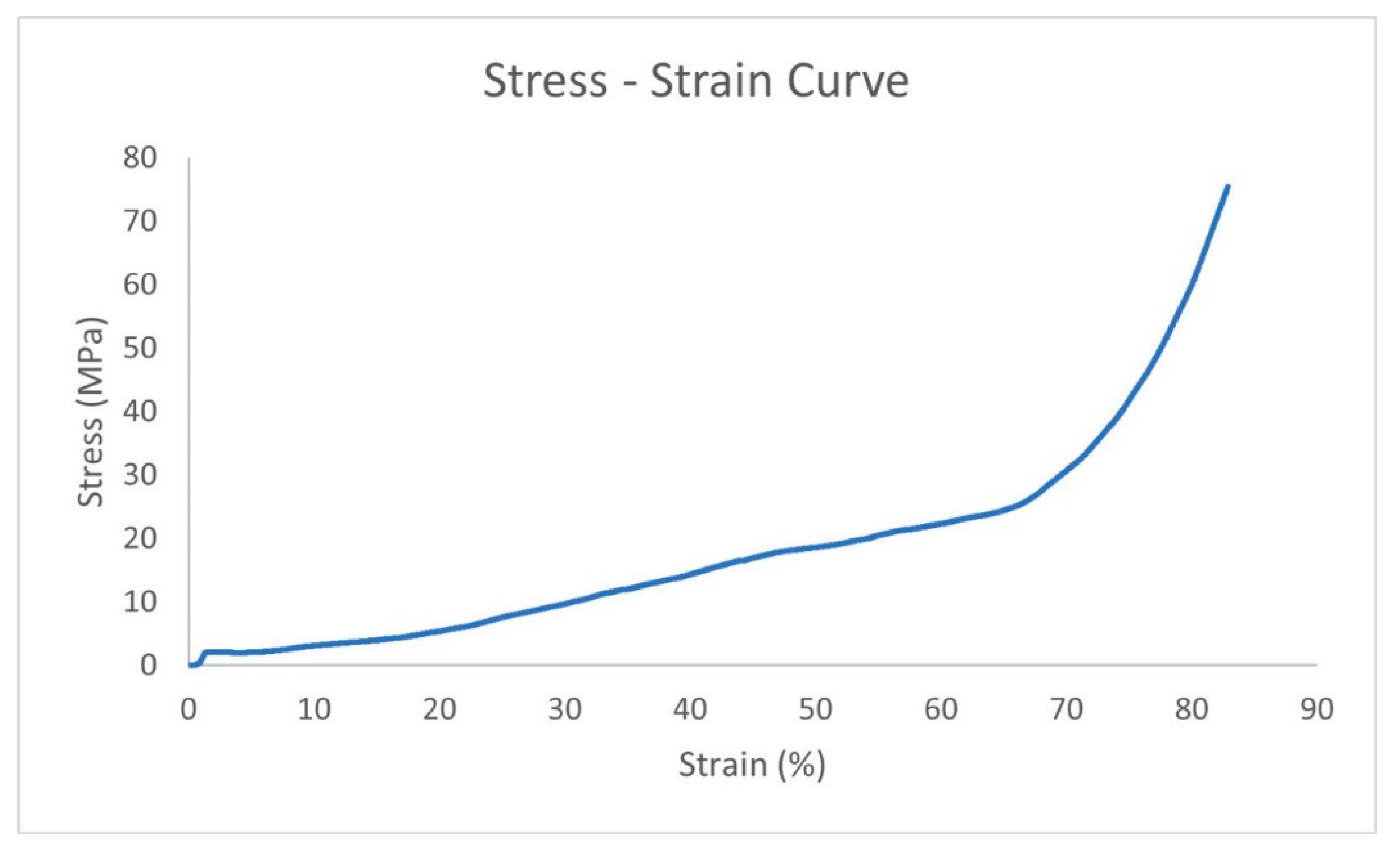
Figure 3). Five compression tests have been performed for each composition in order to investigate the repeatability of the process, too.
3. Results
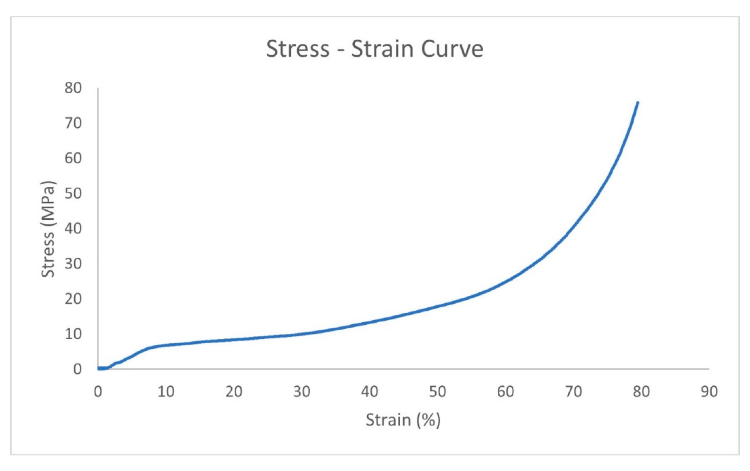
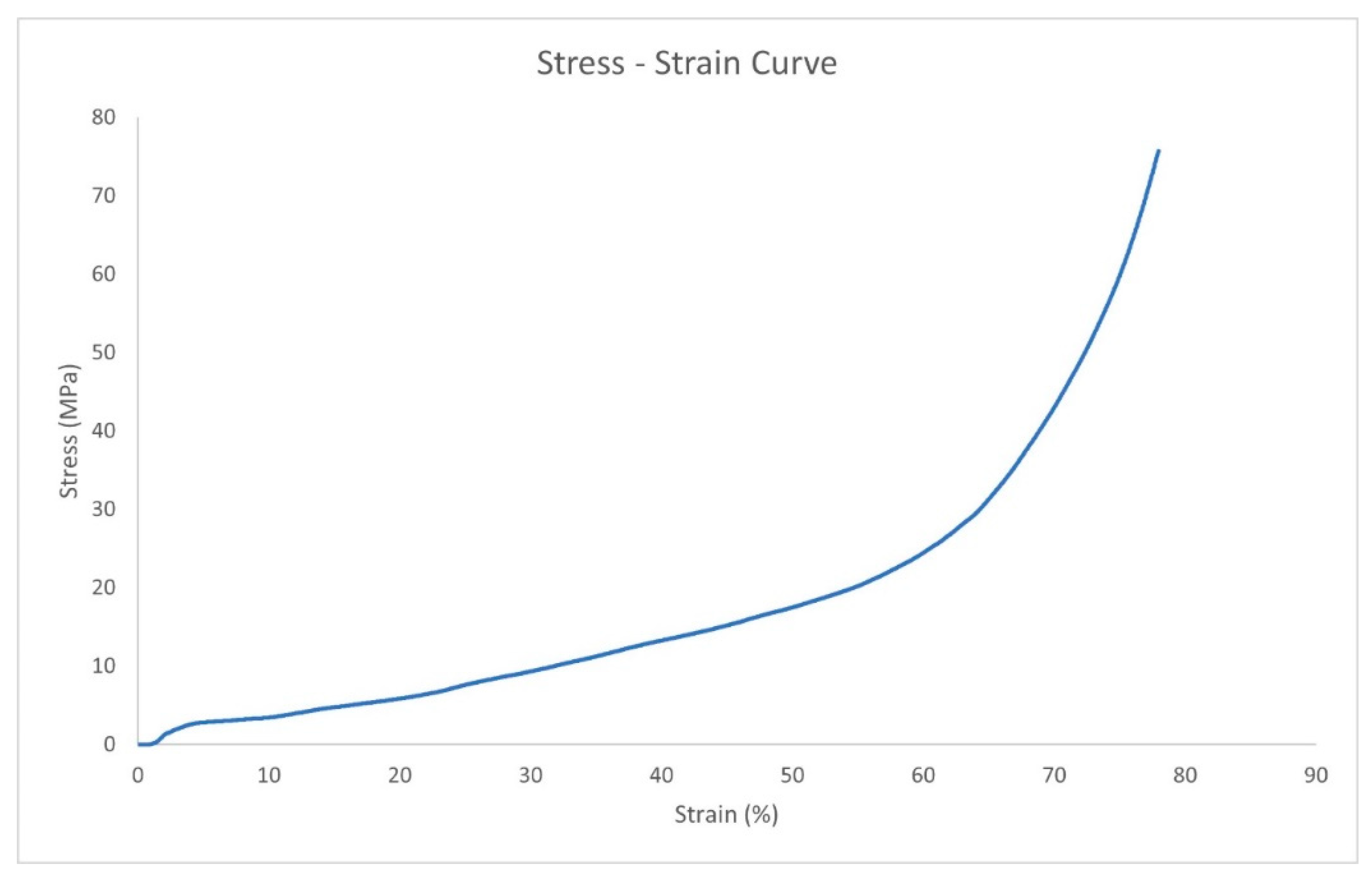
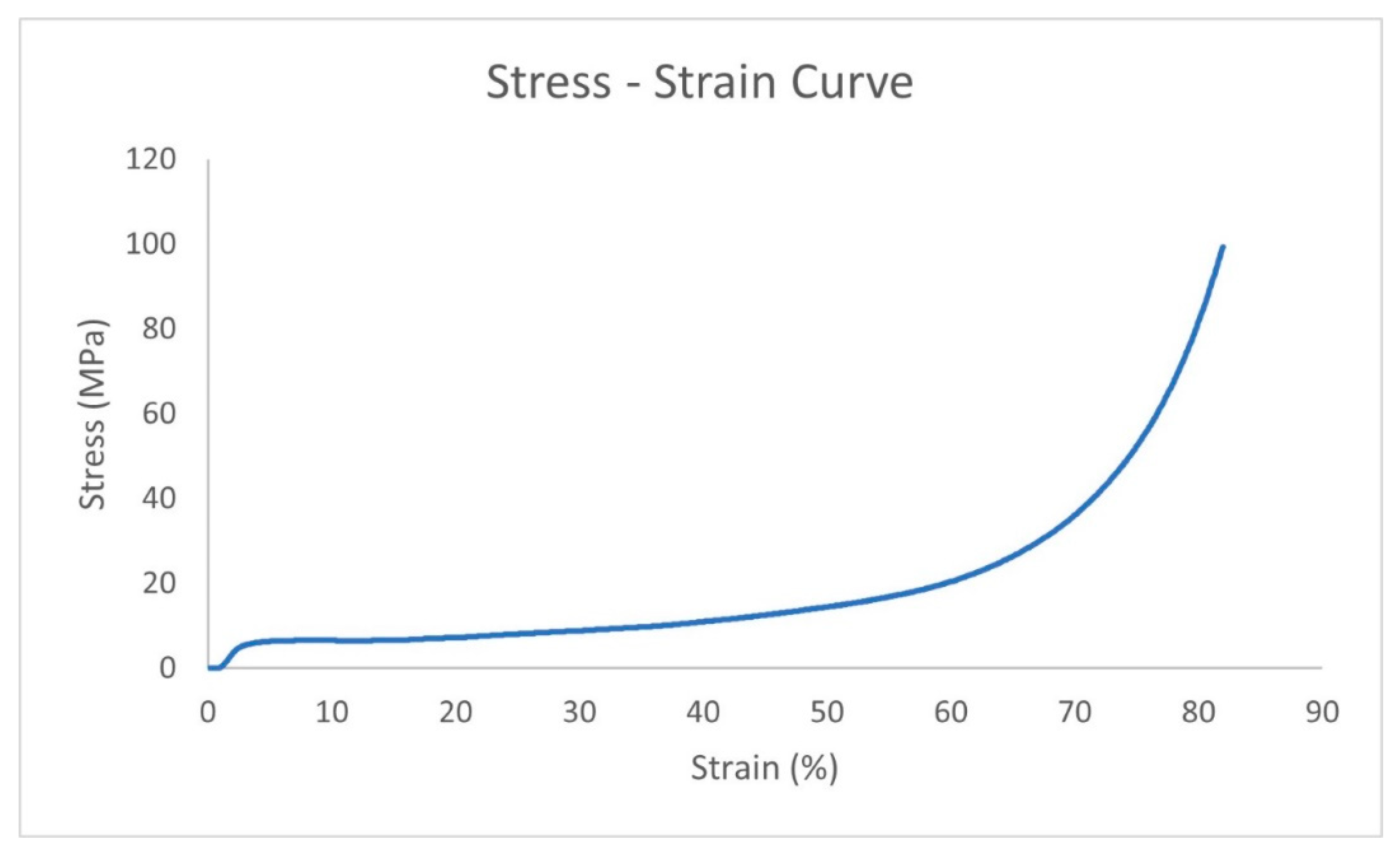
In this section, the main results coming from compression tests are presented and discussed. Some common features of all manufactured foams while subjected to compression tests (stress-strain curve) are reported below:
- (1)
A nearly linear pseudo-elastic stage in which stress and strain are almost linearly proportional is always present in all foams. However, limited and localized plastic deformations occur in the foam, hence the name “pseudo” elastic.
- (2)
The second stage of the curve is characterized by the presence of an extensive “plateau”, which is a widened part of the curve in which the stress is nearly constant while the material undergoes huge plastic strain. Microscopically, this stage is associated with the progressive plastic collapse of the cell walls.
- (3)
Once the porosities inside the foam totally collapsed, the material turns into the final stage of densification, which is characterized by a fast increase in the compressive load while only small deformation occurs.
In
Table 2,
Table 3,
Table 4 and
Table 5 compression test results (geometrical features and weight), respectively, for samples 1–4 are reported.
4. Strain Energy
Under the effect of the external applied load, Al foams undergo plastic deformations. The greatest part of the applied energy is heat dissipated, with a small amount is the storage in the material in the form of strain energy, and just a little amount is present in the form of residual stress. The strain energy stored in the pseudo-elastic stage is almost equal to the work conducted by an external force (work–energy theorem). Until the pseudo-elastic limit is reached, it can also be approximated by computing the area under the curve of the stress vs. strain graph.
According to Hooke’s law, for minor deformations of elastic materials, the strain is directly proportional to the applied stress. Hooke’s law only applies to minor deformations in an elastic material (up to the proportional limit) under the hypothesis of linear elasticity. Under plastic deformation, the strain energy density is the amount of strain energy per unit volume that is uniformly distributed inside a material. It can be determined by:
The ability of closed-cell aluminum foams to absorb energy improves as their relative density and strain rate increase [
14]. This improvement in energy absorption at high strain rates is promising for the application of closed-cell aluminum foams in high-impact energy absorption scenarios [
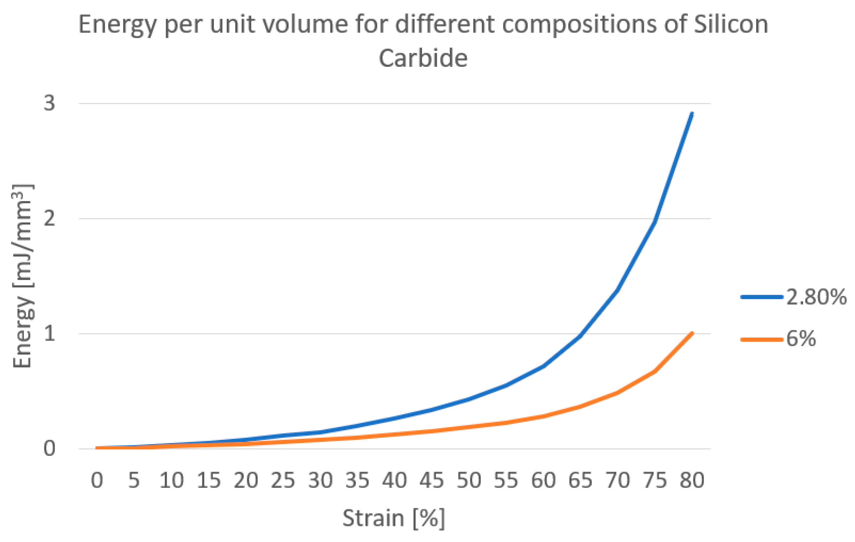
14]. By limiting the computation of absorbed energy up to 80% of the strain, the following results can be evidenced (
Table 7).
These results evidence that Sample 2 (SiC = 2.8%, TiH2 = 0.4% and Al = 96.8%) shows higher strain energy when compared to other samples. Metal foams with higher strain energy per unit volume have several advantages, including improved energy absorption, increased structural strength, enhanced thermal insulation, and improved sound absorption capabilities. They can absorb a greater energy amount, provide a high strength-to-weight ratio, slow down heat transfer, and offer better sound absorption, making them ideal for use in various applications such as impact protection, load-bearing structures, building insulation, heat exchangers, and noise control.
5. Image Analysis
Image analysis of closed cell aluminum foams is an important technique useful for understanding microstructure and porosity characteristics. Such properties are crucial for optimizing their performance in various applications. Image analysis can be used to quantify the porosity of the foam, which affects its insulation properties and structural performance. By analyzing the foam’s microstructure, image analysis can also provide insight into its strength, stiffness, and energy absorption capacity, which are critical factors in some applications, such as aerospace and automotive engineering. Image analysis can help identify defects and inconsistencies in the foam’s microstructure, allowing manufacturers to improve their production processes and quality control measurements. Furthermore, image analysis can aid in the development of new closed cell aluminum foam materials with tailored microstructures to meet specific application requirements. Image analysis also enables researchers to study the behavior of closed cell aluminum foams under different loading conditions, such as compression and impact, which can provide valuable insights for designing safer and more durable products. Finally, image analysis can be used to monitor the degradation of closed cell aluminum foams over time, helping to ensure their long-term performance and reliability in harsh environments.
Lucia ScMeas software (supplied by Nikon) is an image analysis tool which can extract useful information for research and commercial applications. The software has a wide range of image processing and analysis tools, capable of performing automated feature extraction, segmentation, object recognition, 3D volume rendering and visualization, and statistical analysis. Users can import images from various sources and pre-process them with image resampling, noise reduction, and contrast enhancement. The software can detect edges, lines, shapes, and regions of interest in the image and perform object recognition by training the software to recognize specific objects or patterns. It also provides statistical analysis tools, including image statistics, correlation, and regression analysis.
5.1. Foam Properties: Circularity and Porosity
Circularity is a crucial characteristic of closed cell aluminum foam that affects their performance in various applications. A high degree of circularity enhances the strength, stiffness, thermal, and acoustic insulation properties of the foam by providing uniform cell shapes that distribute loads evenly. This makes it ideal for lightweight structural applications and thermal management in electronics. Low circularity can lead to irregular cell shapes, resulting in an uneven distribution of loads and an increased risk of failure. In industries such as aerospace and automotive, a high degree of circularity is essential for the foam’s performance and reliability.
Porosity is an important characteristic of closed cell aluminum foams that affect their performance in various applications, alongside circularity. The low porosity size provides excellent insulation, strength, and stiffness, as well as durability and resistance to moisture, chemicals, and UV exposure. These benefits make closed cell aluminum foams a popular choice for a wide range of applications in which weight reduction, thermal insulation, and acoustic insulation are critical factors. Closed cell aluminum foams offer improved strength and stiffness compared to open cell foams due to the enclosed cells providing structural support to the material. Low porosity also prevents the loss of moisture and other contaminants, which can cause corrosion and degradation of the foam over time. In the following paragraph, a systematic comparison is performed on the area, circularity, and equivalent diameter as a function of the content of TiH
2 and SiC in
Figure 9,
Figure 10,
Figure 11,
Figure 12,
Figure 13 and
Figure 14.
5.2. Image Analysis Results
These results show that Sample 4 (SiC = 6%, TiH2 = 0.2% and Al = 93.8%) exhibits optimal geometrical properties of foams from the point of view of the morphological shape and size of the porosity. Metal foams with the highest circularity and the most uniform equivalent diameter and area show uniform properties, allowing for more predictable behavior in various applications. They also have better mechanical properties, with a more regular plateau due to efficient load transfer, including compressive strength and energy absorption. Overall, these foams offer a range of benefits, including improved properties and increased surface area.
6. Discussion
The study of metal foams has received increasing interest in recent years due to their unique properties, such as high strength-to-weight ratio, excellent energy absorption capacity, and acoustic insulation. Metal foams have potential applications in several industries, including aerospace, automotive, and biomedical. Therefore, it is useful to understand their physical properties and how they can be modified to enhance their performance.
The compression test is a standard method utilized to assess the mechanical properties of foam. In this work, the foams have been compressed up to a specific strain level, and the force required to achieve that strain has been measured. The compression test provides insights into the foam’s compressive strength and energy absorption capacity.
The experimental analysis performed in this work is based primarily on closed-cell aluminum foams. The composition of such materials has been changed in order to get four different types of samples. After the compression tests, the strain energy was evaluated, and sample 2 showed the highest strain energy per unit volume.
The analysis of morphological properties, such as area, circularity, and equivalent diameter, can provide a better understanding of the foam’s structure and porosity, parameters which can be manipulated to enhance the foam’s properties for specific applications, both structural and functional. In this work, the foams have been analyzed from a morphological point of view: physical properties of the foams, such as area, circularity, and equivalent diameter, were determined using image analysis software. This analysis was conducted on all four samples and the main results are discussed in the following.
From the comparison of
Figure 9,
Figure 10,
Figure 11,
Figure 12,
Figure 13 and
Figure 14, it has been found that the geometrical features (area, circularity, and equivalent diameter) of the porosity critically depend, at first glance, on the TiH
2 content. In general, foams manufactured with 0.2% TiH
2 show pores of smaller size and homogeneous size in comparison with the ones produced with 0.4% and 0.6% of TiH
2 (
Figure 9). With increasing TiH
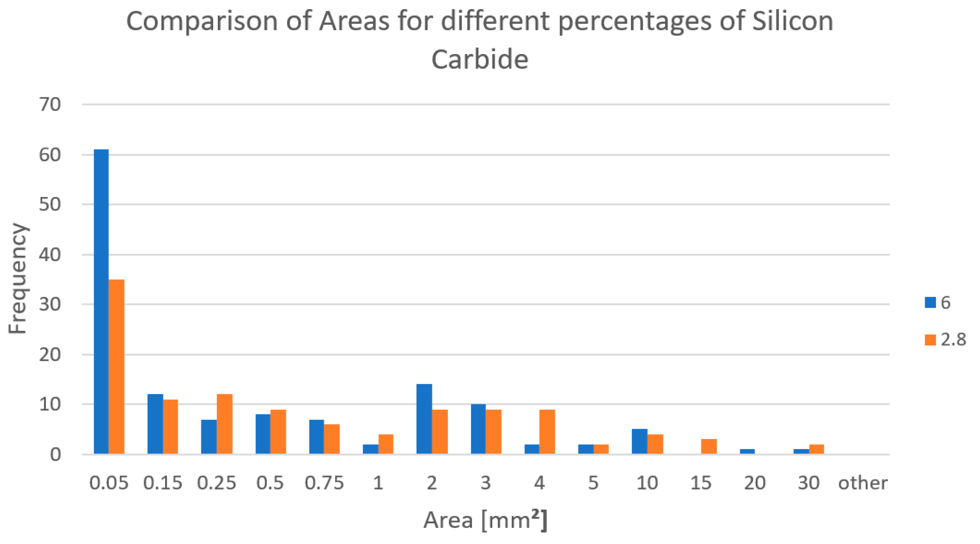
2 content the bubble’s size raises too and a greater dispersion of the porosity size has been evidenced. The consequence of increasing SiC content is shown in
Figure 10, where the stabilizing effect of the ceramic particles is particularly evident in the smallest range of area (0–0.05 mm
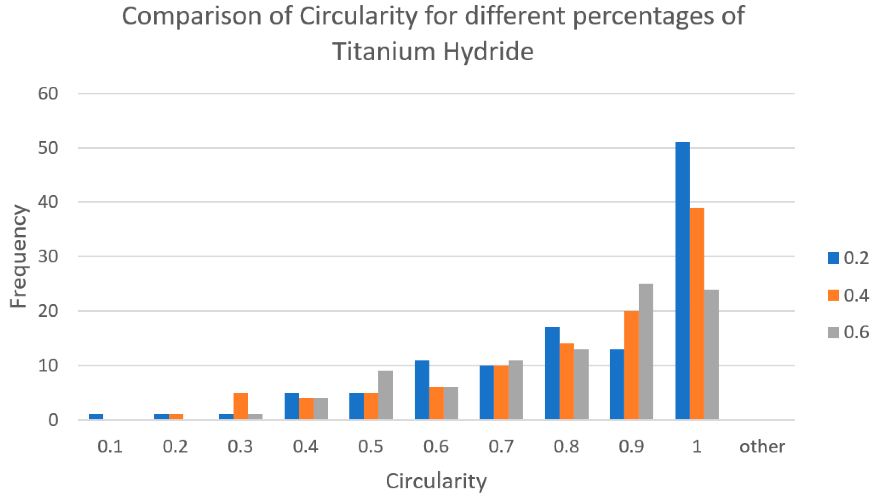
2). Dealing with circularity, it has been found that the highest values are achieved with the lower content of TiH
2 (
Figure 11) and with the higher content of SiC (
Figure 12). As concerns the equivalent diameter, it is reflected in the situation of the area illustrated in
Figure 9 and
Figure 10. The effect of the addition of TiH
2 increases porosity size and consequently the equivalent diameter (
Figure 13) while the stabilizing effect of SiC addition has the greatest impact on the smaller porosity size (
Figure 14). The distribution of particles on the walls between adjacent porosities contribute to the stabilization of the foam structure, reducing drainage of molten metal and increasing the resistance to metal flow. In this way, thinning of the walls is prevented, wall strength is enhanced, and, in general, mechanical strength is increased.
The analysis of the absorbed energy per unit of volume (specific energy) with a different amount of TiH
2 (
Figure 7) evidenced that absorbed energy increases from 0.2% to 0.4% TiH
2 and decreases from 0.4% to 0.6% of TiH
2. The main reason for that can be ascribed to the contribution due to the lower plateau stress and higher strain found with increasing content of TiH
2. The specific energy is the area below the curve σ-ε, so the opposite contribution due to stress and strain are evident from these results. The combination of higher stress and lower strain as well lower stress and higher strain is the reason for the smaller specific absorbed energy, while average values of stress and strain allow the highest specific absorbed energy to be obtained.
7. Conclusions and Future Outlook
In conclusion, relative to the investigation on the analyzed compositions, it can be deduced that:
- (1)
From the compression tests and foam property measurements, sample 2, containing SiC = 2.8%, TiH2 = 0.4% and Al = 96.8%, has the highest energy absorption.
- (2)
Sample 4, containing SiC = 6%, TiH2 = 0.2% and Al = 93.8%, exhibited good morphological properties overall.
- (3)
Higher TiH2 content involves greater areas of the pores and consequently average diameter, but, at the same time, a greater dispersion of the porosity has been evidenced.
- (4)
Higher SiC content involves an effect of stabilization on the porosity and consequently on the circularity and the equivalent diameter.
- (5)
Specific energy absorption is strictly correlated to the morphology of the stress-strain curve and the contribution of both. The combination of higher stress and lower strain as well lower stress and higher strain is the reason for the smaller specific absorbed energy while average values of stress and strain allow the highest specific absorbed energy to be obtained.
- (6)
In general, the combined use of mechanical characterization and image analysis can aid in the development of a new kind of closed cell aluminum foam materials with tailored microstructures to meet specific application requirements. Image analysis also enables researchers to study the behavior of closed cell aluminum foams under different loading conditions, such as compression and impact, which can provide valuable insights for designing safer and more durable products or materials with customized deformation properties and energy absorption.
- (7)
Low weight and energy absorption capability but also thermal properties in heat dissipation can be exploited in further possible applications.
In the future, further developments may regard a systematic investigation with a greater amount of blowing agent and stabilizing agent, different base metals, and alloys in order to extend relevant results to other materials and the morphology of porosity.
Author Contributions
Conceptualization, G.C. and M.E.T.; methodology, M.B., G.C. and M.E.T.; software, M.B.; formal analysis, M.B.; investigation, M.B., G.C. and M.E.T.; resources, M.B., G.C. and M.E.T.; data curation, M.B., G.C. and M.E.T.; writing—original draft preparation, M.B.; writing—review and editing, M.B., G.C. and M.E.T.; visualization, M.B., G.C. and M.E.T.; supervision, M.B., G.C. and M.E.T. All authors have read and agreed to the published version of the manuscript.
Funding
This research received no external funding.
Institutional Review Board Statement
Not applicable.
Data Availability Statement
No new data were created.
Acknowledgments
Authors are grateful to Benedetto Iacovone and Piero Plini for the technical support in the experimental tests.
Conflicts of Interest
The authors declare no conflict of interest.
References
- Banhart, J. Manufacture, characterization and application of cellular metals and metal foams. Prog. Mater. Sci. 2001, 46, 559–632. [Google Scholar] [CrossRef]
- Costanza, G.; Tata, M.E.; Trillicoso, G. Al foams manufactured by PLA replication and sacrifice. Int. J. Light. Mater. Manuf. 2021, 4, 62–66. [Google Scholar] [CrossRef]
- Rajak, D.K.; Gupta, M. Applications of metallic foams. In An Insight into Metal Based Foams. Advanced Structured Materials; Springer: Berlin/Heidelberg, Germany, 2020; Volume 145. [Google Scholar] [CrossRef]
- Costanza, G.; Mantineo, F.; Missori, S.; Sili, A.; Tata, M.E. Characterization of the compressive behaviour of an Al foam by X-ray computerized tomography. In Light Metals 2012; TMS: Pittsburgh, PA, USA, 2012; pp. 533–536. [Google Scholar] [CrossRef]
- Ensarioglu, C.; Bakirci, A.; Koluk, H.; Cakir, M.C. Metal foams and their applications in aerospace components. In Materials, Structures and Manufacturing for Aircraft; Springer: Berlin/Heidelberg, Germany, 2022; pp. 27–63. [Google Scholar] [CrossRef]
- Sharma, S.S.; Yadaw, S.; Joshi, A.; Goyal, A.; Khatri, R. Application of metallic foam in vehicle structure: A review. Mater. Today Proc. 2022, 63, 347–353. [Google Scholar] [CrossRef]
- Singh, S.; Bhatnagar, N. A survey of fabrication and application of metallic foams. J. Porous Mater. 2018, 25, 537–554. [Google Scholar] [CrossRef]
- Brugnolo, F.; Costanza, G.; Tata, M.E. Manufacturing and characterization of AlSi foams as core materials. Proc. Eng. 2015, 109, 219–227. [Google Scholar] [CrossRef]
- Kim, S.; Lee, C.W. A review of manufacturing and application of open-cell metal foam. Proc. Mater. Sci. 2014, 4, 305–309. [Google Scholar] [CrossRef]
- Sutygina, A.; Betke, U.; Hasemann, G.; Scheffler, M. Manufacturing of open-cell metal foams by the sponge replication technique. IOP Conf. Ser. Mater. Sci. Eng. 2020, 882, 012022. [Google Scholar] [CrossRef]
- Costanza, G.; Dodbiba, G.; Tata, M.E. Optimization of the process parameters for the manufacturing of open-cells iron foams with high energy absorption. Proc. Struct. Int. 2016, 2, 2277–2282. [Google Scholar] [CrossRef]
- Costanza, G.; Tata, M.E. Parameters affecting energy absorption in metal foams. Mater. Sci. Forum 2018, 941, 1552–1557. [Google Scholar] [CrossRef]
- Onck, P.R.; Van Merkerk, R.; Raaijmakers, A.; De Hosson, J.T.M. Fracture of open and closed- cell metal foams. J. Mater. Sci. 2005, 40, 5821–5828. [Google Scholar] [CrossRef]
- Costanza, G.; Giudice, F.; Sili, A.; Tata, M.E. Correlation Modeling between Morphology and Compression Behavior of Closed-Cell Al Foams Based on X-ray Computed Tomography Observations. Metals 2021, 11, 1370. [Google Scholar] [CrossRef]
- Costanza, G.; Tata, M.E. Mechanical behavior of PCMT and SDP Al foams: A comparison. Proc. Struct. Integ. 2020, 25, 55–62. [Google Scholar] [CrossRef]
- Costanza, G.; Tata, M.E. Dynamic and static behaviour of aluminium foam. In Proceedings of the 4th International Structural Engineering and Construction Conference, ISEC-4—Innovations in Structural Engineering and Construction, Melbourne, Australia, 26–28 September 2007; Volume 2, pp. 919–922. [Google Scholar]
- Shi, J.; Du, H.; Chen, Z.; Lei, S. Review of phase change heat transfer enhancement by metal foam. Appl. Therm. Eng. 2023, 219 Pt B, 11947. [Google Scholar] [CrossRef]
- Hu, H.; Zao, Y.; Li, Y. Research progress on flow and heat transfer characteristics of fluids in metal foams. Renew. Sustain. Energy Rev. 2023, 171, 113010. [Google Scholar] [CrossRef]
- Costanza, G.; Montanari, R.; Tata, M.E. Optimization of TiH2 content in Al foams. Metall. Ital. 2005, 97, 41–47. [Google Scholar]
- Costanza, G.; Gusmano, G.; Montanari, R.; Tata, M.E.; Ucciardello, N. Effect of powder mix composition on Al foam morphology. Proc. Inst. Mech. Eng. Part L J. Mater. Des. Appl. 2008, 222, 131–140. [Google Scholar] [CrossRef]
- Kennedy, R. Porous metals and metal foams made from powders. In Powder Metallurgy; IntechOpen Limited: London, UK, 2012; pp. 31–46. [Google Scholar] [CrossRef]
Figure 1.
Sketch of the production process of closed-cell Al foams.
Figure 1.
Sketch of the production process of closed-cell Al foams.
Figure 2.
Compression stages of Al foam: (1) before the test, (2) at the end of the pseudo-elastic stage, (3) at the end of the plateau stress, (4) after final densification.
Figure 2.
Compression stages of Al foam: (1) before the test, (2) at the end of the pseudo-elastic stage, (3) at the end of the plateau stress, (4) after final densification.
Figure 3.
Stress–strain curve for sample 1 (0.2% TiH2, 2.8% SiC).
Figure 3.
Stress–strain curve for sample 1 (0.2% TiH2, 2.8% SiC).
Figure 4.
Stress–strain curve for sample 2 (0.4% TiH2, 2.8% SiC).
Figure 4.
Stress–strain curve for sample 2 (0.4% TiH2, 2.8% SiC).
Figure 5.
Stress–strain curve for sample 3 (0.6% TiH2, 2.8% SiC).
Figure 5.
Stress–strain curve for sample 3 (0.6% TiH2, 2.8% SiC).
Figure 6.
Stress–strain curve for sample 4 (0.2% TiH2, 6% SiC).
Figure 6.
Stress–strain curve for sample 4 (0.2% TiH2, 6% SiC).
Figure 7.
Energy per unit volume for different compositions of TiH2.
Figure 7.
Energy per unit volume for different compositions of TiH2.
Figure 8.
Energy per unit volume for different compositions of SiC.
Figure 8.
Energy per unit volume for different compositions of SiC.
Figure 9.
Comparison of distribution of area for different compositions of TiH2.
Figure 9.
Comparison of distribution of area for different compositions of TiH2.
Figure 10.
Comparison of distribution of area for different amount of SiC.
Figure 10.
Comparison of distribution of area for different amount of SiC.
Figure 11.
Comparison of distribution of circularity for different amount of TiH2.
Figure 11.
Comparison of distribution of circularity for different amount of TiH2.
Figure 12.
Comparison of distribution of circularity for different amount of SiC.
Figure 12.
Comparison of distribution of circularity for different amount of SiC.
Figure 13.
Comparison of distribution of equivalent diameter for different amount of TiH2.
Figure 13.
Comparison of distribution of equivalent diameter for different amount of TiH2.
Figure 14.
Comparison of distribution of equivalent diameter for different amount of SiC.
Figure 14.
Comparison of distribution of equivalent diameter for different amount of SiC.
Table 1.
Composition (wt %) of the manufactured Al foams.
Table 1.
Composition (wt %) of the manufactured Al foams.
| Sample | Al (%) | TiH2 (%) | SiC (%) |
|---|
| 1 | 97.0 | 0.2 | 2.8 |
| 2 | 96.8 | 0.4 | 2.8 |
| 3 | 96.6 | 0.6 | 2.8 |
| 4 | 93.8 | 0.2 | 6.0 |
Table 2.
Properties of sample 1 (0.2% TiH2, 2.8% SiC) before and after compression.
Table 2.
Properties of sample 1 (0.2% TiH2, 2.8% SiC) before and after compression.
| | Before Compression | After Compression |
|---|
| Weight (g) | 5.8 | 3.9 |
| Diameter (mm) | 16 | 21 |
| Height (mm) | 28 | 7 |
Table 3.
Properties of sample 2 (0.4% TiH2, 2.8% SiC) before and after compression.
Table 3.
Properties of sample 2 (0.4% TiH2, 2.8% SiC) before and after compression.
| | Before Compression | After Compression |
|---|
| Weight (g) | 5.8 | 3.7 |
| Diameter (mm) | 16 | 20 |
| Height (mm) | 30 | 7 |
Table 4.
Properties of sample 3 (0.6% TiH2, 2.8% SiC) before and after compression.
Table 4.
Properties of sample 3 (0.6% TiH2, 2.8% SiC) before and after compression.
| | Before Compression | After Compression |
|---|
| Weight (g) | 7.6 | 6.0 |
| Diameter (mm) | 16 | 21 |
| Height (mm) | 45 | 9 |
Table 5.
Properties of sample 4 (0.2% TiH2, 6% SiC) before and after compression.
Table 5.
Properties of sample 4 (0.2% TiH2, 6% SiC) before and after compression.
| | Before Compression | After Compression |
|---|
| Weight (g) | 4.4 | 3.0 |
| Diameter (mm) | 14 | 18 |
| Height (mm) | 16 | 4 |
Table 6.
Compression test data for each sample.
Table 6.
Compression test data for each sample.
| Sample | Plateau Stress (MPa) | Maximum Strain (%) | Maximum Energy per Unit Volume (mJ/mm3) |
|---|
| 1 | 9.2 | 79.5 | 2.9 |
| 2 | 7.6 | 78.0 | 5.9 |
| 3 | 7.5 | 82.9 | 5.0 |
| 4 | 10.3 | 81.4 | 1.0 |
Table 7.
Energy per unit volume at 80% of strain for each sample.
Table 7.
Energy per unit volume at 80% of strain for each sample.
| Sample | Energy per Unit Volume (mJ/mm3) at 80% Strain |
|---|
| 1 | 2.9 |
| 2 | 5.9 |
| 3 | 3.9 |
| 4 | 1.0 |
| Disclaimer/Publisher’s Note: The statements, opinions and data contained in all publications are solely those of the individual author(s) and contributor(s) and not of MDPI and/or the editor(s). MDPI and/or the editor(s) disclaim responsibility for any injury to people or property resulting from any ideas, methods, instructions or products referred to in the content. |
© 2023 by the authors. Licensee MDPI, Basel, Switzerland. This article is an open access article distributed under the terms and conditions of the Creative Commons Attribution (CC BY) license (https://creativecommons.org/licenses/by/4.0/).
