

A Millimeter-Wave Radar Tunnel Obstacle Detection Method Based on Invalid Target Filtering

Abstract
:1. Introduction
2. Materials and Methods
2.1. Software, Hardware, and Information Acquisition
2.2. Theoretical Framework
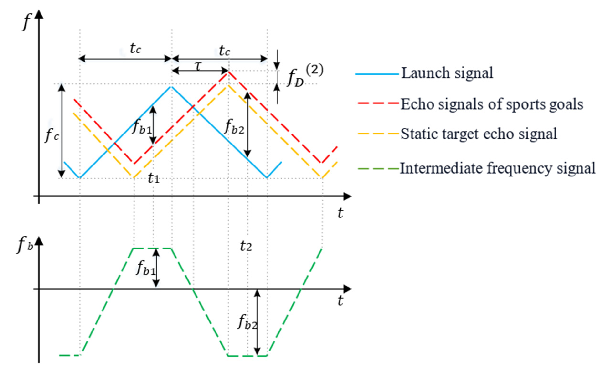
2.2.1. Principle of Millimeter-Wave Radar Target Detection
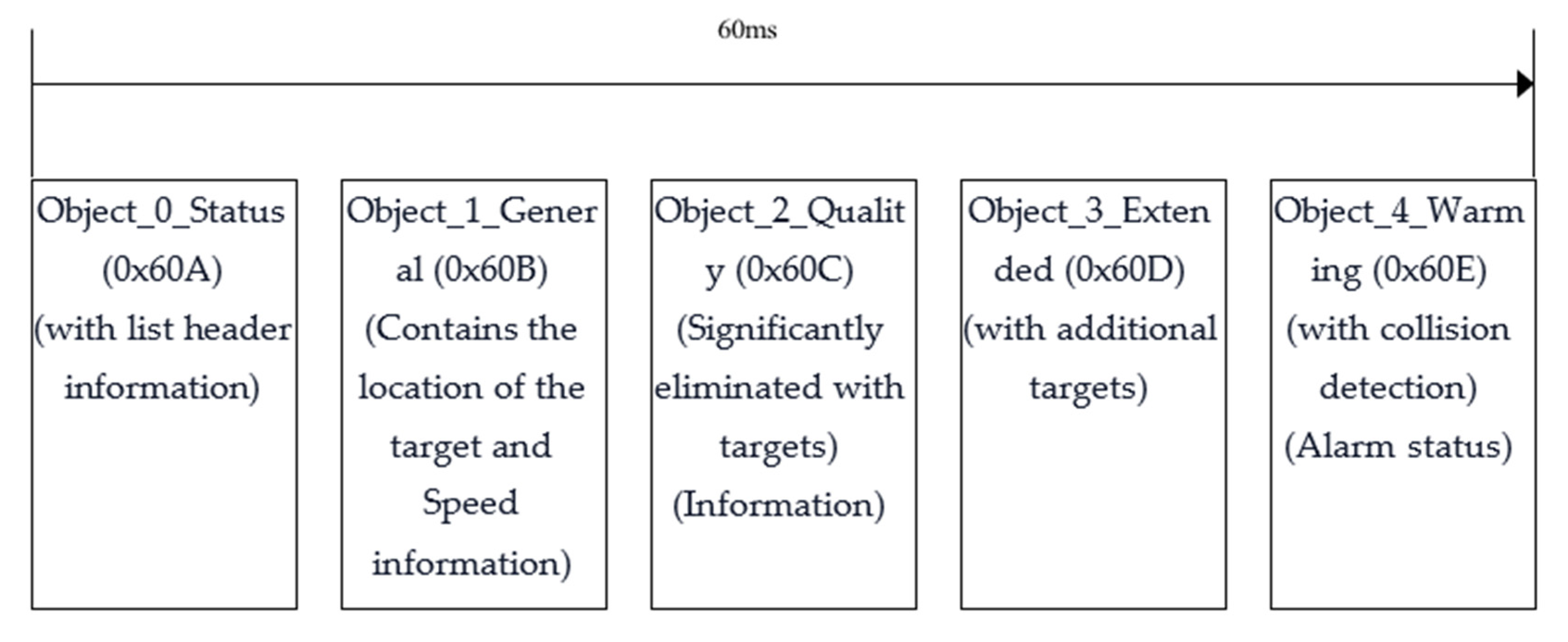
2.2.2. CAN Message
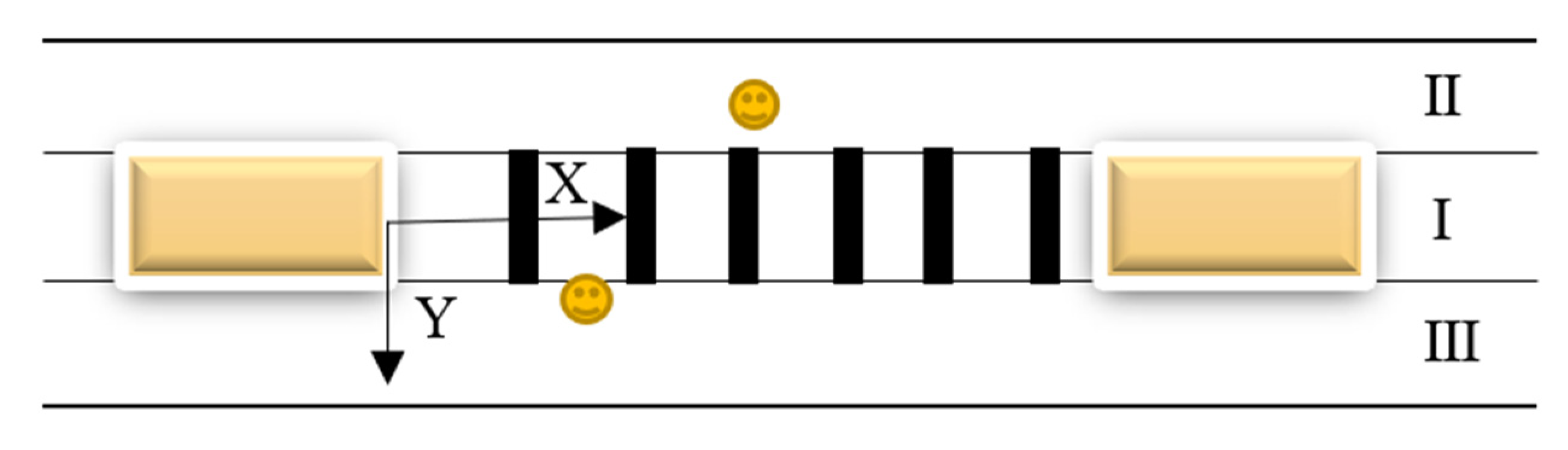
2.3. Target Model
2.3.1. Object_1_General Message Segment
2.3.2. Object_3_Extended Message Segment
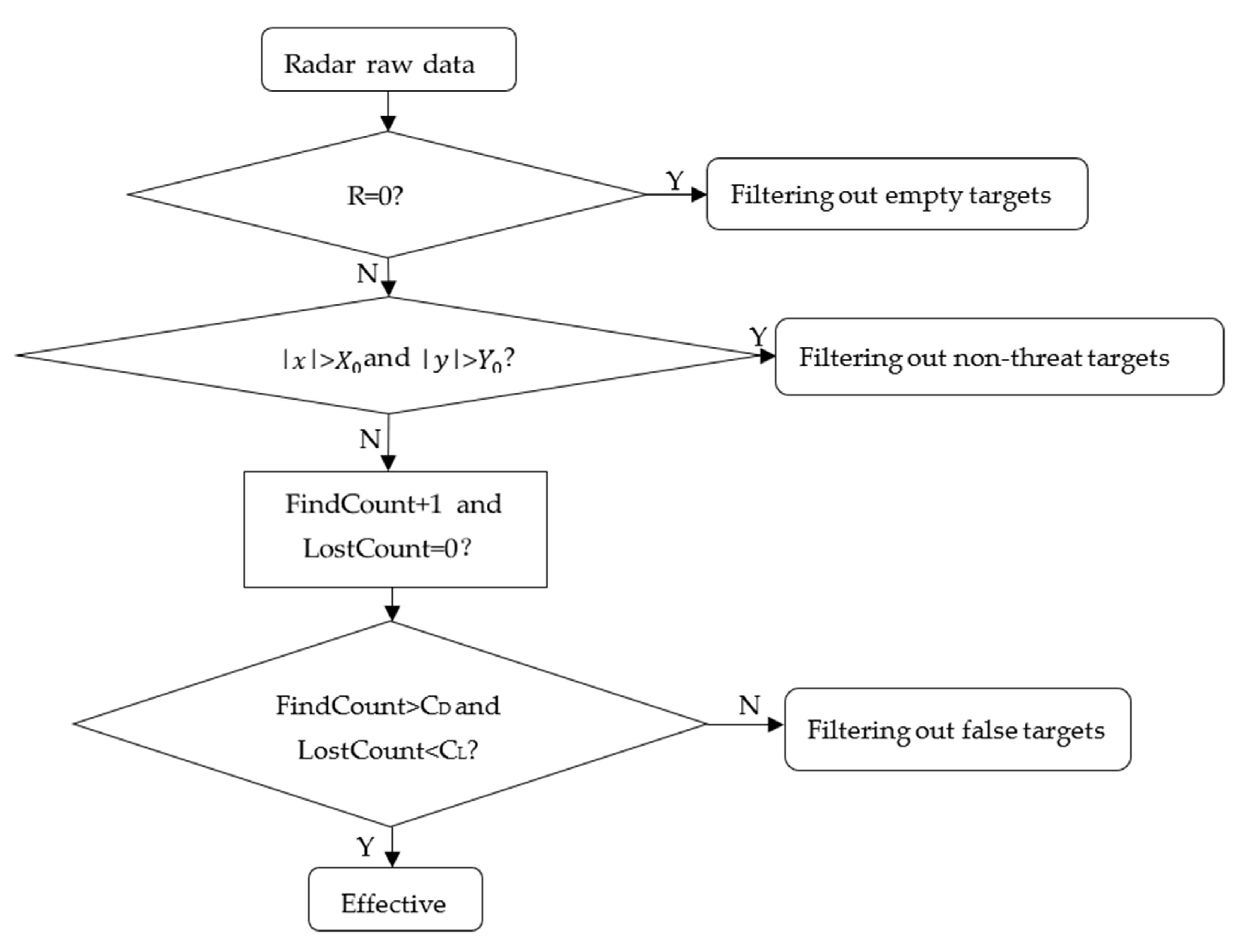
2.4. Filtering Methods for Invalid Millimeter-Wave Radar Targets
3. Test and Result Analysis
3.1. Performance Test of Filtering Algorithm for Invalid Targets
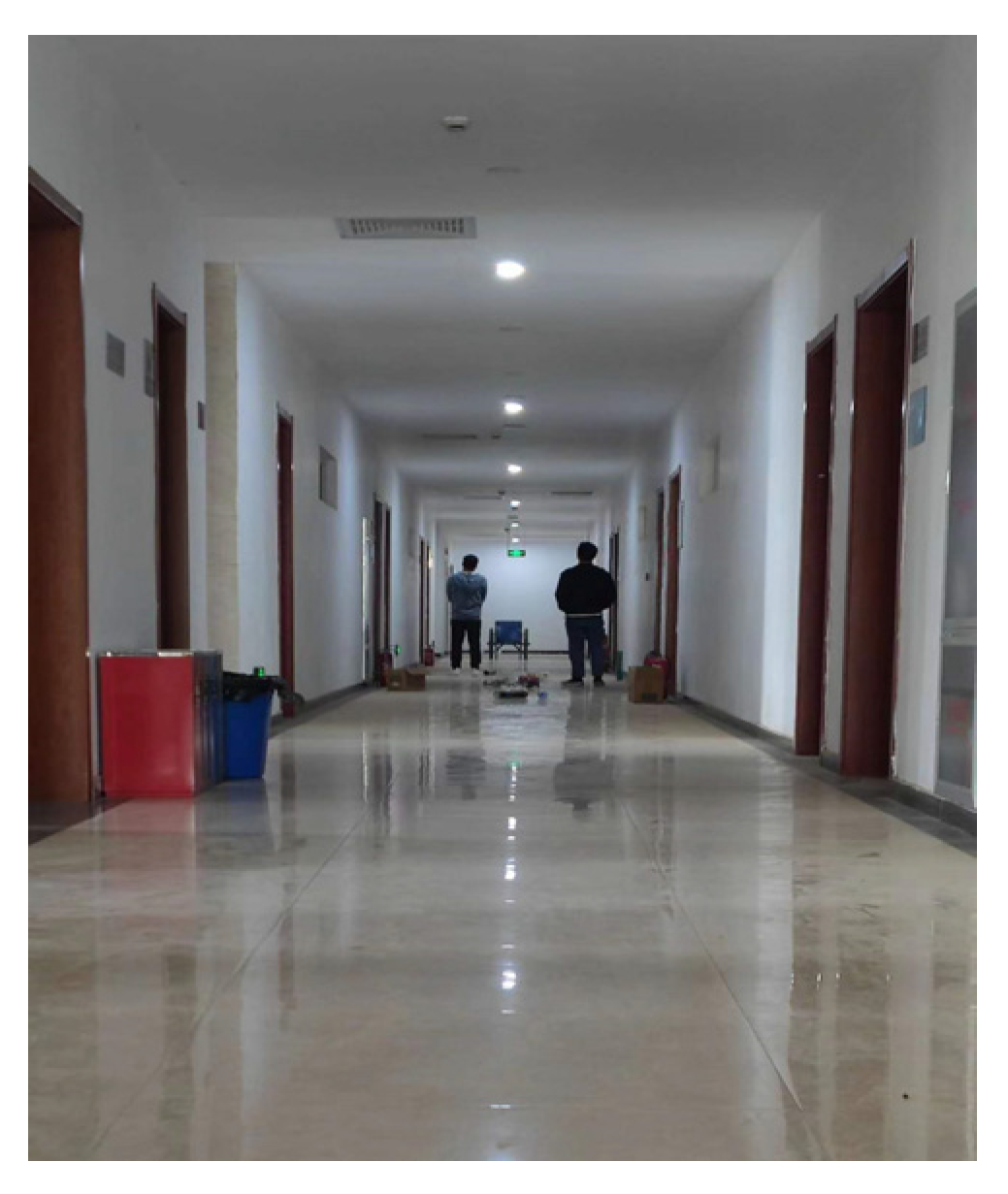
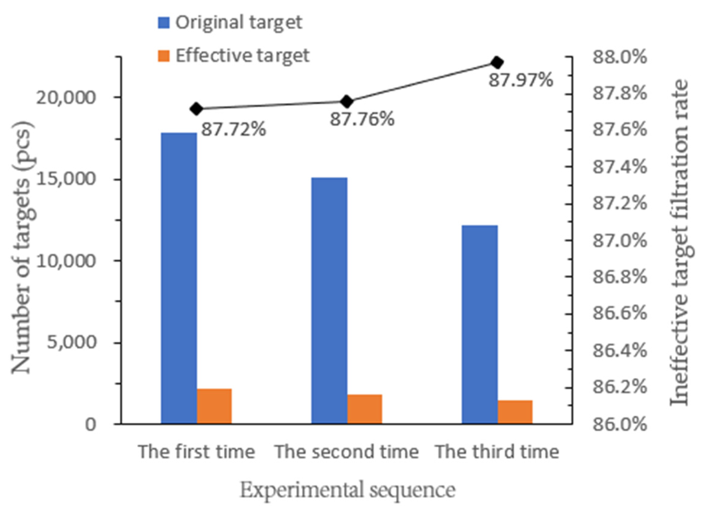
3.1.1. Car at a Standstill
3.1.2. The Vehicle Was Running in a Straight Line under the Smooth Road Surface
3.1.3. The Vehicle Was Driving on an Uneven Road Surface
3.2. Comparison of the Filtering Rate of Invalid Targets in Different States
4. Conclusions
Author Contributions
Funding
Data Availability Statement
Conflicts of Interest
References
- Yu, Q.X.; Zhang, Y.S. Track obstacle intelligent recognition technology of mine electric locomotive based on image processing. Metal Mine 2021, 8, 150–157. [Google Scholar]
- Han, J.H.; Wei, X.; Lu, Y.; Wen, Z.; Cheng, Y.A.; Cheng, L. Driverless technology of underground locomotive in coal mine. J. China Coal Soc. 2020, 45, 2104–2115. [Google Scholar]
- Chen, Y.Y.; Huo, Z.L.; Liu, Z.W.; Zhang, Y.H. Development trend and key technology of coal mine transportation robot in China. Coal Sci. Technol. 2020, 48, 233–242. [Google Scholar]
- Chen, X.M.; Wang, E.B.; Wang, G. Research on electric locomotive self-driving technology in coal mine. Coal Sci. Technol. 2020, 48, 159–164. [Google Scholar]
- Liu, M.; Chen, J.; Zhao, X.; Wang, L.; Tian, Y. Dynamic obstacle detection based on multi-sensor information fusion. IFAC Pap. Line 2018, 51, 861–865. [Google Scholar]
- Wang, H.; Xu, Y.S.; Cai, Y.F.; Chen, L. Overview of intelligent vehicle multi-target detection technology based on multi-sensor fusion. J. Automot. Saf. Energy 2021, 12, 440–455. [Google Scholar]
- Guo, Y.C.; Tong, J.L.; Wang, S. Research on multi-object detection in driving scene of underground unmanned electric locomotive. J. Mine Autom. 2022, 48, 56–63. [Google Scholar]
- Wang, J.H.; Wang, L.G.; Bi, L. Obstacle Detection Technology of Mine Electric Locomotive Driverless Based on Computer Vision Technology. Gold Sci. Technol. 2021, 29, 136–146. [Google Scholar]
- Yang, X.; Ma, B.; Wang, J.S.; Zhu, M.Q. Obstacle detection and ranging method of mine locomotive based on monocular vision. Ind. Mine Autom. 2014, 40, 96–99. [Google Scholar]
- Guo, Y.C.; Yang, T.; Wang, S. Research on Multi-Object Real-Time Detection of Mine Electric Locomotive Based on Improved YOLOv4-Tiny. Adv. Eng. Sci. 2023, 1–11. Available online: https://jsuese.ijournals.cn/jsuese_cn/ch/reader/view_abstract.aspx?flag=2&file_no=202201070000003&journal_id=jsuese_cn#:~:text=Firstly%2C%20in%20order%20to%20improve%20the%20detection%20ability,by%20K-means%20and%20K-means%2B%2B%20clustering%20analysis%20algorithms%20respectively (accessed on 26 March 2023).
- Inoue, K.; Kaizu, Y.; Igarashi, S.; Imou, K. The development of autonomous navigation and obstacle avoidance for a robotic mower using machine vision technique. IFAC Pap. Line 2019, 52, 173–177. [Google Scholar] [CrossRef]
- Chen, X.Z.; Liu, R.J.; Zhang, S.; Zeng, H.; Yang, X.; Deng, H. Development of millimeter wave radar imaging and SLAM in underground coal mine environment. J. China Coal 2020, 45, 2182–2192. [Google Scholar]
- Jian, J.; Xie, J.L.; Guo, Y.Y. Analysis of coal mine dust concentration and particle size. J. Taiyuan Univ. Technol. 2017, 48, 592–597. [Google Scholar]
- 3D Object Detection Evaluation. 2017. Available online: http://www.cvlibs.net/datasets/kitti/evalobject.objbenchmark=3d,2020-03-31 (accessed on 26 March 2023).
- Wang, P. Influence of humidity on workers’ physical and mental health in coal mine workplaces. Occup. Health 2018, 34, 872–875. [Google Scholar]
- Widzyk-Capehart, E.; Brooker, G.; Scheding, S.; Hennessy, R.; Maclean, A.; Lobsey, C. Application of millimeter wave radar sensor to environment mapping in surface mining. In Proceedings of the International Conference on Control, Automation, Robotics and Vision, Singapore, 5–8 December 2006; pp. 1–6. [Google Scholar]
- Reina, G.; Underwood, J.; Brooker, G.; Durrant-Whyte, H. Radar-based perception for autonomous outdoor vehicles. J. Field Robot. 2011, 28, 894–913. [Google Scholar] [CrossRef]
- Hargrave, C.; Clarkson, I.V.L.; Lui, H. Radar waypoint navigator for underground mining. In Proceedings of the European Conference on Antennas and Propagation (Eu CAP 2014), The Hague, The Netherlands, 6–11 April 2014; pp. 3587–3591. [Google Scholar]
- He, J.; Terashima, S.; Yamada, H.; Kidera, S. Diffraction signal based human recognition in non-line-of-sight (NLOS) situation for millimeter wave radar. IEEE J. Sel. Top. Appl. Earth Obs. Remote Sens. 2021, 14, 4370–4380. [Google Scholar] [CrossRef]
- Tan, L.F. Research on Forward Vehicle Detection Method by Fusion of Machine Vision and Millimeter Wave Radar; Hunan University: Changsha, China, 2018. [Google Scholar]
- Sun, K.; Wu, K.H.; Wang, Y.T.; Shao, Z.C. Research on millimeter wave radar-based obstacle avoidance system for plant protection UAVs. Transducer Microsyst. Technol. 2020, 39, 73–76. [Google Scholar]
- Song, W.H.; Zhou, B.; Bu, Z.Y.; Zhou, Z.G. Multi-target matching algorithm based on composite FMCW waveform. J. Univ. Chin. Acad. Sci. 2022, 39, 110–118. [Google Scholar]
- Zhao, R.J. Design of differential frequency signal acquisition system based on FMCW radar. Ship Electron. Eng. 2019, 39, 83–85. [Google Scholar]
- Song, J.Q.; Liu, Y.X.; Li, K. Multi-target detection based on trapezoidal wave modulated FMCW radar. Space Electron. Technol. 2018, 15, 12–16. [Google Scholar]


| Parameters | Long Distance Narrow Vision Angle (±9°) | Long Distance Narrow Vision Angle (±4°) | Short Range Wide View Angle (±60°) | Short Range Wide View Angle (±40°) |
|---|---|---|---|---|
| Detection distance/m | 0.2–150 | 0.2–250 | 0.2–20 | 0.2–70 |
| Horizontal angle resolution/(°) | 3.2 | 1.6 | 12.3 | 4.5 |
| Horizontal angle accuracy/(°) | ±0.3 | ±0.1 | ±5 | ±1 |
| Detection range resolution/m | 1.79 | 1.79 | 0.39 | 0.39 |
| Detection range accuracy/m | ±0.4 | ±0.4 | ±0.1 | ±0.1 |
| Speed resolution/(km.h−1) | 0.37 | 0.37 | 0.43 | 0.43 |
| Speed accuracy/(km.h−1) | ±0.1 | |||
| Signal | Starting Position | Length | Minimum Value | Maximum Value | Resolution |
|---|---|---|---|---|---|
| Object_ID | 0 | 8 | 0 | 255 | 1 |
| Object_DistLong | 19 | 13 | −500 m | +1138.2 m | 0.2 m |
| Object_DistLat | 24 | 11 | −204.6 m | +204.8 m | 0.2 m |
| Object_VrelLong | 46 | 10 | −128.00 m/s | 127.75 m/s | 0.25 m/s |
| Object_VrelLat | 53 | 9 | −64.00 m/s | 63.75 m/s | 0.25 m/s |
| Object_RCS | 56 | 8 | −64.0 dBm2 | 63.5 dBm2 | 0.5 dBm2 |
| Signal | Starting Position | Length | Minimum Value | Maximum Value | Resolution |
|---|---|---|---|---|---|
| Object_ID | 0 | 8 | 0 | 255 | 1 |
| Object_ArelLong | 21 | 11 | −10.00 m/s2 | 10.47 m/s2 | 0.01 m/s2 |
| Object_ArelLat | 28 | 9 | −2.50 m/s2 | 2.61 m/s2 | 0.01 m/s2 |
| Object_Orientation Angel | 46 | 10 | −180.00° | 180.00° | 0.4° |
| Object_Length | 48 | 8 | 0.0 m | 51.0 m | 0.2 m |
| Object_Width | 56 | 8 | 0.0 m | 51.0 m | 0.2 m |
| Stage | Status Parameters | Practical Implications |
|---|---|---|
| Generate | FindCount + 1 and LostCount = 0 | FindCount starts to accumulate when a front-end target is detected, and LostCount is set to 0. |
| Continuous | FindCount > CD and LostCount < CL | The cumulative number of times the target was detected is greater than CD, and the number of consecutive losses is less than CL. |
| Extinction | FindCount ≥ CD and DetectCount = 0 | If the number of consecutive losses of the target is greater than CL, FindCount is set to 0, indicating that the target has disappeared and will no longer be detected and will be filtered out. |
| ID | Timestamp | Vertical Coordinate (m) | Horizontal Coordinates (m) | Category |
|---|---|---|---|---|
| 2 | 17:14:41:301 | 24.6 | −0.4 | experimenter A |
| 9 | 17:14:41:456 | 21.2 | 4.8 | Point |
| 11 | 17:14:41:523 | 66.4 | 0.2 | Trolley |
| 12 | 17:14:41:612 | 50.2 | 1.0 | Point |
| 13 | 17:14:41:783 | 37.8 | −1.8 | Point |
| 14 | 17:14:41:845 | 78.0 | 4.0 | Point |
| 18 | 17:14:41:966 | 83.0 | 2.6 | Point |
| 19 | 17:14:42:086 | 29.8 | 0.4 | experimenter B |
| 20 | 17:14:42:168 | 39.8 | −1.2 | Point |
| 21 | 17:14:42:236 | 70.8 | 1.2 | Point |
| 22 | 17:14:42:301 | 141.0 | 44.8 | Point |
| First Time | Second | Third | Average Filtration Rate | |
|---|---|---|---|---|
| Stationary | 87.72% | 87.76% | 87.97% | 87.82% |
| Smooth driving 5 km/h/(%) | 87.74% | 87.59% | 87.76% | 87.70% |
| Smooth driving 7 km/h/(%) | 86.62% | 86.49% | 87.39% | 86.83% |
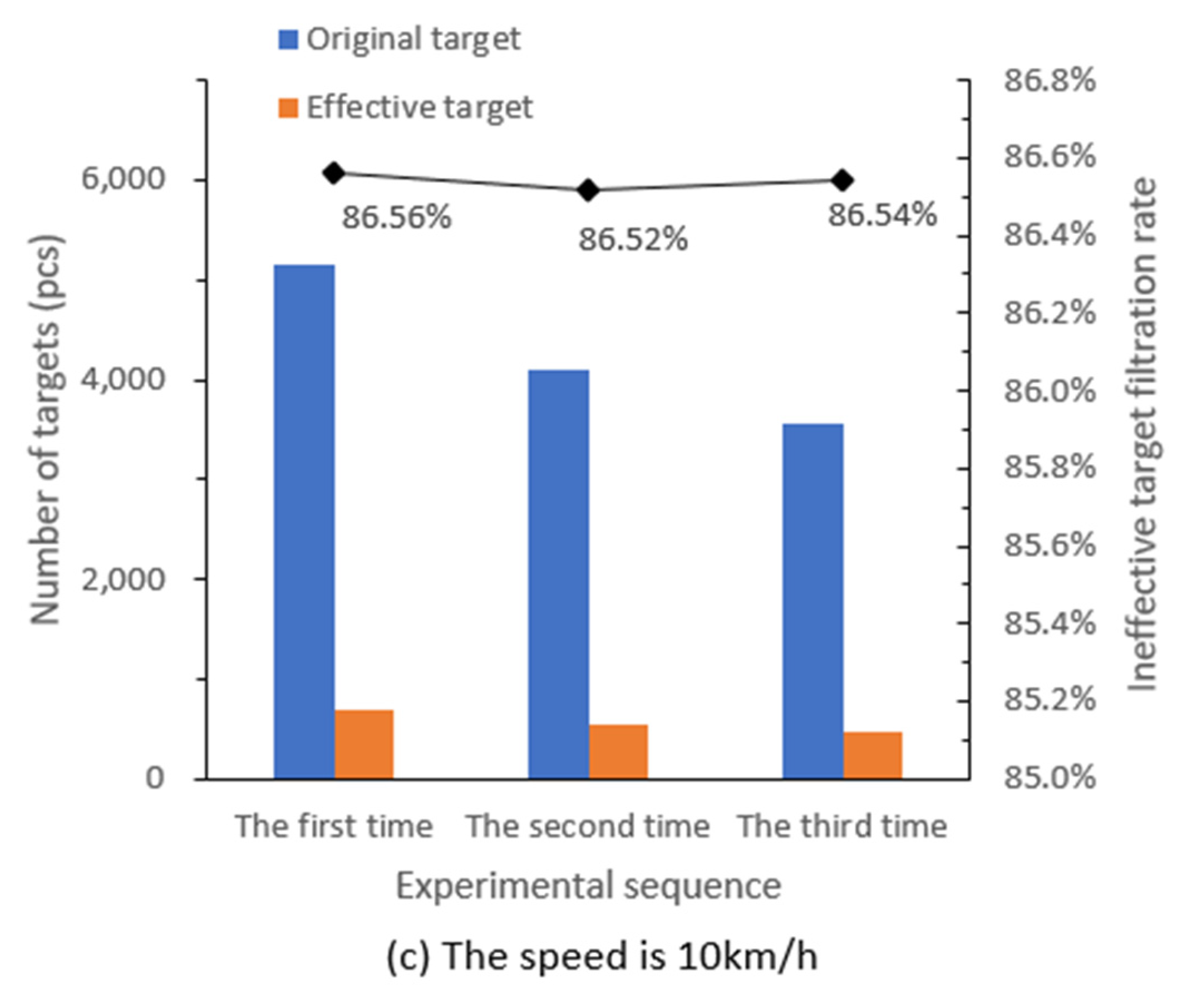
| Smooth driving 10 km/h/(%) | 86.56% | 86.52% | 86.54% | 86.54% |
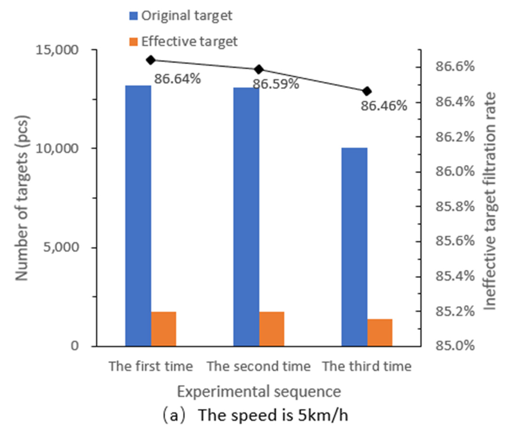
| Driving with vibration 5 km/h/(%) | 86.64% | 86.59% | 86.46% | 86.56% |
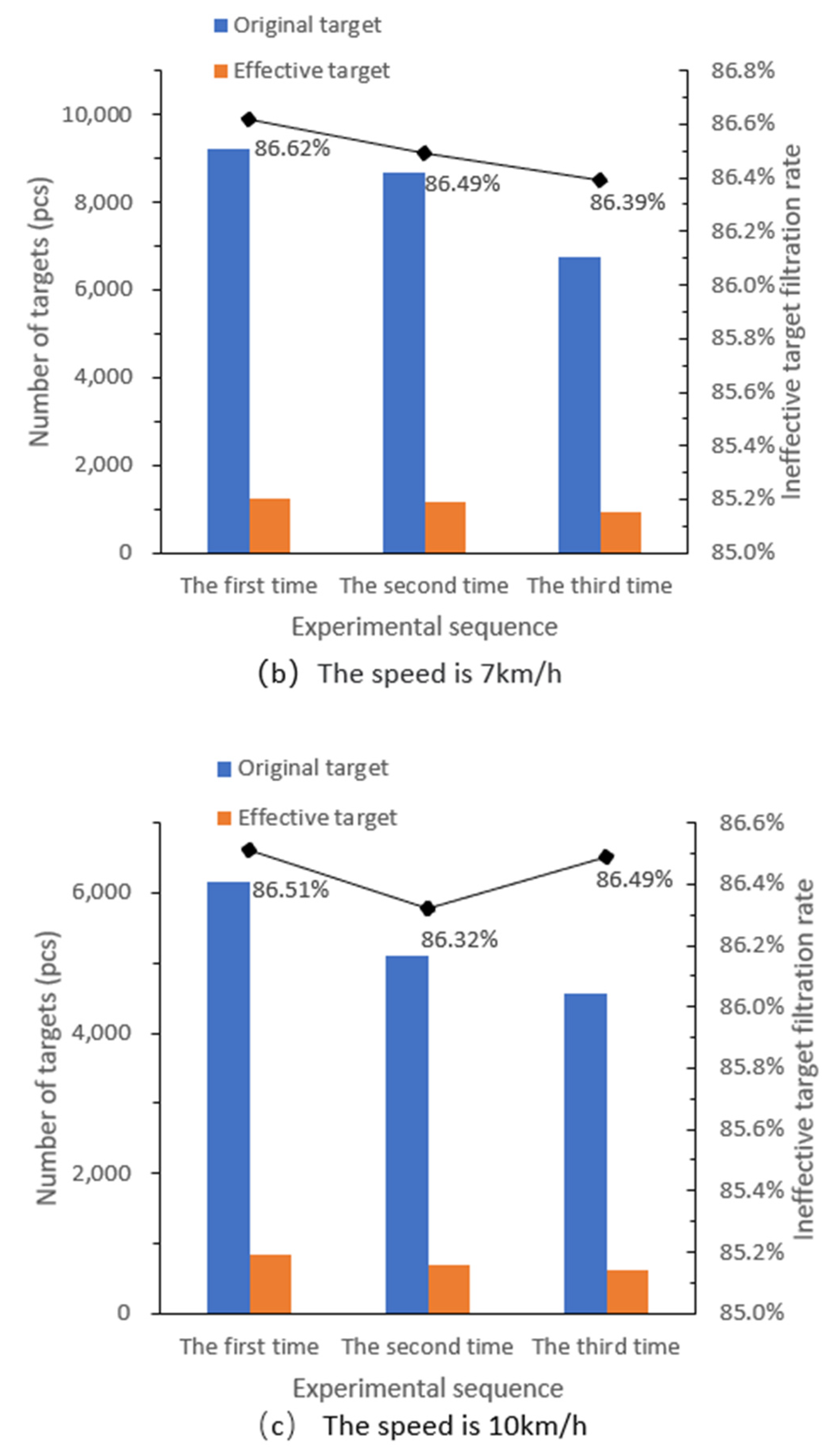
| Driving with vibration 7 km/h/(%) | 86.62% | 86.49% | 86.39% | 86.50% |
| Driving with vibration 10 km/h/(%) | 86.51% | 86.32% | 86.49% | 86.44% |
Disclaimer/Publisher’s Note: The statements, opinions and data contained in all publications are solely those of the individual author(s) and contributor(s) and not of MDPI and/or the editor(s). MDPI and/or the editor(s) disclaim responsibility for any injury to people or property resulting from any ideas, methods, instructions or products referred to in the content. |
© 2023 by the authors. Licensee MDPI, Basel, Switzerland. This article is an open access article distributed under the terms and conditions of the Creative Commons Attribution (CC BY) license (https://creativecommons.org/licenses/by/4.0/).
Share and Cite
Pan, Y.; Huo, F.; Wang, Z.; Zhai, S.; Geng, Z. A Millimeter-Wave Radar Tunnel Obstacle Detection Method Based on Invalid Target Filtering. Appl. Sci. 2023, 13, 6720. https://doi.org/10.3390/app13116720
Pan Y, Huo F, Wang Z, Zhai S, Geng Z. A Millimeter-Wave Radar Tunnel Obstacle Detection Method Based on Invalid Target Filtering. Applied Sciences. 2023; 13(11):6720. https://doi.org/10.3390/app13116720
Chicago/Turabian StylePan, Yue, Fulin Huo, Zhichong Wang, Shengyu Zhai, and Zhongcheng Geng. 2023. "A Millimeter-Wave Radar Tunnel Obstacle Detection Method Based on Invalid Target Filtering" Applied Sciences 13, no. 11: 6720. https://doi.org/10.3390/app13116720
APA StylePan, Y., Huo, F., Wang, Z., Zhai, S., & Geng, Z. (2023). A Millimeter-Wave Radar Tunnel Obstacle Detection Method Based on Invalid Target Filtering. Applied Sciences, 13(11), 6720. https://doi.org/10.3390/app13116720