Article

Betatron Radiation and Bremsstrahlung in the Interaction of Intense Laser Pulse with Solid Target

1
Center for Applied Physics and Technology, HEDPS, School of Physics, Peking University, Beijing 100871, China
2
Shenzhen Key Laboratory of Ultraintense Laser and Advanced Material Technology, Center for Advanced Material Diagnostic Technology, College of Engineering Physics, Shenzhen Technology University, Shenzhen 518118, China
3
Institute of Applied Physics and Computational Mathematics, Beijing 100094, China
*
Authors to whom correspondence should be addressed.
Appl. Sci. 2023, 13(11), 6632; https://doi.org/10.3390/app13116632
Submission received: 17 April 2023 / Revised: 24 May 2023 / Accepted: 26 May 2023 / Published: 30 May 2023
(This article belongs to the Special Issue Progress on Laser Plasma Interaction)

Abstract

:
X-ray generation via synchrotron radiation and bremsstrahlung in the interaction of short laser pulses with a solid target is of much current interest owing to its numerous applications. The efficiency of laser to X-ray energy conversion is thus a crucial factor. We found that the energy conversion efficiency of synchrotron radiation and bremsstrahlung is mainly governed by the ratio of the laser pulse width to the preplasma width, which is in turn governed by the laser profile, intensity, and spot size. Synchrotron radiation dominates when the ratio is less than unity, otherwise bremsstrahlung dominates. The type of radiation can thus be controlled by tailoring the laser parameters.

1. Introduction

Depending on their energy and other properties, high-energy X-rays from the interaction of high-intensity lasers with solid targets have a wide range of applications in the basic sciences [1], medical imaging [2,3], defense, and other industries [4,5,6], etc. In laser–plasma interaction (LPI), the properties of the low-density transparent preplasma produced by the laser prepulse can play important roles, especially in X-ray generation [1]. If the preplasma is sufficiently long, a considerable amount of laser energy will be deposited in the preplasma, producing relativistic electrons. The latter can generate X- and even γ -rays through inverse-Compton scattering [7,8] and/or betatron radiation [9], which can be regarded as synchrotron radiation, during their motion in low-density preplasma region. Knowledge of the intensity and spectral distribution of these high-energy radiations are useful for diagnosing the preplasma as well as the laser-driven relativistic electrons. Moreover, with higher ( I L 10 22 W/cm 2 ) laser intensity, radiation reactions in the above radiation processes can become important [10,11,12,13], thereby providing an experimental platform for verifying the existing assumptions/theories of radiation reaction [13]. As the laser reaches the target’s critical-density region, its energy will be absorbed by the affected electrons through collisionless mechanisms, such as vacuum and j × B heating, and accelerating them to relativistic energies [14,15,16,17,18]. As they collide with the target ions and atoms, the energetic electrons can generate bremsstrahlung as well as characteristic X-rays. High-energy X-rays can easily pass through solid matter and are thus useful as a backlighter for diagnosing the content and structure of dense matter [19,20,21,22,23,24,25,26,27]. Bremsstrahlung from laser–target interactions are also of basic scientific interest. For example, Chen et al. recently experimentally considered >70 keV X-ray conversion efficiency with the ARC laser at the National Ignition Facility [28], Compant La Fontaine et al. considered laser-driven photon dose and bremsstrahlung spectrum using various metal targets [29],and Singh et al. considered laser-driven plasma and bremsstrahlung characterization [30], etc. The laser intensities and pulse lengths in these experiments are typically less than 10 19 W/cm 2 and greater than 1 ps.
Recently, there has been much theoretical and experimental interest in the energy conversion efficiency of the radiation mechanisms [31,32,33,34,35,36,37,38,39], as well as their dependence on the laser and target parameters [40,41,42,43]. For example, Pandit et al. [40] found that if the laser intensity exceeds 10 22 W/cm 2 , synchrotron radiation dominates. Wan et al. [41] found that, for 1 μ m thick Al and Au targets, synchrotron radiation dominates if I L 10 21 W/cm 2 and I L 10 22 W/cm 2 , respectively. Vyskočil et al. [42] found that, in general, the conversion efficiency of bremsstrahlung increases with the target thickness and the laser intensity, and the conversion efficiency of nonlinear inverse Compton scattering increases with the laser intensity [43]. These studies suggest that synchrotron radiation dominates for high-laser intensities ( I L 10 22 W/cm 2 ) and/or thin targets. More recently, Miller et al. [44] simulated bremsstrahlung X-ray generation in laser–solid interactions for use as light sources in high-energy density science. A phenomenological model where the temperature scales with the laser duration and plasma density scalelength is presented for the transition from superponderomotive to ponderomotive temperatures.
However, the above studies involve bremsstrahlung driven by highly intense lasers. For interactions of moderate-intensity (say, 10 19 I 10 21 W/cm 2 ) lasers with solid targets, the dominant radiation mechanism still remains unclear. In this paper, using mainly two-dimensional particle-in-cell (PIC) simulations, we investigate and compare the conversion efficiencies of synchrotron radiation and bremsstrahlung in this regime, especially their dependence on the preplasma scalelength, laser intensity, and spot size. We found that the relationship is mainly determined by the parameter α c τ d / Δ x 1 , where c is the light speed, and τ d and Δ x 1 are the widths of the laser pulse and the transparent preplasma, respectively. The dominant radiation mechanism can therefore be controlled by tailoring laser pulse parameters, such as its contrast, intensity, and spot size.

2. Methods and Simulation Setup

2.1. Simulation Tool

The PIC code EPOCH [45] (version number 4.17.8) used in our study of the electron acceleration and radiation processes is capable of simulating the bremsstrahlung radiation while calculating the movement of electrons in the electromagnetic fields by implementing a Monte-Carlo (MC) module in the PIC loop [41,42].
In the MC module, bremsstrahlung photon generation in the interaction of laser-driven energetic electrons with the target atoms is modeled by random scattering events that depend on the differential cross section of the collision event. The reduced energy κ of the produced bremsstrahlung photon is obtained according to the probability distribution p ( ε , κ ) = 1 κ χ ( Z , ε , κ ) Θ κ κ cr , where ε is the electron energy, Z is the atomic number, κ is the ratio of the photon-to-electron energies, κ c r is the cut-off energy, and χ ( Z , ε , κ ) is a scaled differential cross section. For electrons with energy above 500 keV, the photon emission angle is set to be parallel to the electron momenta.

2.2. Simulation Setup

In the simulations, a linearly polarized (in the y direction) Gaussian laser pulse of wavelength λ = 800 nm and period T L = λ / c 2.67 fs enters the simulation box from the left boundary and propagates in the x (or longitudinal) direction. The copper solid-density plasma slab is 5.0 μ m thick and of uniform electron density n e = 30 n c , where n c = 4 π 2 ε 0 m e c 2 / e 2 λ 2 1.75 × 10 21 cm 3 is the critical density. The electron density profile of the preplasma is n e ( x ) = n e ( x 0 ) exp ( | x x 0 | / L ) , where n e ( x 0 ) = 30 n c , x < x 0 , and x 0 is the position of the slab’s front surface. The preplasma is truncated at n e = 0.05 n c .
The rectangular simulation box is 125 and 40 μ m in the x- and y-directions, respectively. The spatial resolution is 0.0125 μ m and 0.02 μ m for the x- and y-directions, respectively. In each cell there are 200 macroparticles each for the electrons and copper ions. The boundary conditions are open for the fields and thermal for the particles. When a particle leaves the simulation box boundary, it is replaced by an incoming particle sampled from a Maxwellian distribution with the same temperature [45,46]. Both synchrotron radiation and bremsstrahlung photons are recorded at their emission location, but low-energy (<10 keV) photons are ignored. Unless otherwise stated, the total simulation time is t end 200 T L .
For investigating the effect of the preplasma scale length L, the laser parameters are fixed at focal spot radius r 0 = 3.0 μ m, FWHM temporal duration τ d = 9 T L , peak intensity I 0 = 7 × 10 20 W/cm 2 (i.e., the laser parameter is a 0 18 ), with L = 0.15 , 0.5 , 1.5 , 3.0 , 5.0 , and 15.0 μ m considered. For investigating the effects of the laser parameters, we consider two control groups. First, the effect of the laser intensity is studied for focal spot radius r 0 = 3.0 μ m. For L = 0.5 μ m, we set a 0 = 6.0 , 9.0 , 18.0 , and 38.0 ; and for L = 5.0 μ m we set a 0 = 6.0 and 18.0 . In addition, three 1D simulations for L = 0.5 μ m and a 0 = 6.0 , 18.0 , and 38.0 are carried out in order to see the longtime ( t end 5.0 ps) behavior of bremsstrahlung. In the second control group, the effect of the laser focal spot radius r 0 is studied for a 0 = 18.0 . For L = 0.5 μ m, we set r 0 = 0.5 , 1.0 , 1.5 , 2.0 , 2.5 , 3.0 , 4.5 , 6.0 , 7.5 , and 9.0 μ m; and for L = 5.0 μ m we set r 0 = 0.5 , 1.0 , and 3.0 μ m. The laser pulse energy is the same in all our simulations.

3. Results

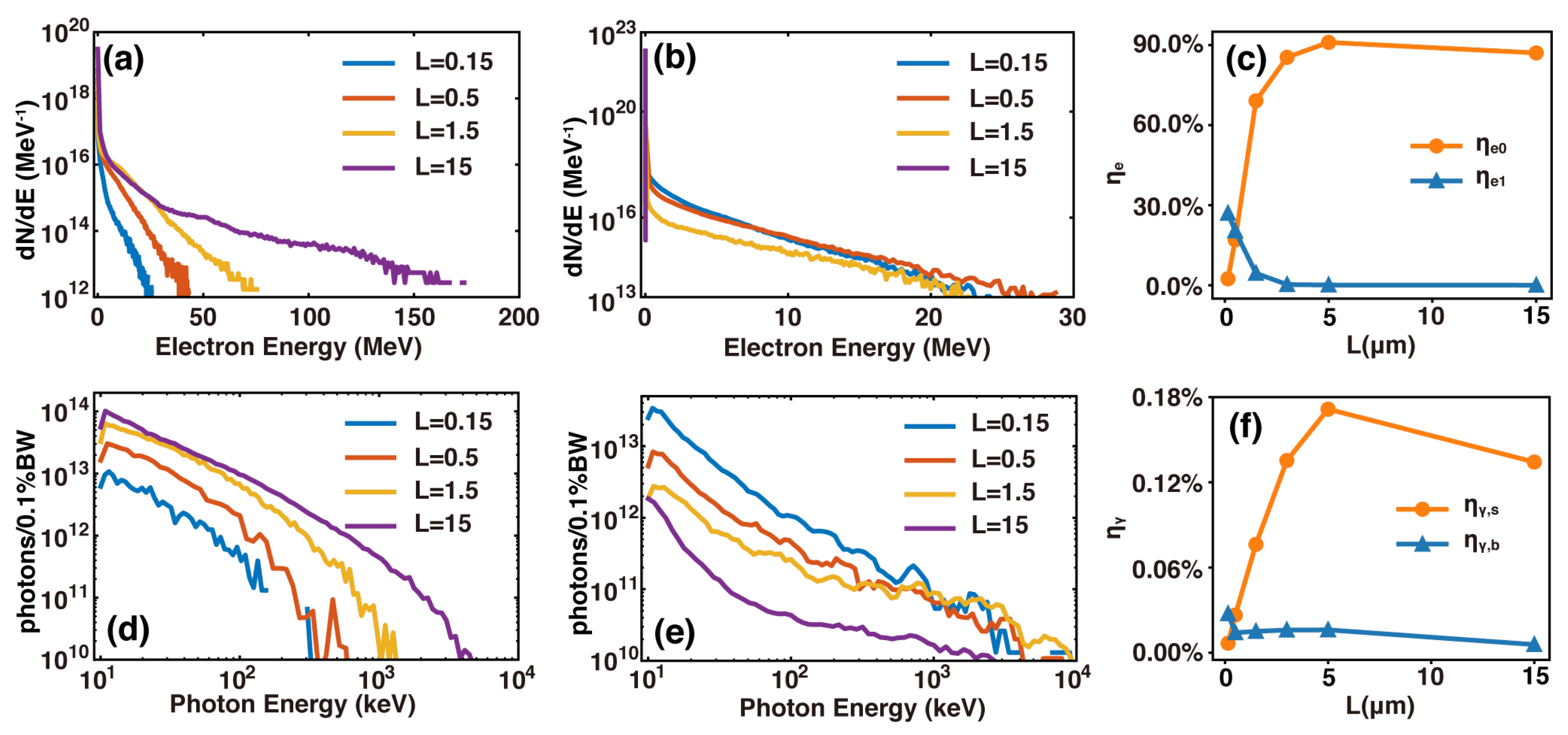
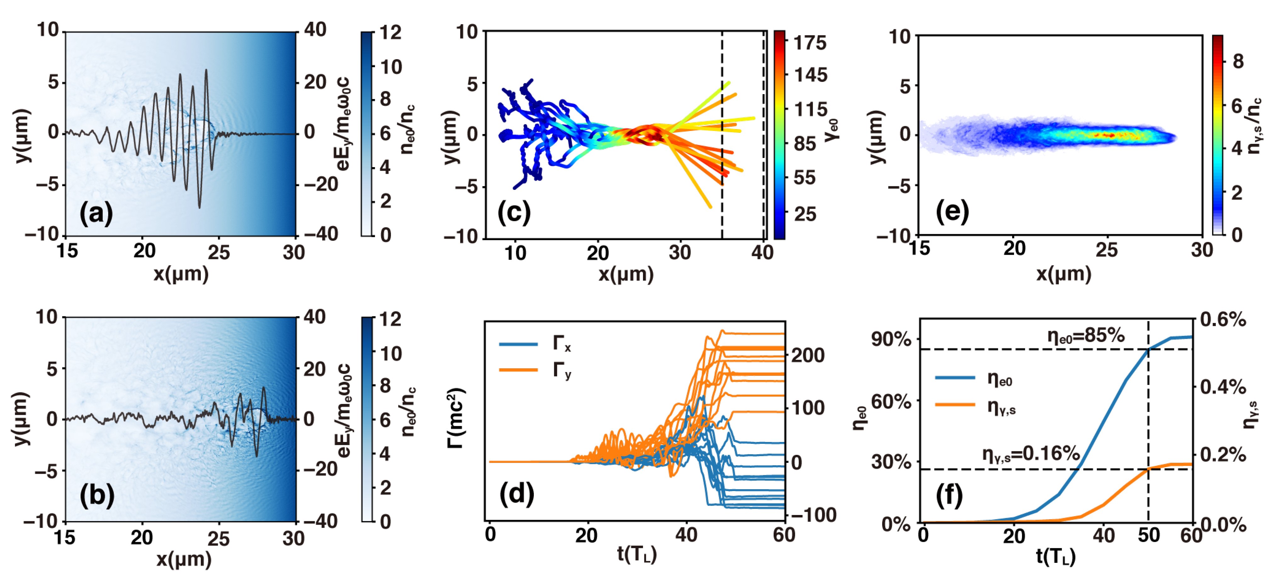
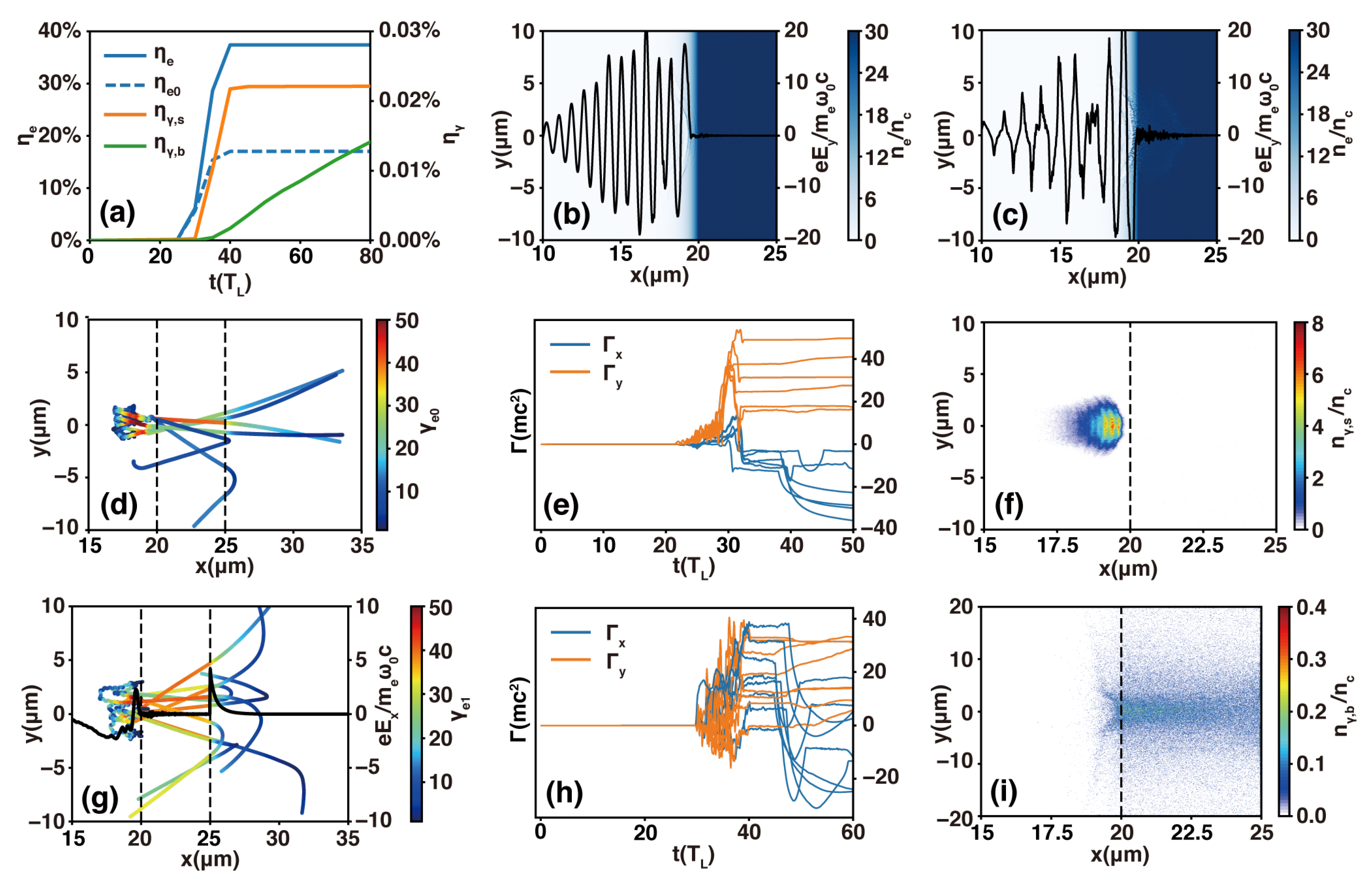
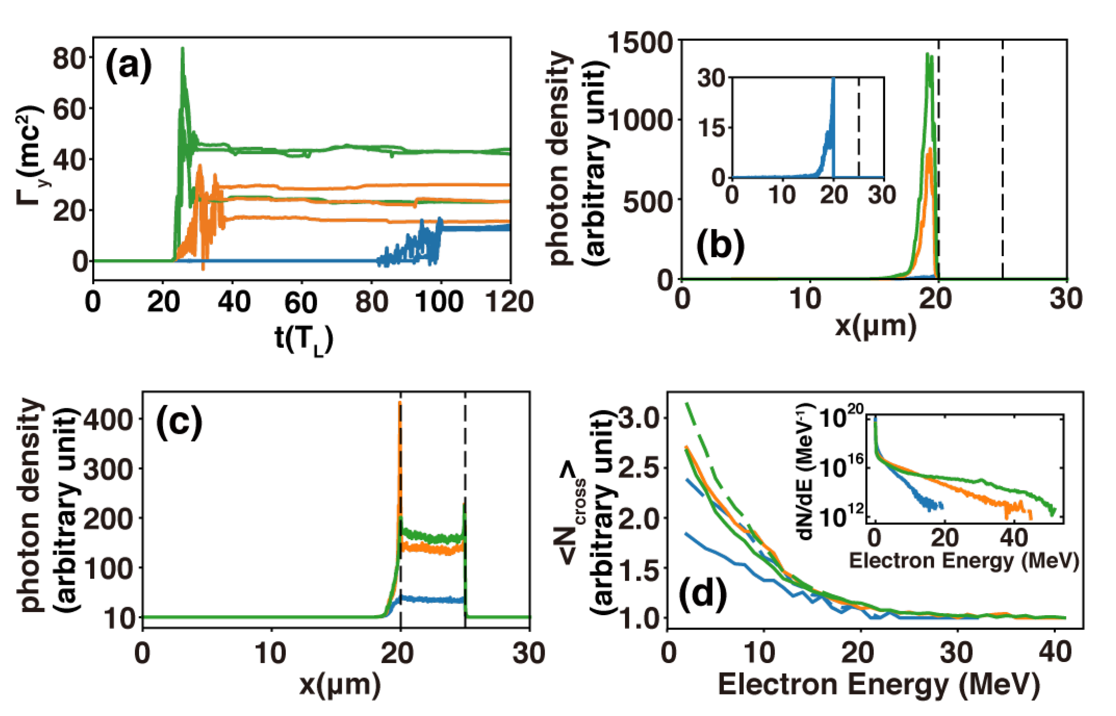
3.1. Effect of the Preplasma Scalelength

From Figure 1c,f, we see that the preplasma scalelength L affects the laser energy transfer to the electrons and thus the radiation. For 3.0 μ m < L < 15.0 μ m, the energy conversion rate η e 0 from the laser to preplasma electrons is high, but that ( η e 1 ) from the laser to slab electrons is very low. For 0.15 μ m < L < 3.0 μ m, η e 0 decreases rapidly with L, but η e 1 increases. Despite the differences in detail, the dependence (on the interaction parameters) of the energy conversion rate ( η γ , s ) from the laser to synchrotron radiation is similar to that of η e 0 . That is, synchrotron radiation is mainly produced by the laser-driven preplasma electrons, and the laser-to-bremsstrahlung energy conversion rate η γ , b is not sensitive to L for 0.5 μ m < L < 5.0 μ m. For the extreme case L = 15.0 μ m, bremsstrahlung photons are produced by the laser-accelerated preplasma electrons as they propagate through the slab, because no laser energy is transferred to the slab electrons with the initial solid-slab electron spectrum hardly changed, as showed by Figure 1b. Figure 1e shows that for L = 1.5 μ m the bremsstrahlung photon number is much larger than that for L = 15.0 μ m. Moreover, one can see that the slab-electron spectrum for L = 1.5 μ m is much wider, suggesting that deposition of the laser energy in the slab electrons tends to enhance η γ , b . This is because in this case more relativistic electrons are produced which give rise to bremsstrahlung as they pass through the solid slab.
For a 0 1 , the LPI contains two stages: for 0.05 n c < n e < a 0 n c , the laser can propagate in the preplasma and many of the affected electrons are accelerated by the laser fields to relativistic energies and emit high-energy photons. In the second stage, for n e > a 0 n c , the laser is cut off around n e a 0 n c and reflected. Electrons in the cut-off region (skin layer) can also be accelerated and emit high-energy photons as they interact with the laser light. Simulation results show that for given laser parameters, the laser energy deposition in the first and second stages are different as L changes. For long preplasmas with L = 15.0 , 5.0 , and 3.0 μ m, almost all the laser energy is deposited in the preplasma, and the second stage of the interaction is negligible.
As an example of the mechanisms and relative importance of synchrotron radiation and bremsstrahlung in the different parameter regimes, it may be instructive to consider the case L = 5.0 μ m in more detail. With the slab located in 35 μ m < x < 40 μ m, a long preplasma of density 0.05 n c < n e < a 0 n c is located in 3.0 μ m < x < 32.4 μ m. As the laser pulse propagates through the preplasma, its ponderomotive force displaces the background electrons, forming a positive channel with bounding sheaths of elevated density, as can be seen in Figure 2a. Figure 2c shows that these electrons are readily accelerated to relativistic energies by the laser light, and they can continuously gain energy by direct laser acceleration (DLA) as they co-propagate with the laser, as well as emit high-energy photons, as shown in Figure 2d,e. Figure 2b shows that at around t = 50 T L , the laser is cut off near x = 28 μ m, but the co-moving relativistic electrons continue to move forward. Figure 2f shows that at about t = 50 T L , η e 0 0.85 and η γ , s 0.0016 . That is, most of the laser energy is converted into that of preplasma electrons, and with only a small amount into that of the synchrotron photons. Both η e 0 and η γ , s become saturated shortly after the laser propagation is cut off. That is, the photons here are from synchrotron (more precisely, betatron) radiation rather than inverse-Compton scattering. In this case, the synchrtron radiation dominates since η γ , s η γ , b .
For medium-length preplasmas with L = 1.5 μ m and 0.5 μ m, the laser energy is deposited in both the first and second stages of the LPI. As an example, we consider the case L = 0.5 μ m in more detail. The slab is located in 20 μ m < x < 25 μ m, the preplasma region with density 0.05 n c < n e < a 0 n c is located in 16.8 μ m < x < 19.74 μ m. As shown in Figure 3a, from the beginning of the LPI to t 35 T L , η e 0 remains roughly the same as η e ( η e 0 + η e 1 = η e ). However, η e continues to increase even though η e 0 is saturated at t 35 T L , and becomes saturated only at t 40 T L . That is, before t 35 T L , the LPI is in the first-stage, and from t 35 T L to t 40 T L , the LPI is in the second-stage. Similar to the long preplasma case, during the first-stage, the laser pulse propagates in preplasma, as shown in Figure 3b. Figure 3d,e show that a small number of electrons can be accelerated to relativistic energies by DLA. Figure 3f shows that these electrons can emit high-energy photons by betatron radiation. However, the orange curve in Figure 3a shows that η γ , s 0.02 % , much less than that in long preplasma case. During the second-stage interaction, the laser pulse propagation is cut off at dense plasma boundary with the laser pulse being reflected, as shown in Figure 3c. However, the laser electric field can still penetrate into the skin layer of the dense plasma and accelerate the surface electrons there to relativistic energies. The black curve in Figure 3g shows that with the expulsion of these energetic electrons, an electrostatic sheath field is built up. Figure 3g,h show that electrons on the front surface are then accelerated by both the laser electric field and the sheath field until the end of the second-stage interaction. Relativistic electrons accelerated in both the first and second stages can emit high-energy photons by bremsstrahlung, as can be seen in Figure 3i. After the laser pulse is fully reflected at t 40 T L , η γ , s tends to saturate, but η γ , b continues to increase, as shown in Figure 3a, due to bouncing of the energetic electrons trapped between the electrostatic sheath fields at the front and back slab surfaces. Eventual saturation of bremsstrahlung shall be discussed later.
For the short preplasma with L = 0.15 μ m, the slab is located in 5.0 μ m < x < 10.0 μ m, with the region 0.05 n c < n e < a 0 n c in 4.04 μ m < x < 4.92 μ m. After only about one cycle in the preplasma, the laser pulse begins to interact with the slab. There is almost no laser energy loss in the preplasma, so that the first interaction stage is ignorable. However, the laser is reflected after penetrating only about a skin depth into the slab, as shown in Figure 4a. Nevertheless, the laser fields can accelerate the surface electrons to 10 MeV in just one cycle ( 6 T L < t < 6 T L + 2 τ d ), corresponding to the rapid-rising stage of η e 1 shown in Figure 4d. Interaction between the laser pulse with the slab ends at around t = 24 T L , when η e 1 becomes saturated at about 27 % . However, the electrons trapped between the sheath fields at the slab’s surfaces can emit high-energy bremsstrahlung photons as they bounce back and forth, as can be seen in Figure 4b,c. Thus, bremsstrahlung lasts much longer than the laser pulse duration, as can be seen from the evolution of η γ , b shown in Figure 4d. As mentioned, the low level (<0.01%) of η γ , s is because no laser energy is deposited in the first-stage interaction (i.e., with the preplasma).

3.2. Effect of Laser Intensity and Spot Size

For fixed laser parameters, the parameter α changes from ≪1 to ≫1 as the preplasma width is reduced. We found that with increasing α , synchrotron radiation is suppressed and bremsstrahlung becomes dominant. A similar behavior also appears if the preplasma scalelength is fixed but the laser pulse parameter is varied. The change in laser pulse duration τ d can directly change α . For a laser pulse of fixed energy, we have τ d a 0 2 r 0 2 = constant. In the 2D cases considered, this relation becomes τ d a 0 2 r 0 = constant. Thus, the parameter α , or the radiation mechanism, can be controlled by tailoring a 0 and/or r 0 .
For long preplasmas (say L = 5.0 μ m), synchrotron radiation is dominant since η γ , s η γ , b . In this case, α 1 for a 0 = 18 , r 0 = 3.0 μ m, and τ d = 9 T L . Synchrotron radiation suppression can thus be achieved by increasing α , such as by keeping a 0 unchanged and decreasing r 0 , or keeping r 0 unchanged and decreasing a 0 , as shown in Figure 5a. Relative to the original case (orange curve with triangle marks), η γ , s decreases with decreasing r 0 ( r 0 = 1.0 μ m, orange curve with squares) and decreasing a 0 ( a 0 = 6 , orange curve with circles), but η e for these three cases (blue curves) are not so different. In fact, for all the three cases, η e 0 η e (the blue dashed and solid curves in Figure 5a overlap). This indicates that in all the three cases almost all of the laser energy is transferred to the preplasma electrons. If a 0 or r 0 is decreased, η γ , s can be reduced to a level comparable with η γ , b , as shown in Figure 5b. In fact, for r 0 = 1.0 μ m, we have η γ , s 0.03 % (orange and green curves with squares). For a 0 = 6 , (orange and green curves with circles), we see that η γ , s < 0.01 % , and η γ , b overtakes η γ , s . It is of interest to note that although the laser pulse parameters are quite different in these three cases, the bremsstrahlung power from them are not much different, namely d η γ , b / d t = 1.53 × 10 6 fs 1 for a 0 = 18 , r 0 = 3.0 μ m, d η γ , b / d t = 1.43 × 10 6 fs 1 for a 0 = 18 , r 0 = 1.0 μ m, and d η γ , b / d t = 1.03 × 10 6 fs 1 for a 0 = 6 , r 0 = 3.0 μ m.
For the medium-width preplasma, such as L = 0.5 μ m, we have η γ , s 0.02 % , and η γ , b with a steady growth rate of 5.40 × 10 6 fs 1 overtakes η γ , s , as shown in Figure 5d by the orange and green curves with circles. In this case, α > 1 for a 0 = 18 , r 0 = 3.0 μ m, and τ d = 9 T L . Keeping r 0 unchanged, the variation of η γ , s with a 0 is shown in Figure 5c. Increasing a 0 from 18 to 38 causes α to change from > 1 to < 1 , with η γ , s reaching a high level of 0.1 % (orange curve with squares). Decreasing a 0 from a 0 = 18 to a 0 = 6 causes α to change from > 1 to 1 , with η γ , s becoming negligible (orange curve with triangles). As a 0 decreases, η e 0 / η e also decreases, as shown by the blue curves in Figure 5c. Similar to that for L = 5.0 μ m, although the laser parameters are different, the bremsstrahlung radiation power are not very different, namely, d η γ , b / d t = 5.40 × 10 6 fs 1 for a 0 = 18 , d η γ , b / d t = 4.76 × 10 6 fs 1 for a 0 = 38 , and d η γ , b / d t = 5.01 × 10 6 fs 1 for a 0 = 6 as shown in the panel (d). It is convenient to measure the long-time behavior of bremsstrahlung by the attenuation of d η γ , b / d t to exp ( 1 ) of its peak value. To save computation time we carried out 1D simulations for this purpose. It should however be noted that this may overestimate η γ , b and the bremsstrahlung duration since lateral escape of electrons and light is precluded. The results are shown in Figure 5e. For example, for a 0 = 18 (orange curve), the peak value of d η γ , b / d t 5.00 × 10 6 fs 1 . Around t = 1085 T L , it decreases to ∼1.83 × 10 6 fs 1 , or exp ( 1 ) of the peak value, and the corresponding η γ , b is ∼0.17%. Note that the bremsstrahlung pulse lasts ∼1000 T L , much longer than that ( τ d = 9 T L ) of the driving laser pulse. The results for a 0 = 6 and 38 are similar, with the long-time behavior of η γ , b reaching 0.1∼0.2%, respectively, and the bremsstrahlung duration lasting much longer than the laser pulse.
With the preplasma scalelength L fixed, η γ , s depends mainly on α and the electron energy. Electron energy gain by DLA during the first-stage of interaction depends strongly on a 0 , as can be seen in Figure 6a. These high-energy electrons emit photons by synchrotron radiation during the first-stage of the interaction, as shown in Figure 6b. The photon density (green curve) for a 0 = 38 is appreciably larger than that (orange curve) for a 0 = 18 due to the higher electron energy, the photon density (blue curve in the inset) for a 0 = 6 is almost negligible. This is consistent with the η γ , s levels of these three cases. Figure 6c shows the longitudinal distribution of bremsstrahlung photons of these three cases up to 160 T L . Bremsstrahlung photons arise mainly from the slab region. Different from synchrotron radiation, where radiation power depends strongly on the electron energy, radiation power of bremsstrahlung is independent of electron energy. Thus, the bremsstrahlung photon densities a 0 = 38 and 18 are not much different, but their electron energy spectra are clearly different in high-energy regions (>20 MeV), as shown in Figure 6c and the inset in Figure 6d. The reason why the photon density of a 0 = 6 case (the blue curve in Figure 6c) is at a relatively low level is that the bremsstrahlung pulse is delayed, as can be seen in Figure 5d. The conversion efficiency η γ , b depends on the number of times the relativistic electrons traverse the slab, which depends mainly on relativistic electrons with lower energy, since they are more numerous and more easily trapped by the electrostatic sheath fields. Figure 6d shows the average number N cross of times that electrons of different energies traverse the slab up to t = 160 T L . For the >20 MeV electrons, N cross 1 , since such high-energy electrons can propagate through the slab without being trapped. For the <20 MeV electrons, N cross increases with decreases in electron energy, indicating that electrons of lower energies can be trapped in the slab and can traverse it many times. Up to t = 160 T L , N c r o s s for a 0 = 38 (solid green curve) and a 0 = 18 (solid orange curve), and thus η γ , b , are not much different. The N cross for a 0 = 6 case (solid blue line) is small because rising of the laser pulse is relatively slow with τ d = 81 T L . At t = 200 T L , the difference of N cross between a 0 = 6 and 38 becomes smaller, as can be seen from the dashed curves in Figure 6d. This is consistent with the result that η γ , b for these three cases are similar.
Decreasing r 0 also decreases the electron energy gained by the DLA, so that η γ , s remains at a relatively low level and there is no large variation in η γ , b , as can be seen in Figure 5a,b. This behavior can be attributed to the fact that divergence of the laser pulse increases with a decrease of its focal spot, so that the laser electric field decays rapidly as it propagates in the preplasma. The dispersion angle of the Gaussian laser pulse is θ λ / π r 0 , with r 0 the focal spot radius at the beam waist. The laser electric field decreases with the propagation distance d, or
a 0 a w = 1 1 + d λ π r 0 2 2 ,
with a w being the value of a 0 at the beam waist. If the beam waist is at the preplasma boundary ( n e = 0.05 n c ) and d = L / 2 Δ x 1 , for preplasma with L = 5.0 μ m and r 0 = 3.0 , 1.0 , 0.5 μ m, we get a 0 / a w = 0.996 , 0.844 , 0.366 , respectively, showing that the laser field attenuation is due to tight focusing. For preplasma with L = 0.5 μ m and r 0 = 3.0 , 1.0 , 0.5 μ m, we get a 0 / a w = 1.00 , 0.998 , 0.969 , respectively, indicating that for short preplasmas, suppression of η γ , s is not obvious, which was also verified by simulations (not shown).

4. Discussion

We have shown by simulating with different parameter combinations that synchrotron radiation dominates when α < 1 and bremsstrahlung dominates if α > 1 . The dependence of α on the major parameters a 0 and L may be obtained by noting the interdependence of the laser and preplasma parameters. For a laser with a fixed energy and focal spot, we obtain α 1 / a 0 2 L , where we have noted that I L a 0 2 . Figure 7a shows a map of α ( a 0 , L ) . One can see that for fixed L ( a 0 ), reducing a 0 (L) can change the dominant radiation mechanism from synchrotron radiation to bremsstrahlung. On the other hand, for laser pulse with fixed energy and intensity, we obtain α ( r 0 L ) 1 1 + c λ L / 2 π r 0 2 2 , as shown in Figure 7b. Thus, for fixed L ( r 0 ), reducing r 0 (L) can change the dominant radiation mechanism from synchrotron radiation to bremsstrahlung. In Figure 7, the cases simulated in the preceding sections are marked by stars.
In summary, we employ the PIC simulation code EPOCH including a Monte-Carlo implementation for bremsstrahlung to investigate electron acceleration and the subsequent synchrotron radiation and bremsstrahlung processes in the interaction of intense laser pulses with solid-density targets. The energy-conversion efficiencies of synchrotron radiation and bremsstrahlung are investigated in the moderate laser intensity range 10 19 I 10 21 W/cm 2 as a function of the laser and plasma parameters. It is found that the laser pulse and the transparent preplasma widths are important parameters determining the two radiation processes, and that the dominant radiation mechanism can be controlled by tailoring the parameter α = c τ d / Δ x 1 , or the laser contrast, intensity, and spot size. Our findings can thus assist in controlling the radiation type in LPI research and applications.

Author Contributions

Conceptualization, simulation, data analysis and writing—original draft preparation, L.L. and R.L.; writing—review and editing, L.L., R.L., M.Y. and T.H.; methodology and software, H.Z.; validation and supervision, L.J., K.J., S.W. and B.Q.; project administration, C.Z. and X.H. All authors have read and agreed to the published version of the manuscript.

Funding

This research was funded by the National Natural Science Foundation of China (Grants No. 11875092, No. 12175154, No. 12005149, and No. 12205201), the Natural Science Foundation of Top Talent of SZTU (Grant No. 2019020801001), and the Shenzhen Science and Technology Program (Grant No. RCYX20221008092851073).

Institutional Review Board Statement

Not applicable.

Informed Consent Statement

Not applicable.

Data Availability Statement

The data that support the findings of this study are available from the corresponding author upon reasonable request.

Acknowledgments

The epoch code is used under UK EPSRC contract (EP/G055165/1 and EP/G056803/1).

Conflicts of Interest

The authors declare no conflict of interest.

Abbreviations

The following abbreviations are used in this manuscript:
LPILaser–plasma interaction
PICParticle-in-cell
MCMonte-Carlo
FWHMFull Width at Half Maximum
DLADirect laser acceleration
1Done-dimension
2Dtwo-dimension
fsfemto second

References

  1. Gibbon, P. Short Pulse Laser Interactions with Matter: An Introduction; World Scientific: London, UK, 2005. [Google Scholar]
  2. Herrlin, K.; Svahn, G.; Olsson, C.; Pettersson, H.; Tillman, C.; Persson, A.; Wahlström, C.; Svanberg, S. Generation of x rays for medical imaging by high-power lasers: Preliminary results. Radiology 1993, 189, 65–68. [Google Scholar] [CrossRef] [PubMed]
  3. Kieffer, J.; Krol, A.; Jiang, Z.; Chamberlain, C.; Scalzetti, E.; Ichalalene, Z. Future of laser-based X-ray sources for medical imaging. Appl. Phys. B 2002, 74, s75–s81. [Google Scholar] [CrossRef]
  4. Rusby, D.; Brenner, C.; Armstrong, C.; Wilson, L.; Clarke, R.; Alejo, A.; Ahmed, H.; Butler, N.M.H.; Haddock, D.; Higginson, A.; et al. Pulsed X-ray imaging of high-density objects using a ten picosecond high-intensity laser driver. In Proceedings of the Emerging Imaging and Sensing Technologies, Edinburgh, UK, 26–29 September 2016. [Google Scholar]
  5. Jones, C.P.; Brenner, C.M.; Stitt, C.A.; Armstrong, C.; Rusby, D.R.; Mirfayzi, S.R.; Wilson, L.A.; Alejo, A.; Ahmed, H.; Allott, R.; et al. Evaluating laser-driven Bremsstrahlung radiation sources for imaging and analysis of nuclear waste packages. J. Hazard. Mater. 2016, 318, 694–701. [Google Scholar] [CrossRef] [Green Version]
  6. Brenner, C.; Mirfayzi, S.; Rusby, D.; Armstrong, C.; Alejo, A.; Wilson, L.; Clarke, R.; Ahmed, H.; Butler, N.; Haddock, D.; et al. Laser-driven X-ray and neutron source development for industrial applications of plasma accelerators. Plasma Phys. Control. Fusion 2015, 58, 014039. [Google Scholar] [CrossRef] [Green Version]
  7. Martinez, B.; d’Humières, E.; Gremillet, L. Synchrotron radiation from ultrahigh-intensity laser-plasma interactions and competition with Bremsstrahlung in thin foil targets. Phys. Rev. Res. 2020, 2, 043341. [Google Scholar] [CrossRef]
  8. Zhang, C.; Zhu, Y.; Lv, J.; Xie, B. Simulation Study of a Bright Attosecond γ-ray Source Generation by Irradiating an Intense Laser on a Cone Target. Appl. Sci. 2022, 12, 4361. [Google Scholar] [CrossRef]
  9. Rousse, A.; Phuoc, K.; Shah, R.; Pukhov, A.; Lefebvre, E.; Malka, V.; Kiselev, S.; Burgy, F.; Rousseau, J.; Hulin, D.; et al. Production of a keV X-ray beam from synchrotron radiation in relativistic laser-plasma interaction. Phys. Rev. Lett. 2004, 93, 135005. [Google Scholar] [CrossRef] [Green Version]
  10. Blackburn, T. Radiation reaction in electron–beam interactions with high-intensity lasers. Rev. Mod. Plasma Phys. 2020, 4, 5. [Google Scholar] [CrossRef] [Green Version]
  11. Michel, P.; Schroeder, C.; Shadwick, B.; Esarey, E.; Leemans, W. Radiative damping and electron beam dynamics in plasma-based accelerators. Phys. Rev. E 2006, 74, 026501. [Google Scholar] [CrossRef]
  12. Zeng, M.; Seto, K. Radiation reaction of betatron oscillation in plasma wakefield accelerators. New J. Phys. 2021, 23, 075008. [Google Scholar] [CrossRef]
  13. Gonoskov, A.; Blackburn, T.G.; Marklund, M. Charged particle motion and radiation in strong electromagnetic fields. Rev. Mod. Phys. 2022, 94, 045001. [Google Scholar] [CrossRef]
  14. Freidberg, J.; Mitchell, R.; Morse, R.; Rudsinski, L. Resonant absorption of laser light by plasma targets. Phys. Rev. Lett. 1972, 28, 795. [Google Scholar] [CrossRef] [Green Version]
  15. Malka, G.; Miquel, J. Experimental confirmation of ponderomotive-force electrons produced by an ultrarelativistic laser pulse on a solid target. Phys. Rev. Lett. 1996, 77, 75. [Google Scholar] [CrossRef]
  16. Wilks, S.; Kruer, W.; Tabak, M.; Langdon, A. Absorption of ultra-intense laser pulses. Phys. Rev. Lett. 1992, 69, 1383. [Google Scholar] [CrossRef] [PubMed]
  17. Pukhov, A.; Meyer-ter-Vehn, J. Relativistic laser-plasma interaction by multi-dimensional particle-in-cell simulations. Phys. Plasmas 1998, 5, 1880–1886. [Google Scholar] [CrossRef]
  18. Brunel, F. Not-so-resonant, resonant absorption. Phys. Rev. Lett. 1987, 59, 52. [Google Scholar] [CrossRef]
  19. Koch, J.; Aglitskiy, Y.; Brown, C.; Cowan, T.; Freeman, R.; Hatchett, S.; Holland, G.; Key, M.; MacKinnon, A.; Seely, J.; et al. 4.5-and 8-keV emission and absorption X-ray imaging using spherically bent quartz 203 and 211 crystals. Rev. Sci. Instruments 2003, 74, 2130–2135. [Google Scholar] [CrossRef]
  20. King, J.A.; Akli, K.; Snavely, R.A.; Zhang, B.; Key, M.H.; Chen, C.D.; Chen, M.; Hatchett, S.P.; Koch, J.A.; MacKinnon, A.J.; et al. Characterization of a picosecond laser generated 4.5 keV Ti K-alpha source for pulsed radiography. Rev. Sci. Instruments 2005, 76, 076102. [Google Scholar] [CrossRef] [Green Version]
  21. Theobald, W.; Solodov, A.; Stoeckl, C.; Anderson, K.; Beg, F.; Epstein, R.; Fiksel, G.; Giraldez, E.M.; Glebov, V.Y.; Habara, H.; et al. Time-resolved compression of a capsule with a cone to high density for fast-ignition laser fusion. Nat. Commun. 2014, 5, 5785. [Google Scholar] [CrossRef] [Green Version]
  22. Sawada, H.; Fujioka, S.; Hosoda, T.; Zhang, Z.; Arikawa, Y.; Nagatomo, H.; Nishimura, H.; Sunahara, A.; Theobald, W.; Patel, P.K.; et al. Development of 4.5 keV monochromatic X-ray radiography using the high-energy, picosecond LFEX laser. J. Phys. Conf. Ser. 2016, 717, 012112. [Google Scholar] [CrossRef] [Green Version]
  23. Tommasini, R.; Hatchett, S.; Hey, D.; Iglesias, C.; Izumi, N.; Koch, J.; Landen, O.; MacKinnon, A.; Sorce, C.; Delettrez, J.; et al. Development of Compton radiography of inertial confinement fusion implosions. Phys. Plasmas 2011, 18, 056309. [Google Scholar] [CrossRef]
  24. Tommasini, R.; Bailey, C.; Bradley, D.; Bowers, M.; Chen, H.; Di Nicola, J.; Di Nicola, P.; Gururangan, G.; Hall, G.; Hardy, C.; et al. Short pulse, high resolution, backlighters for point projection high-energy radiography at the National Ignition Facility. Phys. Plasmas 2017, 24, 053104. [Google Scholar] [CrossRef] [Green Version]
  25. Sawada, H.; Daykin, T.; Hutchinson, T.; Bauer, B.; Ivanov, V.; Beg, F.; Chen, H.; Williams, G.; McLean, H. Development of broadband X-ray radiography for diagnosing magnetically driven cylindrically compressed matter. Phys. Plasmas 2019, 26, 083104. [Google Scholar] [CrossRef]
  26. Armstrong, C.D.; Brenner, C.M.; Jones, C.; Rusby, D.R.; Davidson, Z.E.; Zhang, Y.; Wragg, J.; Richards, S.; Spindloe, C.; Oliveira, P.; et al. Bremsstrahlung emission from high power laser interactions with constrained targets for industrial radiography. High Power Laser Sci. Eng. 2019, 7, e24. [Google Scholar] [CrossRef] [Green Version]
  27. Skoulakis, A.; Kaselouris, E.; Kavroulakis, A.; Karvounis, C.; Fitilis, I.; Chatzakis, J.; Fitilis, I.; Chatzakis, J.; Dimitriou, V.; Papadogiannis, N.; et al. Characterization of an X-ray source generated by a portable low-current x-pinch. Appl. Sci. 2021, 11, 11173. [Google Scholar] [CrossRef]
  28. Chen, H.; Hermann, M.R.; Kalantar, D.H.; Martinez, D.A.; Di Nicola, P.; Tommasini, R.; Landen, O.L.; Alessi, D.; Bowers, M.; Browning, D.; et al. High energy (>70 keV) X-ray conversion efficiency measurement on the ARC laser at the National Ignition Facility. Phys. Plasmas 2017, 24, 033112. [Google Scholar] [CrossRef]
  29. Compant La Fontaine, A.; Courtois, C.; Gobet, F.; Hannachi, F.; Marquès, J.R.; Tarisien, M.; Versteegen, M.; Bonnet, T. Bremsstrahlung spectrum and photon dose from short-pulse high-intensity laser interaction on various metal targets. Phys. Plasmas 2019, 26, 113109. [Google Scholar] [CrossRef]
  30. Singh, S.; Armstrong, C.D.; Kang, N.; Ren, L.; Liu, H.; Hua, N.; Rusby D., R.; Klimo, O.; Versaci, R.; Zhang, Y.; et al. Bremsstrahlung emission and plasma characterization driven by moderately relativistic laser-plasma interactions. Plasma Phys. Control. Fusion 2021, 63, 035004. [Google Scholar] [CrossRef]
  31. Huang, T.; Kim, C.; Zhou, C.; Cho, M.; Nakajima, K.; Ryu, C.; Ruan, S.; Nam, C. Highly efficient laser-driven Compton gamma-ray source. New J. Phys. 2019, 21, 013008. [Google Scholar] [CrossRef]
  32. Powers, N.; Ghebregziabher, I.; Golovin, G.; Liu, C.; Chen, S.; Banerjee, S.; Zhang, J.; Umstadter, D. Quasi-monoenergetic and tunable X-rays from a laser-driven Compton light source. Nat. Photonics 2014, 8, 28–31. [Google Scholar] [CrossRef]
  33. Huang, T.; Robinson, A.; Zhou, C.; Qiao, B.; Liu, B.; Ruan, S.; He, X.; Norreys, P. Characteristics of betatron radiation from direct-laser-accelerated electrons. Phys. Rev. E 2016, 93, 063203. [Google Scholar] [CrossRef] [PubMed]
  34. Albert, F.; Lemos, N.; Shaw, J.; Pollock, B.; Goyon, C.; Schumaker, W.; Saunders, A.; Marsh, K.; Pak, A.; Ralph, J.; et al. Observation of betatron X-ray radiation in a self-modulated laser wakefield accelerator driven with picosecond laser pulses. Phys. Rev. Lett. 2017, 118, 134801. [Google Scholar] [CrossRef] [PubMed] [Green Version]
  35. Courtois, C.; Edwards, R.; Compant La Fontaine, A.; Aedy, C.; Bazzoli, S.; Bourgade, J.; Gazave, J.; Lagrange, J.; Landoas, O.; Dain, L.; et al. Characterisation of a MeV Bremsstrahlung X-ray source produced from a high intensity laser for high areal density object radiography. Phys. Plasmas 2013, 20, 083114. [Google Scholar] [CrossRef]
  36. Lemos, N.; Albert, F.; Shaw, J.; Papp, D.; Polanek, R.; King, P.; Milder, A.L.; Marsh, K.A.; Pak, A.; Pollock, B.B.; et al. Bremsstrahlung hard X-ray source driven by an electron beam from a self-modulated laser wakefield accelerator. Plasma Phys. Control. Fusion 2018, 60, 054008. [Google Scholar] [CrossRef]
  37. Chen, L.M.; Kando, M.; Xu, M.H.; Li, Y.T.; Koga, J.; Chen, M.; Xu, H.; Yuan, X.H.; Dong, Q.L.; Sheng, Z.M.; et al. Study of X-ray emission enhancement via a high-contrast femtosecond laser interacting with a solid foil. Phys. Rev. Lett. 2008, 100, 045004. [Google Scholar] [CrossRef] [Green Version]
  38. Park, H.; Chambers, D.; Chung, H.; Clarke, R.; Eagleton, R.; Giraldez, E.; Xu, H.; Yuan, X.H.; Dong, Q.L.; Sheng, Z.M.; et al. High-energy Kα radiography using high-intensity, short-pulse lasers. Phys. Plasmas 2006, 13, 056309. [Google Scholar] [CrossRef]
  39. Curcio, A.; Cianchi, A.; Costa, G.; Demurtas, F.; Ehret, M.; Ferrario, M.; Galletti, M.; Giulietti, D.; Pérez-Hernández, J.A.; Gatti, G. Performance Study on a Soft X-ray Betatron Radiation Source Realized in the Self-Injection Regime of Laser-Plasma Wakefield Acceleration. Appl. Sci. 2022, 12, 12471. [Google Scholar] [CrossRef]
  40. Pandit, R.R.; Sentoku, Y. Higher order terms of radiative damping in extreme intense laser-matter interaction. Phys. Plasmas 2012, 19, 073304. [Google Scholar] [CrossRef]
  41. Wan, F.; Lv, C.; Jia, M.; Sang, H.; Xie, B. Photon emission by bremsstrahlung and nonlinear Compton scattering in the interaction of ultraintense laser with plasmas. Eur. Phys. J. 2017, 71, 1. [Google Scholar] [CrossRef] [Green Version]
  42. Vyskočil, J.; Klimo, O.; Weber, S. Simulations of bremsstrahlung emission in ultra-intense laser interactions with foil targets. Plasma Phys. Control. Fusion 2018, 60, 054013. [Google Scholar] [CrossRef]
  43. Vyskočil, J.; Gelfer, E.; Klimo, O. Inverse Compton scattering from solid targets irradiated by ultra-short laser pulses in the 1022–1023 W/cm2 regime. Plasma Phys. Control. Fusion 2020, 62, 064002. [Google Scholar] [CrossRef]
  44. Miller, K.G.; Rusby, D.R.; Kemp, A.J.; Wilks, S.C.; Mori, W.B. Maximizing MeV X-ray dose in relativistic laser-solid interactions. Phys. Rev. Res. 2023, 5, L012044. [Google Scholar] [CrossRef]
  45. Arber, T.; Bennett, K.; Brady, C.; Lawrence-Douglas, A.; Ramsay, M.; Sircombe, N.; Gillies, P.; Evans, R.; Schmitz, H.; Bell, A.; et al. Contemporary particle-in-cell approach to laser-plasma modelling. Plasma Phys. Control. Fusion 2015, 57, 113001. [Google Scholar] [CrossRef]
  46. Yan, R.; Ren, C.; Li, J.; Maximov, A.; Mori, W.; Sheng, Z.; Tsung, F. Generating energetic electrons through staged acceleration in the two-plasmon-decay instability in inertial confinement fusion. Phys. Rev. Lett. 2012, 108, 175002. [Google Scholar] [CrossRef] [PubMed] [Green Version]
Figure 1. (Color online) Energy spectra of the (a) preplasma electrons, (b) slab electrons, (d) synchrotron photons, and (e) bremsstrahlung photons, for L = 0.15 , 0.5 , 1.5 , and 15 μ m. (c) The laser-to-electron energy conversion efficiency η e versus the preplasma scalelength L. (f) the laser-to-photon energy conversion efficiency η γ versus L. In (c), the orange and blue curves represent the energy conversion efficiencies η e 0 and η e 1 in the preplasma and slab, respectively. In (f), the orange and blue curves denote η γ , s and η γ , b of the synchrotron-radiation photons and bremsstrahlung photons, respectively.
Applsci 13 06632 g001
Figure 2. (Color online) Results for L = 5.0 μ m. Density (normalized by n c ) of the preplasma electrons at (a) t = 40 T L and (b) t = 50 T L , where the black curves are for the normalized laser electric field e E y / m e ω 0 c at y = 0 . (c) Trajectories of typical preplasma electrons. The color bar is for γ , showing the energy gain process. The vertical dashed lines mark the target slab. (d) Energy gain by the electrons shown in (c), where the blue and orange curves show their energy gain Γ j = 0 t e v j E j d t / m e c 2 , j = x , y , in the longitudinal and transverse directions, respectively. (e) Density of the synchrotron photons at t = 55 T L . (f) Evolution of η e 0 (blue curve) and η γ , s (orange curve).
Applsci 13 06632 g002
Figure 3. (Color online) Results for L = 0.5 μ m. (a) Evolution of the energy conversion efficiencies: η e (blue solid curve), η e 0 (blue dashed curve), η γ , s (orange curve), and η γ , b (green curve). (b) Distribution of the total electron density (normalized by n c ) at t = 30 T L , and the normalized laser electric field e E y / m e ω 0 c (black curve) on y = 0 . (c) Same as (b), but for t = 35 T L . (d) Trajectories of typical preplasma electrons with their local energy given by the color bar. (e) Energy gain of the electrons in (d), where the blue and orange curves show the energy gain in the longitudinal and transverse directions, respectively. (f) Density of the synchrotron photons at t = 80 T L . (g) Trajectories of the slab electrons with their local energy given by the color bar. The black curve shows the normalized longitudinal electric field e E x / m e ω 0 c (right vertical-axis label) on the y = 0 axis. (h) Energy gain Γ of the electrons in (g), where the blue and orange curves show the energy gain in the longitudinal and transverse directions, respectively. (i) Distribution of the bremsstrahlung photons at t = 80 T L . The vertical dashed lines in (d,g,f,i) mark the target slab.
Applsci 13 06632 g003
Figure 4. (Color online) Results for the case L = 0.15 μ m. (a) Normalized total electron density n e / n c (color bar) at t = 15 T L , and the normalized laser electric field e E y / m e ω 0 c (black curve) on the axis y = 0 . (b) Trajectories and energy γ e 1 of typical slab electrons, and the normalized longitudinal electric field e E x / m e ω 0 c (black curve) on the axis. (c) Density of bremsstrahlung photons at t = 75 T L . (d) Evolution of η e 1 (blue curve) and η γ , b (orange curve). The vertical dashed lines in (b,c) mark the position of the slab. The dashed lines in (d) mark the laser-to-electron energy-conversion efficiency saturated at t = 25 T L .
Applsci 13 06632 g004
Figure 5. (Color online) (ad) Energy-conversion efficiency versus t, from laser to: all electrons ( η e , blue solid curves), preplasma electrons only ( η e 0 , blue dashed curves), synchrotron radiation photons ( η γ , s , orange curves), and bremsstrahlung photons ( η γ , b , green curves). Panels (a,b) are for L = 5.0 μ m. Curve with: triangles is for a 0 = 18.0 and r 0 = 3.0 μ m, circles is for a 0 = 6.0 and r 0 = 3.0 μ m, squares represent a 0 = 18.0 and r 0 = 1.0 μ m. Panels (c,d) are for L = 0.5 μ m. Curve with: triangles is for a 0 = 6.0 , circles denote a 0 = 18.0 , squares represent a 0 = 38.0 . (e) η γ , b versus t for L = 0.5 μ m from 1D simulations. The blue, orange, and green curves are for a 0 = 6, 18, and 38, respectively. The gradients of the curves in (b,d,e) are also explicitly given.
Applsci 13 06632 g005
Figure 6. (Color online) Results for L = 0.5 μ m. (a) Energy gain of typical electrons in the transverse direction. The blue, orange, and green curves are for a 0 = 6 , 18 , and 38, respectively. The vertical dashed lines in (b,c) mark the position of the solid target. (b) Longitudinal distribution of the synchrotron radiation photon density at t = 160 T L , obtained by summing along transverse direction. The inset shows the blue curve (which is of much smaller magnitude) more clearly. (c) Longitudinal distribution of bremsstrahlung photon density at t = 160 T L , obtained by summing along transverse direction. (d) Average number of times different-energy electrons traverse the slab from 21 T L to 160 T L (the dashed curves are up to 200 T L ). The inset shows the energy spectra of all electrons.
Applsci 13 06632 g006
Figure 7. (Color online) Dependence of α on a 0 and L. The color bars are for lg ( α ) . (a) 5 < a 0 < 40 , 0.1 μ m < L < 20.0 μ m, and r 0 = 3.0 μ m; (b) 0.5 μ m < r 0 < 10.0 μ m, 0.1 μ m < L < 20.0 μ m, and a 0 = 18 , with defocusing included. The dashed curves are for α = 1 . The stars mark the cases simulated in the preceding sections.
Applsci 13 06632 g007
Disclaimer/Publisher’s Note: The statements, opinions and data contained in all publications are solely those of the individual author(s) and contributor(s) and not of MDPI and/or the editor(s). MDPI and/or the editor(s) disclaim responsibility for any injury to people or property resulting from any ideas, methods, instructions or products referred to in the content.

