Article

Grasp Analysis for the Robot-Based Manipulation of Pre-Assembled Cables with Electrical Connectors

Institute for Machine Tools and Industrial Management, Technical University of Munich, Boltzmannstraße 15, 85748 Garching, Germany
*
Author to whom correspondence should be addressed.
Appl. Sci. 2023, 13(11), 6462; https://doi.org/10.3390/app13116462
Submission received: 20 April 2023 / Revised: 12 May 2023 / Accepted: 16 May 2023 / Published: 25 May 2023

Abstract

:
The mounting of pre-assembled cables with electrical connectors is mainly carried out manually in industry today. An exemplary application is the interconnection of battery modules. Automation of such assembly tasks offers the potential for increasing efficiency but requires the design of suitable gripper systems. This is challenging as the cable induces state-dependent forces and torques on the gripper system, which must be transmitted via the complex surface geometries of the plugs. Currently, the required grasp force cannot be determined in advance but only after prototypes have been manufactured and with elaborate physical experiments. To overcome these drawbacks, we present a methodology for the grasp analysis of pre-assembled cables with electrical connectors. The novelty of this approach is to combine a physics simulation for deformable linear objects with a contact model for non-planar grasping surfaces. The results indicate that the cable deformation significantly affects the required grasp force. In addition, each combination of contact surface and dynamic cable deformation results in an individual grasp force course. The methodology enables comparison of different electrical connectors and their grasping surfaces, as well as cables and their manipulation paths, efficiently and with little expert knowledge.

1. Introduction

For robotic applications, the design of suitable gripper jaws is a complex, time-consuming, and iterative process [1]. Hence, automating this process offers the potential to overcome these drawbacks. However, automated gripper design is particularly challenging and not yet possible for electrical connectors (ECs). In this paper, an EC is considered to consist of a plug and a socket. The plug is already connected to a cable end and intended to be mated to a socket. One application of ECs is the interconnection of battery modules, as schematically shown in Figure 1.
One key challenge in automated gripper design for ECs is posed by the deformable linear object (DLO), i.e., the cable. It induces forces and torques on the gripper depending on its current deformation state. In addition, these forces and torques have to be transmitted via complex surfaces [2].
In automated gripper design, a core step is grasp analysis, which evaluates the quality of a grasp [1]. This commonly includes calculating the grasp force. The latter must neither be too low to hold the workpiece securely [3] nor too high, as, otherwise, the workpiece could be damaged [4] and the purchasing and operating costs will be unnecessarily high [5].
In order to estimate the grasp force, the contact relation between the gripper jaws and the workpiece has to be modeled and the occurring forces and torques have to be determined. For common workpieces with planar grasping surfaces, e.g., polyhedra, the contact model is typically approximated by Coulomb’s friction [3]. Furthermore, the forces considered are mostly based on the mass of the workpiece and inertia. If necessary, process forces, drag and rotational effects, such as the Euler and Coriolis forces, are also considered [4].
However, an automated gripper design for pre-assembled cables with ECs requires consideration of non-planar grasping surfaces and the shape-dependent impact of cables. Therefore, we introduce a novel methodology that enables grasp analysis for ECs. The core part of our work is the combination of a contact model for robotic grasping with a physics simulation for DLOs. With the CAD data of the assembly task and the EC, as well as the cable specifications as the main user input, a physics simulation scenario of the cables involved is automatically generated and subsequently evaluated by the contact model. The methodology enables us to estimate the required grasp force for different pairs of grasping surfaces, from now on referred to as surface pairs. A user can, thus, observe to what extent the dynamic cable behavior affects the stability of the grasp simulatively with little effort and expert knowledge required. For this work, we consider the grasp force as the force that each gripper jaw exerts on a plug along the grasp axis [3]. Consequently, the required grasp force is the lowest possible to hold the plug securely.

2. State of the Art

For the state of the art on grasp analysis of ECs, we distinguish between the rigid plug and the deformable cable. On the one hand, an overview of contact models for robotic grasping using two-jaw grippers is given, and novel approaches to grasp and mate ECs are presented. On the other hand, state-of-the-art approaches for the assembly and manipulation planning of DLOs are described.

2.1. Contact Modeling for Two-Jaw Grippers and Rigid Objects

One key aspect of grasp analysis is the description of the contact relation between a gripper and a workpiece. For general background knowledge, please refer to [6] for contact modeling and [7] for grasp analysis. There are widely used generic possibilities to analyze grasps, such as GraspIt! [8] or the Q metric introduced by Ferrari and Canny [9] to describe the quality of a grasp. In addition, there are approaches that extend these generic studies focusing on the integration of tasks. One example is the work of [10], which deals with the statistical distribution of disturbances during manipulation tasks and, thus, derives task-oriented quality metrics. In general, grasps can be distinguished into point, line, and surface contacts [4]. Since, for ECs, force-closure grasping using a two-jaw gripper is useful, we subsequently focus on surface contacts.
Most recently, a novel contact model was presented by [11], whose core part is the modeling of non-planar surface contacts (NSCs) for grasping. The novel contribution is that all six wrench components consisting of the three force components F x , F y , F z and the three torque components T x , T y , T z , are considered. The motivation is that calculating the frictional components of a NSC using only three wrench components is overly conservative. For this work, Coulomb friction is assumed with a constant friction coefficient. Moreover, the contact profile consisting of the contact surface and its pressure distribution is assumed to be known. In addition, the model is built for one contact profile and changes during the task are neglected. Furthermore, inertial terms are disregarded. However, they could be considered as external disturbances. Furthermore, the grasp wrench space (GWS) is calculated for a grasp with multiple NSCs. The GWS can then be used to check whether the grasp can withstand an external disturbance. [11]
Moreover, Ji et al. [12] present an approach for contact force modeling with the objective of compliant grasping, using apple harvesting as a use case. Based on this, an impedance control strategy is developed to monitor occurring forces. The approach builds on previous work [13] in which different grasping modes for apples were investigated.
In addition to contact modeling, the constraints of grasping and mating are also significant for the grasp analysis of ECs. Subsequently, studies that have already examined the grasping and mating of ECs are presented.

2.2. Grasping and Mating of ECs

If one considers the grasping and mating of ECs without taking the cable into account, the task is mostly similar to a robotic peg-in-hole problem. For a survey on this current research area, please refer to [14]. Several works have already demonstrated the general feasibility of grasping and mating ECs using a robotic system. The approaches consider different types of ECs, which are associated with specific requirements for grasping and mating. Song et al. [15] present an approach for filigree multi-pole ECs and ribbon cables, among others. On the one hand, a feeding mechanism for the cables and EC is presented, which allows grasping from a predefined pose. On the other hand, an impedance control strategy is presented to compensate for the relative pose error between the plug and the socket for the mating of the ECs. Another force-control strategy is presented by [16] and applied to a multi-pole, cylindrical plug, which requires multi-stage mating with a specific orientation. Thereby, an individually designed gripper system is employed. As a use case, product testing is addressed, which requires alternately mating and releasing the same plug. In addition, approaches for the position-based mating of ECs exist. Yumbla et al. [17] present a measurement study for the permissible error range in the relative position between the plug and socket for twelve different classes of ECs.
The work presented so far predominantly focuses on the rigid component—the EC. In the following, publications which take the deformable part—the DLO—into account are described.

2.3. Assembly and Manipulation Planning of DLOs

A wide variety of studies exist for the robotic manipulation of DLOs. Excellent surveys in this field can be found in [18,19,20]. In the following, approaches are presented that focus, in particular, on the assembly and manipulation planning of DLOs. Thereby, approaches with and without consideration of a robotic system are introduced. Hermansson et al. [21] focus on automated path planning for the assembly of DLOs in virtual environments. A physics simulation is used to derive collision-free paths from a start configuration to a target configuration of the DLO considering obstacles. In [22], the work is extended to automatic routing, incorporating manufacturing and functional constraints of the DLOs. Du et al. [23] present a similar approach, which includes a module for planning paths and assembly sequences for multiple cables. The path planning problem for DLOs is also addressed by Roussel and Taïx [24]. Thereby, the authors explicitly allow contacts by a DLO with the environment, and show that this can be required to find complete solutions for several tasks. Zhou et al. [25] introduce a mathematical representation of cables and wire harnesses to qualify these DLOs for assembly sequence planning. Thereby, four different tasks for cables and wire harnesses are considered: plugging, routing, insertion, and obstacle avoidance. For these tasks, algebraic descriptions are derived based on the topological structure of the cables and harnesses. Leão et al. [26] propose a model-based approach for the efficient path planning of DLOs using the physics engine MuJoCo. Here, the algorithm is tested with a scenario set up with simplified assembly jigs, plugs, and sockets. First, one plug is mated, then the cable is moved through the assembly jigs, and finally, the second plug is mated. Another model-based approach is presented by [27]. The novel contribution is that the DLO parameters do not have to be defined a priori but are identified by a learning technique. Therefore, markers are placed on the DLO and visually tracked for different cable deformations. In order to reduce the required experimental training data, additional synthetic training data is generated. For the identification of the cable parameters, three different optimization approaches are compared with each other, with differential evolution performing best. As a physics simulation for the cables, AGX Dynamics is used. The main goal of this work is to enable the robot-based shape-control of DLOs. For this purpose, [28] introduce another framework. The core component of this approach is the use of a neural network that learns correlations between cable deformation and robot actuation. It involves a dual-arm robot that is designed to move cables in a horizontal plane from an undeformed state to a predetermined deformed state and to insert them into a fixture. Furthermore, Lin et al. [29] introduce SoftGym, a framework to benchmark different deep reinforcement learning approaches for the manipulation of deformable objects, including DLOs.

2.4. Evaluation of the State of the Art

With the novel contact model by [11] presented in Section 2.1, the calculation of NSCs is possible. Using the thereby determined GWS and the findings of further work, the basis is provided to determine the required grasp force for an external disturbance.
In addition, the feasibility of grasping and mating ECs using robotic systems is demonstrated by [15,16,17], among others. The approaches focus on the rigid components—the plugs and sockets. However, the cable and its mechanical effect on grasping and mating is not considered.
Moreover, the works focusing on the manipulation of DLOs use various types of physics simulations to model the dynamic behavior of cables. However, except for [27], the approaches hardly address the mechanical characteristics of cables and often represent the cables in a simplified manner. Moreover, the works commonly focus only on the DLO while neglecting the EC. Overall, the approaches emphasize the demand for digital assembly planning for cables. However, an integration of the gripper system into the digital assembly planning of cables with ECs requires a combined consideration of the mechanical cable behavior and the EC.
Currently, no approaches are known that enable us to investigate the mechanical influence of cables on the grasping of plugs. Therefore, with the current state of the art, grasp analysis is not yet possible for these hybrid components which consist of rigid plugs and deformable cables.

2.5. Contribution

To overcome these drawbacks and enable grasp analysis for ECs, we make the following contributions:
  • combining a novel contact model for NSCs with a physics simulation for DLOs,
  • presenting a methodology to estimate the required grasp force for ECs, including the dynamic cable behavior,
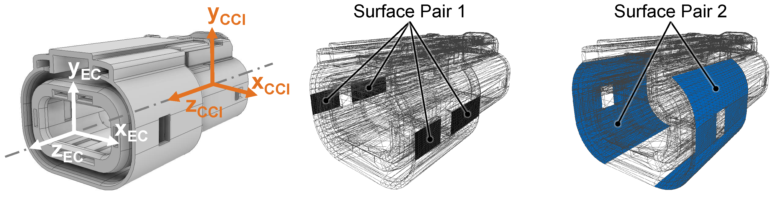
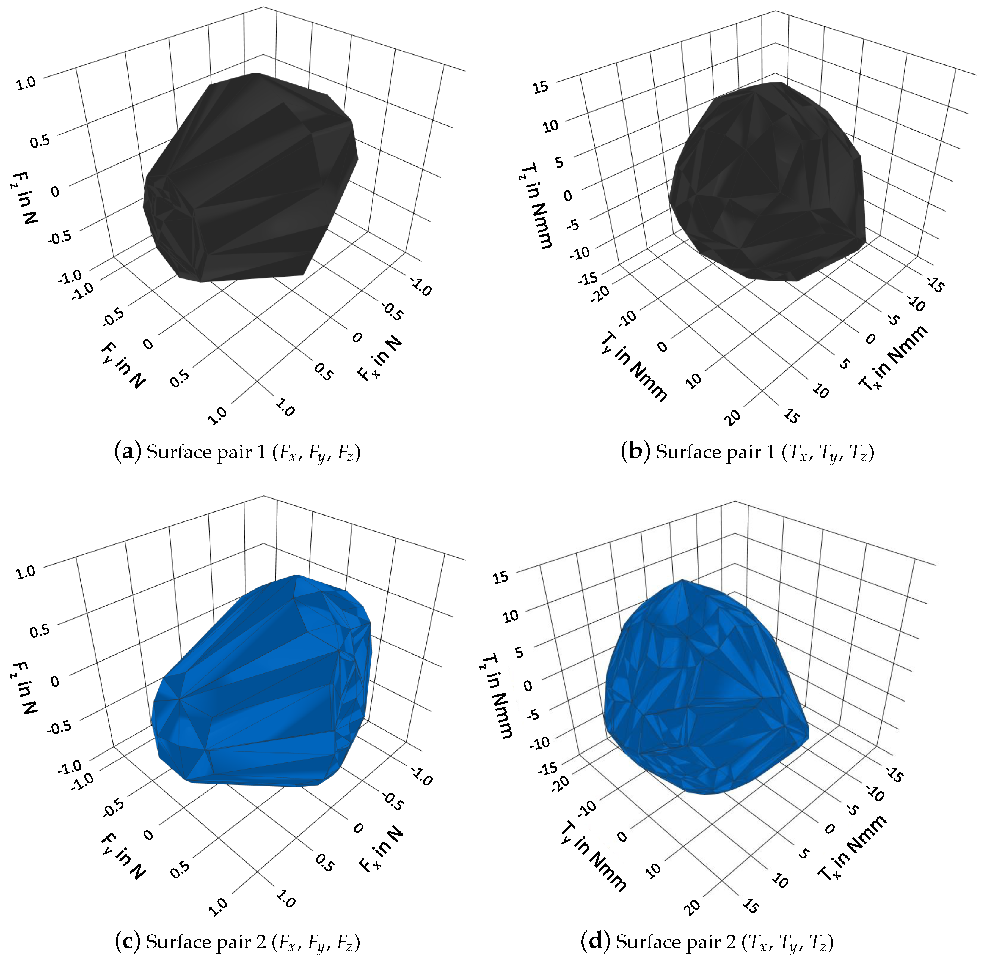
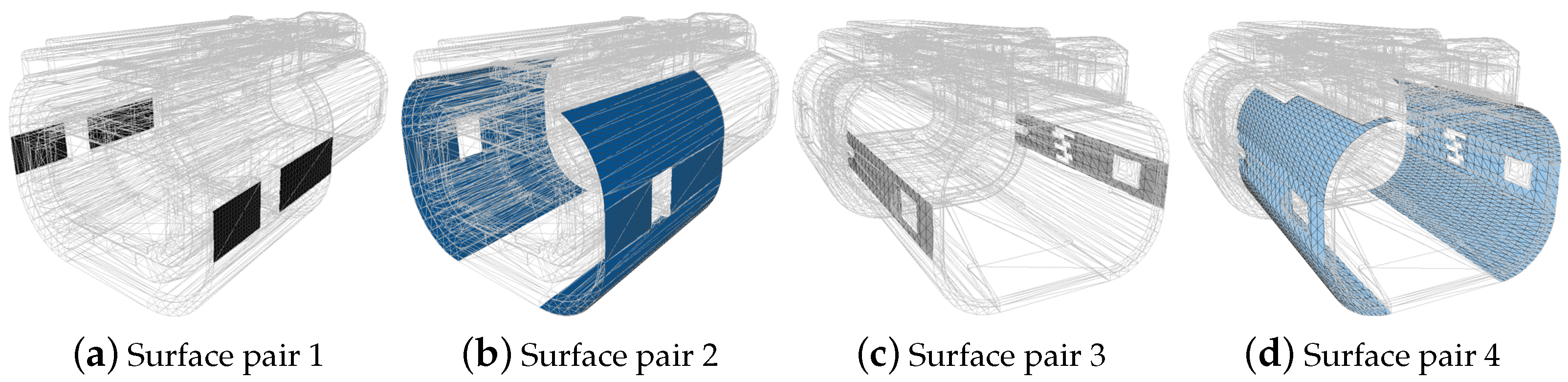
  • showing the effect of dynamic cable deformations on different surface pairs of a plug,
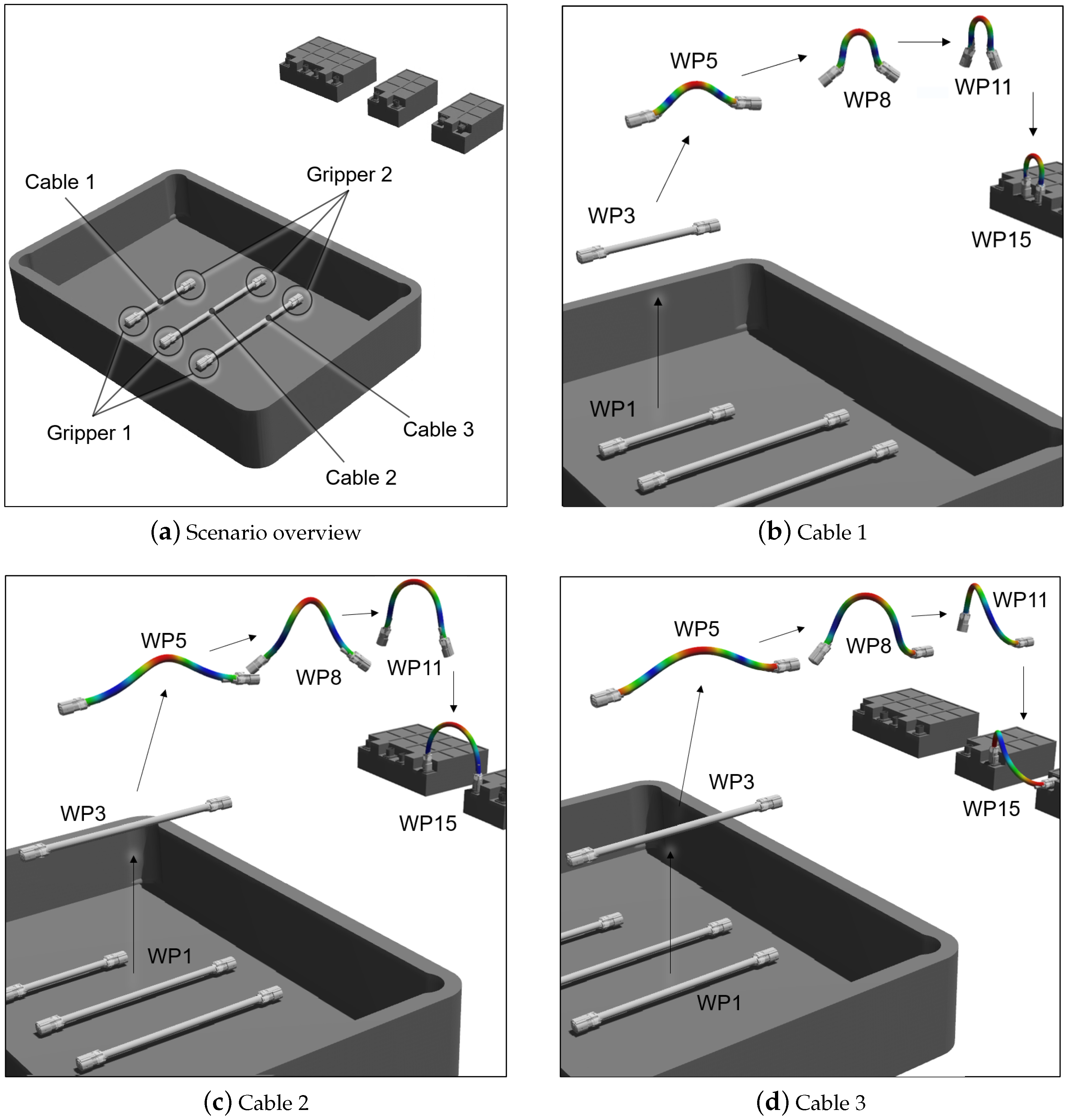
  • demonstrating a procedure to automatically generate a physics simulation scenario to sample the dynamic cable wrenches.

3. Methodology

After describing the broader context of the methodology (Section 3.1), a brief overview of the methodology is given (Section 3.2). Subsequently, the details are presented (Section 3.3 and Section 3.4) and the implementation is described (Section 3.5).

3.1. Broader Context

The overall goal of this methodology is to reduce the time, effort, and the required expertise during the design of gripper systems for ECs. In detail, this is to be achieved by simulatively estimating the required grasp force, quantifying the dynamic cable influence, and comparing surface pairs with each other. Thus, the required effort for iterative prototyping with time-consuming physical test series should be reduced.
In the context of production engineering, the methodology is applied at the stage of assembly planning. The EC CAD data, the product to be assembled, and the cable specifications are assumed to be known. The latter may already be known from the company’s own product development, obtained from the cable manufacturer, or determined on the basis of existing cable libraries.
Since cables have to be mated on both sides in the majority of industrial applications, this methodology considers the two-sided grasping, handling, and mating of pre-assembled ECs. Therefore, two robot systems and two gripper systems are envisaged. For each cable, they aim to simultaneously grasp the two plugs, handle and mate them into two sockets of a product. The methodology covers two-jaw parallel gripper systems. A gripper system consists of a gripper base and two gripper jaws. While commercially available systems are envisaged as the gripper base, the gripper jaws are to be designed individually for each plug resulting in force-closure surface contacts.

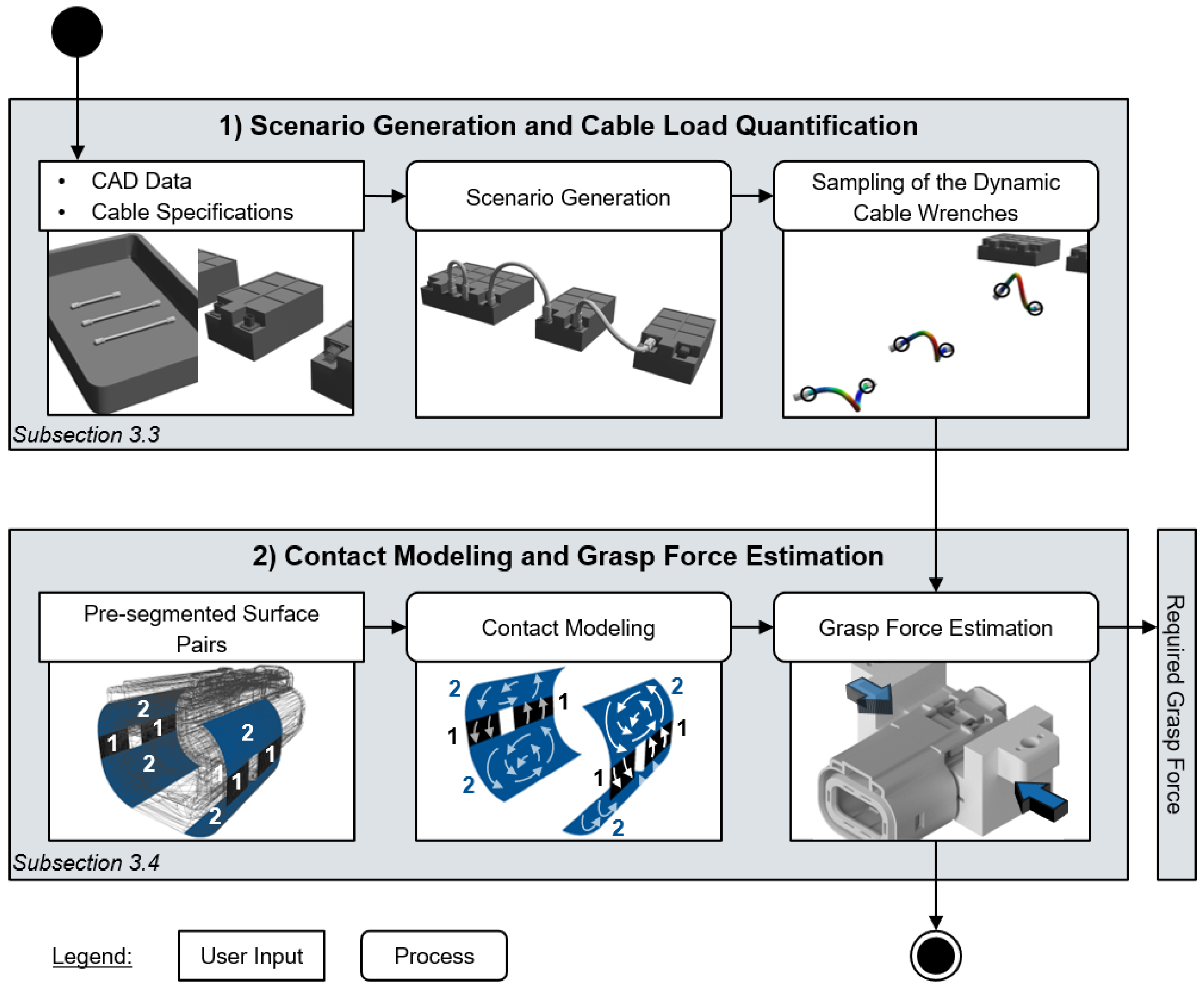
3.2. Methodology Overview

In this section, a brief overview of the methodology is given, which can be divided into two main steps, as shown in Figure 2.
The objective of step 1 is to quantify the mechanical impact of the cables on the plugs for a given assembly task. Step 2 then uses this data to estimate the required grasp force for different surface pairs of the two gripper systems.
In order to achieve these objectives, a physics simulation scenario is automatically generated in step 1. Thus, the cables are connected to the plugs and manipulated along predefined trajectories to be installed in a product. Thereby, the dynamic cable wrenches induced on the plugs are sampled. In step 2, the contact relations between the gripper jaws and the surface pairs of the plugs are modeled. This finally allows the dynamic cable wrenches determined in step 1 to be evaluated and the required grasp force to be estimated. Hence, a user can investigate the impact of the dynamic cable behavior on the grasping process. Thereupon, the robot trajectories can be adapted in case of unfavorable deformations and, thus, avoid peaks in the required grasp forces. Moreover, a user can make an informed decision for a surface pair and avoid overdimensioning.
In Section 3.3 and Section 3.4, the two steps of the methodology are explained in detail.

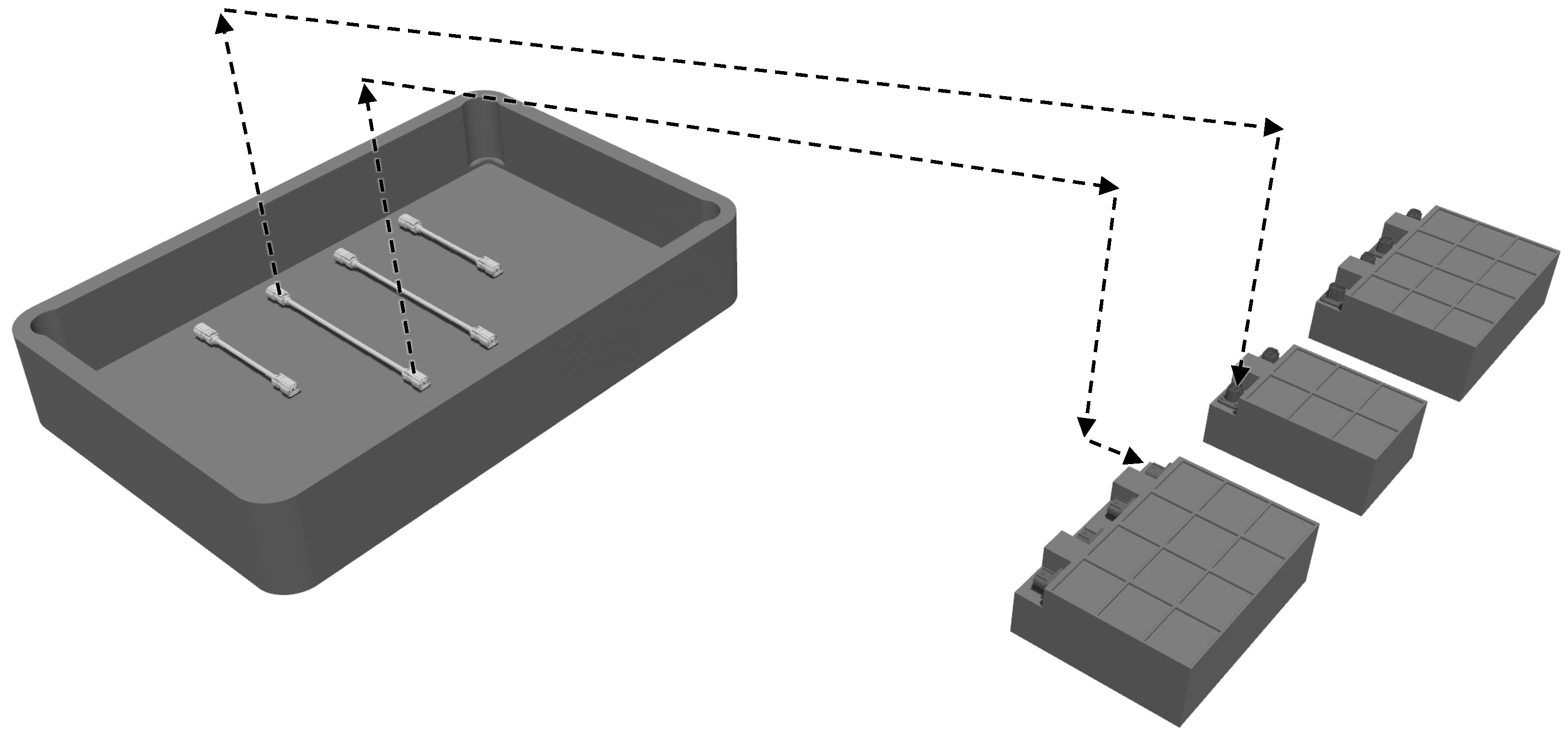
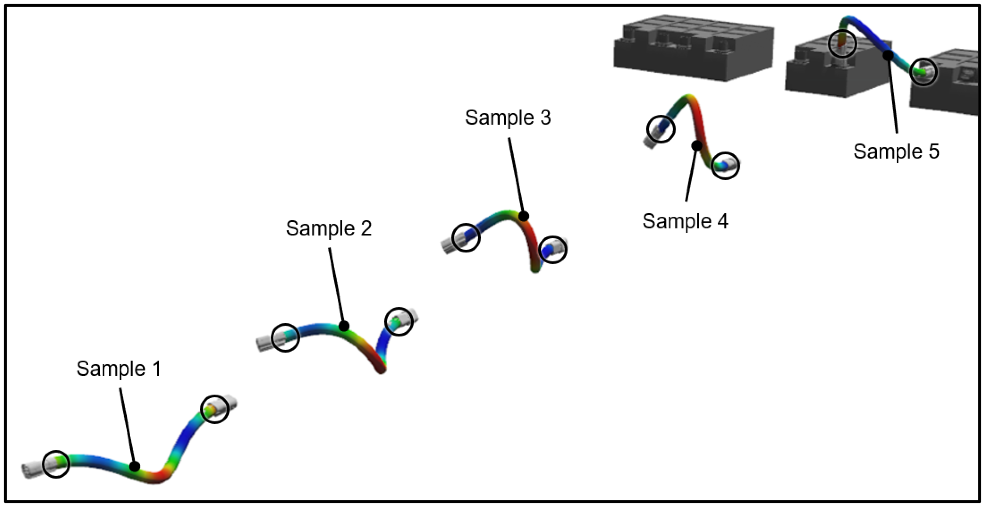
3.3. Scenario Generation and Cable Load Quantification

As a basis for the scenario generation in the physics simulation, data must first be provided by the user. This includes the CAD data of plugs and sockets, their supply, and the product to be assembled. In addition, the supply pose and mating pose are necessary for each plug. This data is typically already available, at least preliminarily, during assembly planning and can be derived from assembly planning software.
For the physics simulation in this work, high accuracy in modeling of the dynamic and mechanical cable behavior is required. A rough topological representation is, therefore, not sufficient. As shown by [30], for modeling DLOs, the nonlinear mechanics of elastic rod methods outperform other modeling techniques, such as the mass-spring method or the finite-element method, in terms of accuracy. Therefore, we build on software that is based on rod-based modeling in this work, more precisely on IPS Cable Simulation (https://flexstructures.com/products/ips-cable-simulation/, accessed on 22 February 2023). For an in-depth comparison of the different physics simulation techniques for DLOs, please refer to [30].
For the mechanical description of the cables, the parameters listed in Table 1 are required.
With the CAD data and cable parameters given, the scenario can be generated automatically. For this purpose, the CAD models are placed, and the cables are created. In each case, the two cable ends are connected to the two plugs. The cables are generated without deformation and load. Subsequently, two trajectories are initialized for each cable, mapping the temporal courses of the two grippers, as shown in Figure 3.
Linear movements are used for the removal of cables from the supply and the mating of the plugs into the sockets. The transfer motions in between up to the pre-pose for mating are carried out via straight-line translations. Thereby, necessary pose changes of the two plugs for mating occur with a constant rate of change in rotation. The two trajectories are synchronized in their velocity so that both plugs are mated into the sockets at the same time. The removal height from the supply and the pre-pose for mating can be configured individually.
The initialized trajectories can now be used to quantify the dynamic cable wrenches. For this, the user can select the number of waypoints (WPs) to be sampled. The quantity should be chosen depending on the length of the trajectories and the expected cable deformations. The cables are then manipulated along the trajectories, and the wrenches are tapped at each of the two cable ends in their local coordinate system, as shown in Figure 4.
The dynamic cable wrenches are subsequently evaluated by the contact model, which is described in the following section.

3.4. Contact Modeling and Grasp Force Estimation

As a basis to estimate the required grasp force for the cable wrenches, a contact model must first be built for each of the different surface pairs. In this work, we build on the novel contact model and its related framework developed by [11], which was studied in Section 2.1, mainly due to the following reasons: First, to the best of our knowledge, it is the only contact model which can model NSCs for robotic grasping. This is required for plugs, since their exterior surfaces are commonly curved. Second, it provides the ability to evaluate whether a grasp can withstand an external disturbance. This is beneficial to determine the required grasp force for a cable wrench.
The first three of the four steps described subsequently originate from the work of [11]. The description of these three steps should be regarded as a brief summary. For in-depth details, please refer to [11]. As input for this contact model, surface pairs from the CAD data of the plugs are generated. In Figure 5, an example of two different surface pairs for the plug of an EC is given. Moreover, the friction coefficient and pressure distribution for each contact surface have to be provided. The latter can be estimated based on common contact models, such as a uniform distribution or the Hertzian contact profile [32].
First, for each surface of each surface pair, the contact wrench is calculated, which is composed of a frictional wrench and a normal wrench. The latter is solely determined by the contact profile, but the former is also dependent on the relative motion between the gripper jaw and the workpiece. This relative motion is zero during a successful grasp. However, the higher an external disturbance is, the more likely a relative motion will occur. Therefore, so-called unit twists are modeled, which represent instantaneous motions. A unit twist is then used to calculate the linear velocity and its direction between the workpiece and the gripper jaw at an associated contact point. This information is subsequently used to calculate the frictional wrench. The normal wrench is basically determined via a given pressure distribution [11].
Second, the unit twists are sampled to calculate all frictional wrenches which a contact can transmit. To these possible wrenches, a limit surface model is then fitted in the six-dimensional space of the six wrench components, which is introduced as the 6-D limit surface (6DLS). As a 6DLS, a 6-D ellipsoid is used since it outperforms the convex quartic one. This 6-D ellipsoid is built for each surface of each surface pair with their given friction coefficient and pressure distributions [11].
Third, these 6DLS models are used to predict whether a grasp can withstand a given external disturbance. Therefore, the models are linearized for efficiency and sampled with vertices. They are then denormalized and overlaid with the associated normal wrenches. The contact wrenches generated so far in a local coordinate system are transformed into a common point of reference for all contact surfaces. Then, the GWS is calculated by computing the convex hull over the Minkowski sum of the contact wrenches. With the GWS given, it can be checked whether a given external disturbance can be withstood by the grasp. Therefore, it is evaluated whether the opposite of the external disturbance lies within the GWS. If this is the case, the grasp can withstand this external disturbance [11].
Fourth, the required grasp force for a given external disturbance is estimated for each surface pair inspired by [33]. For this purpose, the GWS is built for a grasp force of 1 Newton (N) as a basis. For each WP, the associated cable wrench and further wrenches (e.g., the mating force at the end of the task) are referenced to the EC coordinate system (see Figure 5), and superimposed. Each of these WPs is then evaluated individually. Inspired by [10,33,34], if the opposite of the external disturbance does not lie within the GWS, the latter is scaled until this is the case.
In order to scale the GWS, its intersection with the external disturbance has to be calculated. The GWS is bounded by several surfaces. Figure 6 shows a visualization of the GWSs of the two surface pairs introduced in Figure 5.
A single surface of the GWS is defined by a six-dimensional surface normal and its distance from the origin. For each of these surfaces, the scalar product is used to check whether it is intersected by the external disturbance. For each intersection, the proportion of the external disturbance is determined at which it intersects the surface. For the surface with the smallest proportion, the reciprocal of this proportion represents the scaling factor of the GWS. The external disturbance now reaches exactly to the boundary surface of the scaled GWS. The corresponding required grasp force can then be derived from the scaled GWS.
After determining the required grasp force for every surface pair and every WP, the course of the required grasp force over the trajectories can be depicted. With this course, a user has the main information to decide on a gripper basis and a surface pair. In addition, adjustments to the trajectories can be carried out if avoidable load peaks result from the cable deformation.

3.5. Implementation

The scenario generation and cable load quantification is implemented via the application programming interface (API) [35] provided by IPS Cable Simulation and written in the programming language Lua. Thereby, the CAD data, cable data, and position information are processed by the Lua code. From the scenario thus generated in IPS Cable Simulation, the forces and torques at all WPs are exported in tabular form for both grippers at their respective CCI. The contact modeling and grasp force estimation is built on the MATLAB code (https://github.com/martinajingyixu/non-planar-surface-contact, accessed on 2 January 2023) published in [11]. Here, the surface pairs are imported as stl files, which can be derived from common CAD software. The first two of the four steps presented in Section 3.4 proceed in MATLAB. Due to better performance and interfaces, step three is transferred to Python. Thereby, the GWS is built using the library ConvexHull (https://docs.scipy.org/doc/scipy/reference/generated/scipy.spatial.ConvexHull.html, accessed on 17 January 2023) as a counterpart to the library inhull in the original MATLAB code.
The fourth and last step is also implemented in Python, whereby the forces and torques from IPS Cable Simulation are used.

4. Results

The methodology presented is applied in this section using the example of high-voltage cables and ECs. First, a reference scenario is defined in order to compare different surface pairs, cables, and trajectories with each other (Section 4.1). Subsequently, the results obtained using the reference scenario are described (Section 4.2Section 4.4).

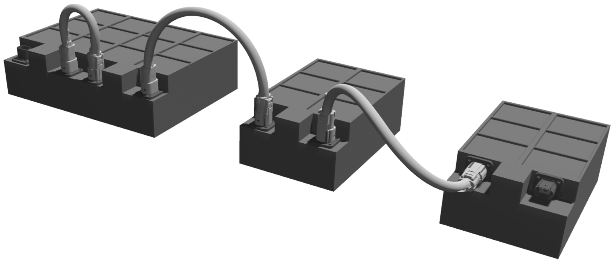
4.1. Reference Scenario

A simplified representation of the interconnection of battery modules serves as a reference scenario. For this purpose, one high-voltage plug—the one introduced in Figure 5—is used. Exemplarily, four different surface pairs are compared with each other; see Figure 7.
The wrenches induced by the cable on the plugs exert at the CCI, to which surface pairs 3 and 4 are closer than surface pairs 1 and 2. Inspired by [36], the cables are provided in a load carrier. Specifically, three high-voltage cables are used with the plug shown in Figure 7. A plug is attached to the cable. The three cables shall connect four battery modules in series. An overview of the reference scenario is shown in Figure 8a.
Each cable is simultaneously grasped at both plugs, manipulated along the automatically initialized trajectories, and mated to the associated sockets. This results in different deformations over time, as shown in Figure 8b–d. Since the weight force of the two plugs and the cable is negligible compared to the deformation effect, the gravity is set to zero. Moreover, a uniform pressure distribution and a friction coefficient of 0.5 are chosen for each contact. For each cable, its dynamic wrenches are sampled for both ends and at 15 WPs at a constant rate. WP 1 depicts a cable placed in the load carrier, and WP 15 represents the mounted state. In addition, to determine the required grasp force at each of the 15 WPs, two further estimations are performed. On the one hand, the required grasp force, if only the force to mate the plug to the socket, is taken into account. This mating force is simplified as a pure axial force in the negative z-direction of 75 N in the EC coordinate system and is known from the product specifications of the EC; compare Figure 5. On the other hand, the required grasp force for superimposing this mating force with the last cable wrenches at WP 15 is considered.
In Section 4.2 and Section 4.3, a set of three high-voltage cables with identical effective parameters is investigated. Subsequently, it is compared to another set in Section 4.4.

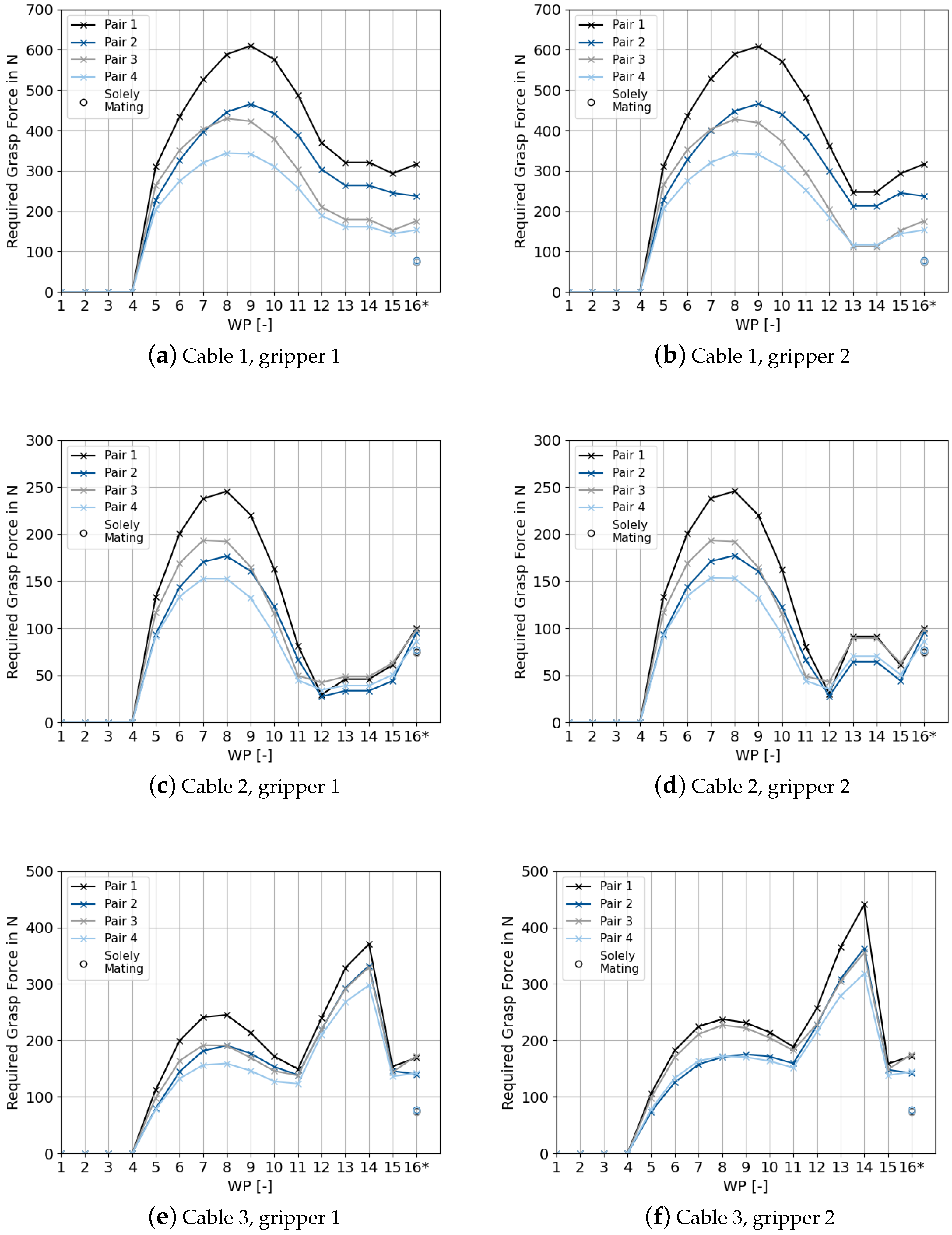
4.2. Grasp Analysis for High-Voltage Cables

The results for three high-voltage cables made of copper with a cross-section of 50 mm 2 are shown in Figure 9 for each of the two grippers.
For WPs 1–4, the required grasp force is zero since the cable is removed from the load carrier and manipulated solely vertically, and, therefore, does not undergo any deformation. From WP 5, the courses are strongly individual, especially when comparing the three cables. The correlation between the cable deformation and the required grasp force can be observed qualitatively using cable 2 as an example. Its deformation increases from WP 5 to WP 8 and then decreases again through WP 11; compare Figure 8c. This is reflected in the corresponding values for the required grasp force in Figure 9c,d. Moreover, qualitatively similar courses with different scaling of the four surface pairs are shown for one cable and one gripper. If we compare a planar surface with a non-planar one along the same axial plug position, the planar surface requires a higher grasp force for almost every WP. Moreover, the closer a surface pair lies with respect to the CCI, the lower its required grasp force is. This can be seen when comparing surface pairs 1 with 3 and 2 with 4. With a few exceptions, surface pairs 3 and 4 require less grasp force. This can be explained by the lower leverage of the CCI to surface pairs 3 and 4 compared to 1 and 2.
In addition, a qualitative comparison of two grippers reveals similar courses. In particular, this is the case for the predominant symmetrical deformations of cables 1 and 2, in which, primarily, a cable bending of 180 degrees occurs. However, cable 3 shows that asymmetrical deformations can amplify the variation in the grasp force courses, especially in the maximum values.
If we compare cable 1 and cable 2, which, primarily, undergo bending deformations but have different lengths, similar courses apart from their scaling can be observed. For cable 1, significantly higher grasp force values result due to its much smaller bending radius.
To analyze the superposition of the cable wrench in the mounted state and the mating force, the transition from WP 15 to 16* is observed. It can be noted that the impact of the mating force on the required grasp force depends on the characteristics of the cable wrench already acting in the mounted state. For example, the mating force has a stronger influence on the required grasp force for cable 2 than for cables 1 and 3. This is indicated by the increase from WP 15 to WP 16*. Solely considering the mating force while neglecting the cable wrenches is generally not allowed. Depending on the deformation, a multiple of the required grasp force may be necessary by the cable compared to the mating, as is the case for cables 1 and 3, for example. For all courses in Figure 9, it is apparent that the automatically generated standard trajectories each demand a grasp force that significantly exceeds the minimum required grasp force. The latter is considered to be that of WP 16* since it cannot be lowered without changing the EC, the product, or the cable.

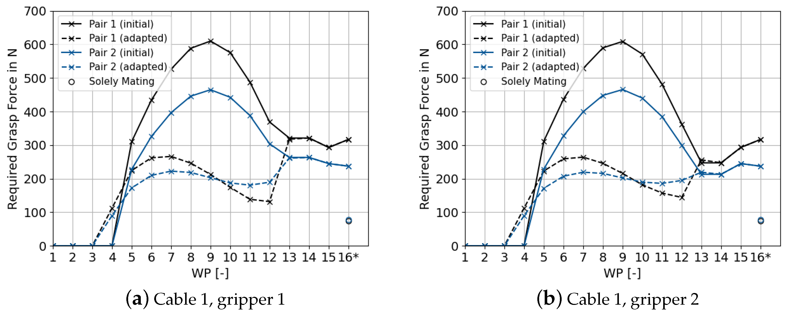
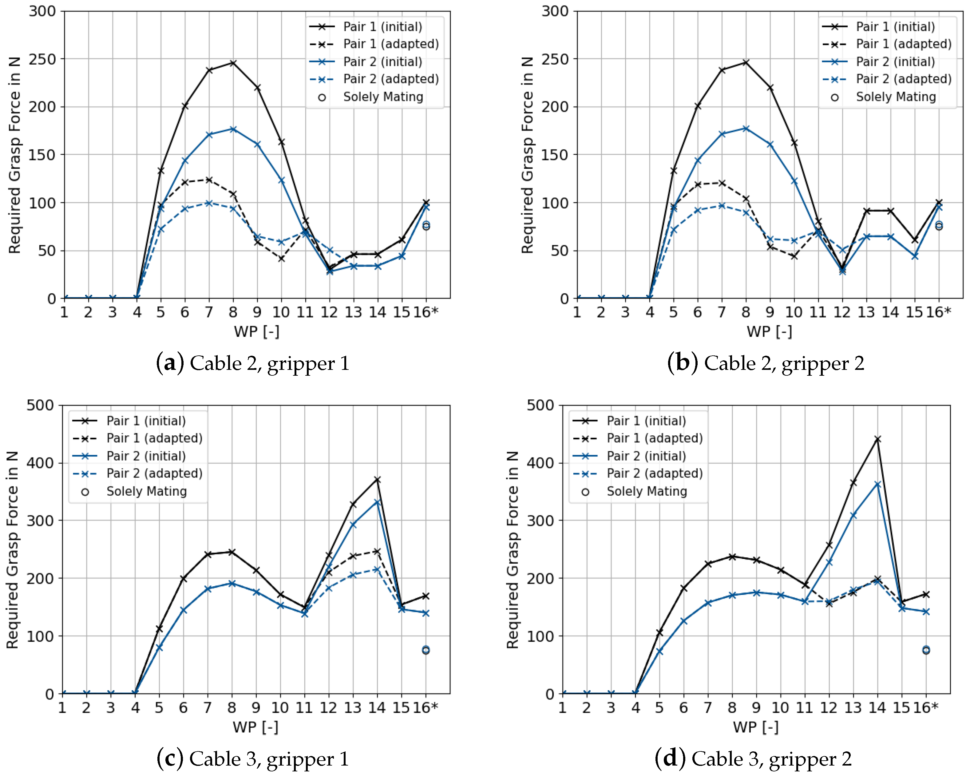
4.3. Manual Adaptation of the Automatically Generated Trajectories

The results from Section 4.2 enable identification of WPs with avoidable high grasp force. Using this information, a user can adjust the two trajectories to reduce the cable deformation and, thus, the magnitude of the cable wrenches. For example, for cable 1 in Figure 9, this is particularly the case for WPs 6–12. Therefore, a manual adjustment of the trajectories is conducted. Precisely, a temporal delay is applied to the trajectory of gripper 1 at WPs 5–12 so that the unfavorable cable deformation is avoided. Towards WP 13, both grippers are temporally synchronized so that they follow the initial trajectories. The corresponding grasp forces are shown in Figure 10.
By comparing the initial trajectories with the adapted ones, it can be observed that the required grasp force is significantly reduced for WPs 5–12. For gripper 1, WPs 13–15 still offer a slight potential for improvement compared to WP 16* and, thus, avoidance of overdimensioning. For cables 2 and 3, the required grasp force can also be significantly reduced by manually adapting the trajectories; see Figure A1 in Appendix A.
So far, different grasping surfaces, trajectories and cable lengths have been compared. In addition, the effective cable parameters affect the required grasp force, which is discussed below.

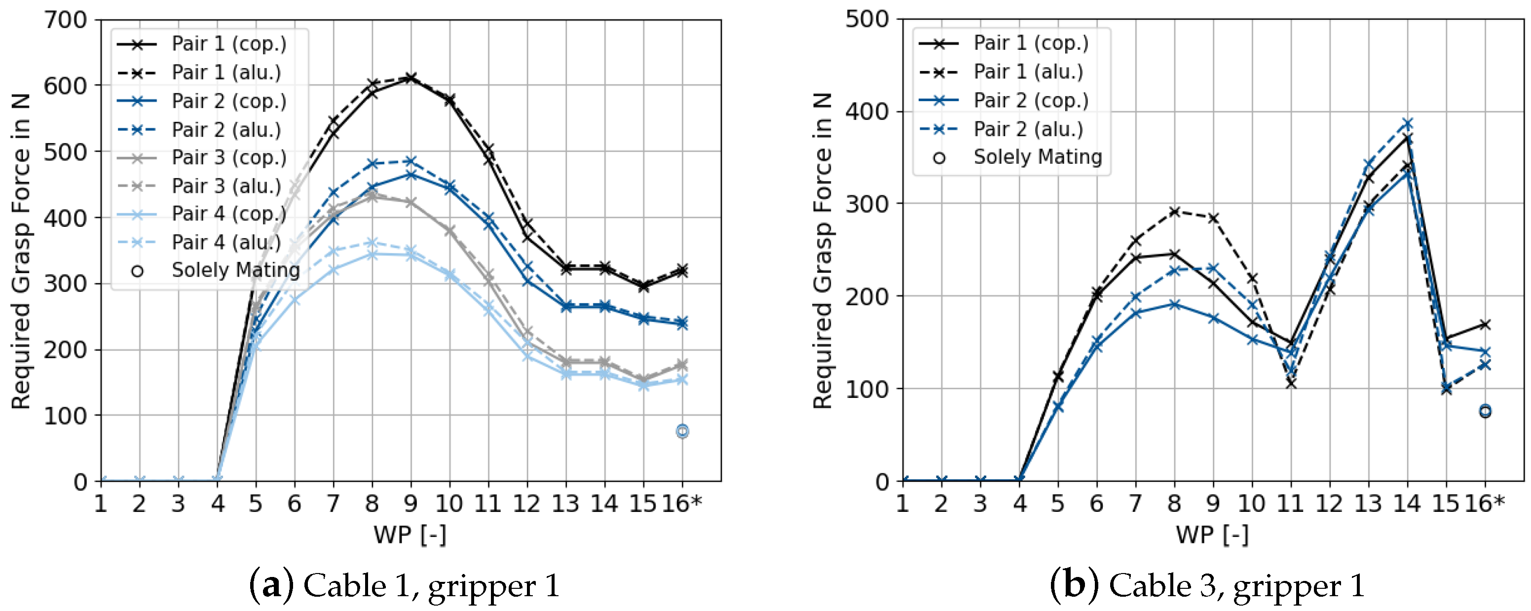
4.4. Comparison of Different High-Voltage Cables

In order to analyze the effects of using different cable parameters on the course of the required grasp force, the previously used high-voltage cable made of copper is compared with one made of aluminum. The effective cable parameters of the two instances are depicted in Table 2. The initialized trajectories presented in Section 4.1 are applied to both cable instances. The results can be found in Figure 11.
The remaining cable-gripper combinations are shown in Figure A2 in Appendix A. For Figure 11a, it can be observed that, for a predominant bending load with only minor values in the other wrench components, similar courses are obtained. This can be explained by the fact that mainly the similar bending stiffness E I 1 / 2 takes effect, whereas the tensile stiffness E A and the torsional stiffness G J have only a minor impact. In addition to bending, cable 3 in Figure 11b exhibits further deformation components to gripper 1. Therefore, different values for both cables result.

5. Discussion

This chapter first discusses the key findings within the presented results. Subsequently, the limitations and potential solution approaches of the developed methodology will be elaborated.

5.1. Key Findings

The presented methodology allows us to quantify the mechanical cable influence on the grasping process of ECs. The results demonstrate that the required grasp force significantly depends on the current deformation state of a cable. Thus, a grasp force estimation solely based on the mating force is generally not permissible for pre-assembled cables with ECs. In addition to the cable deformation, the selection of surface pairs affects the required grasp force. For the examples shown, the required grasp force can differ by up to a factor of approximately 1.8 ; compare Figure 9a. Moreover, in general, the required grasp force should be evaluated individually for both grippers. Although there are qualitative similarities between the courses for both grippers (see Figure 9), their maxima may differ significantly for asymmetrical cable deformations; compare Figure 9e,f. Furthermore, for most WPs of the considered assembly task, the required grasp force is lower for a non-planar surface pair compared to its planar alternative; see surface pairs 1 and 2, as well as surface pairs 3 and 4. In general, each combination of a surface pair and a cable wrench results in an individual contact situation. The cable wrench, in turn, significantly depends on the trajectories and the cable parameters. In conclusion, it can be stated that each of the assembly tasks considered should be evaluated individually due to the large number of parameters affecting the required grasp force. Transferring already estimated courses from one surface pair to another or from one cable to another is generally not possible without further effort. The results also indicate that the proposed automated scenario generation in a physics simulation is suitable for simulating the dynamic cable wrenches with little user input. However, the initially generated trajectories can cause unfavorable cable deformations. Thus, in most cases, manual adjustments are required.

5.2. Limitations and Potential Solution Approaches

The presented methodology is subject to the boundary conditions and assumptions of the contact model developed by [11]. In Section 2.1, its most important aspects were presented. In addition, the model underlies other influencing factors, such as the mesh resolution of the contact surfaces. The authors show that the error rate decreases sharply as the number of triangular mesh elements increases and, for example, is less than 4% for 300 triangular mesh elements [11]. Moreover, during experimental testing, external force disturbances along the grasp axis were not evaluated by the authors [11].
Additionally, the same uniform pressure distribution is used for all WPs in this work. Theoretically, the accuracy of the grasp force estimation could be further increased by performing finite element analysis to determine the pressure distribution at each WP. However, this would require high manual effort, which is not compatible with the objective of this work. Determining a specific pressure distribution for each WP using a contact model would also be difficult in advance since the six cable wrench components are individually combined for each WP. Thus, the use of the same pressure distribution for all WPs seems to be a suitable compromise.
For the results of the plug used in this work, the contact model for NSCs is also applied to planar contacts; compare surface pairs 1 and 3. The results for the pure mating force for surface pairs 1 and 3, for example, match the analytical calculation exactly. In general, further investigation is needed to determine the effect of possible fitting errors of the 6DLS model when applied to planar contacts. If the fitting error exceeds a specific threshold, a planar contact model could be applied to these.
Furthermore, the friction coefficient is often subject to variation in reality [4], and, therefore, its lower limit should be used [11]. Moreover, possible deformations of the gripper jaws during grasping are not taken into account. These depend on the topology of the gripper jaws to be designed.
In addition, in the reference scenario, we have assumed the mating force to be simplified in the axial direction. The modeling of this force has to be adapted depending on the intended mating strategy. As shown by [15], further forces and torques can occur during mating. In our framework, their values could be added to the external wrench of WP 16* in the EC coordinate system. If mating is performed by an external device at the gripper, such as a lifting cylinder, the mating force does not have to be applied—in this case, only the cable wrenches operate.
Moreover, the cables are currently generated in a straight line in the physics simulation scenario. The generation of curved cable shapes could be implemented with the procedure described in [37]. In addition, the trajectories are currently referenced to the CCI coordinate system and must first be adjusted by the offset to the selected surface pair for use on the robot.
In summary, the courses in this paper are subject to a number of superimposing uncertainties. The courses should, therefore, be regarded as a possibility for comparative estimation. It is, therefore, essential to consider ordinary safety factors in the required grasp force. The introduced reference scenario of interconnecting battery modules is to be seen as a synthetically generated example for the purpose of the investigations in this work. The dimensions of parts, the combinations of cable instances and ECs, and the position of the CCI, etc., are not based on real product specifications.

6. Conclusions and Outlook

We presented a methodology for grasp analysis for the robot-based manipulation of pre-assembled cables with ECs. The novel contribution is the combination of a contact model for robotic grasping with a physics simulation for DLOs. The latter is used to simulate the mechanical impact of dynamic cable deformations on the grasping process, which is particularly important for cables with high stiffness parameters. For this purpose, a procedure to automatically generate a scenario in a physics simulation based on CAD data and cable specifications is presented. Subsequently, the contact model estimates the required grasp force for the dynamic cable deformation. Based on the simulation results, a user can choose a suitable gripper base, select a surface pair to grasp the EC, and re-plan the assembly task. The methodology opens up the potential to reduce time-consuming prototyping and experimentation, especially for re-scheduling in the event of changes to the product and the assembly task. In future work, the methodology could be used to analyze the one-sided grasping of ECs with free cable movement. In contrast to this work, a significant influence is to be expected from the cable mass due to its leverage on the surface pairs. In addition, the mechanical impact of the cable deformation due to the one-sided manipulation offers potential for investigation. The routing of cables by connecting them to clamps is also conceivable and generally possible using IPS Cable Simulation. It is also feasible to extend this work to include collisions between the cable and rigid obstacles involved in an assembly task. For the trajectory generation, a combination with the path planning approach for DLOs presented by [26] (see Section 2.3) could be suitable. Furthermore, this work is expected to be easily transferable to other DLO assembly applications, such as hydraulic hoses. This is due to the high universality of the contact model used and the physics simulation being applicable to many types of DLOs.
There is further research potential related to automating the adaptation of trajectories, which is currently executed manually. Thereby, the extent to which these grasp force-minimal considerations can be combined with classical robotic path planning could be investigated. In addition, a finite element analysis could be performed at reasonable cost to determine the pressure distribution at the WP with the highest required grasp force. Furthermore, this method of analysis could be used to determine the permissible grasp force without damaging the EC, e.g., based on the surface pressure applied [4]. This upper limit of the grasp force should be checked before a surface pair is finally selected. In addition, it is conceivable to integrate further boundary conditions of the assembly task that affect the gripper system, e.g., different solutions for the cable supply.

Author Contributions

Conceptualization, D.G.; methodology, D.G. and J.D.; software, D.G. and L.M.; validation, D.G. and L.M.; formal analysis, D.G.; investigation, D.G.; resources, R.D.; data curation, D.G.; writing—original draft preparation, D.G.; writing—review and editing, J.D. and R.D.; visualization, D.G.; supervision, R.D.; project administration, J.D.; funding acquisition, R.D. All authors have read and agreed to the published version of the manuscript.

Funding

This research was funded by the Bavarian Ministry of Economic Affairs, Regional Development, and Energy (StMWi), as part of the project “RoMaFo – Roboterassistenzsystem und maschinelles Sehen zur Montage von formlabilen Bauteilen bei kundenindividuellen Produkten” (DIK-1908-0002// DIK0109/01).

Institutional Review Board Statement

Not applicable.

Informed Consent Statement

Not applicable.

Data Availability Statement

The data of this study are available on request from the corresponding author.

Acknowledgments

The authors sincerely thank Jingyi Xu for the highly helpful discussions concerning the works [11,33]. In addition, we express our gratitude to the authors of [11] for the publication of the associated code. Moreover, the authors would like to gratefully acknowledge the company flexstructures GmbH for providing a test license of the software IPS Cable Simulation. Without the honorees, the work presented would not have been possible.

Conflicts of Interest

The authors declare no conflict of interest.

Appendix A. Results of the Grasp Force Estimation

Figure A1. Comparison of the required grasp force with trajectories initially and automatically generated as well as for manual adaptations. For cable 2, a temporal delay of 0.08 s is conducted for gripper 1 at WPs 5–12. For cable 3, the critial WPs are especially 13–14. To reduce the deformation at these WPs, a delay of 0.2 s is added for gripper 2 between WP 11 and 12 before the solely vertical movement; compare Figure 8. The initial grasp force courses correspond to the ones shown in Figure 9. For clarity, the subplots are only depicted for surface pairs 1 and 2. WP 16* represents the superposition of WP 15 with the force for mating the plug to the socket.
Applsci 13 06462 g0a1
Figure A2. Comparison of the required grasp force for two different high-voltage cables made of copper and aluminum, each with a cross-section of 50 mm2. The cables are each exposed to the same trajectories. For clarity, subplots (bd) are only depicted for surface pairs 1 and 2. WP 16* represents the superposition of WP 15 with the force for mating the plug to the socket.
Applsci 13 06462 g0a2

References

  1. Honarpardaz, M.; Tarkian, M.; Ölvander, J.; Feng, X. Finger design automation for industrial robot grippers: A review. Robot. Auton. Syst. 2017, 87, 104–119. [Google Scholar] [CrossRef]
  2. Gebauer, D.; Dirr, J.; Daub, R. Automated Design of Gripper Systems for Electrical Connectors (submitted). In Proceedings of the CIRP ICME, Naples, Italy, 13–15 July 2022. [Google Scholar]
  3. Hesse, S. Greifertechnik: Effektoren für Roboter und Automaten; Carl Hanser: Munich, Germany, 2011. [Google Scholar]
  4. Schmalz, J. Rechnergestützte Auslegung und Auswahl von Greifersystemen; Utzverlag: Munich, Germany, 2018. [Google Scholar]
  5. Böger, T. Beitrag zur Projektierung von Greifelementen für die Handhabung flächiger, biegeweicher Materialien; Praxiswissen Service: Dortmund, Germany, 1998. [Google Scholar]
  6. Kao, I.; Lynch, K.M.; Burdick, J.W. Contact modeling and manipulation. In Springer Handbook of Robotics; Siciliano, B., Khatib, O., Eds.; Springer: Berlin/Heidelberg, Germany, 2016; pp. 931–954. [Google Scholar]
  7. Prattichizzo, D.; Trinkle, J.C. Grasping. In Springer Handbook of Robotics; Siciliano, B., Khatib, O., Eds.; Springer: Berlin/Heidelberg, Germany, 2016; pp. 955–988. [Google Scholar]
  8. Miller, A.T.; Allen, P.K. GraspIt! A Versatile Simulator for Robotic Grasping. IEEE Robot. Autom. Mag. 2004, 11, 110–122. [Google Scholar] [CrossRef]
  9. Ferrari, C.; Canny, J. Planning Optimal Grasps. In Proceedings of the IEEE International Conference on Robotics and Automation, Nice, France, 12–14 May 1992; pp. 2290–2295. [Google Scholar]
  10. Lin, Y.; Sun, Y. Task-Based Grasp Quality Measures for Grasp Synthesis. In Proceedings of the IEEE/RSJ International Conference on Intelligent Robots and Systems (IROS), Hamburg, Germany, 28 September–2 October 2015; pp. 485–490. [Google Scholar]
  11. Xu, J.; Aykut, T.; Ma, D.; Steinbach, E. 6DLS: Modeling Nonplanar Frictional Surface Contacts for Grasping Using 6-D Limit Surfaces. IEEE Trans. Robot. 2021, 37, 2099–2116. [Google Scholar] [CrossRef]
  12. Ji, W.; Tang, C.; Xu, B.; He, G. Contact force modeling and variable damping impedance control of apple harvesting robot. Comput. Electron. Agric. 2022, 198, 107026. [Google Scholar] [CrossRef]
  13. Ji, W.; Zhang, J.; Xu, B.; Tang, C.; Zhao, D. Grasping mode analysis and adaptive impedance control for apple harvesting robotic grippers. Comput. Electron. Agric. 2021, 186, 106210. [Google Scholar] [CrossRef]
  14. Xu, J.; Hou, Z.; Liu, Z.; Qiao, H. Compare Contact Model-based Control and Contact Model-free Learning: A Survey of Robotic Peg-in-hole Assembly Strategies. arXiv 2019, arXiv:1904.05240. [Google Scholar] [CrossRef]
  15. Song, H.C.; Kim, Y.L.; Lee, D.H.; Song, J.B. Electric connector assembly based on vision and impedance control using cable connector-feeding system. J. Mech. Sci. Technol. 2017, 31, 5997–6003. [Google Scholar] [CrossRef]
  16. Ortner, M.; Gadringer, S.; Gattringer, H.; Mueller, A.; Naderer, R. Automatized Insertion of Multipolar Electric Plugs by Means of Force Controlled Industrial Robots. In Proceedings of the 25th IEEE International Conference on Emerging Technologies and Factory Automation (ETFA), Vienna, Austria, 8–11 September 2020; pp. 1465–1472. [Google Scholar] [CrossRef]
  17. Yumbla, F.; Yi, J.S.; Abayebas, M.; Shafiyev, M.; Moon, H. Tolerance dataset: Mating process of plug-in cable connectors for wire harness assembly tasks. Intell. Serv. Robot. 2020, 13, 159–168. [Google Scholar] [CrossRef]
  18. Sanchez, J.; Corrales, J.A.; Bouzgarrou, B.C.; Mezouar, Y. Robotic manipulation and sensing of deformable objects in domestic and industrial applications: A survey. Int. J. Robot. Res. 2018, 37, 688–716. [Google Scholar] [CrossRef]
  19. Nadon, F.; Valencia, A.J.; Payeur, P. Multi-Modal Sensing and Robotic Manipulation of Non-Rigid Objects: A Survey. Robotics 2018, 7, 74. [Google Scholar] [CrossRef]
  20. Herguedas, R.; López-Nicolás, G.; Aragüés, R.; Sagüés, C. Survey on multi-robot manipulation of deformable objects. In Proceedings of the 24th IEEE International Conference on Emerging Technologies and Factory Automation (ETFA), Zaragoza, Spain, 10–13 September 2019; pp. 977–984. [Google Scholar] [CrossRef]
  21. Hermansson, T.; Bohlin, R.; Carlson, J.S.; Söderberg, R. Automatic assembly path planning for wiring harness installations. J. Manuf. Syst. 2013, 32, 417–422. [Google Scholar] [CrossRef]
  22. Hermansson, T.; Bohlin, R.; Carlson, J.S.; Söderberg, R. Automatic routing of flexible 1D components with functional and manufacturing constraints. Comput.-Aided Des. 2016, 79, 27–35. [Google Scholar] [CrossRef]
  23. Du, H.; Jiang, Q.; Xiong, W. Computer-assisted assembly process planning for the installation of flexible cables modeled according to a viscoelastic Cosserat rod model. Proc. Inst. Mech. Eng. Part B J. Eng. Manuf. 2022. [Google Scholar] [CrossRef]
  24. Roussel, O.; Taïx, M. Deformable Linear Object manipulation planning with contacts. In Proceedings of the IEEE/RSJ International Conference on Intelligent Robots and Systems (IROS)—Robot Manipulation: What Has Been Achieved and What Remains to Be Done? Chicago, IL, USA, 14–18 September 2014. [Google Scholar]
  25. Zhou, H.; Lu, Q.; Qian, J. Representation of Cable Harness for Assembly Sequence Planning. In Proceedings of the IEEE International Conference on Advanced Robotics and Mechatronics, Guilin, China, 09–11 July 2022; pp. 886–891. [Google Scholar] [CrossRef]
  26. Leão, G.; Sousa, A.; Dinis, D.; Veiga, G. Simulated Mounting of a Flexible Wire for Automated Assembly of Vehicle Cabling Systems. In Proceedings of the ROBOT2022: Fifth Iberian Robotics Conference, Zaragoza, Spain, 23–25 November 2022; pp. 385–397. [Google Scholar] [CrossRef]
  27. Yang, Y.; Stork, J.A.; Stoyanov, T. Learning differentiable dynamics models for shape control of deformable linear objects. Robot. Auton. Syst. 2022, 158, 104258. [Google Scholar] [CrossRef]
  28. Zhang, X.; Li, C.; Xi, N. Cable Assembly Based on Robot Manipulation and Control. Proceedings of 12th IEEE International Conference on CYBER Technology in Automation, Control, and Intelligent Systems, Baishan, China, 27–31 July 2022; pp. 597–602. [Google Scholar] [CrossRef]
  29. Lin, X.; Wang, Y.; Olkin, J.; Held, D. SoftGym: Benchmarking Deep Reinforcement Learning for Deformable Object Manipulation. Proceedings of 4th Conference on Robot Learning, Cambridge, MA, USA, 16–18 November 2020; pp. 432–448. [Google Scholar] [CrossRef]
  30. Du, H.; Xiong, W.; Wang, H.; Wang, Z. A review: Virtual assembly of flexible cables based on physical modeling. Assem. Autom. 2020, 40, 293–304. [Google Scholar] [CrossRef]
  31. Industrial Path Solutions. User Manual Version 2022-R1 n.p; Industrial Path Solutions: Gothenburg, Sweden, 2021. [Google Scholar]
  32. Hertz, H. Über die Berührung fester elastischer Körper und über die Härte. Verhandlungen des Vereins zur Beförderung des Gewerbfleißes; Verein zur Beförderung des Gewerbefleisses: Berlin, Germany, 1882; pp. 449–463. [Google Scholar]
  33. Xu, J. Modeling Nonplanar Frictional Surface Contacts for Robust Robot Grasping (submitted). Ph.D. Thesis, Technical University of Munich, Munich, Germany, 2023. [Google Scholar]
  34. Lin, Y.; Sun, Y. Grasp planning to maximize task coverage. Int. J. Robot. Res. 2015, 34, 1195–1210. [Google Scholar] [CrossRef]
  35. Fraunhofer-Chalmers Centre. IPS Cable Simulation: API for Lua Scripting in IPS 2022-R1; Fraunhofer-Chalmers Centre: Gothenburg, Sweden, 2021. [Google Scholar]
  36. Dirr, J.; Gebauer, D.; Daub, R. Localization and Grasp Planning for Bin Picking of Deformable Linear Objects (submitted). In Proceedings of the CIRP ICME, Naples, Italy, 13–15 July 2022. [Google Scholar]
  37. Dirr, J.; Gebauer, D.; Yao, J.; Daub, R. Automatic Image Generation Pipeline for Instance Segmentation of Deformable Linear Objects. Sensors 2023, 23, 3013. [Google Scholar] [CrossRef] [PubMed]
Figure 1. Synthetic example of interconnected battery modules using ECs and high-voltage cables. In the mounted state, the three cables result in different deformation shapes.
Applsci 13 06462 g001
Figure 2. Overview of the methodology of this work. The first step automatically generates a scenario in a physics simulation using CAD data and cable specifications. As a result, the cable wrenches induced by the cable on the two plugs and, thus, on the two grippers, are sampled. In the second step, the required grasp force to transfer these dynamic cable wrenches is estimated. For this purpose, a contact model is built for multiple pre-segmented surface pairs.
Applsci 13 06462 g002
Figure 3. Exemplary representation of an automatically generated assembly scenario in the software IPS Cable Simulation. The dashed arrows show the initialized trajectories along which the two plugs of one cable are manipulated by two robot systems.
Applsci 13 06462 g003
Figure 4. Visualization of sampling dynamic cable wrenches. A cable is deformed during the manipulation. This is indicated by the local curvature values of the cable during the manipulation, which are represented in color (red: high, blue: low). The varying deformations lead to different wrenches induced by the cable on the plugs at their interfaces, which are marked by black circles. The two gripper systems have to transmit these dynamic wrenches.
Applsci 13 06462 g004
Figure 5. Example of a high-voltage plug (https://www.te.com/deu-de/product-4-2103015-1.html, accessed on 9 February 2023). Its CAD data (left) is used to derive different surface pairs, as shown in the middle (surface pair 1) and on the right (surface pair 2). On the left, the convention of this work for the coordinate system of the plug of the EC (white, EC) and the cable-connector-interface (orange, CCI) are shown.
Applsci 13 06462 g005
Figure 6. Exemplary representation of the convex hull of the GWSs of surface pair 1 (black) and surface pair 2 (blue) of the EC shown in Figure 5 with respect to the coordinate system EC, a grasp force of 1 N, and a friction coefficient of 0.5 . For visualization purposes, (a,c) show the force components F x , F y , and F z of the six-dimensional GWS projected into the three-dimensional space. Analogously, (b,d) show the projection of the three torque components T x , T y , and T z .
Applsci 13 06462 g006
Figure 7. Four different surface pairs of a high-voltage plug generated from its CAD data; compare Figure 5. Surface pairs 1 and 3 have planar surfaces, whereas surface pairs 2 and 4 result in NSCs with the gripper jaws.
Applsci 13 06462 g007
Figure 8. Application scenario of interconnecting battery modules via high-voltage ECs. (a) gives an overview of the automatically generated scenario, in which three high-voltage cables are provided in a load carrier in order to interconnect four battery modules. (bd) show the discrete time steps 1 (supply), 3, 5, 8, 11, and 15 (mounted state) of the trajectories along which the three cables are manipulated and consequently deformed. Cable 1 (b) and cable 2 (c) are mounted with a bend of 180 degrees around the same axis, and cable 3 (d) with two bends of 90 degrees each around two different axes. For each cable and each WP, the local curvature is color-coded individually (red: high, blue: low). At WPs 1 and 3, the cables are not color-coded, because their local curvature is close to zero here. The deformation begins after WP 4.
Applsci 13 06462 g008
Figure 9. Required grasp forces of the scenario shown in Figure 8 of the three different cables with two grippers each, differentiated for the four surface pairs of Figure 7. WP 1 represents the supply of a cable, and WP 15 is the mounted cable. WP 16* represents the superposition of WP 15 with the force for mating the plug to the socket.
Applsci 13 06462 g009
Figure 10. Comparison of the required grasp force for cable 1 with the initialized trajectories as well as manually adapted between WPs 5 and 12. The initial grasp force courses correspond to the ones shown in Figure 9a,b. For clarity, only surface pairs 1 and 2 are shown. WP 16* represents the superposition of WP 15 with the force for mating the plug to the socket.
Applsci 13 06462 g010
Figure 11. Comparison of the required grasp forces for two different high-voltage cables made of copper and aluminum, each with a cross-section of 50 mm2. Both cables are manipulated along the same trajectories. WP 16* represents the superposition of WP 15 with the force for mating the plug to the socket.
Applsci 13 06462 g011
Table 1. Effective parameters to describe a cable mechanically in the software IPS Cable Simulation. If a cable has different bending characteristics in both material directions, bending stiffness 1 and 2 show different values [31].
ParameterAbbreviationUnit
Tensile stiffness E A N
Bending stiffness 1 E I 1 Nm 2
Bending stiffness 2 E I 2 Nm 2
Torsional stiffness G J Nm 2
Length density ρ L kg m
Table 2. Effective parameters of two high-voltage cables (©fleXstructures GmbH 2021) from an exemplary database of IPS Cable Simulation. Both cables feature a cross-section of 50 mm 2 . Due to their circular cross-section, both cables have equal bending stiffnesses E I 1 and E I 2 along both material directions [31] and, thus, are summarized to E I 1 / 2 . The cables differ significantly in their tensile stiffness E A and torsional stiffness G J , whereas the bending stiffness E I 1 / 2 only deviates slightly. Note that the effective parameters cannot be derived solely from the conductor since the material mix of conductor and isolation is crucial.
Conductor EA EI 1 / 2 GJ
Copper13,406,400 N0.095109 Nm 2 0.0922964 Nm 2
Aluminum4,483,500 N0.0955892 Nm 2 0.580454 Nm 2
Disclaimer/Publisher’s Note: The statements, opinions and data contained in all publications are solely those of the individual author(s) and contributor(s) and not of MDPI and/or the editor(s). MDPI and/or the editor(s) disclaim responsibility for any injury to people or property resulting from any ideas, methods, instructions or products referred to in the content.

