Abstract
This paper proposes a novel code for optical code division multiple access (OCDMA) systems, called the three-dimensional (3D) spectral/temporal/spatial single weight zero cross-correlation (3D-SWZCC) code. The proposed code could potentially be used in the next generation of passive optical networks (NG-PONs) to provide a 3D-SWZCC-OCDMA-NG-PON system. The developed code has a high capacity and a zero cross-correlation property that completely suppresses the multiple access interference (MAI) effects that are a main drawback for OCDMA systems. Previously, a two-dimensional (2D) SWZCC code was proposed for two-dimensional OCDMA (2D-OCDMA) systems. It works by devoting the first and second components to spectral and spatial encodings, respectively. However, the proposed code aims to carry out encoding domains in spectral, time, and spatial aspects for the first, second, and third components, respectively. One-dimensional, 2D, and 3D systems can support up to 68, 157, and 454 active users with total code lengths equal to 68, 171, and 273, respectively. Numerical results reveal that the 3D-SWZCC code outperforms codes from previous studies, including 3D codes such as perfect difference (PD), PD/multi-diagonal (PD/MD), dynamic cyclic shift/MD (DCS/MD), and Pascal’s triangle zero cross-correlation (PTZCC), according to various metrics. The system function is provided by exhibiting the architecture of the transmitter and receiver in the PON context, where the proposed code demonstrates its effectiveness in meeting optical communication requirements based on 3D-OCDMA-PON by producing a high quality factor (Q) of 18.8 and low bit error rate (BER) of 3.48 × 10⁻²⁹ over a long distance that can reach 30 Km for a data rate of 0.622 Gbps.
1. Introduction
Optical networks have become an important part of telecommunication systems because they are the preferred choice of every operator, providing a high quality of service (QoS), improving system performance, and achieving higher transmission speeds than routers and switches. They are characterized by their transparency to data formats and protocols, which allows for increased functionality and flexibility to meet network requirements [1,2,3,4,5]. In 1980, the technique of optical code division multiple access (OCDMA) was proposed for optical networks and communications, resulting in rapid advancements in fiber optic techniques to increase data rates, the number of users, and the potential for mitigating multiple access interference (MAI), among other benefits [1].
OCDMA is one of the multiplexing and internetworking techniques that encodes and decodes signals using passive optical components that are cost-effective and simple [1]. It has become necessary in communication networks because it enables fast transmission of information for a large number of users in both time and frequency, using one optical fiber channel, where each user has a specific code [6,7].
In an OCDMA system, noise arises from various physical effects that are due to the system design itself. For example, there can be relative intensity noise (RIN), shot noise, thermal noise, and phase-induced intensity noise (PIIN) [8]. Accordingly, OCDMA systems suffer from multiple drawbacks that impede their performance and severely limit the signal-to-noise ratio (SNR). One of the main issues is multiple access interference (MAI), which occurs due to the overlap between the spectra of different users and leads to phase-induced intensity noise (PIIN) and other types of noise [9]. To address this issue, spectral amplitude coding optical code division multiple access (SAC-OCDMA) systems were developed. This scheme improves the system performance by encoding spectral components and completely eliminating the MAI effect [10].
The classification of optical access networks depends on the components used in the network, resulting in two categories: passive and active. Networks that use electrical de-multiplexers are called active optical networks (AONs), while those that use optical de-multiplexers are called passive optical networks (PONs). However, the difference between them is not only related to the nature of the de-multiplexers but also to the amount of energy they consume. A PON is generally considered to be an energy-efficient option, as it consumes less energy compared to an AON [11].
In recent years, passive optical networks (PONs) have garnered significant attention from researchers due to their numerous advantages. These advantages include the ability to spread optical fibers over long distances of multiple tens of kilometers or more, as well as providing quality of service (QoS), high-speed internet access, scalability, and the capability to share a single optical fiber between multiple users. This reduces system complexity by minimizing the number of components used, decreasing costs, allowing for service transparency, and increasing the system’s potential [12]. The original objective of PON technology was to enable fiber-to-the-home (FTTH) communication using passive components. However, the objective of next-generation PONs (NG-PONs) has shifted towards increasing the bandwidth available to users. To achieve this, downstream and upstream currents must be made equivalent or closer, allowing for Gigabit PON (GPON) speeds to be reached [13].
A PON is a broadcast technique that allows data to be distributed from a single point to multiple points with the use of passive components such as splitters, combiners, and optical fibers. To meet the growing capacity demands, network operators are expanding their optical infrastructure, moving closer to end-users, and using resources more efficiently. In this context, researchers have shown a great interest in passive optical networks (PONs) [14]. Due to the components used in an OCDMA network, a PON can be adapted with the OCDMA technique, making it a strong candidate for the next generation of networks. A PON consists of two main sections: the optical line terminals (OLTs) as transmitters and the optical network units (ONUs) as receivers [15]. Recently, the adaptation of OCDMA-PON has been interesting to researchers due to the advantages that it can offer, such as a confidentiality guarantee for data transmission, the same bandwidth for uplink and downlink, and access to networks with great speed and totally asynchronous communication. Nevertheless, the OCDMA-PON system faces multiple obstacles, for instance, algorithm complexity and the diminution of resource management, which should be dealt with. This allows the OCDMA-PON system to guarantee resource allocation on request and adaptively [16].
Initially, studies on encoding began with one dimension (1D). However, one of the drawbacks of the system is that increasing the number of simultaneous users requires an increase in code length [17]. To overcome these drawbacks, researchers aim to design a new code with the objective of having zero cross-correlation between the codes to remove the MAI effect [18]. As a result, the design has shifted from one-dimensional (1D) encoding to having two dimensions (2D), resulting in systems that are spectral/spatial (S/S), spectral/time (S/T), time/polarization (T/P), and so on. There are several proposed codes for OCDMA systems based on diverse mathematical methods, such as eigenvalues [19], identity matrix [20], shifting property [21], and others.
In ref. [22], a 3D perfect difference (3D-PD) code that uses a property of MAI cancellation to eliminate MAI and reduce the influence of PIIN has been proposed. In ref. [23], a 3D-PD/multi-diagonal (3D-PD/MD) code that uses a cancellation property of MAI to completely minimize MAI and enhance the performance of the system has been suggested. The PD code sequence is used to encode the spectral and temporal components, whereas the MD code sequence is used to encode the spatial component. The authors of [24] proposed a 3D dynamic cyclic shift/multi-diagonal (3D-DCS/MD) code, which depends on the same principle as the 3D-PD/MD code approach but replaces the spectral and temporal components with a DCS code sequence. The authors of [25] proposed a 3DPascal’s triangle ZCC (3D-PTZCC) code for spectral-time and spatial encoding, based on a 1D-PTZCC code that minimizes MAI and removes PIIN through the zero cross-correlation (ZCC) property. However, upon comparing the PTZCC code with the MD code, it is noted that both codes share the same characteristics and have similar performance in 3D encoding. Therefore, they lack an innovative element compared to the work presented in [26].
The proposed paper introduces a solution to address the limitations of existing techniques by presenting a three-dimensional single-weight zero cross-correlation (3D-SWZCC) code, which utilizes spectral, temporal, and spatial coding domains as the first, second, and third dimensions, respectively. This work builds on the authors’ previous research in [1]. The proposed code is characterized by a large cardinality and a short code length, making it an ideal solution for optical code-division multiple access (OCDMA) systems in next-generation passive optical networks (NG-PONs). The paper provides both analytical and numerical sections to demonstrate the advantages of the proposed code, and the authors claim that this is the first time a 3D-OCDMA system based on a 3D-SWZCC signature has been proposed for NG-PONs. Additionally, the authors note that none of the approaches mentioned above discussed simulation results; they are confined to numerical results. Finally, this paper presents a detailed description of the 3D-SWZCC code design in its second section. The mechanism of the proposed system, along with its matching structure, is elaborated in the third section. Analytical and numerical results concerning the system’s performance are presented in the fourth and fifth sections, respectively. The sixth section is devoted to explaining the simulation setup to finish with a conclusion in the seventh section.
2. Three-Dimensional Single Weight Zero Cross Correlation Code Construction
The construction of the 3D-SWZCC code is based on the 1D-SWZCC code using the identity matrix and shifting property. It is represented by the parameters, ‘’, ‘’, ‘’, and ‘’, which refer to the number of simultaneous users, in-phase cross-correlation, code weight, and code length, respectively. The code length (L) is expressed as follows [1]:
The code has many advantages: the zero cross-correlation (ZCC) property can minimize the spectrum overlapping from different users and provide more flexibility in the code length and a constant weight equal to exactly one. For that, this justifies the reason of its name as single weight. In addition, it can supply a high number of users with a high data rate using a low light source.
The construction steps of the SWZCC code can be briefly described as follows:
First, generate a square matrix (IL) (such that all its elements are zeros except the main diagonal elements, which are all equal to one. For example, , so will be written as:
Second, by virtue of the shifting property applied vertically (between rows) and in addition according to the rule , needs to be shifted twice, where the matrix resulting from the first shift is also shifted twice. Consequently, will transform from order (3) to order (); in another sense, the number of users is squared with the same code length.
Obviously, can be split into three sub-matrices , as in Equation (4), where ():
where
Note that the cross-correlation between two adjacent code sequences in the matrix is constant and equal to one. To decrease the cross-correlation value from one to zero while keeping the same number of users, the technique of code spreading is used on the matrix. To do this, a zero matrix of order is generated and then split into three sub-matrices of order 9 × 3, as in Equation (6), which presents the entire third step.
Fourth, sub-matrices , , and are divided into column vectors. Sub-matrix is divided into , , and , which represent the first, second, and third columns of , respectively; the division is similar for and , which are divided into , , and and , , and , respectively.
Fifth, the column vectors of are arranged as diagonal elements of the first sub-matrix of the zero matrix. With the same pattern, the column vectors of and are also arranged as the diagonal elements of the second and third sub-matrices, respectively, of the zero matrix.
The design of the 3D-SWZCC code requires three code sequences of 1D-SWZCC code, A, B, and C, where the first sequence encodes the spectral component; the second sequence encodes the temporal component; and the third sequence encodes the spatial component; their code lengths are , , and , respectively. , , and express the supported cardinality in the spectral, time and space domains, respectively. Thus, the novel total code length and system capacity are and , respectively. The 3D-SWZCC code sequence is shown below in Equation (8).
Note that ‘’, ‘’, and ‘’ belong to , , and , so that , , and denote the , , and code sequences of spectral component (), temporal component (), and spatial component (), respectively. An example of 3D-SWZCC code for , , and is presented in Table 1.

Table 1.
The 3D-SWZCC Code for , , and .
There are eight distinct matrices , where . These are used to clearly explain the 3D-SWZCC code cross correlation [27]:
, , and denote the complements of , and , respectively. The cross correlation between and can be expressed as [28]
where and denote the elements of and , respectively.
Table 2 can divide the cross-correlation section of the 3D-SWZCC code into two parts. The upper part contains , , , and , whereas the lower part contains , , , and . According to Table 2, it is clear that the two parts are identical and that each has a value equal to one for one case and a value of zero for the other cases due to the zero cross-correlation property.
Table 2.
The 3D-SWZCC code cross correlation.
Actually, the ‘one’ case comes from multiplying the code weights (), and although the SWZCC code is characterized by the code weight, it is always fixed and equal to one, so the cross-correlation results are one.
To construct the receiver, we can use any case. According to the upper and lower parts, we can write the two equations of cross-correlation as:
3. System Function
The overall scheme of the 3D spectral/temporal/spatial OCDMA system is shown in Figure 1. Initially, there are transmitter–receiver pairs and star couplers (SCs), where each one of them is assigned a 3D-SWZCC code word from . As shown in Figure 2, the transmitter structure for each user is composed of a pseudorandom bit sequence (PRBS) generator, a non-coherent light source, such as a light emission diode (LED), an electrical/optical modulator (EOM), a delay line, a power splitter (PS), and a single set of fiber Bragg gratings (FBGs).
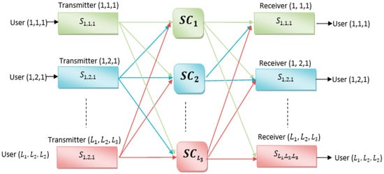
Figure 1.
3D spectral/temporal/spatial OCDMA system.
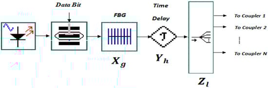
Figure 2.
Proposed Spectral/Temporal/Spatial OCDMA Transmitter Architecture.
First, the binary data are generated with help from the PRBS generator, which outputs the data in the form of an electrical signal. These data are delivered to the EOM, which modulates it depending on the ON-OFF keying (OOK) format and converts it from an electrical form to an optical form. Second, the FBG receives the modulated optical pulses from the EOM and encodes them spectrally in accordance with the wavelength corresponding to ‘’ of the code sequence; meanwhile, the other wavelengths, which do not correspond to ‘’ of the code sequence, are removed and filtered out.
After that, these optical and encoded pulses are reflected to compensate for the run-trip delay, and they are then delivered to the delay line, which aims to encode them temporally in accordance with the moment corresponding to ‘’ of the code sequence. The output of the delay line is delivered to the specified SC, i.e., the SC corresponding to ‘’ of the code sequence to perform the spatial encoding. Thus, the three-dimensional encodings for the optical signal are complete.
The receiver structure of each user is shown in Figure 3. It presents the operation opposite to that of the transmitting structure, and it is composed of a power combiner (PC), a delay line, a single FBG, low-pass filter, and a single PIN-photodiode (PIN-PD), because the spectral direct detection (SDD) technique is being applied.
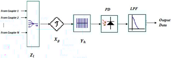
Figure 3.
Proposed Spectral/Temporal/Tpatial OCDMA rReceiver Architecture.
The combiners work to sum the incoming signals from the SCs in accordance with the corresponding code sequence to decode the signals spatially. Then, they are transmitted to the delay line to decode them temporally, in accordance with the corresponding moment of the code sequence.
Finally, the delay line output is sent to the FBG to decode the data spectrally; it reflects back the components of spectral code sequence that correspond to ‘’. Additionally, the reflection helps to compensate for the run-trip delay. Lastly, the PD detects the reflection and converts the optical and decoded signal into an electrical signal, and the low pass filter (LPF) filters it.
4. 3D-SWZCC System Performance
In order to simplify the system analysis, four assumptions should be taken into account [29].
First, the broadband light source is ideally unpolarized, and its spectrum belongs to the interval inthe domain. ‘f0’ and ‘∆f’, are, respectively, the central optical frequency and the optical source bandwidth, and they are estimated in Hertz. Second, each spectral component received by a user has the same power. Third, each spectral component produced by the spectral encoders has identical spectral width. Finally, the fourth assumption is represented by each bitstream from each user being synchronized. Depending on these assumptions and the Gaussian approximation, the bit error rate (BER) estimation can be realized by considering the thermal noise, PIIN, and shot noise.
The photo-current noise is given by [30]:
where is Boltzmann’s constant; is the absolute temperature; is the electrical bandwidth; is the load resistance; is the average photo-current; is the coherence time; and is the electron charge.
The coherence time can be expressed as [8]:
where represents the power spectral density (PSD) for each user. It can be expressed as [8]:
where and represent the effective source power at the receiver and the data bit of the user, which may be (0) or (1), respectively.
The function can be defined as [8]:
where represents the unit step function, defined as
The output photodiode current in the receiver can be written as [8]:
where ℜ represents the photodiode responsivity and is equal to , where , , and are the quantum efficiency, Plank’s constant, and the central frequency of the original broadband optical pulse, respectively. Note that and , so Equation (18) can be written as:
The PIIN variance current can be defined as [8]:
Based on the results in Equations (19) and (20) and taking into account that the probabilities of transmitting (0) and (1) are the same, Equation (13) will become:
The average signal-to-noise ratio (SNR) can be written as [31]:
Using the Gaussian approximation, the BER is given by [31]:
The Q-factor can be derived from the BER, it can be expressed as [31]
5. Numerical Results
This section considers the performance of a system employing a three-dimensional single weight zero cross-correlation (3D-SWZCC) code using two terms: the bit error rate (BER), in terms of the number of concurrent users, amount of received power, data bit rate, optical bandwidth, and the quality factor (Q), in terms of the number of concurrent users, with the assistance of MATLAB software.
After running MATLAB software, in the workspace window, the mathematical equations obtained in terms of SNR, BER, and Q are rewriter as clear in Section 4 as a function of various parameters.
First, the parameters shown in Table 3 are typed in the variable declaration section.
Table 3.
Parameters Used for Numerical Analysis.
We set the data bit rate , the PD sensitivity , the Optical bandwidth , the effective source power , the load resistor at receiver , the receiver noise temperature , the electron charge c, and the Boltzmann constant .
Second, the equations for BER, SNR, and Q are written as calculated previously.
Due to the numerical simulation being based on the concept of comparison, each code including 3D-PD, 3D-PD/MD, 3D-DCS/MD, 3D-MD, and 3D-PTZCC is generated by writing its own mathematical formulas as mentioned above.
All the instructions of each code are signified differently from the other codes in order to avoid similarities during calculation.
Third, by using the recognized drawing commands, such as “plot”, “semilogy”, etc., and the figure definition commands, such as legend, “xlabel”, “ylabel”, etc., all the codes are grouped in a single figure in order to guarantee a fair evaluation between the codes according to the factor to be measured (BER, SNR, Q, … etc.) by varying one of the parameters, such as number of users, spectral width, effective source power, …etc., as shown in the following figures.
This section mentions the effects of moving from two-dimensional (2D) to 3D SWZCC code. Further, the code is compared with 3D-perfect difference (3D-PD), 3D-hybrid perfect difference/multi-diagonal (3D-PD/MD), 3D-hybrid dynamic cyclic shift/MD (3D-DCS/MD), and 3D-Pascal’s triangle ZCC (PTZCC) codes [1,22,23,24] for the same spectral, temporal, and spatial code lengths, which are (= 7), (= 13) and (= 3), respectively. The parameters applied for numerical analysis are listed in Table 3.
Figure 4 shows the BER alteration as a function of the number of simultaneous users for set parameters, such as a received power of −10 dBm and a data rate of 1 Gbps. As shown, our proposed code can accommodate a greater number of users, up to 454, while the 1D and 2D cases can accommodate just 68 and 157 users, respectively. As a result, the system cardinality has been optimized by about 6.67 and 2.89 times from transitioning from 1D to 3D and from 2D to 3D, respectively. Additionally, the OCDMA system based on the 3D-SWZCC code has outperformed the 3D-PD, 3D-PD/MD, 3D-DCS/MD, and 3D-PTZCC codes, for the same code lengths, by about 4.24, 3.72, 3.22, and 1.32 times, respectively, where the system cardinality for each code is 107, 122, 141, and 354 users, respectively. This means that the system can potentially meet the demands of optical networks.
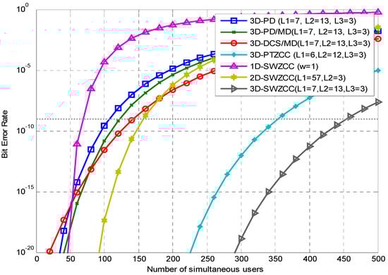
Figure 4.
BER versus the number of simultaneous users for , , and .
Figure 5 shows the SNR alteration as a function of the number of simultaneous users when the electrical bandwidth and effective source power are set to 6.5 GHz and −10 dBm, respectively. It is clear that our proposed code, 3D-SWZCC, has a greater SNR because of the high output current resulting from the photodiode (SDD technique) compared with dark current noise. Additionally, in view of the inverse relevance between the SNR and dark current, this contributes to increasing the SNR value.
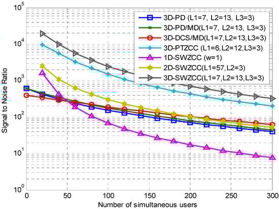
Figure 5.
SNR versus number of simultaneous users for , , and .
For K < 50, the curves of the codes that belong to ZCC families (1D, 2D, 3D-SWZCC, and 3D-MD codes) [3,15,25] have greater SNR values than the others. Beginning from K < 50, the SNR of the 1D-SWZCC code decreases rapidly; meanwhile, the SNR of the 2D-SWZCC code keeps outperforming the SNRs of the other codes until K ≥ 200, where its values become less than the SNR of the 3D-DCS/MD code.
Overall, the SNRs of the 3D codes PD, PD/MD, and DCS/MD are almost close, and the differences between them can be described by a constant along with the studied number of users. Finally, both 3D ZCC codes, SWZCC and MD, produce greater SNRs compared to other codes, but the dominant code is always our proposed code. This can be seen from the SNR values at K = 150, which were 30.79, 1.63.2, 1191, 99.97, 141.1, 136.9, and 773 for the 1D, 2D, and 3D SWZCC codes and the PD, PD/MD, DCS/MD, and PTZCC codes, respectively.
Figure 6 shows the BER alteration as a function of the data rate for 200 active users. As discussed, the system attained the required BER for optical communication networks: BERs of 4.8, 3, 0.72, 0.56, and 0.51 Gbps were obtained for the 3D codes SWZCC, PTZCC, DCS/MD, PD/MD, and PD, respectively. Consequently, employing our proposed code in an OCDMA system can supply a great data rate, nearly 5 Gbps, while other codes cannot reach 1 Gbps, with the exception of the 3D-MD code. This optimization can be explained by the ZCC property of our code, which positively and effectively optimizes the OCDMA system performance. Additionally, the 1D and 2D SWZCC codes enable each user in the OCDMA system to exploit up to 0.12 and 0.67 Gbps, respectively. Note that the differences between 1D and 3D and 2D and 3D in terms of the allowable data rate amount to approximately 40 and 7.1 times, respectively.
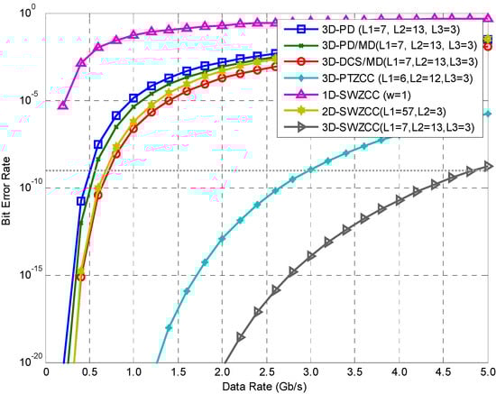
Figure 6.
BER versus data rate for K = 200.
Figure 7 displays the BER alteration as a function of the received power for 150 active users and a data rate of 1 Gbps. For dBm, all codes have roughly the same performance; in other words, all OCDMA systems tested in this investigation are the same in terms of the BER, referring to the restriction case for curves. On the other side, the curves of the 3D-PD and 3D-PD/MD codes and even the 3D-DCS/MD code vary speedily from dBm, and they do not have the ability to achieve the BER floor due to the intense influence of PIIN. Nonetheless, the latter can achieve the BER floor, but with difficulty, at dBm. Regarding the other codes, they start in variation until the BER floor is achieved at −6.6, −10.3, −14.9, and−13.8 dBm for the 1D, 2D, 3D SWZCC, and 3D-MD codes, respectively. In accordance with the above outcomes, employing our proposed code enables each user in the OCDMA system to require only minor power at the receiver level and saves around −9.1 and −1.1 dBm compared with the 3D-DCS/MD and 3D-MD codes [24,25], respectively. In addition, the transitions from 1D to 3D and from 2D to 3D save around −8.3 and −4.6 dBm, respectively.
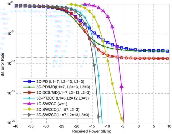
Figure 7.
BER versus effective source power for K= 150.
The fifth parameter to be discussed in this investigation is the BER alteration, which is shown as a function of the optical bandwidth for 100 active users in Figure 8. It is plain that the 1D-SWZCC curve is not drawn, since its ZCC feature and its SNR expression do not include the ‘∆f’ symbol. For the BER threshold, our proposed code can satisfy optical communication needs with an optical bandwidth of 0.03 THz, while the 3D-PD, 3D-PD/MD, 3D-DCS/MD, 3D-PTZCC, and 2D-SWZCC codes [1,3,22,23,24] force the OCDMA system to access optical bandwidths of 4.6, 4, 3.7, 0.07, and 1.68 THz, respectively. Employing the 3D-SWZCC code enables the OCDMA system to decrease its use of the bandwidth of the light source by 4.75, 3.97, 3.67, and 0.04 THz compared with the 3D-codes PD, PD/MD, DCS/MD, and PTZCC, respectively; additionally, 1.65 THz of bandwidth is saved by moving from 2D to 3D.
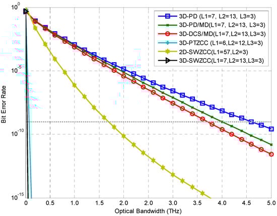
Figure 8.
BER versus optical bandwidth for K = 100.
Figure 9 highlights the effect of each noise source on the QoS of our system for the electrical and optical bandwidths at 6.5 MHz and 5 THz, respectively. When we take into account the effects of all noise sources, the SNR is diminished and is almost the same for PIIN and thermal noise, with a constant difference that is the shot noise value, as shown by the blue and green curves. Additionally, when we ignore the effect of PIIN, the SNR also diminishes: it gives average values that are between those given by the PIIN and thermal noise curve (green curve) and the curve representing all noise sources (blue curve), as shown by the magenta curve when the number of users is greater than 50. The latter case takes into account both PIIN and shot noise while ignoring the thermal noise; in this case, the SNR will greatly increase, as shown by the red curve. Briefly, we have two cases that have approximately the same results. From this, we can deduce that the OCDMA system is most affected by thermal noise. Further, one can neglect PIIN as well; the SNR is most affected by thermal noise and is not affected much by shot noise. The above result, which demonstrates the low effect of PIIN, comes from the zero cross-correlation feature of our proposed code. These results have been discussed based on the dB values of the SNR as a function of the number of simultaneous users.
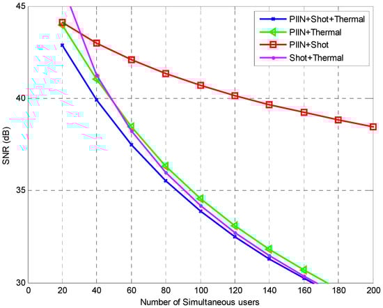
Figure 9.
SNR versus number of simultaneous users for different noise sources.
Using Equation (24), the Q-factor alteration as a function of the number of simultaneous users is plotted for a data rate of 1000 Mbps, as depicted in Figure 10. When the number of users increases, the Q- factor decreases, which demonstrates the negative correlation between them, in contrast to BER and ‘K’. At an agreeable Q-factor value for optical communication, which is given by 6 dB, the OCDMA system cardinality is 454, 354, 157, 141, 122, 107, and 68 for the 3D-SWZCC, 3D-MD, 2D-SWZCC, 3D-DCS/MD, 3D-PD/MD, 3D-PD, and 1D-SWZCC codes, respectively [3,15,22,23,24,25]. From this, it is clear that the results shown in Figure 10 match the results shown in Figure 4. Therefore, we can say that it is possible to utilize Q-factor or BER criteria to estimate the system performance. On the other side, the total code length of the 3D-SWZCC code amounts to 273 for , and , with K = 454.
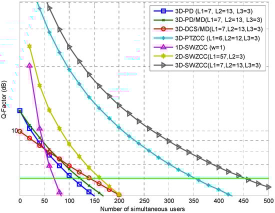
Figure 10.
Q-factor versus number of simultaneous users.
Moreover, the total code length of the 1D-SWZCC code sequence amounts to L = K = 68; meanwhile, the total code length of the 2D SWZCC code sequence amounts to L = 171 for and 3 with K = 157. We observe that the progress has been made in terms of the system capacity, in reducing the code length as well.
Nonetheless, the effective cardinality (η) of our proposed code can be computed based on the expression in Equation (25) below:
From this, we calculate the effective cardinalities of 166, 126, 91, 52, 44, 37, and 100% for the 3D-SWZCC, 3D-MD, 2D-SWZCC, 3D-DCS/MD, 3D-PD/MD, 3D-PD, and 1D-SWZCC codes, respectively.
The results above demonstrate that the 3D-SWZCC code is capable of outperforming the other codes tested in this investigation, making it more flexible and convenient for meeting optical communication demands and being used in an NG-3D-OCDMA-PON network.
Finally, the alteration of the PIIN as a function of the received power is shown in Figure 11 for 150 active users. First, note that the relationship between the PIIN and received power is linear. Second, both the 3D-PD and 3D-PD/MD codes have the same PIIN alteration, whereas the 3D-DCS/MD code has less power. Third, the 3D-PTZCC and 3D-SWZCC codes have similar values with a low difference between them. However, we find that the 3D-OCDMA system based on the 3D-SWZCC code is the least influenced by PIIN compared to the other codes. To confirm this, the values of the PIIN at = −25 dBm are , , , and A for the 3D codes SWZCC, PTZCC, DCS/MD, PD, and PD/MD, respectively [1,22,23,24].
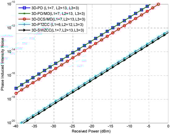
Figure 11.
PIIN versus received power.
PD output current and dark current noise alteration as a function of received power as shown in Figure 12 and Figure 13, respectively. It is observed that the variation of output PD current with an effective source power of 3D-SWZCC code is smallest compared with 3D codes: PD, hybrid PD/MD, and DCS/MD whereas the 3D-PTZCC code is less than our proposed code. This is due to these codes using the AND detection technique at the receiver level, whereas our code and the 3D-PTZCC code are using the SDD detection technique. As it is known, the AND detection technique permits the implementation of a specific filter for each wavelength which increases the signal quality. However, it is enough to implement a single filter whatever the code weight in the SDD detection technique. So, the power of the signal resulting from the SDD technique is less minor than the AND technique. Moreover, the AND technique needs to use eight PDs, but the SDD technique needs just a single PD. Consequently, the SDD technique minimizes the OCDMA system complexity based on the 3D-SWZCC code up to 75% compared with the OCDMA system using the 3D codes: PD, hybrid PD/MD, and hybrid DCS/MD.
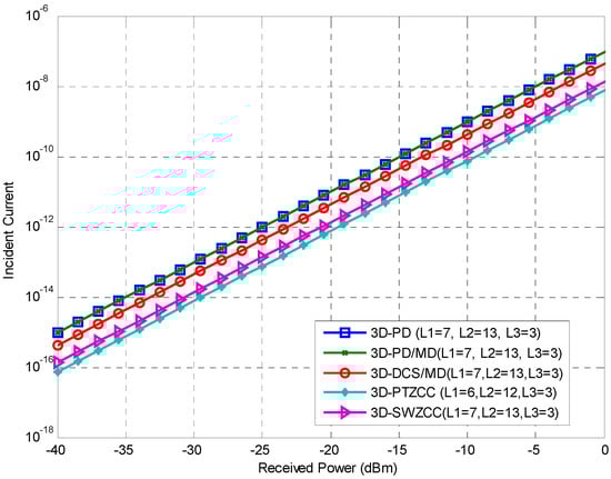
Figure 12.
Incident current versus effective source power.
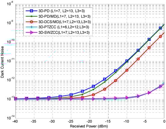
Figure 13.
Dark current noise versus effective source power.
Additionally, we are interested in studying the following parameters.
In contrast, as cleared in Figure 13, the current dark noise is a function of effective source power where it is observed that the significant effect caused by PIIN on OCDMA system uses the 3D codes: PD, hybrid PD/MD, and DCS/MD. Furthermore, these codes suffer from fixed in-phase cross-correlation in spite of the high auto correlation values. However, due to the characteristics of our code which provided a high auto correlation and zero cross-correlation, the MAI is totally suppressed, and the PIIN is reduced, which reduces the value of the dark current noise.
6. Network Setup
In this section, our proposed 3D-SWZCC code is emulated with the help of Optisystem software version 7.0. The parameters used in the mimic test are listed in Table 4.
Table 4.
System parameters used for network simulation.
6.1. Principle of 3D-OCDMA-PON
To attempt to use the 3D-SWZCC code-based OCDMA system for a PON and tackle the aforementioned problems, this section offers a novel scheme for the WTS-OCDMA system by relocating the SCs in order to diminish the power decline and extent of the fibers among the transmitter (Te) and receiver (Re) nodes. The proposed architecture is able to significantly emulate the conventional scheme of a PON while keeping the great cardinality and capacity of a 3D-SWZCC-based OCDMA system.
Although there are a lot of fibers used between OLT and ONUs, PON is employed to save the number of fibers, but this number is necessary to achieve spatial encoding as FBG and delay lines are needed to achieve the spectral and temporal encoding, respectively.
There are advantages of the proposed OCDMA-PON compared to such state-of-the-art PON technologies. The optical CDMA technique is a point-to-multipoint technology where each end-user picks up its own message from the broadcast signal. Similarly, PON architecture is also point-to-multipoint access technology with passive components, such as splitters, couplers, fiber-optics, etc., where potentially the cost is reduced.
As the amount of energy that can be consumed by an AON is more than that consumed by a PON, a PON is therefore considered overall to be an energy saver. This contributes to saving the power consumed by the OCDMA system if the OCDMA and PON have emerged in the same network.
In order to obtain results that can be described as near the practical performance of such a system, some factors should be taken into consideration, such as the non-linearity characteristics of a single-mode fiber (SMF) and noise sources, represented by the thermal noise coefficient. In accordance with the 3D-SWZCC-OCDMA system model which we propose to implement for a PON, we include six users: two users appropriated for spectral encrypting, two users appropriated for temporal encrypting, and two users appropriated for spatial encrypting, as shown in Figure 13. Thus, the total code length is equal to eight ().
As shown in Figure 14, as in other PON systems, the proposed network can be partitioned into the following two sections: an optical line terminal module (OLT) at the central office and optical network units (ONUs) at the subscriber’s premises to replicate a basic PON. In addition, Optical Distributed Network (ODN) contains a long-span light-wave path named feeder fiber that carries the three-dimensional encoded spectrum from the central office to the remote node that houses a coupler module to splits the network into a point-to-multipoint domain.
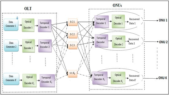
Figure 14.
3D-SWZCC/OCDMA-PON architecture.
The OLT of our proposed system contains transmitter units; in our case, there are eight units, and each one of them contains a pseudorandom bit sequence (PRBS) generator, non-return to zero (NRZ), and a white light source (WLS) that is responsible for the generation of optical bandwidth. It is bonded with a Mach–Zehnder Modulator (MZM), which functions as a signal transformer that transforms electrical signals into optical signals. Additionally, each unit contains the components specified for spectral and temporal encrypting techniques, which are FBGs and delay lines, respectively.
Thus, the upstream data generated from the OLT are divided by the star couplers (SCs), and thereafter they are accumulated by combiners to ensure the delivery of the summed signals to the ONU over SMFs.
The combiner works to convey the combined signals of different users over an SMF. For this section of the ONU, a power splitter is connected to an FBG, which in turn is connected to a delay line. The connection between the OLT and ONU sections can be achieved with the assistance of an SMF.
The modulated pulses are handed over to the spectral encoder from the MZM; in our proposed network, we utilize a single set of FBGs, since the code weight is always equal to one.
The FBG reflects a coincided wavelength to 1s of the code word. The spectrally encrypted signals are re-conveyed over a specified temporal moment with the help of delay lines. Finally, for spatial encrypting, the SCs accumulate between two different incoming data by two users who previously encrypted spectrally and timing and re-convey them into the combiner after passing them over optical switches.
After the data are received, the combined signals are divided and decrypted spectrally using the FBG and then temporally using the delay line. A single PD is placed in order to fulfill two targets: the first for the spectral direct detection (SDD) technique and the second for returning the data to its original nature (electrical signal). Finally, a low-pass Bessel filter and BER analyzer complete the remaining components for each ONU.
Table 5 elucidates how to encode and decode in three dimensions, spectral, temporal, and spatial, when there are eight users and an appropriate code word for each of them. Let us take the third user as an example: it needs an encoder or, in other words, one filter, for () spectral encoding. Later, a filter should be linked to the second delay line (). Finally, the delay line should be linked to the first SC (). Using these links, the three-dimensional encoding is obtained; it is shown in more detail in Figure 15 (system schemes). The three-dimensional decoding operation is the opposite of the encoding operation.
Table 5.
Performed code-word in our proposed system.
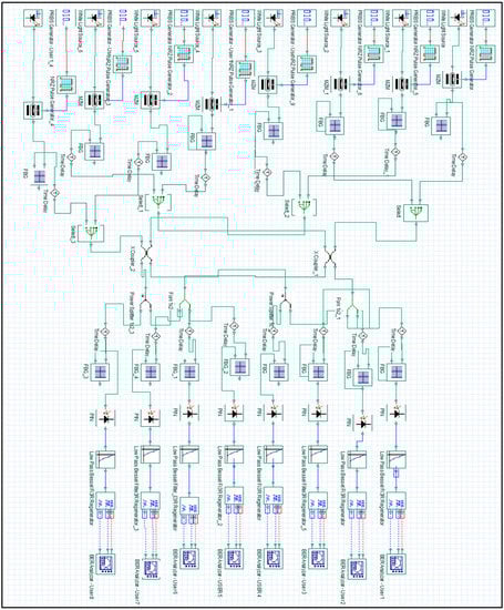
Figure 15.
Block diagram of the 3D-OCDMA system.
6.2. Simulation Results of 3D-OCDMA-PON
First, note that the eye diagrams of eight active users shown in Figure 16 are all different, and none of them are similar to each other. Moreover, the Q-factor values of the users are between 9 and 12 dB, which means that our proposed code offers good results in spite of high data rates, up to 8 Gbps. The 3D-SWZCC code has the ability to detect and restore the desired signals.
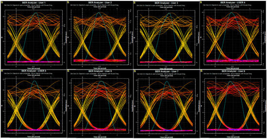
Figure 16.
Eye diagrams of the eight users at a data rate of 1 Gbps.
In accordance with the aforementioned results in Figure 14, the fact that the eye diagrams of different users are not the same means that the BER and Q-factor values are also different. These phenomena can be explained by several factors:
- Power waste: All users have equal power on the transmitter side, but during the transmission, they are subject to power losses, and this loss is not necessarily the same for all of the users.
- Synchronization absence: Each user sends its information, but it is not necessary for all users to be restricted to a given moment.
- PIIN effect: Since the power loss is different for each user, there must be varying PIIN effects, as in Equation (24), so this will be reflected by the BER. Additionally, this was demonstrated in Figure 11.
- Spectrum differential: OCDMA is considered a multi-service transmission technique. This means that it can send data in different formats, such as audio, videos, files, images, etc. Further, each format has its signal type; this means that there are various signal types carried in the same network, and each one has a distinct spectrum.
Second, the performance of the 3D-SWZCC code is also estimated at different data rates and characterized by referring to the BER and the eye diagram patterns, as shown in Figure 17. It is clear that the SWZCC code gives the 3D-OCDMA system a good performance; this can be observed through the resulting BER and Q-factor values. The BER values are , , and , and the Q-factor values are 18.84, 11.09, 8.51, and 7.05 for data rates of 0.622, 1, 1.5, and 2 Gbps, respectively.
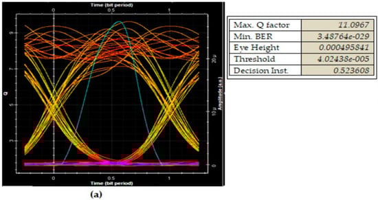
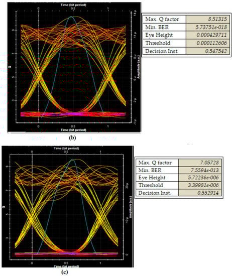
Figure 17.
(a–c). Eye diagrams of the eight users using 3D-SWZCC code at 0.622, 1, and 2 Gbps.
Consequently, we note that both the Q-factor and BER values do not override their sills (Q = 6 dB, BER = ); they should be, respectively, greater than 6 dB and less than . Additionally, the system performance can be evaluated through the opening of the eye diagram, because if it extends over a wider range, this denotes the diminishing of MAI and indicates that the system has better performance and vice versa.
Figure 18 shows the SMF length variation compared to the Q-factor. It is clear that if the length of the SMF increases, the Q-factor will be diminished, which signifies that the relationship between them is an inverse relationship. Furthermore, the optical fiber dispersion also influences the system performance. Due to the fact that each user exploits a high data rate, estimated to be 0.622, 1, 1.5, and 2 Gbps in the four different cases, it is remarkable that the SMF length of our proposed system, for acceptable BER, reaches 122, 69.2, 48.4, and 33.8 km, respectively. Similarly, it is very clear that our code satisfies the requirements of optical communication systems.
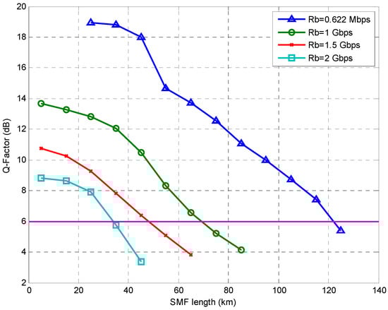
Figure 18.
Q-factor versus distance.
Finally, Figure 19 shows the Q-factor variation as a function of the data rate for fixed SMF lengths of up to 20, 30, and 40 km. It is evident that the Q-factor diminishes when the data rate is increased. This indicates the direct relationship between them. The analysis is performed for eight users accessing the milieu simultaneously. It can be seen that the performance of our proposed network lessens when the SMF length is increased. However, better performance for the 3D-SWZCC setup with = 2, = 2, and = 2 can be achieved at 10 km of distance with a provided data rate of 3.02 Gbps. Moreover, the BER increases at a distance of 30 km; in this case, the system does not perform as well until the data rate goes from 3.02 to 2.06 Gbps. Similarly, the system is impaired until a data rate of 1.45 Gbps is used at 50 km.
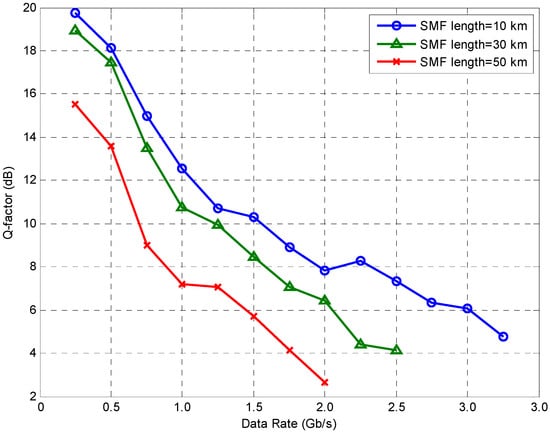
Figure 19.
Q-factor versus data rate for the SMF lengths 10, 30, and 50 km.
7. Conclusions
This paper proposes a novel code design, named 3D-SWZCC code, which uses three encoding schemes: spectral, temporal, and spatial for the first, second, and third components, respectively, with the aim of implementing the proposed code in an adapted 3D-OCDMA-PON network. The proposed code overcomes most of the obstacles, mainly the MAI effects and limited capacity, as well as the PIIN effect, which becomes lower using the developed code compared to other 3D systems that use PD, PD/MD, DCS/MD, and PTZCC codes. Additionally, the proposed 3D-SWZCC code offers good simulation results and satisfies the optical communication requirements by presenting a good quality factor of more than 6 dB and a low BER value of less than 10−9. The suggested SMF length for NG-OCDMA-PON systems can reach up to 122 Km for a data rate of 0.622 Gb/s without implementing any amplifier, which enables each user to have a high data rate with long SMF lengths like 10, 30, and 50 Km. This is achieved due to the ZCC features, which can perfectly restrict the MAI influence, making the proposed code a prospective candidate for satisfying the optical communication requirements in NG-OCDMA-PON networks.
Author Contributions
Conceptualization, A.C. and T.M.C.; methodology, A.S.K.; software, J.M.H.B.; validation, I.D; formal analysis, O.A.; investigation, A.C.; resources, T.M.C.; data duration, A.S.K.; writing—original draft preparation, I.D.; writing—review and editing. A.C.; visualization, O.A.; supervision, A.S.K.; project administration, A.C. All authors have read and agreed to the published version of the manuscript.
Funding
This research received no external funding.
Institutional Review Board Statement
Not applicable.
Informed Consent Statement
Not applicable.
Data Availability Statement
Not applicable.
Acknowledgments
This research is supported by The General Directorate of Scientific Research and Technological Development ‘DGRST’-Algeria.
Conflicts of Interest
The authors declare no conflict of interest.
References
- Cherifi, A.; Mrabet, H.; Seddik, B.; Aljunid, S.A. Performance Enhancement of Multiple Access 3D-OCDMA Networks Using a Pascal Triangle Codes. Opt. Quantum Electron. 2020, 52, 131. [Google Scholar] [CrossRef]
- Meftah, K.; Cherifi, A.; Dahani, A.; Alayedi, M.; Mrabet, H. A Performance Investigation of SAC-OCDMA System Based on a Spectral Efficient 2D Cyclic Shift Code for next Generation Passive Optical Network. Opt. Quantum Electron. 2021, 53, 569. [Google Scholar] [CrossRef]
- Cherifi, A.; Jellali, N.; Najjar, M.; Aljunid, S.A.; Bouazza, B.S. Development of a Novel Two-Dimensional-SWZCC–Code for Spectral/Spatial Optical CDMA System. Opt. Laser Technol. 2019, 109, 233–240. [Google Scholar] [CrossRef]
- Mrabet, H.; Cherifi, A.; Raddo, T.; Dayoub, I.; Haxha, S. A Comparative Study of Asynchronous and Synchronous OCDMA Systems. IEEE Syst. J. 2021, 15, 3642–3653. [Google Scholar] [CrossRef]
- Alayedi, M.; Cherifi, A.; Ferhat Hamida, A.; Bouazza, B.S.; Rashidi, C.B.M. Performance Enhancement of SAC-OCDMA System Using an Identity Row Shifting Matrix Code. In Proceedings of the international Conference on Information Technology and Applications (ICITA), Dubai, United Arab Emirates, 21 April 2022. [Google Scholar]
- Rahmani, M.; Cherifi, A.; Sabri, G.N.; Bouazza, B.S.; Karar, A. Contribution of OFDM Modulation to Improve the Performance of Non-Coherent OCDMA System Based on a New Variable Weight Zero Cross Correlation Code. Opt. Quant. Electron. 2022, 54, 576. [Google Scholar] [CrossRef]
- Alayedi, M.; Cherifi, A.; Hamida, A.F. Performance Enhancement of SAC-OCDMA System Using a New Optical Code. In Proceedings of the 2019 6th International Conference on Image and Signal Processing and their Applications, University of Mostaganem, Mostaganem, Algeria, 24–25 November 2019; pp. 1–4. [Google Scholar]
- Rahmani, M.; Cherifi, A.; Karar, A.S.; Naima Sabri, G.; Bouazza, B.S. Contribution of New Three-Dimensional Code Based on the VWZCC Code Extension in Eliminating Multiple Access Interference in Optical CDMA Networks. Photonics 2022, 9, 310. [Google Scholar] [CrossRef]
- Tseng, S.P. A New Polarization-SAC Scheme Suitable for Compact OCDMA-FSO Networks. IEEE Syst. J. 2019, 13, 1333–1335. [Google Scholar] [CrossRef]
- Butt, R.A.; Waqar Ashraf, M.; Faheem, M.; Idrus, S.M. Processing Efficient Frame Structure for Passive Optical Network (PON). Opt. Switch. Netw. 2018, 30, 85–92. [Google Scholar] [CrossRef]
- Cen, M.; Chen, J.; Moeyaert, V.; Megret, P.; Wuilpart, M. Advanced Transmission-Reflection-Analysis (TRA) System for Long-Reach Passive Optical Network Monitoring. In Proceedings of the 2015 17th International Conference on Transparent Optical Networks (ICTON), Budapest, Hungary, 5–9 July 2015; pp. 2–5. [Google Scholar] [CrossRef]
- Kora, A.D.; Diouf, M.D.; Ouya, S.; Cances, J.P. Fundamenal Limitations on Introducing Low Cost Optical Sources in Hybrid 40/100G PON. In Proceedings of the13th International Conference on Advanced Communication Technology (ICACT2011), Gangwon, Republic of Korea, 13–16 February 2011; pp. 369–372. [Google Scholar]
- Aldaya, I.; Giacoumidis, E.; de Oliveira, G.; Wei, J.; Pita, J.L.; Marconi, J.D.; Fagotto, E.A.M.; Barry, L.; Abbade, M.L.F. Histogram Based Clustering for Nonlinear Compensation in Long Reach Coherent Passive Optical Networks. Appl. Sci. 2020, 10, 152. [Google Scholar] [CrossRef]
- Mohammed, N.A.; Mansi, A.H. Performance Enhancement and Capacity Enlargement for a DWDM-PON System Utilizing an Optimized Cross Seeding Rayleigh Backscattering Design. Appl. Sci. 2019, 9, 4520. [Google Scholar] [CrossRef]
- Alayedi, M.; Cherifi, A.; Ferhat Hamida, A.; Bouazza, B.S.; Aljunid, S.A. Improvement of Multi Access OCDMA System Performance Based on Three Dimensional-Single Weight Zero Cross Correlation Code. In Proceedings of the 2021 3rd International Conference on Computer and Information Sciences ICCIS 2021, Sakaka/Aljouf, Saudi Arabia, 19–21 October 2021. [Google Scholar]
- Kadhim, R.A.; Fadhil, H.A.; Aljunid, S.A.; Razalli, M.S. A New Two Dimensional Spectral/Spatial Multi-Diagonal Code for Noncoherent Optical Code Division Multiple Access (OCDMA) Systems. Opt. Commun. 2014, 329, 28–33. [Google Scholar] [CrossRef]
- Morsy, M.A. Analysis and Design of Weighted MPC in Incoherent Synchronous OCDMA Network. Opt. Quantum Electron. 2018, 50, 387. [Google Scholar] [CrossRef]
- Yousif Ahmed, H.; Nisar, K.S. Diagonal Eigenvalue Unity (DEU) Code for Spectral Amplitude Coding-Optical Code Division Multiple Access. Opt. Fiber Technol. 2013, 19, 335–347. [Google Scholar] [CrossRef]
- Abd, T.H.; Aljunid, S.A.; Fadhil, H.A.; Ahmad, R.A.; Saad, N.M. Development of a New Code Family Based on SAC-OCDMA System with Large Cardinality for OCDMA Network. Opt. Fiber Technol. 2011, 17, 273–280. [Google Scholar] [CrossRef]
- Malleswari, M.; Murugesan, K. Construction and Bit Error Analysis of Zero Cross-Correlation Codes for SAC-Optical CDMA Systems. J. Opt. 2013, 42, 307–310. [Google Scholar] [CrossRef]
- Yeh, B.; Lin, C.; Wu, J.; Fellow, L. Noncoherent Spectral/Time/Spatial Optical CDMA System Using 3-D Perfect Difference Codes. J. Light. Technol. 2009, 27, 744–759. [Google Scholar] [CrossRef]
- Kadhim, R.A.; Fadhil, H.A.; Aljunid, S.A.; Razalli, M.S. Performance Enhancement of a Three Dimensional OCDMA Systems Based on A New Code. J. Theor. Appl. Inf. Technol. 2015, 81, 589–599. [Google Scholar]
- Jellali, N.; Najjar, M.; Ferchichi, M.; Janyani, V. Performance Enhancement of the 3D OCDMA System by Using Dynamic Cyclic Shift and Multi-Diagonal Codes. Photonic Netw. Commun. 2019, 37, 63–74. [Google Scholar] [CrossRef]
- Yin, H.; Richardson, D.J. Optical Code Division Multiple Access Communication Networks: Theory and Applications; Springer: Berlin/Heidelberg, Germany, 2009; ISBN 9783540684459. [Google Scholar]
- Jellali, N.; Najjar, M.; Ferchichi, M.; Rezig, H. Three-Dimensional Multi-Diagonal Codes for OCDMA System. Opt.-Int. J. Light Electron Opt. 2017, 145, 428–435. [Google Scholar] [CrossRef]
- Yen, C.T.; Chen, C.M. A Study of Three-Dimensional Optical Code-Division Multiple-Access for Optical Fiber Sensor Networks. Comput. Electr. Eng. 2016, 49, 136–145. [Google Scholar] [CrossRef]
- Yen, C.T.; Chen, C.M. BER Analysis Using Beat Probability Method of 3D Optical CDMA Networks with Double Balanced Detection. Math. Probl. Eng. 2015, 2015, 1–6. [Google Scholar] [CrossRef]
- Alayedi, M.; Cherifi, A.; Ferhat Hamida, A.; Matem, R.; Abd El-Mottaleb, S.A. Improvement of SAC-OCDMA System Performance Based on a Novel Zero Cross Correlation Code Design. In Advances in Communication Technology, Computing and Engineering; RGN Publications: Delhi, India, 2021. [Google Scholar]
- Imtiaz, W.A.; Ahmed, H.Y.; Zeghid, M.; Sharief, Y.; Usman, M. Design and Implementation of Two-Dimensional Enhanced Multi-Diagonal Code for High Cardinality OCDMA-PON. Arab. J. Sci. Eng. 2019, 44, 7067–7084. [Google Scholar] [CrossRef]
- Mostafa, S.; Mohamed, A.E.N.A.; Abd El-Samie, F.E.; Rashed, A.N.Z. Performance Analysis of Diagonal Eigenvalue Unity (DEU) Code Using NAND Subtraction and Spectral Direct Detection Techniques and Its Use with Triple-Play-Services in SAC-OCDMA. Wirel. Pers. Commun. 2015, 85, 1831–1849. [Google Scholar] [CrossRef]
- Singh, M.; Pottoo, S.N.; Armghan, A.; Aliqab, K.; Alsharari, M.; Abd El-Mottaleb, S.A. 6G Network Architecture Using FSO-PDM/PV-OCDMA System with Weather Performance Analysis. Appl. Sci. 2022, 12, 11374. [Google Scholar] [CrossRef]
Disclaimer/Publisher’s Note: The statements, opinions and data contained in all publications are solely those of the individual author(s) and contributor(s) and not of MDPI and/or the editor(s). MDPI and/or the editor(s) disclaim responsibility for any injury to people or property resulting from any ideas, methods, instructions or products referred to in the content. |
© 2023 by the authors. Licensee MDPI, Basel, Switzerland. This article is an open access article distributed under the terms and conditions of the Creative Commons Attribution (CC BY) license (https://creativecommons.org/licenses/by/4.0/).