1. Introduction
As a green and reliable underground mining method [
1,
2], the fill mining method has gradually become the main technical method of mining because it can effectively control the deformation of the surrounding rock, reduce the impact of underground mining on the surface environment, and improve the recovery rate of resources [
3,
4]. Since Minggao proposed green mining in 2003 [
5,
6], the fill mining method has been strongly advocated, and its application in coal mining has been rapidly developed [
7]. At the same time, with the deepening of the mining depth, higher requirements for the mechanical strength of the filling body have been introduced, in order to mine underground mineral resources more safely and economically. Improving the mechanical strength of the filling body would mean it could be used as an ore column to bear the roof stress and, at the same time, could effectively control the filling cost [
8]. Therefore, the study of improving the strength of the filling body materials is crucial. In addition, the safety of the roadway is very important, the causes of roadway instability are analyzed, and support countermeasures are put forward [
9,
10,
11,
12].
At present, in order to improve the stability and reliability of the filling body in the early and late stages, many scholars have carried out research on the ratio of the water–sand cemented materials [
13,
14] and also proposed the method of adding additives to improve the strength of the filling body, whereas the mechanical properties of the filling body with a polyethylene flexible material as a reinforced material have been less studied. Tan [
15] explored the stress–strain relationship of ethylene-doped fiber concrete and revealed the influence of the polyethylene fiber on concrete. Feng et al. [
16] used flexible concrete along with the empty alley technology in the 52,605 working face transportation lane of Daliuta Well and achieved good support results. Zhu et al. [
17] used artificial intelligence models to analyze the tensile strength of modified cemented fillers incorporated with glass fibers, which promoted the application of the cementation fill coal mining technology. Shi et al. [
18] used glass fiber to reinforce the mechanical properties of a cement-based tailings cemented filling body, conducted experimental research, and found that when the fiber content was 0.5%, the compressive and tensile strength of the filling body reached the maximum. Cui et al. [
19] studied the slurry fluidity, mechanical properties, and failure mechanism of cement-based filling materials with polypropylene fiber as a reinforcing agent and concluded that the fiber incorporation amount was negatively correlated with the slurry fluidity, but the fiber incorporation amount of 0.6% improved the stability and compressive strength of the filling body. Zhang et al. [
20] studied the strength of high-water filling materials mixed with polyethylene plastics, and the high-water filling materials with the appropriate addition of PE powder had a certain application value. Yang et al. [
21] used ethylene-vinyl acetate polymer (EVA) to modify concrete filling materials and concluded that the addition of the EVA improved the plastic deformation ability and the compressive performance of the concrete. Sun et al. [
22] studied the mechanical properties of high-water materials incorporated with polypropylene fibers and concluded that the cracking effect of the polypropylene fibers improved the integrity and continuity of high-water materials. Qiao [
23] proposed to use gangue and fly ash as the main raw materials, mixed with a small amount of polypropylene fiber, to prepare foam concrete filling materials and studied the mechanical properties of the filling materials, which had a positive significance for coal mine filling. He et al. [
24,
25,
26,
27,
28] studied the properties of modified magnesium coal-based solid waste filling materials mixed with polypropylene fiber, which had important practical value for mine filling. The mechanical properties of the reinforced backfill were studied [
29,
30].
In order to improve the bearin g strength of the tailings filling body, improve the safety of mining by the fill mining method, and control the filling cost, it is proposed to use polyethylene wire as a reinforcement material to improve the bearing strength of the filling body. In this paper, the dimension, grid density, and gray–sand ratio of the polyethylene wire rope grid are used as variables to carry out the uniaxial compression test, tensile test, and shear test; compared with the traditional tailing sand filling body, the compressive strength, tensile strength, and shear strength of the grid filling material under different dimensions, grid densities, and lime–sand ratios are compared and analyzed. The failure characteristics of the grid filling bodies under different conditions are also analyzed, which provide basic data for the study of polyethylene materials as reinforced materials and also provide technical guidance for the application of grid filling bodies in engineering practice.
2. Experimental Protocol Design
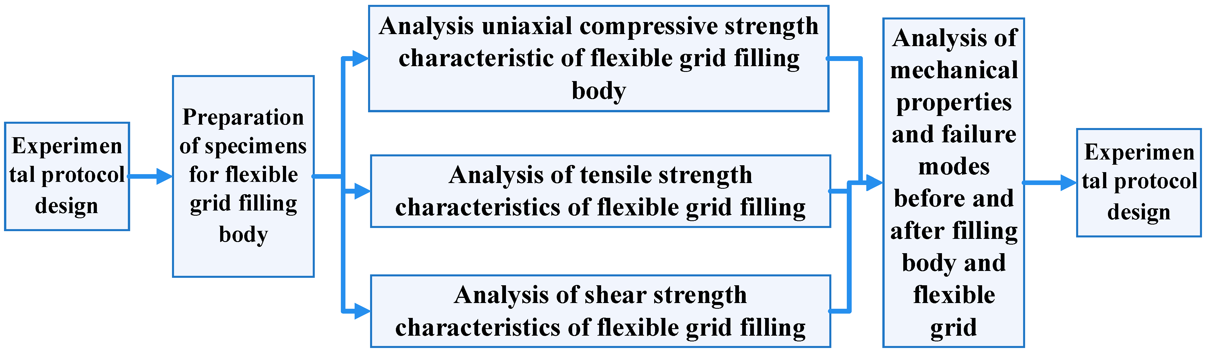
Uniaxial compressive, tensile, and shear tests were carried out on the flexible grid filling body and the ordinary filling body, the difference in the mechanical properties of the two filling bodies was analyzed, and the mechanical properties of the flexible grid filling body were obtained. The experimental flow chart is shown in
Figure 1. According to previous data, two gray–sand ratios (1:4 and 1:8), different spacings (20 mm, 30 mm, 40 mm, and 50 mm), and different dimensions (one-dimensional, two-dimensional, and three-dimensional) of the flexible grid filling body were used in the uniaxial compression, tensile, and shear tests. The specific test scheme is shown in
Table 1.
3. Flexible Grid Filling Body Specimen Preparation
- (1)
Flexible grid preparation
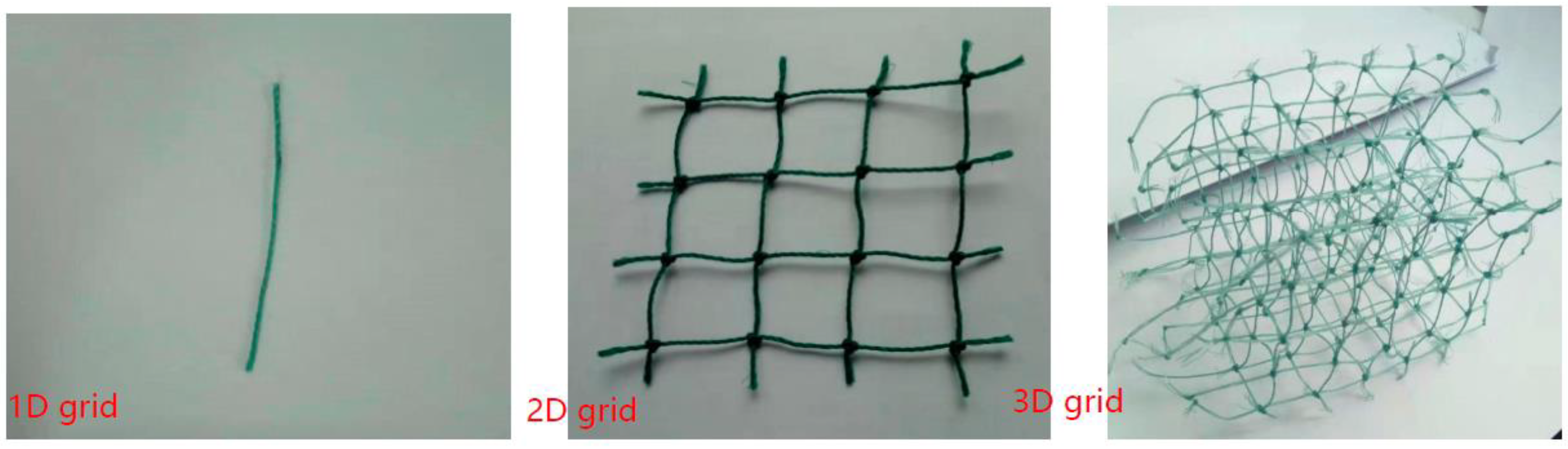
Polyethylene wire was selected as the reinforcement material; the wire diameter was 0.7 mm, the tensile force was 8 kg, the tensile strength of the single rope was 40 MPa, and the rope weight was 0.3 g/m. One-dimensional, two-dimensional, and three-dimensional grids with spacings of 20 mm, 30 mm, 40 mm, and 50 mm were made; the physical objects of the different dimensions of the polyethylene grids are shown in
Figure 2, and the number of grids in each dimension required for the preparation of the specimen is shown in
Table 2.
- (2)
Flexible grid filling body test block mold preparation
The mold used in the test was a 100 mm × 100 mm × 100 mm triple metal test mold. In total, 50 sets of test blocks were made in this test; each mold was cleaned and corrected before each mold pouring, and a thin layer of lubricating oil was brushed around the inner wall of the mold to facilitate the later demolding.
- (3)
Flexible grid filling body filling slurry configuration
The filling slurry was composed of three parts: iron ore tailings, self-produced rubber solid powder, and tap water. We prepared 280 kg tailings and a bag of 50 kg cement powder and filled the slurry according to the preformulated specimen ratio scheme for proportioning; the slurry of each specimen was as shown in
Table 3. When the ratio of the self-produced-rubber-solid–ash-sand in the mine was 1:4, 1:8, and 1:10, the strength of the filling body was equivalent to the strength of the cement–ash-sand ratio of 1:3, 1:4, and 1:8, respectively.
- (4)
Preparation of the test blocks for the flexible grid filling of different dimensions
We configured the corresponding slurry, according to the data in
Table 3 and then loaded the prepared slurry into 100 mm × 100 mm × 100 mm triple metal test molds. During the pouring process, the three-dimensional grid had good self-reliance and could be poured and formed at one time. The pouring of the one-dimensional and two-dimensional grids required the cooperation of three people (one person added the slurry, one person placed the grid, and one person observed the grid placement spacing, which could be adjusted at any time to minimize the experimental errors). The pouring process of the flexible grid filling body is shown in
Figure 2. The specific operation steps were as follows:
One-dimensional grid filling body casting mold: Several 100 mm long single lines were placed in parallel according to the different spacing requirements, shown in
Table 2, on the same horizontal plane. The number of placement strips was adjusted according to the different spacings; then, they were placed layer by layer in the vertical direction. The placement of a single line was synchronized with the slurry casting mold; that is, a layer of slurry was poured, and a layer of lines was placed. The spacing between the grille layers and layers was consistent with the single rope placement spacing.
Two-dimensional grid casting mold: The grid spacing of the different specifications was made of a flat grid with a grid spacing of 20 mm, 30 mm, 40 mm, and 50 mm. The length of the grid edge was 100 mm, and the spacing of each layer of the grid in the vertical direction of the test block was consistent with the grid spacing.
Three-dimensional grid casting mold: The three-dimensional grid was spliced from the two-dimensional grid, and the external specifications were 100 mm × 100 mm × 100 mm. The grid spacing inside the three-dimensional grid was divided into three different specifications: 30 mm, 40 mm, and 50 mm, and the schematic diagram of the pouring process of the test block of the flexible grid filling body is shown in
Figure 3.
- (5)
Demolding maintenance of the different dimensions of the flexible grid filling body test block
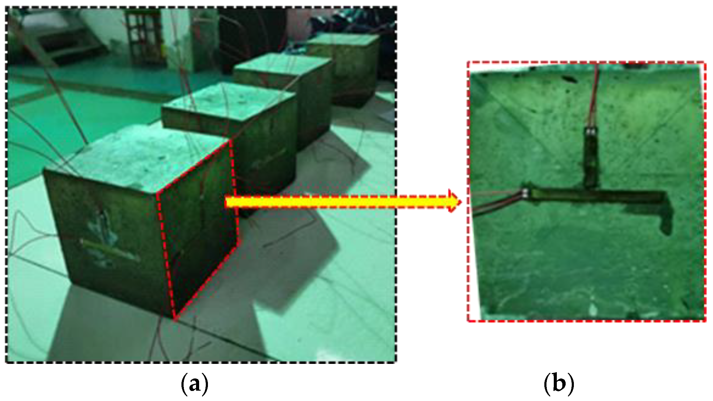
After the prepared filling slurry was poured into the trial mold, it was demolded after the final setting of the vibrating exhaust and transferred to an environment at constant temperature and humidity for maintenance; the maintenance temperature was 20 ± 2 °C, and the humidity was 95%, as shown in
Figure 4. After the test block was cured for 28 days, it was tested for the compressive, tensile, and shear strength.
4. Analysis of the Uniaxial Compressive Strength Characteristics of the Flexible Grid Filling Body
4.1. Test Equipment
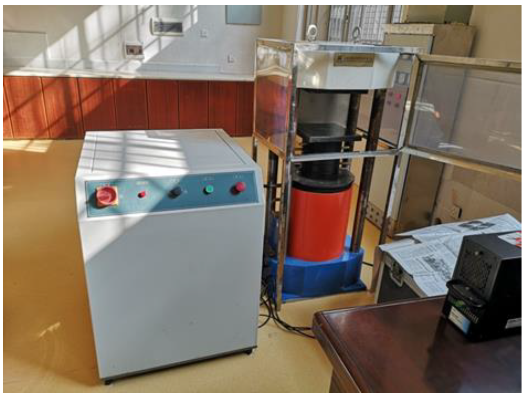
The YNS600 electrohydraulic servo universal testing machine was used for the uniaxial compression test; the maximum load of the testing machine was 600 KN, the piston stroke was 200 mm, and the speed accuracy was ±0.5%, as shown in
Figure 5.
The YNS600 electrohydraulic servo universal testing machine was used to test the uniaxial compressive strength of the specimen, and the test steps included the following:
(1) Paste strain gauges: After taking the test piece out of the maintenance site, we wiped it clean, measured the size, checked the appearance, and then pasted two vertical and horizontal strain gauges on each side of the test piece, for a total of eight. We pasted 50 compressive test pieces on the strain gauges in turn, and the schematic diagram of the test piece after some patches is shown in
Figure 6.
(2) Test: After attaching the strain gauge, the test piece was connected to the stress strain collector by a 1/4 bridge connection, and computer software was used to balance each strain gauge system after the connection (the balance ensured that the path of each line and the resistance between each line were the same).
(3) Test: We put the test block into the stress servo press for the compression test; the whole test process used a stress sensor, strain gauge, and high-definition camera to observe and record the stress and strain data and the fracture evolution law of the test piece. The uniaxial compression test layout is shown in
Figure 7.
4.2. Analysis of the Compressive Strength of the Flexible Grid Filling with Different Spacings
According to the design scheme in
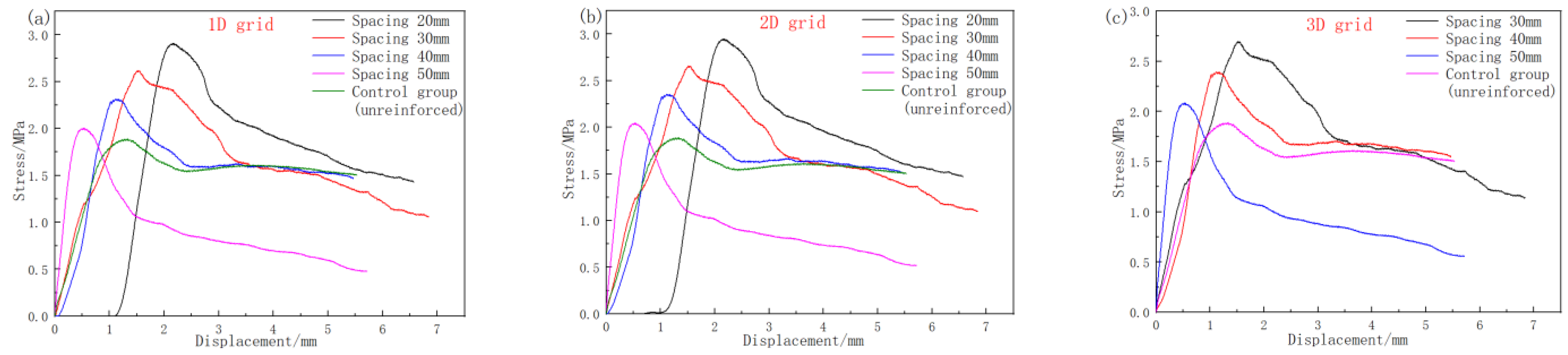
Table 3, the uniaxial compression test was carried out, and the stress–strain curves of the flexible grid filling bodies with different spacings with different ash–sand ratios (1:4 and 1:8) were plotted, according to the test results, as shown in
Figure 8 and
Figure 9.
Figure 8 and
Figure 9 show that the stress–strain curve in the uniaxial compressive test of the reinforced filling body and the unreinforced filling body was consistent, and they all went through the compaction stage, elastic stage, fracture development stage, and failure stage in turn; however, compared with the unreinforced filling body, the uniaxial compressive strength of the reinforced filling body increased, the stress peak point shifted back, the ductility increased, and the brittleness was weakened.
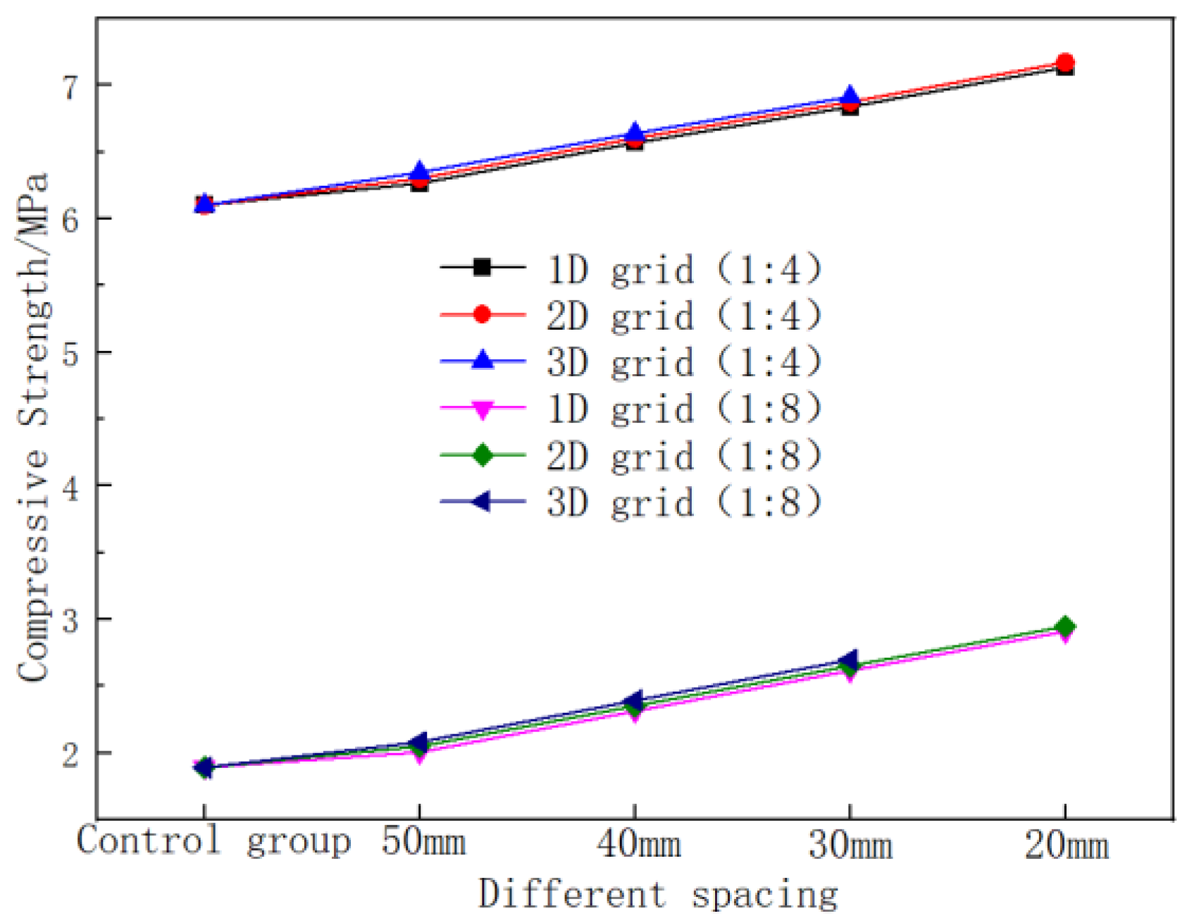
In order to further analyze the influence of the different pitch flexible grids on the compressive strength of the filling body, the uniaxial compressive strength of the filling body with different flexible grid spacings was obtained, according to the test results of
Figure 7 and
Figure 8, as shown in
Table 4 and
Figure 10.
It can be seen from
Table 4 and
Figure 9 that the uniaxial compressive strength of the flexible grid filling body gradually increased with the decrease in the grid spacing (increase of grid density), but the increase was not large; that is, for every 10 mm decrease, the uniaxial compressive strength only increased by about 5%. This shows that reducing the spacing of the flexible grid improved the uniaxial compressive strength of the filling body, but the effect was not obvious.
5. Analysis of the Tensile Strength Characteristics of the Flexible Grid Filling
5.1. Test Equipment and Process
The YNS600 electrohydraulic servo universal testing machine was used for the tensile test; the maximum load of the testing machine was 600 KN, the piston stroke was 200 mm, and the speed accuracy was ±0.5%. In addition, the tensile test also required two steel rods with a diameter of 10 mm and a length of 100 mm.
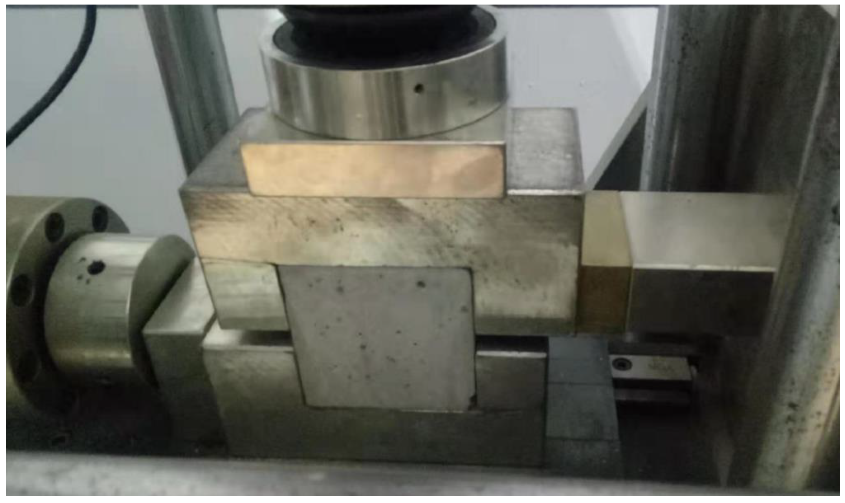
Using the YNS600 electrohydraulic servo universal testing machine to test the tensile strength of the specimen (the Brazilian splitting method), the test steps mainly included the following:
(1) Scribing: After taking the test piece out of the curing site, we wiped it clean, measured the size, checked the appearance, and drew the position line of the split surface in the middle of the test piece to ensure that the split surface was perpendicular to the top surface of the test piece when molding, and the size measurement was accurate to 1 mm;
(2) Specimen installation and test: First, the specimen was placed on the pressurized platform and geometrically centered; then, the underlay and metal rod were installed, and its orientation was perpendicular to the top surface when the specimen was formed. The placement diagram is shown in
Figure 11. Then, the test was carried out according to the test plan.
5.2. Analysis of the Tensile Strength of the Flexible Grid Filling Body with Different Spacings
The uniaxial tensile test was carried out according to the design scheme of
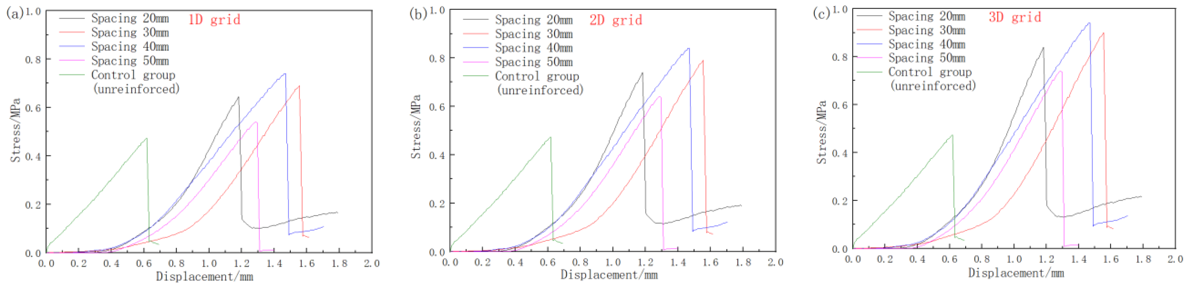
Table 1, and the test results are shown in the stress–strain curves of the flexible grid filling bodies with different ash–sand ratios (1:4 and 1:8) and different spacings, as shown in
Figure 12 and
Figure 13.
Figure 12 and
Figure 13 show that the stress–strain curve trend was consistent in the uniaxial tensile test of the reinforced filling body and the unreinforced filling body; however, compared with the unreinforced filling body, the uniaxial tensile strength of the reinforced filling body increased, the stress peak point was shifted back, the ductility was increased, and the brittleness was weakened.
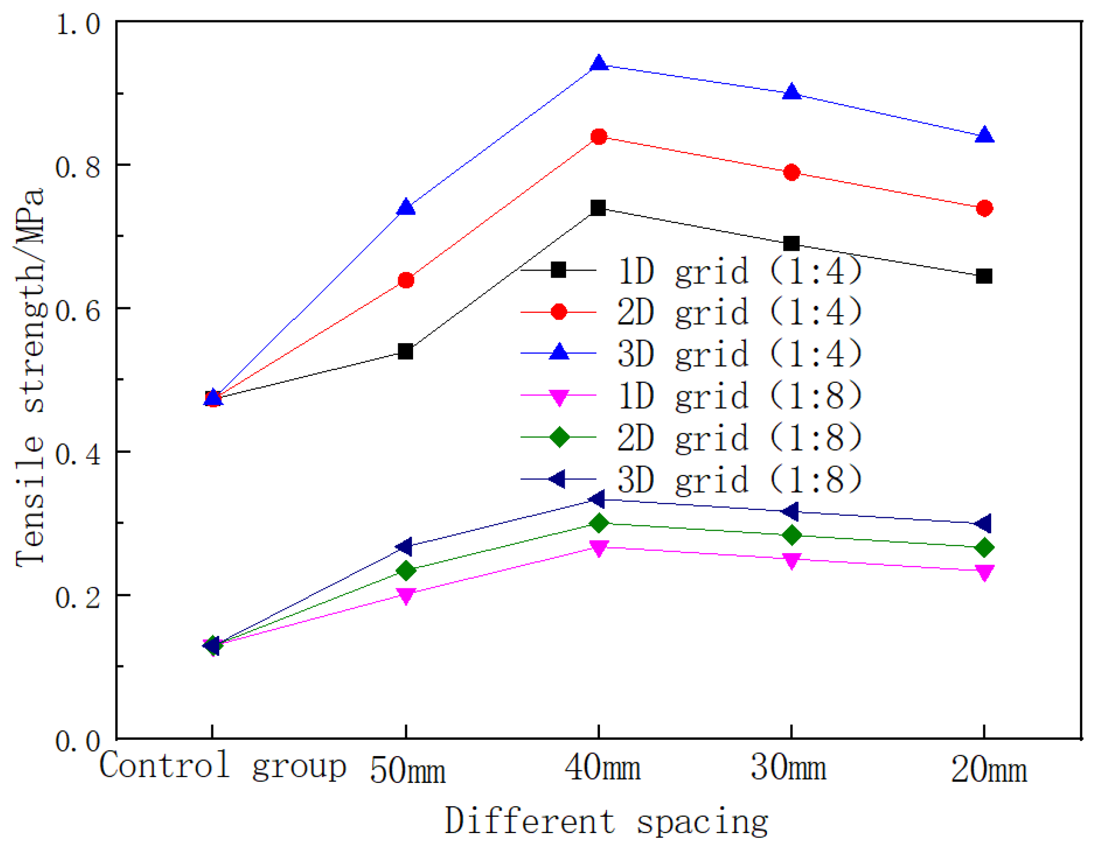
According to the test results of
Figure 12 and
Figure 13, the uniaxial tensile strength of the flexible grid filling body with different spacings is shown in
Table 5 and
Figure 14.
Table 5 and
Figure 14 show that the uniaxial tensile strength of the flexible grid filling body increased first and then decreased with the decrease in the grid spacing (increase in the grid density), and there was an optimal grid spacing of 40 mm.
6. Analysis of the Shear Strength Characteristics of the Flexible Grid Filling
In order to further analyze the overall mechanical characteristics of the flexible grid filling body with different dimensions and spacings, the shear test of the flexible grid filling body with different dimensions and spacings was carried out to obtain the shear strength, internal friction angle, and cohesion of the flexible grid filling body with different dimensions and spacings.
- (1)
Test equipment and process
The shear strength test adopted the RJST-616 multifunction shear test system; the maximum vertical loading stress of the test system was 15 MPa, the maximum horizontal loading stress was 20 MPa, the vertical and horizontal displacement ranges were 0~100 mm, the force loading rate was 0.1~1.0 kN/s, and the displacement loading rate was 0.001 mm/s~1.0 mm/s.
The shear strength of the specimen was tested by the RJST-616 multifunctional shear test system, and the test steps were as follows:
We turned on the system power, turned on the operating software, turned on the oil pump, and warmed the oil pump for 10 min.
We placed the test block into the shear mold, all plates were placed properly, and the mold was aligned with the center of the device, as shown in
Figure 15. The software interface was set to zero for both the normal and tangential forces.
The position was adjusted through the operation software to extend the normal hydraulic pump first, so that the normal shaft and the mold were in approximate contact; then, we performed the same operation, so that the tangential shaft and the mold were in approximate contact (essentially no contact). We opened a programming experiment from the history, paying attention to the modification of the normal target value. Each specimen shearing should apply an axial force in the axial direction, divided into three gradients, 2 KN, 4 KN, and 6 KN (that is, each type of test block was pressed into three pieces, and the axial pressure corresponded to the above pressure).
We started the experiment and created a different name for each experiment. When the normal preload reached 0.5 KN, we changed the normal axis holding time to 0 (the normal axis can continue to extend); when the target value of the normal force reached the preset value, we set the tangential hold time to 0 (the formal shear started at this time). When the shear strength reached the residual stage, the experiment was ended (the tangential displacement was about 6–8 cm). For the position adjustment, we retracted the normal axis and tangential axis back to the target length; we retracted the tangential axis first and then retracted the normal axis (contrary to the extension order). Then, we repeated the above steps.
- (2)
Shear strength analysis of the flexible grid filling with different spacings
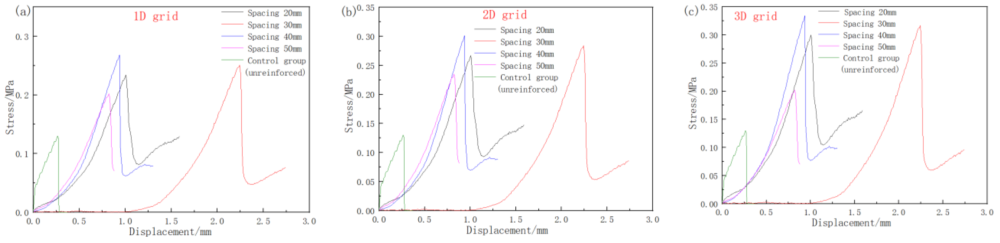
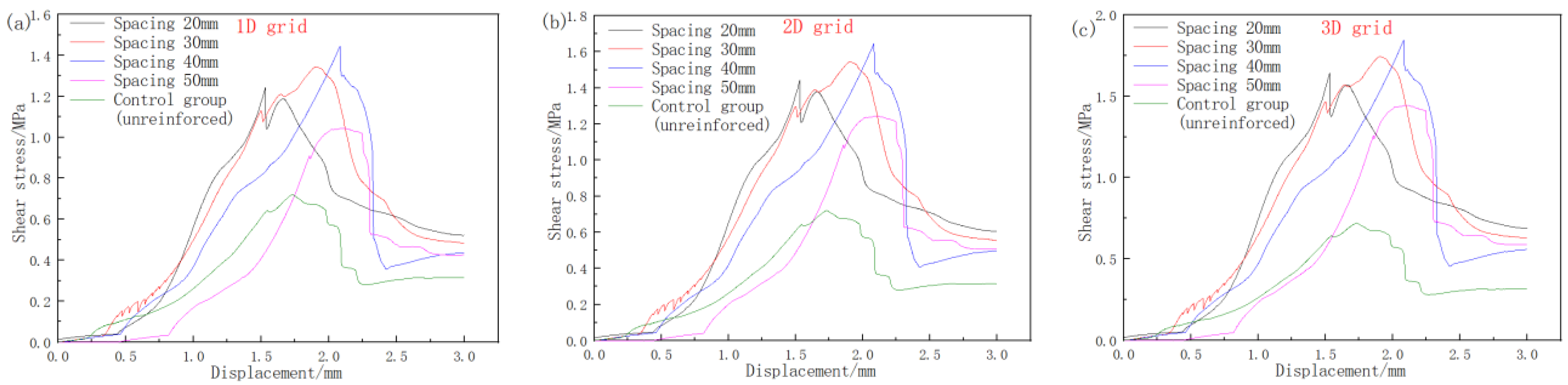
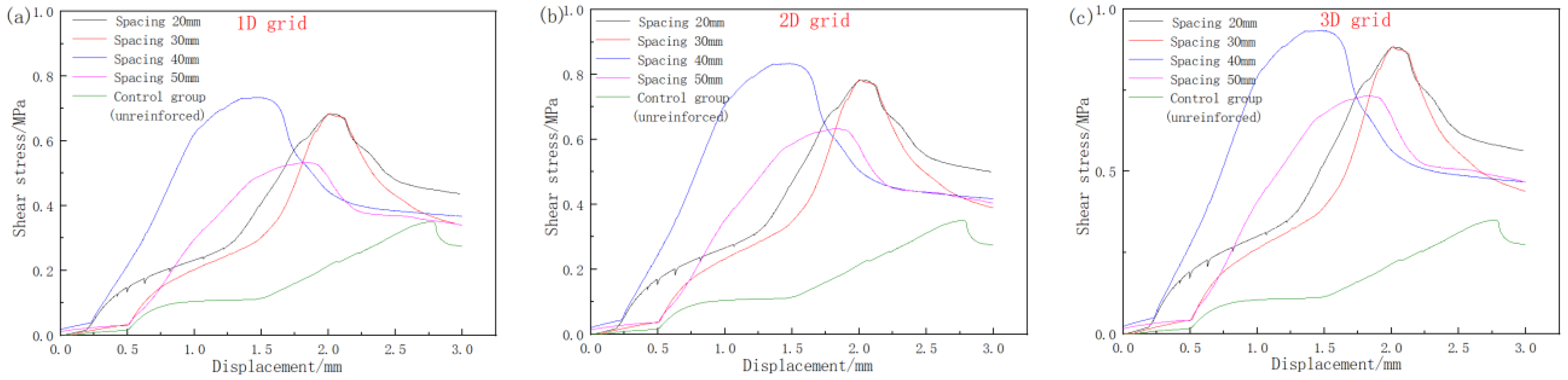
According to the design scheme of
Table 1, the shear stress–strain curves of the flexible grid filling bodies with different spacing ratios (1:4 and 1:8) were plotted according to the test results, as shown in
Figure 16 and
Figure 17.
Figure 16 and
Figure 17 show that the shear stress–strain curve of the reinforced filling body and the unreinforced filling body were consistent in the shear test, but the shear strength and brittleness of the reinforced filling body were increased, and the brittleness was weakened, compared with the unreinforced filling body.
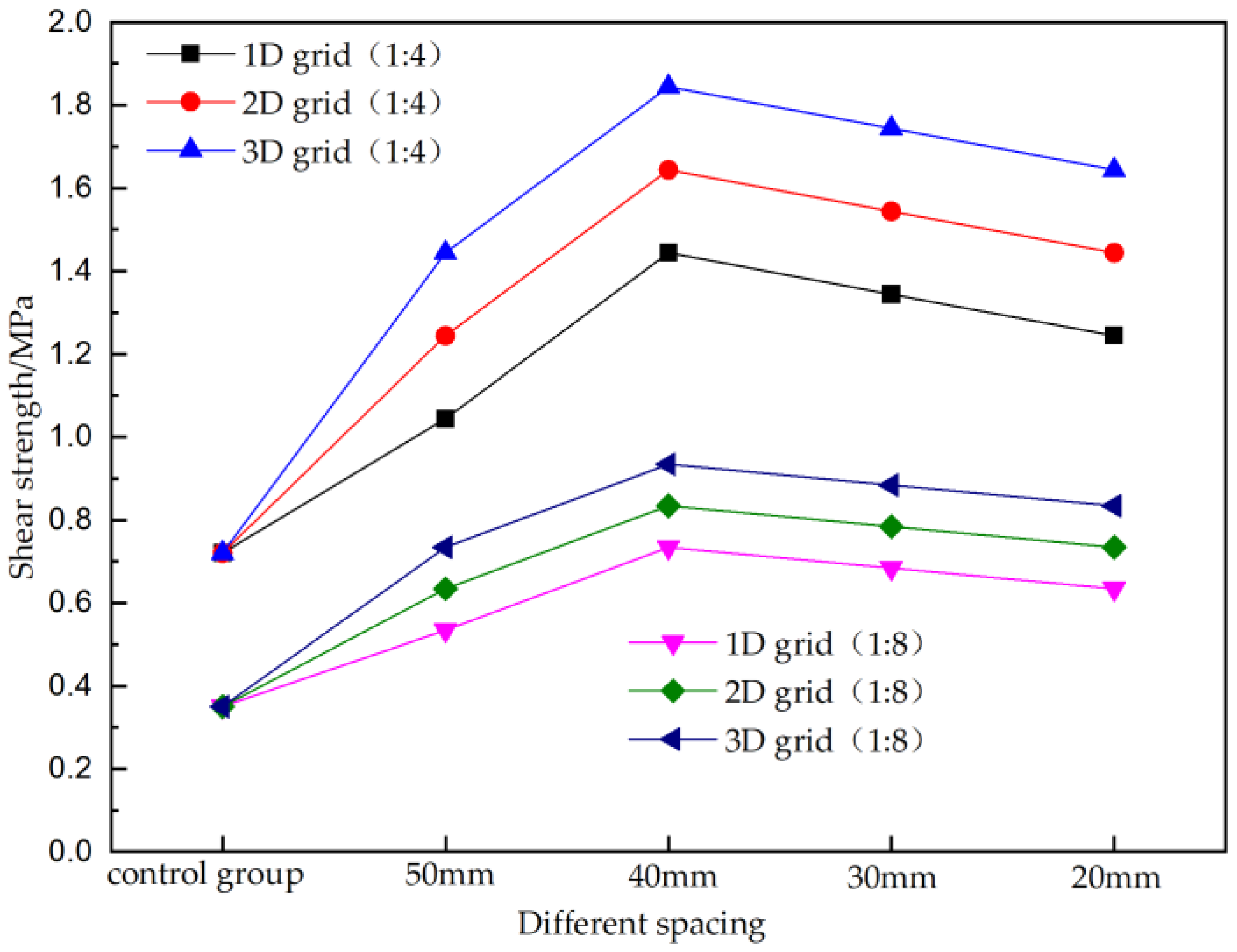
In order to further analyze the influence of the different pitch flexible grids on the tensile strength of the filler, the shear strength of the filling of the flexible grid with different spacings was obtained, according to the test results of
Figure 16 and
Figure 17, as shown in
Table 6 and
Figure 18.
It can be seen from
Table 6 and
Figure 18 that the shear strength of the flexible grid filling body first increased and then decreased with the decrease in the grid spacing (the increase in the grid density), and there was an optimal grid spacing for this test of 40 mm. The shear strength of the flexible grid filling increased with the increase in the grid dimension; that is, the shear strength of the one-dimensional grid < the two-dimensional grid < the three-dimensional grid.
7. Analysis of the Mechanical Properties and Failure Modes of the Filling Body before and after Adding the Flexible Grid
- (1)
Analysis of the mechanical properties of the filling body before and after adding the flexible grid
The previous test showed that the mechanical properties of the flexible grid were greatly improved after adding the flexible grid in the filling body. In order to quantitatively measure the strengthening effect after adding the flexible grid in the filling body, the concept of the elastic modulus, strength, cohesion, and internal friction angle strengthening coefficient
ξ of the flexible grid filling body was introduced, which is the ratio of the corresponding parameter value of the flexible grid filling body to the corresponding parameter value of the flexible grid filling body (ordinary filling body) without the addition of flexible grid filling. When
ξ < 1, the flexible grid has a weakening effect on the strength and mechanical properties of the filling body. When
ξ = 1, the flexible grid has no effect on the mechanical properties of the filling body. When
ξ > 1, the flexible grid has a strengthening effect on the filling body mechanics. The calculation formulas are as follows:
In the formula, is the tensile strength strengthening coefficient; is the shear strength strengthening coefficient; is the elastic modulus strengthening coefficient; is the cohesion strengthening coefficient; is the internal friction angle strengthening coefficient.
In the substitution into Formula (1) of the various test data of the previous gray–sand ratio of 1:4, the values of
,
,
,
, and
were calculated as shown in
Table 7.
It can be seen from
Table 7 that the values of
,
,
,
, and
were greater than 1, indicating that the mechanical properties of the flexible grid were strengthened after the addition of the flexible grid in the filling body, and its tensile strength, shear strength, elastic modulus, cohesion, and internal friction angle were increased. However, the increased amplitude was different, and the tensile strength, shear strength, cohesion, and internal friction angle strengthening coefficient of the flexible grid filling body in different dimensions were greater than its elastic modulus strengthening coefficient, indicating that the tensile and shear strength of the filling body was greatly increased after adding the flexible grid to the filling body, whereas the increase in the compressive strength was relatively small. That is, the flexible grid mainly improved the tensile and shear strength of the filling body and prevented its brittle failure, thereby increasing its toughness, ductility, and crack resistance to better meet the engineering production.
- (2)
Surface failure characteristics during the flexible grid filling body test
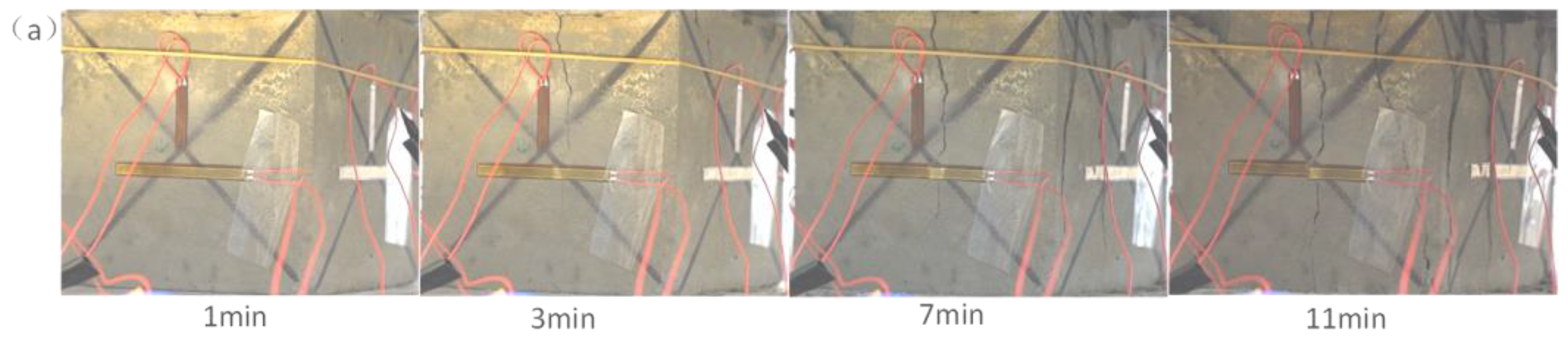
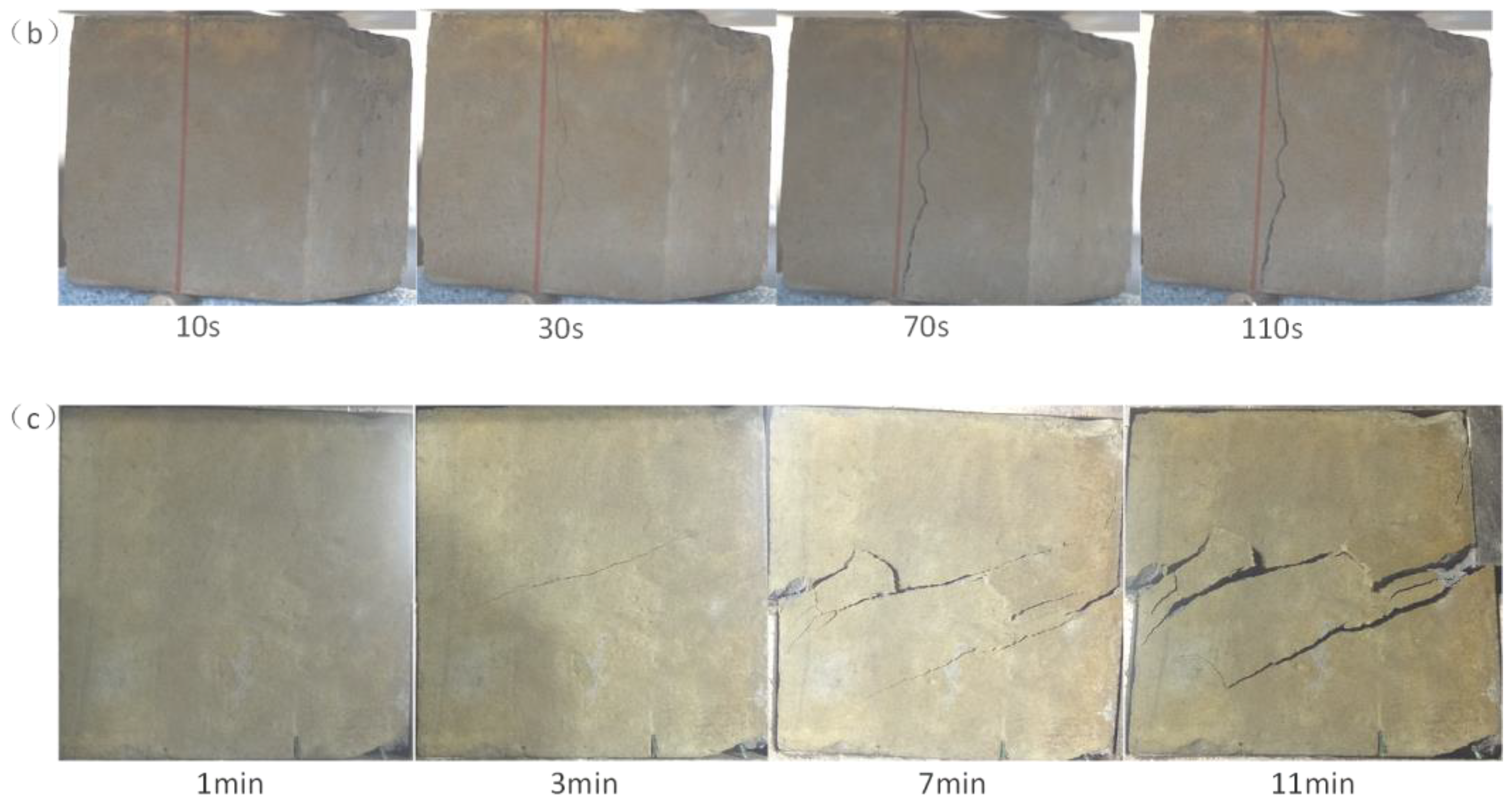
The uniaxial compression test, uniaxial tensile test, and the shear test of the flexible grid filling body were recorded and screenshot, as shown in
Figure 19, and the surface failure characteristics of the flexible grid filling body were analyzed.
As shown in
Figure 19a, there was no crack on the surface of the specimen in the early stage of the uniaxial compressive loading (before 1 min), after which a vertical crack began to appear in the middle of the surface of the specimen, and with continuous loading, the vertical crack gradually expanded and extended to the bottom, developing into a larger crack, accompanied by more vertical parallel cracks until the end of the test. As shown in
Figure 19b, there was no crack on the surface of the specimen in the early stage of the uniaxial tensile loading (before 10 s), after which a small vertical penetrating fracture began to appear in the middle of the specimen surface, and with continuous loading until the end of the test, the penetrating vertical fracture gradually expanded, but no other associated fractures were generated. As shown in
Figure 19c, there were no cracks on the surface of the specimen in the early stage of shear loading (before 1 min), after which an oblique shear crack began to appear in the middle of the specimen surface, developing into a crack, and with continuous loading, the shear crack gradually expanded, and more shear fractures were associated with it until the end of the test.
- (3)
Failure mode of the flexible grid filling body
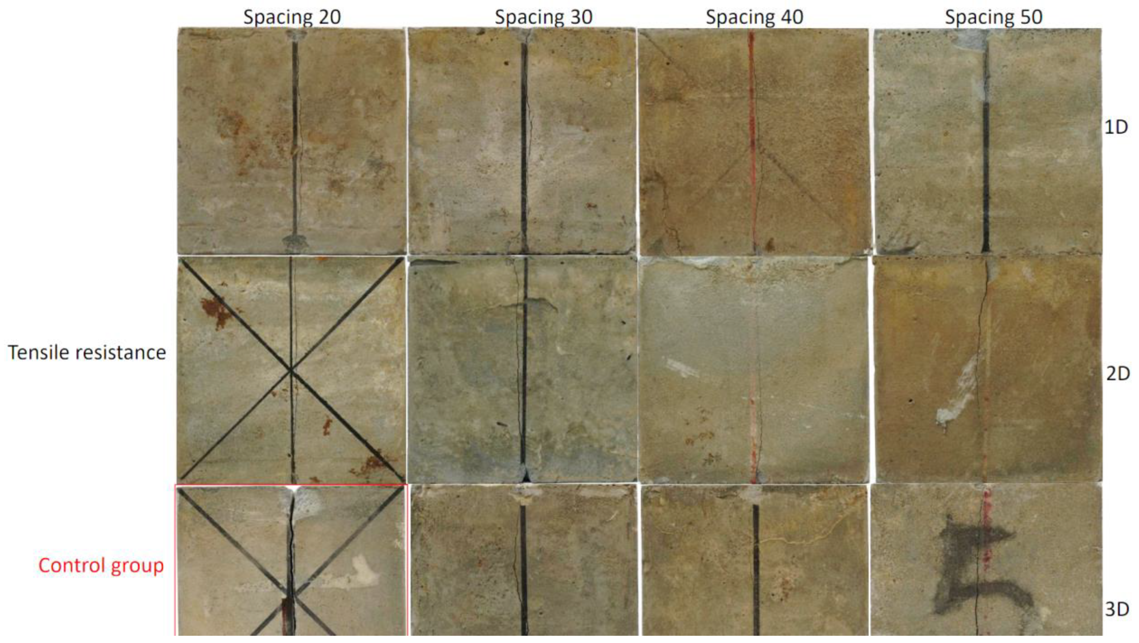
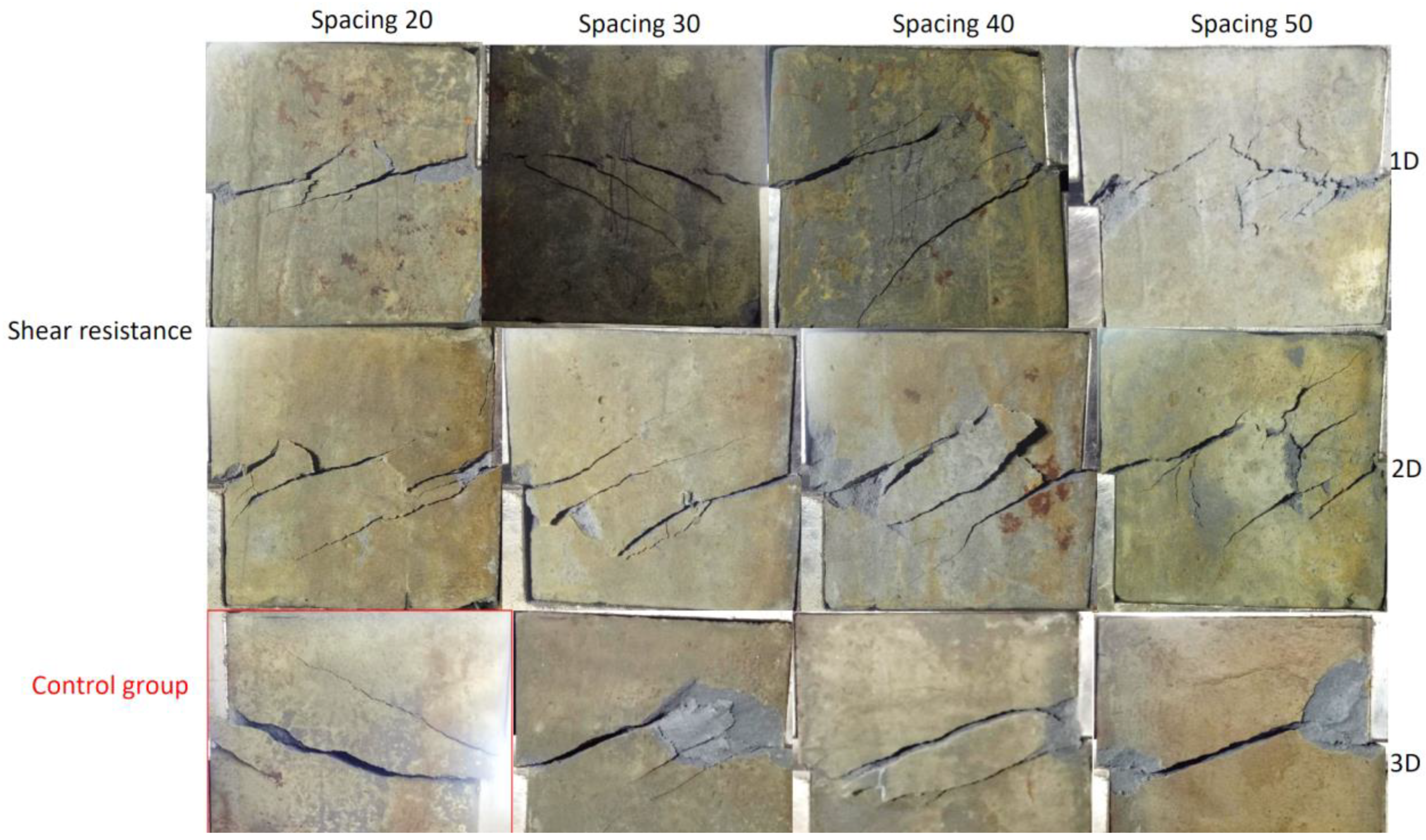
The specimens of the flexible grid filling with different dimensions and spacings were photographed after the uniaxial compression test, uniaxial tensile test, and shear test, as shown in
Figure 20,
Figure 21 and
Figure 22, and their failure mode was analyzed.
It can be seen from
Figure 20 that after the uniaxial compression test of the flexible grid filling body with different dimensions and spacings, the macroscopic failure mode of the specimen was mainly conjugate shear failure, and finally, the “dumbbell shape” of the two ends was large and small.
After the uniaxial tensile test of the specimen with different dimensions and spacings of the flexible grid filling, the macroscopic failure mode of the specimen was tensile failure, as shown in
Figure 21.
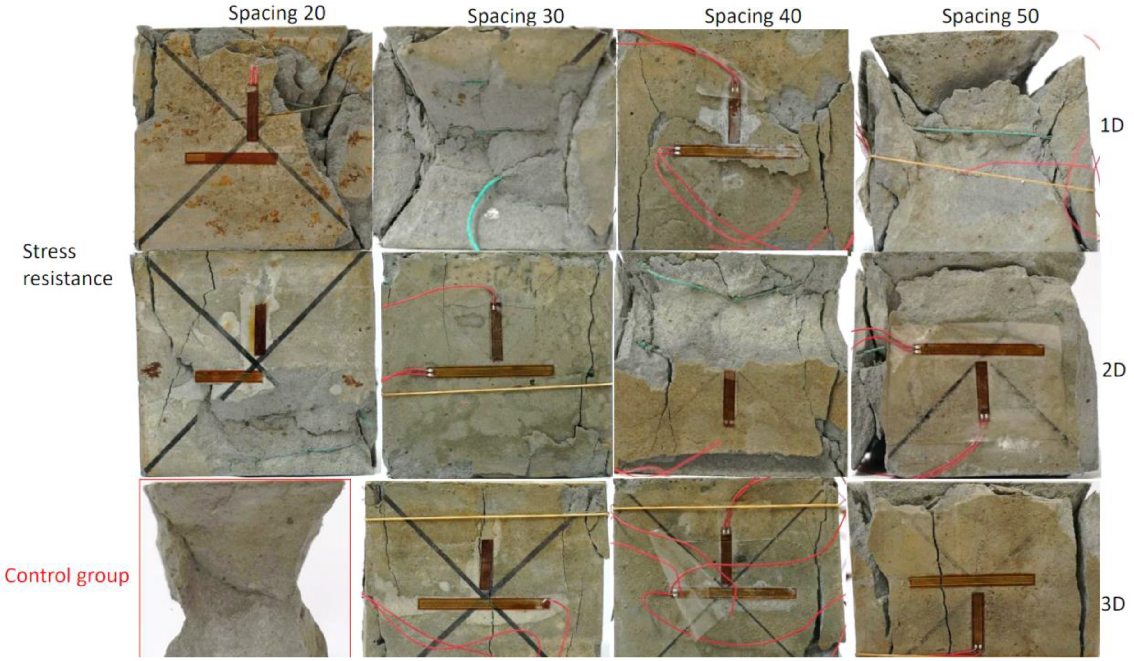
After the shear test of the specimen with different dimensions and spacing, the macroscopic failure mode of the specimen was shear slip failure, as shown in
Figure 22.
Comparing the contours of the flexible grid filling body specimen and the control specimen after destruction, it can be seen that the contour of the flexible grid filling specimen remained relatively intact as a whole, and the fragments generated by the shear damage around the test block after the compression test were relatively uniform; most of them could be attached to the specimen independently, and there was no large peeling phenomenon as with the specimen without the flexible grid filling, as shown in
Figure 20. Similarly, the degree of failure after the tensile and shear tests of the specimen with the flexible grid filling was not as serious as that of the specimen without the flexible grid filling, as shown in
Figure 21 and
Figure 22. This is because the shear strength of the flexible grid rib strip was greater than the shear stress during the shear failure of the filling body, and the shear stress could not cut the flexible grid rib strip to form a large shear surface and cause a large area of shear failure. This phenomenon shows that after the filling body was embedded in the three-dimensional flexible grid, the stress distribution in the filling body specimen was changed, the local concentration of stress in the filling body was reduced, and the bearing strength of the filling body was indirectly improved.
8. Discussion
Using the flexible grid as the reinforcement material, we performed uniaxial compression, tensile, and shear tests of the flexible grid filling body. The following main conclusions were obtained from the experimental results:
The uniaxial compressive strength of the flexible grid filling body gradually increased with the decrease in the grid spacing (the increase in the grid density), but the increase was not large. The uniaxial compressive strength of the flexible grid filling body was independent of the grid dimension, and the uniaxial compressive strength of the grid filling body in the different dimensions (one-dimensional, two-dimensional, and three-dimensional) was basically equal.
The uniaxial tensile strength and shear strength of the flexible grid filling body first increased and then decreased with the decrease in the grid spacing (the increase in the grid density), and there was an optimal grid spacing. The uniaxial tensile strength and shear strength of the flexible grid filling body increased with the increase in the grid dimension; that is, the uniaxial tensile strength and shear strength of the one-dimensional grid < the two-dimensional grid < the three-dimensional grid.
With the uniaxial compression test, the macroscopic failure mode of the specimen was conjugate shear failure, and finally, a “dumbbell shape” with two large ends and a small middle was formed. With the uniaxial tensile test, the macroscopic failure mode of the specimen was tensile failure. With the shear test, the macroscopic failure mode of the specimen was shear slip failure.
From the analysis results, after adding flexible grids in the filling body, the tensile strength, shear strength, elastic modulus, cohesion, and internal friction angle of the filling body were increased to different degrees compared with the ordinary unreinforced filling body. Accordingly, the tensile strength, shear strength, cohesion, internal friction angle strengthening coefficient, and elastic modulus strengthening coefficient of the flexible grid filling body with different dimensions and spacings of the flexible grid fillings were proposed. The results showed that the tensile and shear strengths increased significantly after the addition of the flexible grid in the filling body, whereas the compressive strength increased relatively little.
From the experimental process and the failure of the test block and the coupling effect between the flexible grid and the filling body in the test block, there is a friction passive resistance mechanism between the flexible grid with high tensile strength and the filling body, which makes up for the lack of tensile strength in the ordinary filling body, thereby improving the tensile strength of the flexible grid filling body. The flexible grid filling body is equivalent to improving the cohesion of the filling body without changing the friction angle of the original ordinary filling body, so that the filling body can obtain higher resistance to external loads (compressive strength).
This material can meet the requirements of onsite use, when the compressive, tensile and shear strength of the ordinary filling body cannot meet the requirements of onsite use, such as the need for secondary digging in the filling body, the height of the filling body is too high, etc. One could consider adding a flexible grid to the filling body to meet the needs of use.


 ,
, 


