Article

Recycling Glass and Carbon Fibers for Reusable Components in the Automotive Sector through Additive Manufacturing

1
Department of Chemistry, Materials and Chemical Engineering “Giulio Natta”, Politecnico di Milano, Piazza Leonardo da Vinci 32, 20133 Milan, Italy
2
Design Department, Politecnico di Milano, Via Durando, 20158 Milan, Italy
3
EDAG Engineering GmbH, 36039 Fulda, Germany
*
Author to whom correspondence should be addressed.
Appl. Sci. 2023, 13(10), 5848; https://doi.org/10.3390/app13105848
Submission received: 31 March 2023 / Revised: 1 May 2023 / Accepted: 7 May 2023 / Published: 9 May 2023

Abstract

:
This work explores the use of additive manufacturing (AM) to reprocess recycled glass and carbon fibers in the automotive sector. It aims to foster exploitation of recycled Glass Fiber Reinforced Polymers (rGFRPs) and recycled Carbon Fiber Reinforced Polymers (rCFRPs) through two manufacturing workflows: indirect Fused Filament Fabrication (FFF) and UV-assisted Direct Ink Writing (UV-DIW). An industrial case study on vehicle components has been considered by prototyping one real component. After the tensile tests, some molds were fabricated with a FFF 3D printer for the indirect 3D printing process to cast an epoxy-based thermosetting resin with rGFs and rCFs. The second technology consisted in fabricating the parts by hardening in-situ a photo- and thermal-curable thermosetting acrylic liquid resin with rGFs. These results validate the use of AM and recycled composites for applications in the automotive sector. These approaches may be implemented for customizable components for batches below 100 vehicles as the first step for their exploitation.

1. Introduction

In the next decade, the global composites market is expected to grow steadily, with an annual growth rate of 7.0% [1]. Regulations and legislation are progressively forcing a reduction in the polymer composite landfill, because they are imposing considerable costs for waste disposal landfilling in many countries, thus favoring the investigation of more valuable routes, such as recycling and reuse of End-of-Life (EoL) composites [2,3,4]. Therefore, there is an increasing demand for more application fields for composite materials at their EoL, especially in industrial sectors, such as automotive and transportation, since most research studies on the recycling and remanufacturing of fiber-reinforced polymers are originated in an academic context [5,6]. This need can be fulfilled by developing and combining various strategies and approaches, such as those implemented in the frameworks of circular economy (CE) and cascading [7] and of Design for Sustainability [8], which have certainly fostered some examples of green design and eco-design principles. Moreover, the effectiveness of all these strategies for more sustainable development should be assessed quantitatively by using circularity metrics [9], which should monitor and minimize the environmental impact induced by circular and sustainable policies [10].
To promote sustainable and environmentally-friendly development, manufacturing industries also need to improve product design and production processes [11], and this can be achieved by shifting to additive manufacturing (AM) technologies, which are able to support a more sustainable production than conventional manufacturing methods due to several AM sustainability advantages [12,13,14]. In the light of these benefits, AM technologies can also encourage the use of recycled glass fibers (rGFs) and carbon fibers (rCFs) without worsening performance when compared to virgin fibers [15,16]. AM is already exploited in the automotive sector to produce spare parts, for which carbon fiber-filled thermoplastic composites were 3D printed to produce some components of out-of-production cars [17,18]. However, there is a lack of AM adoption to produce real automotive components, especially exploiting rGFs and rCFs, as well as cross-linkable polymer matrices.
This work explores the use of AM technologies to reprocess rGFs and rCFs for new applications in the automotive sector, aiming to foster real exploitations of rGFRPs and rCFRPs through 3D printing. In detail, it shows two possible workflows, indirect FFF 3D printing and UV-DIW. The experimentation comes from an industrial case study on reusable vehicle components and uses one part of a new concept of car structure as a benchmark. The two paths for the fabrication of the pieces are explained and discussed after describing the two process workflows and the industrial case study, supported by tensile tests. The preliminary results of this work validate the use of rGFRPs, rCFRPs and AM technologies for real applications in the automotive sector. As a result, the two approaches may be implemented in industrial contexts for small batches of customizable components and prototypes, paving the way for the practical implementation of these new recycled composite materials and AM technologies.

2. Materials and Methods

2.1. Materials

Recycled glass fibers derive from shredded GFRPs from wind turbine blades after their dismantling (Siemens Gamesa Renewable Energy S.A., Zamudio, Spain, and Consiglio Nazionale di Ricerca—Sistemi e Tecnologie Industriali Intelligenti per il Manifatturiero Avanzato—Stiima CNR, Milano, Italy). The rGFRP powders contain 70% wt. of GF and have a nominal granulometry < 80 μm, 200 μm and 1 mm [19,20,21]. Recycled carbon fibers come from expired pre-impregnated CFs (prepreg), which underwent pyrolysis, sizing, and shredding processes (Aernnova Aerospace S.A., Minano Mayor, Spain—Tecnalia Research & Innovation Center, San Sebastiano, Spain—Stiima CNR). The rCF powders have a nominal granulometry of 63 μm and 200 μm [21,22]. The different recycled fibers are visible in Figure 1.
An ethoxylate bisphenol A diacrylate resin (SR349) was used as a matrix in the ink formulations for the UV-DIW process (Arkema, Colombes, France) together with ethyl phenyl (2,4,6-trimethyl benzoyl) phosphonate (TPO-L) as photo-initiator (Lambson Limited, Wetherby, UK), and dicumyl peroxide as a thermal initiator (Sigma-Aldrich Corporation, St. Louis, MO, USA). In addition, 3% wt. of TPO-L and 0.3% wt. of dicumyl peroxide were added to SR349 to initiate photo-polymerization and increase crosslinking during thermal post-curing. An epoxy-based thermosetting resin made of bisphenol-A-based oligomer and 1,4-butanediol di-glycidyl ether (Araldite BY158) was used as a matrix, in order to pour for indirect FFF 3D printing (Huntsman Corporation, The Woodlands, TX, USA), together with a curing agent (Aradur 21) in the weight ratio of 100/28 (Huntsman Corporation).
Polyethylene terephthalate glycol (PETG) and polylactic acid (PLA) filaments were used to fabricate the rigid molds and silicone counter molds of the indirect FFF 3D printing workflow (Prusa Research, Prague, Czech Republic). A poly-addition casting silicone rubber with a hardness of 30 ShoreA (Gls-PRO 30) was poured into the rigid molds and silicone counter molds to obtain the molds for the final parts (Prochima Srl, Colli al Metauro, Italy). This silicone is made of two reagents, to be mixed at a volume ratio of 1:1.

2.2. Indirect FFF 3D Printing

The term Indirect 3D printing refers to the use of 3D printing processes to manufacture the tooling used in conventional manufacturing to obtain a component or a part, i.e., molds, inserts and utensils [23]. This workflow comes from the Rapid Tooling techniques and may help in fostering quick, customizable, and less expensive manufacturing of tools for prototypes, pre-series, or small batches of production, ranging from small- to large-scale products [24,25]. In this work, customizable mold silicone cavities were designed and manufactured to produce the parts from the automotive case study. The molds were designed using the CAD software Fusion 360 (Autodesk, San Rafael, CA, USA), and the slicing software PrusaSlicer was used to create the gcode files to be printed (Prusa Research, Prague, Czech Republic). The same CAD software was also used to modify the STEP files of the component used for the experimentation, better described in Results and Discussion. The rigid parts of the counter mold silicone were printed with the low-cost desktop-size FFF 3D printer Prusa i3 MK3S equipped with a 0.6 mm diameter nozzle (Prusa Research, Prague, Czech Republic). The 3D printing parameters of the molds and counter molds are summarized in Table 1. In detail, the parameters of the molds, in particular infill, were chosen to create mechanical interlockings for the silicone cavities to be poured, as better explained in the next section [26]. The parameters of the counter molds were selected to reduce the possibility of leakages during the curing phase of the silicone. The silicone cavities were manufactured by pouring the Gls-PRO 30 silicone into the assembled molds and counter molds, which were removed after 24 h of curing at room temperature.
The molds were then used to fabricate the component parts with the epoxy-based thermosetting resin filled with shredded rGFRPs or rCFs. First, Araldite BY158 and Aradur 21 in the weight ratio of 100/28 were mixed to obtain the epoxy-resin based matrix with a gel time of 80 min, corresponding to the maximum processing time of the material formulations before starting to harden. The shredded rGFRPs or rCFs were then added to the matrix and mixed for 15 min with a mechanical stirrer at 50 rpm. In detail, 30% wt. of rGFRPs (200 μm or 1 mm) and 20 or 30% wt. of rCFs (63 μm or 200 μm) were added to the epoxy-based system, obtaining four different formulations to test: 30% wt. rGFRPs (200 μm), 30% wt. rGFRPs (1 mm), 20% wt. rCFs (63 μm), and 30% wt. rCFs (200 μm). After mixing, these mixtures underwent a low vacuum level for 15 min to reduce the presence of air bubbles. After processing, the molds were kept for 24 h at room temperature. Parts were then removed from the mold and underwent a post-curing of 1 h at 100 °C to complete crosslinking of the thermal-curable epoxy-based matrix. Post-processing was then performed to remove the extra material corresponding to the pouring channels. At least two prototypes of the cut-off and final part were fabricated for each set of parameters and material formulation.

2.3. UV-Assisted Direct Ink Writing (UV-DIW)

UV-assisted DIW consists of the 3D printing of a photo-curable viscous material, or 3D printable ink, that starts to harden after the extrusion by means of a UV source, i.e., UV LEDs. This process allows processing of new kinds of materials at room temperature, i.e., thermosetting composites, starting from a photo- and thermally-curable 3D printable ink. In this work, SR349 was mixed with 3% wt. of TPO-L and 0.3% wt. of dicumyl peroxide for 2 h at room temperature with a magnetic stirrer, then 55% wt. of shredded rGFRPs (<80 μm) were added to the acrylic-based system by means of a double arm kneader Brabender mixer equipped with a rollerblade (Brabender Instruments Inc., South Hackensack, NJ, USA) for 45 min at 40 rpm. The glass fiber content of the ink formulation corresponds to 38.5% wt. [20,21].
A commercial low-cost desktop-size FFF 3D printer (Futura Group S.r.l., Gallarate, Italy) was modified to create a UV-DIW apparatus. A new syringe-based extruder equipped with three dimmable 3W UV LEDs (395 nm) on the extrusion head was developed and mounted on the 3D printer frame [20,21]. The custom system was equipped with a 60 mL syringe for the ink formulation and a stainless-steel UV-shielded conic nozzle with a diameter of 1.04 mm (Techcon Systems Inc, Cypress, CA, USA). The STEP files of the components were modified with Fusion 360, and the gcodes were created with PrusaSlicer. The 3D printer was controlled through the 3D printing host Repetier-Host (Hot-World GmbH & Co. KG, Willich, Germany). UV LEDs were switched on for the whole duration of the 3D printing process. The main parameters are summarized in Table 2. More details about the process and the conditions used can be found in a previous study focusing on the printability of this formulation [20].
After the 3D printing process, an additional post-curing cycle was required to complete the crosslinking conversion of the resin. The parts underwent a UV post-curing step for 30 min in a UV chamber Polymer 500 W equipped with a UVA emittance mercury vapor lamp Zs of 950 W/m2 (Helios Italquartz S.r.l., Cambiago, Italy). After this step, an additional thermal post-curing was performed in an oven for 2 h at 140 °C. At least two prototypes of the selected part were fabricated for each set of parameters and material formulation.

2.4. Tensile Tests

Tensile tests were performed with a Zwick Roell Z010 (ZwickRoell GmbH & Co, KG, Ulm, Germany), with a 10 kN cell load and a speed of 1 mm/min, following the ASTM standard D3039/D3039M-17 [27]. Four batches of specimens were tested: (i) 30% wt. rGFRPs (200 μm)—indirect FFF, (ii) 30% wt. rGFRPs (1 mm)—indirect FFF, (iii) 20% wt. rCFs (63 μm)—indirect FFF, (iv) 30% wt. rCFs (200 μm)—indirect FFF, compared with (v) 55% wt. rGFRPs (<80 μm)—UV-DIW from previous work [20]. The specimens had a nominal width of 10 mm, length of 40 mm, and thickness of 2 mm (gauge length of 40 mm). They were manually polished to remove the main asperities from the epoxy resin pouring, ensuring a constant cross-section area. The actual dimension was then measured with a caliper. After the tests, the mean values and standard errors of tensile strength, elongation at break, and elastic modulus were calculated using the stress–strain curves from the tests.

3. Results and Discussion

3.1. Case Study from the Automotive Sector

The selected case study was part of the Horizon 2020 European project FiberEUse, focused on the recycling and reusing of glass and carbon fiber composites from products at their End-of-Life. This project aimed to develop new solutions integrated into real contexts through practical case studies in collaboration with industrial partners. Among these, the automotive sector was selected to demonstrate the feasibility of using CFRPs for reusable structures and components in a vehicle frame [28,29]. As a matter of fact, technical lightweight and high-performance application fields such as the automotive sector may significantly take advantage of the reuse and recycling of GFs and CFs [30,31], i.e., reducing the manufacturing costs and decreasing the environmental impact during the production and use of components [6,32].
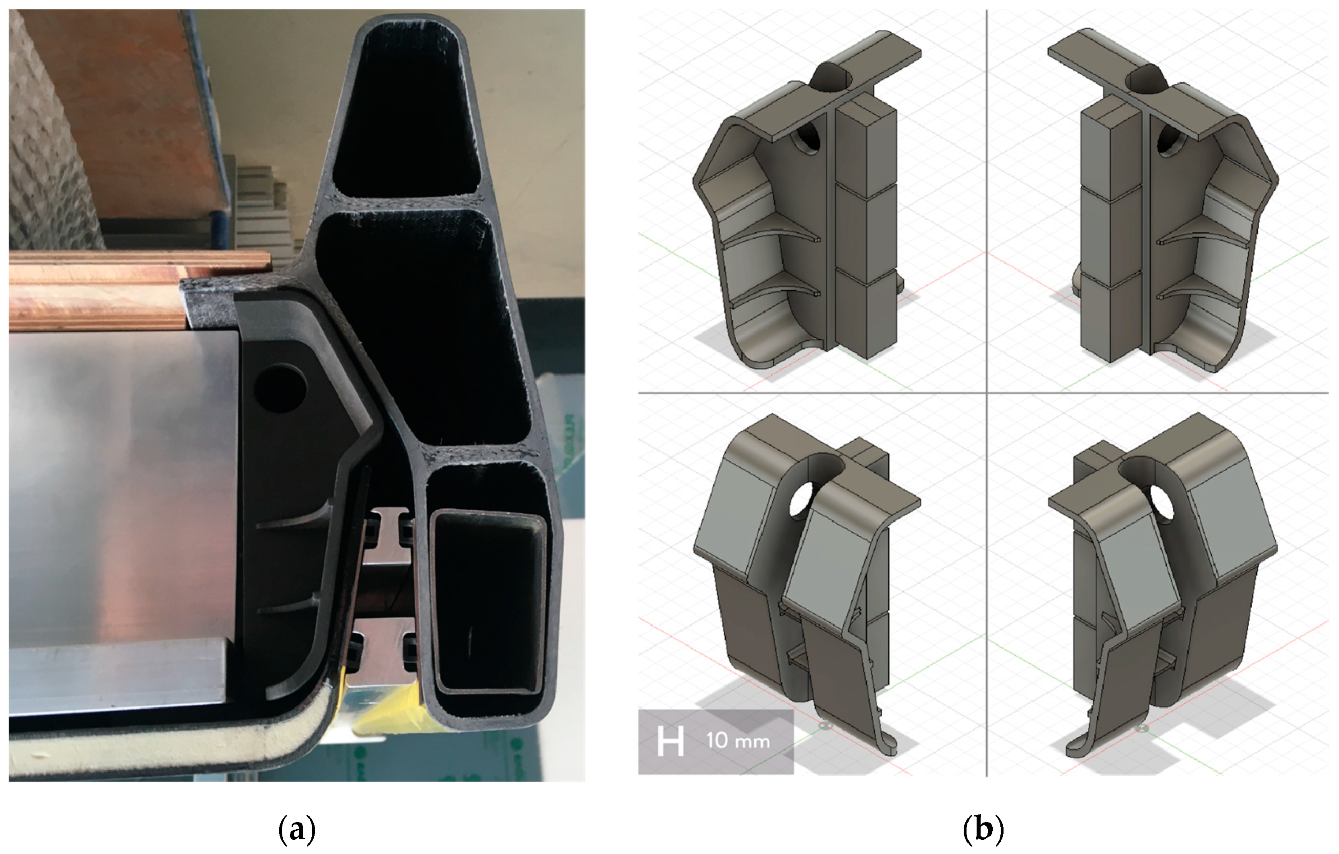
Focusing on recycling, the automotive sector offers a wide range of possible areas for using recycled fibers, both rGFs and rCFs [6,33]. A case study of a structural part in the battery housing was selected because this part of the car structure is seen as critical in crash incidents, representing an interesting use case for new composite polymers reinforced with rGFs or rCFs. The structural part under examination, visible in Figure 2a, is a connecting element between the rocker panel and a reinforcing aluminum rib inside the battery housing. The main load case of the part is the provision of stiffness, defining it as a structural part of this sub-assembly. In battery housing, six of these elements are needed. In a crash incident, in particular a side pole crash, it takes up the loads from the deformation of the rocker panel and supports it by leading the loads into the reinforcing profiles. This fact leads to a safe battery compartment that is not prone to intrusions leading to damage to the batteries.
The selected part, as visible in Figure 2b, consists of a wide connection area that fits closely to the sill and absorbs the forces, as well as to the so-called battery floor pan. Ribs are used to collect these forces and lead them into the aluminum profile. For that purpose, the shape of the profile, including the webs, is mapped, creating a connection by form. The part is then fixed by an epoxy adhesive to the aluminum profile and the battery floor pan. A material bonding to the sill is not applicable since the battery compartment must stay detachable for repair and remanufacturing. A feature of the part is a central guidance hole for a cable. The part is designed in a moldable shape because, considering the batches of mass production, it is expected to achieve higher production rates of about 10,000 pcs./year.
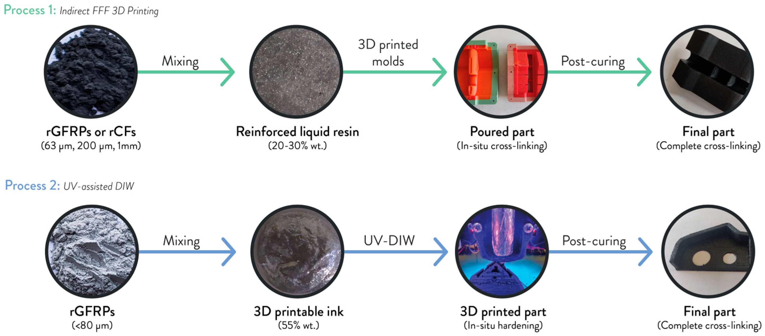
Focusing on AM processes, this case study, as well as the part, was chosen to demonstrate the possible use of 3D printing processes in the automotive sector for reprocessing rGFs and rCFs. Despite its quite recent adoption in this sector, AM processes have already been demonstrated to positively affect the supply chain performances of automotive industries, as well as fostering customization and complex freeform structures in medium and small production batches [34,35,36]. Furthermore, AM has already been exploited for manufacturing fiber-reinforced polymer materials, including recycled rGFs and rCFs [37,38]. As visible in Figure 3, two different workflows were followed to exploit different advantages of AM technologies, especially focusing on Material Extrusion processes [39]. The first deals with Rapid Tooling and uses FFF to manufacture 3D-printed molds to cast rGFRPs or rCFRPs (indirect FFF 3D printing), whereas the second directly reprocesses rGFRPs by means of UV-DIW (Figure 3). The main phases of the two processes are summarized in Figure 4.

3.2. Tensile Tests

Five batches of specimens were tested to study the main tensile properties of the formulations used in this work. Four of them are linked to Indirect FFF 3D printing, whereas the last one corresponds to the UV-DIW formulation used for the automotive application and previously tested [20]. The values from the tensile tests are summarized in Table 3.
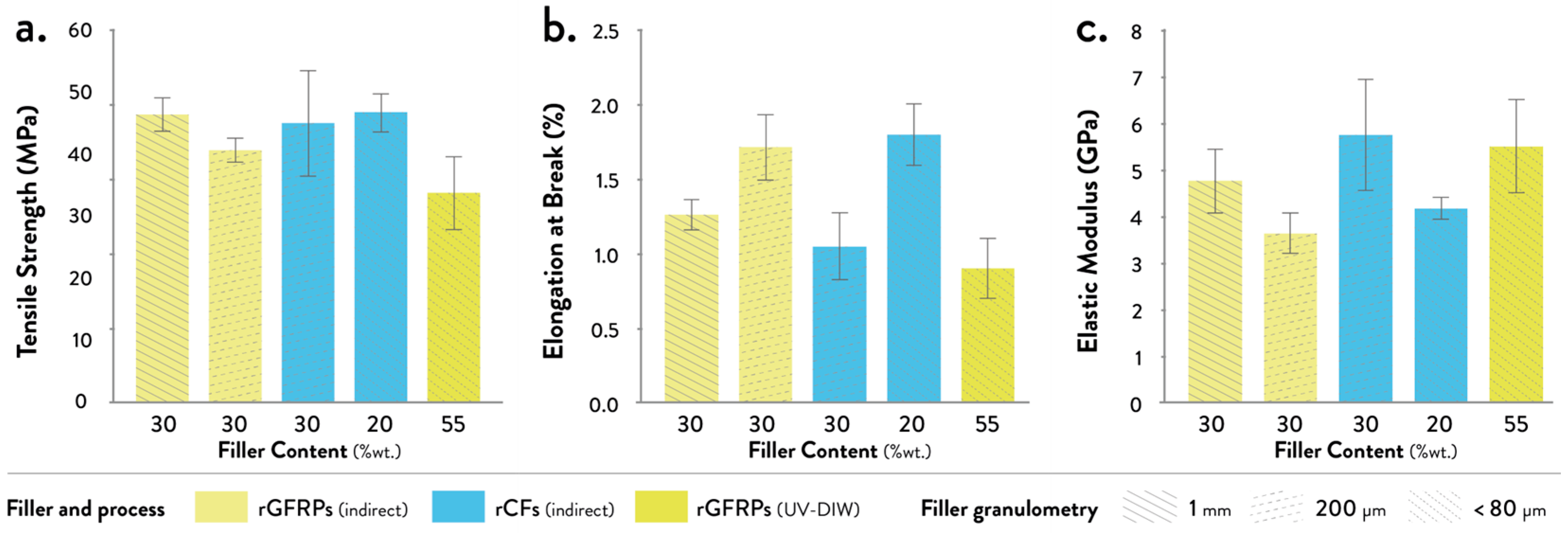
In general, a brittle failure of the samples was observed for each batch. According to Table 3 and Figure 5, higher values of tensile strength and elongation at break were obtained by testing the samples from indirect FFF 3D printing.
Despite the higher filler content of the UV-DIW formulation, i.e., 55% wt., the tensile strength of specimens from indirect FFF shows higher values when considering the same kind of recycled fibers, which means rGFRPs (Figure 5a). As a matter of fact, the first (30% wt. rGFRPs 1 mm) and second batches (30% wt. rGFRPs 200 μm) reached values between ~40 and ~46 MPa, whereas the tensile strength of UV-DIW batch is ~33 Mpa. This difference can be linked to the higher void content from the increased weight percentage of fibers, especially with higher granulometries [40,41]. Furthermore, additional voids may be added from the UV-DIW process itself, i.e., air bubbles in the 3D printable ink during the in-situ photo-polymerization [20,21]. Similar values were obtained by comparing rGFRPs and rCFs from indirect FFF, with higher accuracy of results by decreasing the particle size of the filler. This fact may be due to the high variability of the granulometry, which also derives from mechanically recycled fiber-reinforced polymers [20,21,22].
Almost a two-fold increase in the elongation at break values was reached with rGFRPs processed by indirect FFF compared to the UV-DIW process, reaching ~1.7% with the second batch of samples (Figure 5b). A similar value was also obtained from the batch of samples made with 20% wt. of rCFs (63 μm). Increasing the filler weight percentage and particle size, the value significantly decreased for both rGFRPs and rCFs batches.
The batches made with rGFRPs using Indirect FFF show an increase in the elastic modulus with higher particle sizes (Figure 5c). Similarly, the stiffness of rCFs batches increased by increasing the particle size and filler weight percentage, reaching ~5.8 GPa. A similar value was also obtained by using rGFRPs and UV-DIW, thanks to a higher content of filler and the preferential alignment during extrusion [42,43,44].
To sum up, the materials tested in this work seem to be suitable for the selected application in the automotive sector, especially considering their stiffness, both for direct and indirect AM processes [18].

3.3. Indirect FFF 3D Printing

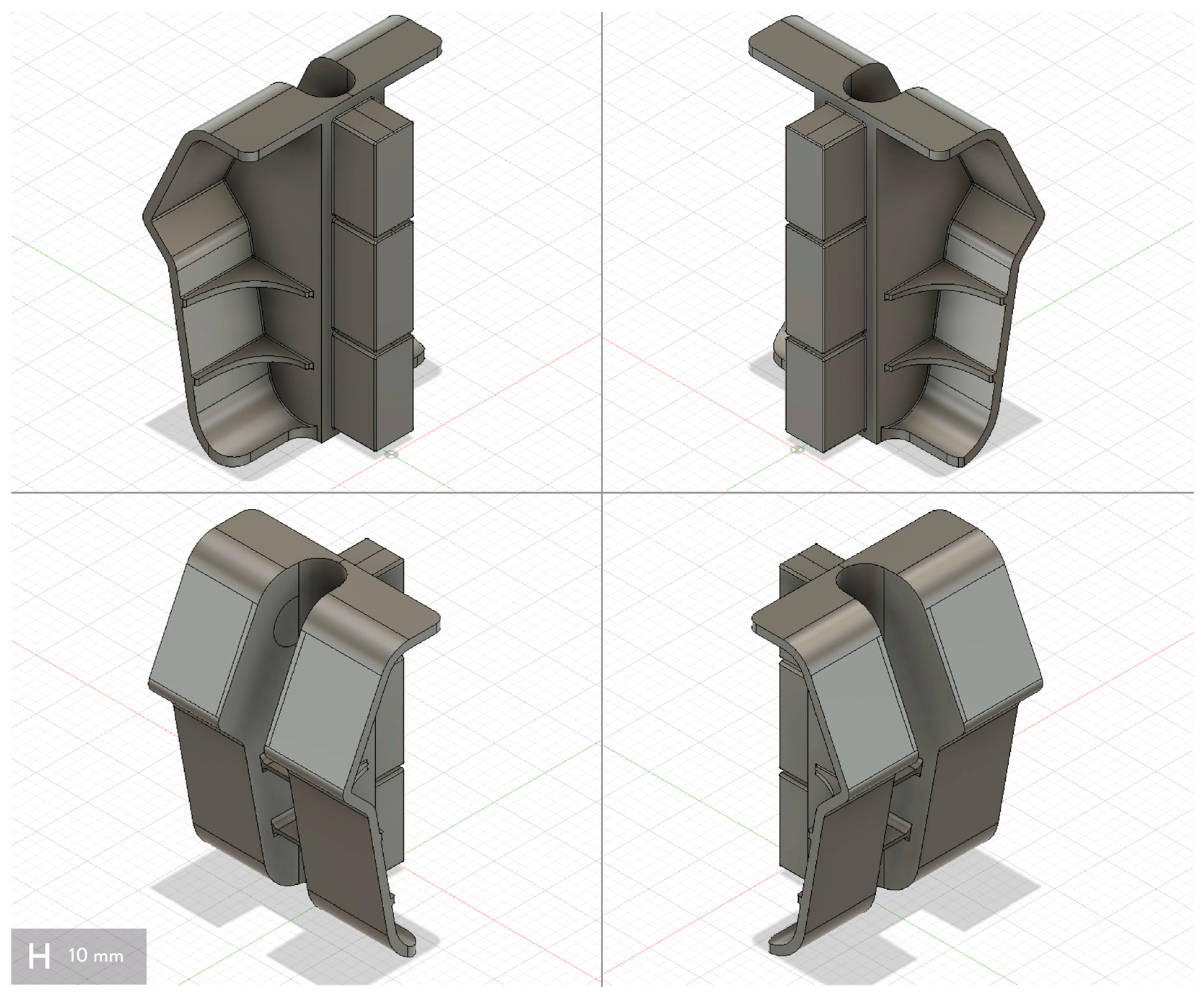
This experimentation validated the first workflow shown in Figure 3 and Figure 4. In detail, indirect FFF 3D printing was selected to manufacture the component in Figure 2b, avoiding sub-assemblies or cut-offs and reprocessing a wider range of recycled fiber-reinforced composites as new reinforcements for epoxy-based resins, in this case both rGFRPs and rCFs. As shown in Figure 6, only a few modifications were made to the original version of the 3D model. First, some features, such as the central guidance hole, were removed to eliminate possible overhangs and undercuts during the extraction of the component from the hypothetical mold. In this case, a drilling process would be performed after removing the part from the mold. Moreover, some radii were added to the main sharp angles to facilitate the distribution of the material into the mold cavity, as well as a possible source of cracks and failures in the final part. Finally, the thicknesses of the whole model were checked to avoid thin cross-sections and ensure quite uniform measures, ranging between 2 and 4 mm, hence facilitating the curing process.
Considering the geometry and the selected thermoset composite materials, flexible cavities were included in the design of the mold to facilitate the extraction of the parts, as well as the complete hardening of the epoxy resin after its pouring. Furthermore, choosing silicone for manufacturing the cavities avoided their deformation during the hardening reaction of Araldite BY158, which generates exothermic heat.
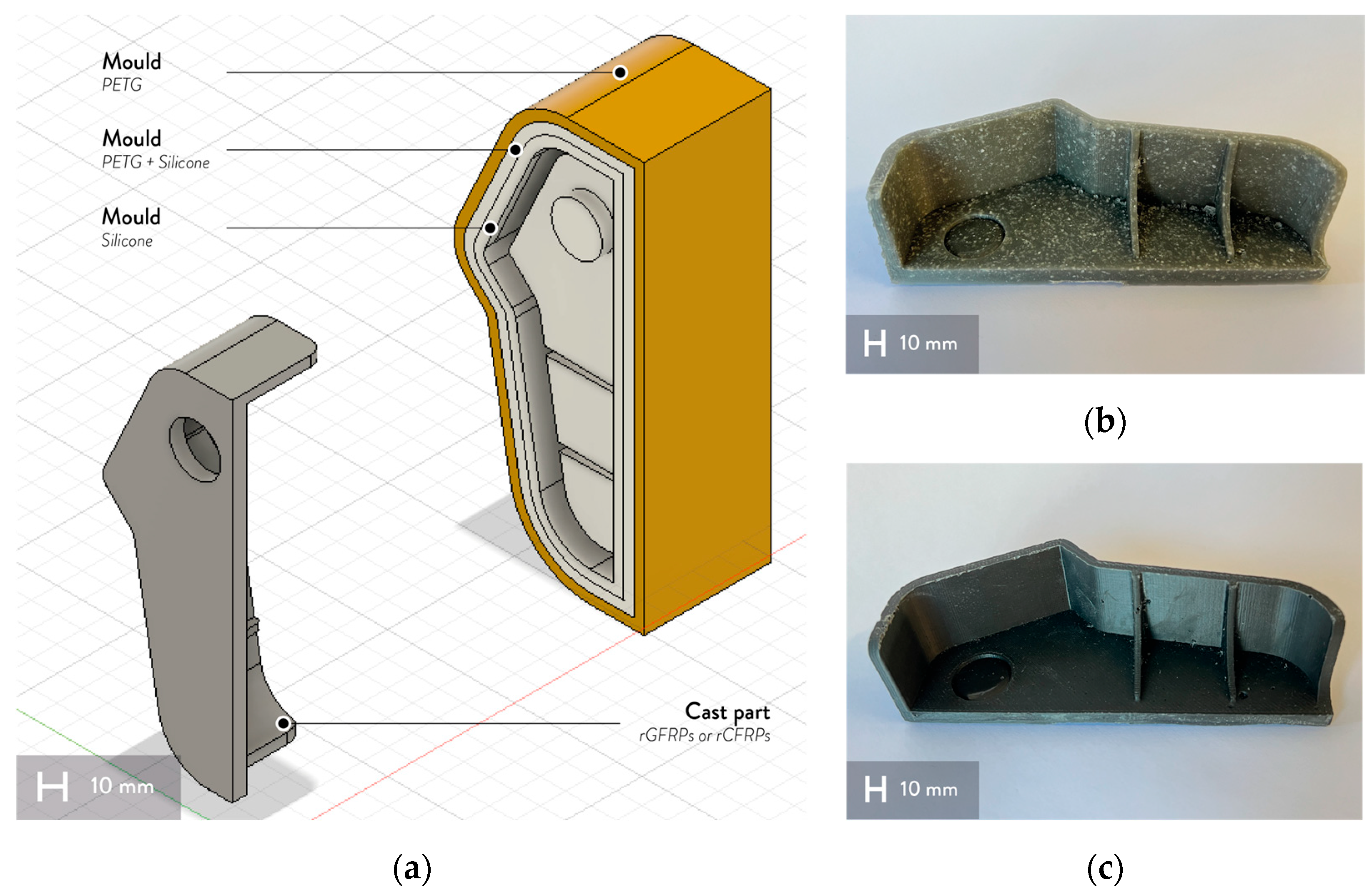
To validate the use of silicone in the final design, some trials with a cut-off of the part were done by designing and manufacturing a 3D-printed open mold with a silicone cavity. As from Figure 7a, the mold consisted of an external rigid part in PETG fabricated through FFF 3D printing and a flexible part obtained by pouring the Gls-PRO 30 silicone into the rigid mold. The shape of the cavity was given through a 3D-printed counter mold made of PLA, which was removed after silicone curing. The bonding between silicone and PETG was obtained by designing and fabricating mechanical interlocking areas inspired by the work of Rossing et al. [26]. The “modifier” feature of PrusaSlicer was used to change the slicing parameters of a specific section of the model to be 3D printed [45], which means the rigid part of the mold. In this case, the interfacial area was fabricated by changing the type and percentage of infill, i.e., 40% gyroid, and removing top layers, creating a controlled porosity in the mold. In this way, liquid silicone can pass through the infill part and fill the empty spaces, ensuring mechanical interlocking after its complete curing. The gyroid infill was selected to increase the volume of the rigid interlocking structure, whereas the whole structure was designed entirely in PrusaSlicer to simplify its development and manufacturing by avoiding using parametric design tools.
Figure 7b,c show the parts obtained by pouring the epoxy-based thermosetting resin filled with rGFRPs and rCFs. In detail, the first epoxy-resin based formulation (Figure 6b) contains 30% wt. of shredded rGFRPs with a mean granulometry of 1 mm, whereas the second one (Figure 6c) has 20% wt. of shredded rCFs with a mean granulometry of 63 μm, which were also selected according to the previous tensile tests. Even if both part batches were successfully fabricated with the same open mold, more deformations are visible in the part made of rGFRPs, which also shows a higher presence of air bubbles, especially close to the radii and the ribs. This issue may be linked to the higher thermal conductivity of CFs, which helps in dissipating the heat from the exothermic reaction from the crosslinking of the epoxy-based resin [46,47].
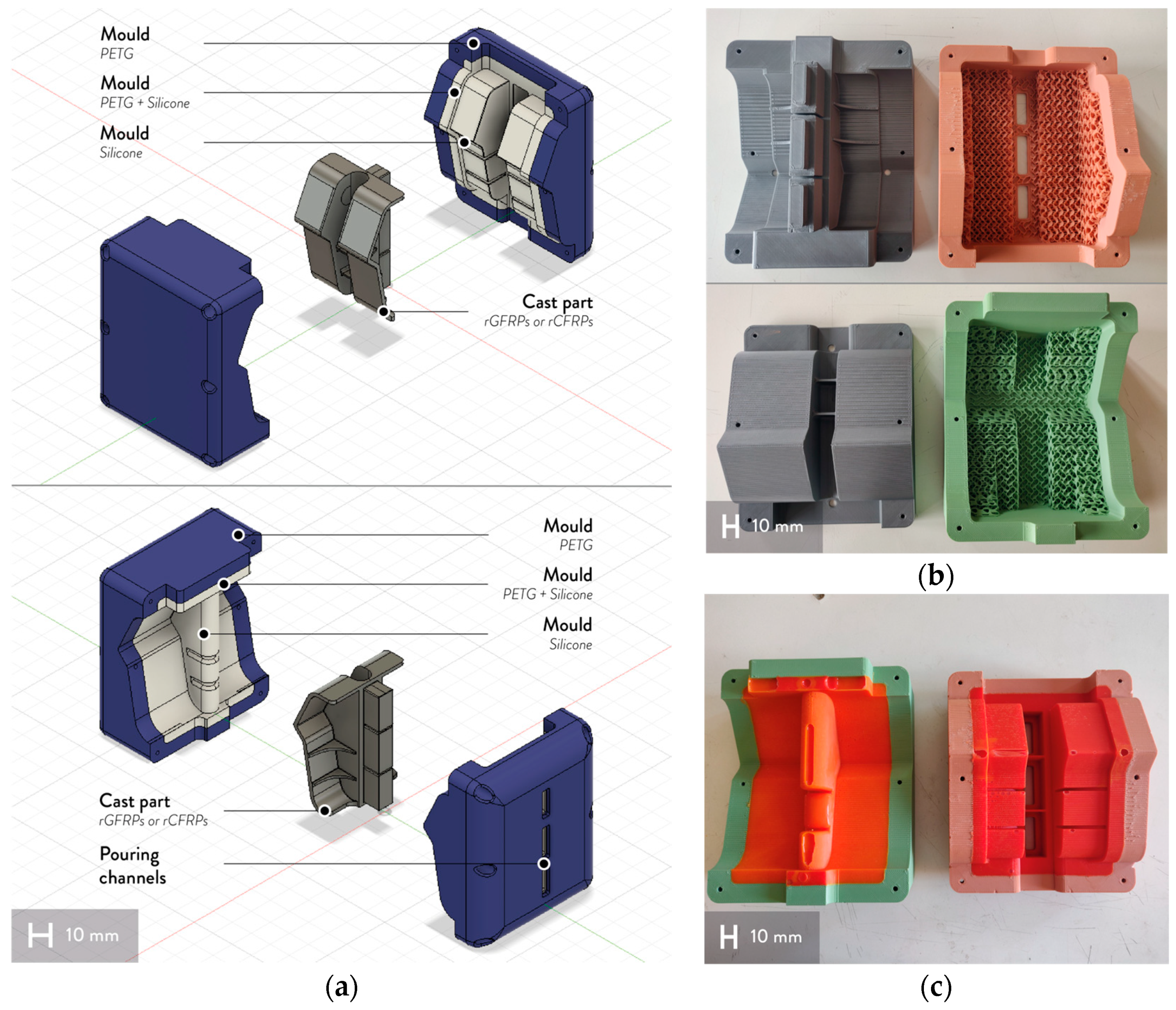
After this first trial using an indirect FFF 3D printing approach, the mold of the part was designed and manufactured to produce it as a single component. As shown in Figure 7a, this mold comprises two halves, which were manufactured by following a similar approach used to fabricate the cut-off part described before. The mechanical interlocking between the rigid mold and the flexible cavity was developed by designing the specific shape of the modifier features in the CAD software, which was then imported into Prusaslicer. Furthermore, the final design of the rigid parts was obtained by avoiding the use of any support material, trying to reduce the material waste, and the 3D printing timings for the production according to the principles of Design for Additive Manufacturing (DfAM) [48]. The counter molds were fixed on the rigid molds through six metric M5 screws by using the same design for the assembly of the final mold. The pouring channels were designed in the upper half of the mold by linking them to the flat surfaces on the back part of the component (Figure 8a). The counter molds and rigid molds are visible in Figure 8b, whereas Figure 8c shows the final molds with the flexible cavities after silicone curing. Although the silicone successfully reproduced the shape of the counter molds, some defects were generated by the presence of air bubbles in the mixture, (Figure 8c).
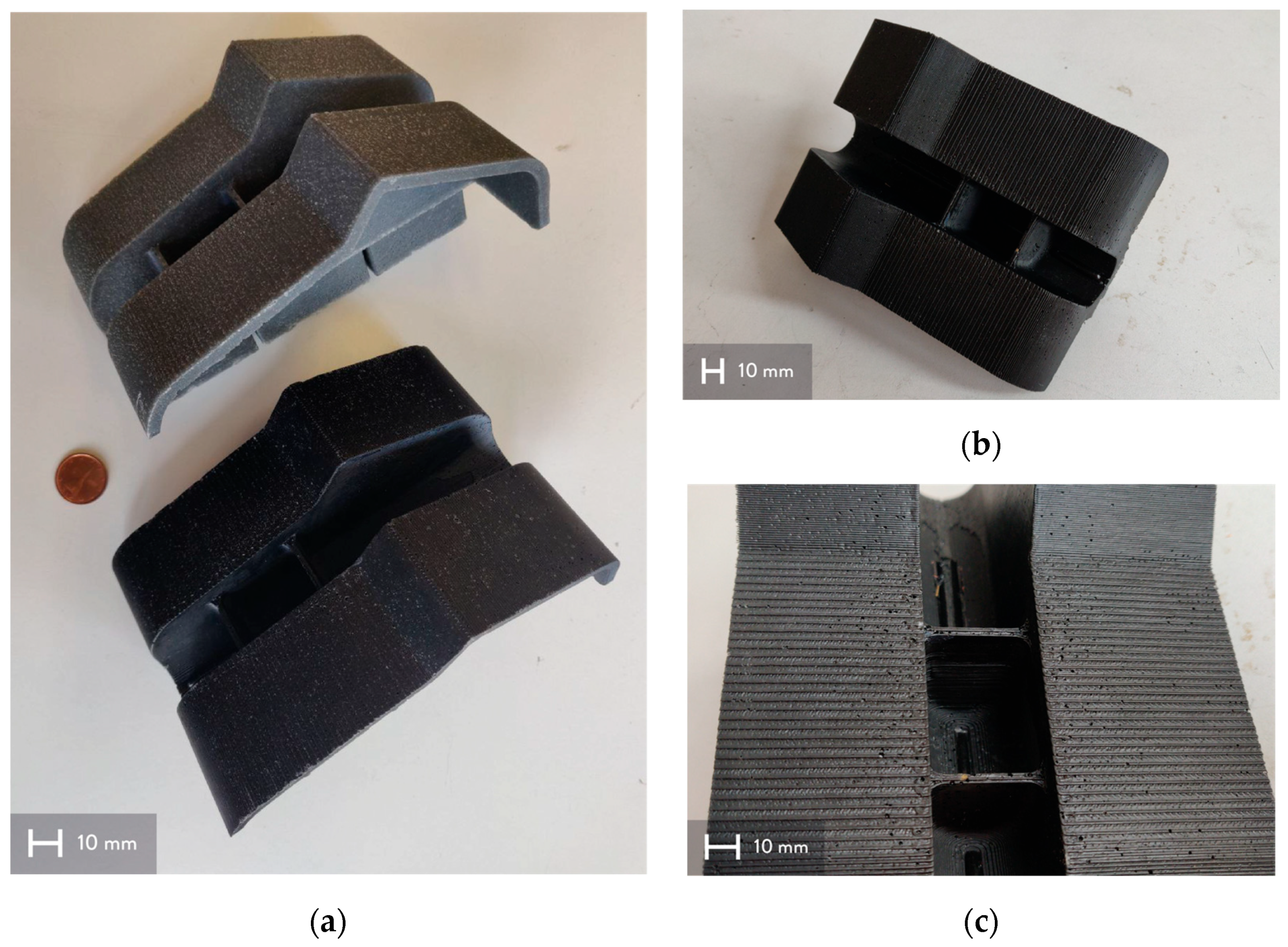
The final parts from the mold are visible in Figure 9a. The part at the top has 30% wt. of shredder rGFRPs with a mean granulometry of 200 μm, whereas the bottom one contains 30% wt. of shredded rCFs with the same mean granulometry. These two formulations were selected according to the previous tests, choosing the same percentage and particle size in both formulations. Especially in the rCFs batch (Figure 9b), no visible deformations were seen in both batches, as well as fewer air bubbles in the final parts, reducing the possible points of cracks in the event of an accident. Some post-processing is still required to remove the three pouring channels attached to the back part, and some defects of the silicone casting can be seen on the front part (Figure 9c). However, these results validate the use of this workflow linked to indirect FFF 3D printing to prototype and produce small batches of customized components for technical sectors made of recycled GF or CF composites, i.e., automotive. The functional aim of the part, i.e., absorbing the forces from the battery floor pan of the car structure, can be achieved by this component manufactured with indirect FFF 3D printing, also considering the properties of similar rGFRPs [19] and the use of GFs and CFs for similar purposes in the automotive sector [28,29].

3.4. UV-Assisted Direct Ink Writing (UV-DIW)

UV-Assisted DIW was selected as a manufacturing process to use in the second workflow from Figure 2. In this case, the selection was made to avoid the use of molds or tools, trying to reduce the costs and timings related to their manufacturing. First trials were performed by using both rGFRPs and rCFs as reinforcements for photo- and thermally-curable acrylic resins. However, the final parts were fabricated only with rGFRPs. As a matter of fact, the presence of rCFs in the 3D printable ink interferes with the absorption of the UV radiation for the activation of the photo-initiator in the acrylic-based matrix system [21,22]. Hence, only a few layers were successfully completed without collapsing during the first 3D printing tests with rCF-based inks.
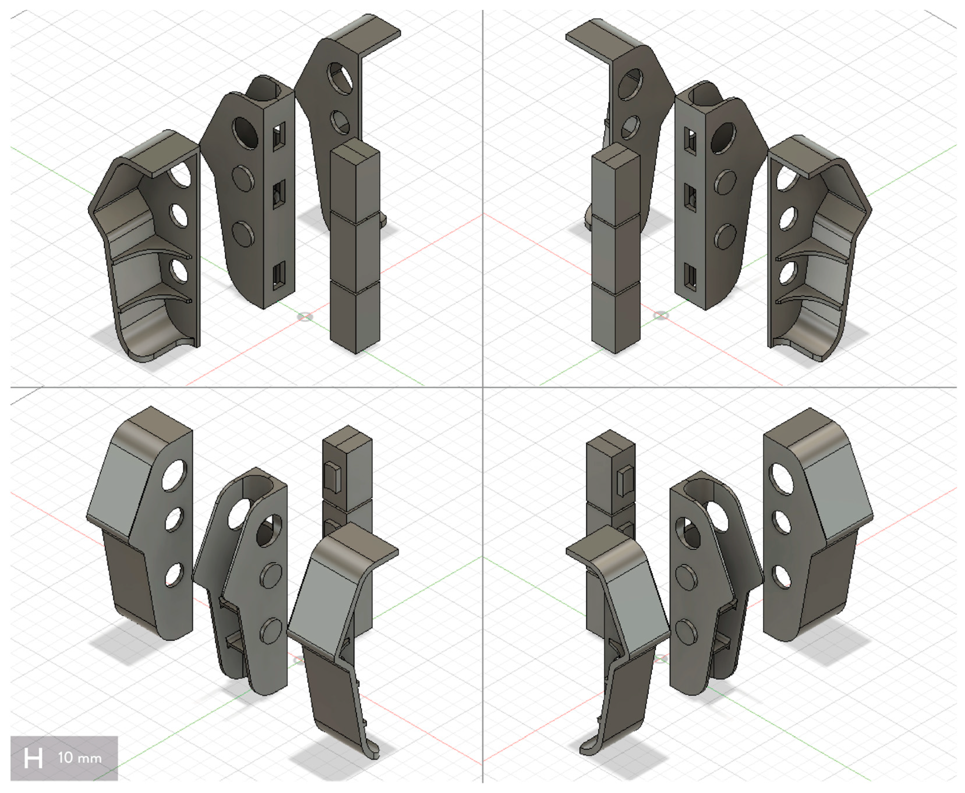
As visible from Figure 10, the original model was strongly modified to match the manufacturing constraints of UV-DIW. First, the use of supports should be avoided, since they may be difficult to remove from the final shape, requiring more post-processing steps. Furthermore, the volumes and dimensions of the parts should be optimized to avoid long printing times, i.e., >8–10 h, obtaining functional parts for technical applications [16]. In UV-DIW, the printing speed is affected by the UV conversion and the cross-section geometries, resulting in higher times and slower speeds when the UV-irradiation time should be increased to completely crosslink the ink [21]. As a result, the original model was cut into six different parts, avoiding overhangs and tilted surfaces to be 3D printed. This modification helped in optimizing the printing parameters of the different sub-parts. For instance, the printing speed of the perimeters was increased from 10 to 15 mm/s for the front part of the connector, whereas the lowest speed was set to fabricate the three squared sub-parts of the back part (Figure 10). Some additional features were added to the parts to facilitate the assembly of the final component, i.e., mechanical interlockings. In this case, the sharp angles and wall thicknesses were not modified, since their presence did not affect the quality of the final part.
The 3D printing process of one sub-part made in rGFRPs is visible in Figure 11a. The selected 3D printable ink contains the 55% wt. of shredded rGFRPs with a mean granulometry lower than 80 μm, which previously was successfully used to manufacture concept applications and technical parts [16,20]. Moreover, the mechanical properties of the final objects meet the requirements of the selected component for the automotive sector, especially stiffness, reaching an elastic modulus of ~5.5 GPa [20,21]. Fiber granulometry was also selected to prevent clogging, considering the nozzle diameter. From the literature, only 3D printable inks containing particles with a maximum length of 160 μm can be extruded by using a nozzle diameter of 1 mm. The 3D printed part (Figure 11b) shows good accuracy of the features from the 3D model, including the ribs, as well as no areas with significant deformations or under-extrusions. As for the previous experimentation, reaching a consistent extrusion flow helps in reducing the possible points of cracks in the event of an accident during the product lifespan. After their fabrication, the six sub-parts can be assembled by using the mechanical interlocking and the same epoxy adhesive used for fixing the connector part to the aluminum profile and the battery floor pan of the car structure. However, additional post-processing is required to decrease the roughness of the parts, facilitating a better match with their location in the aluminum profile. In this case also, the results validate the use of this workflow to prototype small batches of customized components for technical sectors with recycled GFs, fulfilling the functions of the component itself. This approach may also pave the way to customize the specific sub-parts according to the different loads to be transferred, i.e., by changing the ink formulation, the percentage of the reinforcement, or the 3D printing parameters.

3.5. Case Study Validation

According to the previous experimentations, both workflows resulted in small batches of components made of rGFRPs or rCFRPs for the automotive sector. The structural function of the connector, the benchmark part selected in this work, can be achieved in both cases according to the mechanical properties of the material formulations tested and comparable to previous studies [18,19,20,21]. Moreover, the parts were manufactured without visible defects, reducing the possible points of cracks and failures.
The prototypes show adequate surface accuracy to be used for testing vehicles. Both the indirect FFF 3D printing and direct UV-DIW processes can be used in certain stages of the development phase. While direct UV-DIW 3D printing is suitable for the creation of the first geometric models, the indirect FFF 3D printing process offers advanced surface quality leading to improved performance, especially in crash incidents. The main requirement of connecting the sill and the reinforcing ribs with a stiff material was fulfilled for both cases. The utilization of reused fibers offers a clear decrease in the carbon footprint of the vehicle by limiting the use of virgin materials and reducing the weight of the overall structure [32,49]. Moreover, combining the use of recycled rGFs and rCFs with reusable car structures may generate new closed loops of these materials and components by encouraging their use in new products [29].
The two approaches may therefore be implemented in industrial contexts to manufacture small batches of customizable components or prototypes in scales below 100 cars. In particular, indirect FFF 3D printing seems the most suitable workflow for the production of small batches of components, whereas UV-DIW helps in customizing the mechanical and technical properties of the parts by changing the material formulation or the 3D printing parameters, i.e., by designing meta-materials with UV-DIW and rGFRPs [50,51]. Considering the rGFs and rCFs, indirect FFF 3D printing can process coarse recyclates with bigger particle sizes, decreasing the cost and times for size reduction, as well as the contamination when using fine mechanically-recycled powder [31,52]. UV-DIW also helps in processing parts with undercuts and holes, reducing the use of specific tooling and moldings [48]. Nevertheless, final components and other application fields may require further post-processing steps, i.e., machining, sanding, or metallization, enlarging the possible range of applications and functions [53]. This validation represents the first crucial step for the real exploitation of these new recycled materials and AM workflows for technical applications. Furthermore, this work also paves the way for the recycling and reuse of different fiber-reinforced composites in technical contexts, i.e., natural fibers [54,55].

4. Conclusions

This work explored the development and fabrication of new applications in the automotive sector from rGFPSs and rCFPSs through two different workflows based on AM technologies. After the tensile tests on the material formulations used in this work, the experimental activities focused on a structural connection component for a reusable vehicle structure from an industrial case study. The first workflow used FFF 3D printing to manufacture 3D printed molds with flexible cavities to pour epoxy-based reinforced resins (indirect FFF 3D printing), whereas the second one directly fabricated the sub-parts of the component by directly extruding and hardening a 3D printable ink with UV-radiations (UV-DIW). The different sample parts obtained during the experimentation of the two workflows validated the use of AM technologies with rGFRPs and rCFRPs for new applications in the automotive sector. In more detail:
  • The first workflow (indirect FFF 3D printing) appears as the most suitable path to produce small batches of prototypes or parts with coarse recyclates, especially rCFRPs. The use of more conventional AM processes results in higher accuracy and less post-processing, despite lower shape complexity due to the mold.
  • The second workflow (UV-DIW) helps in developing the first prototypes made with rGFRPs. It may also be used to customize the shape and materials of the final components, as well as its mechanical and technical properties, by designing new meta-materials. However, fine recyclate powders should be used to better control reprocessing, i.e., avoiding clogging.
Both processes can produce the first prototypes of fiber-reinforced thermoset parts. No other processes are established today supporting the engineering of these parts. Hence, these processes offer the supplementation of the existing toolset and may support the practical implementation of rGFRPs and rCFRPs in other technical sectors, i.e., sports., rGFs can substitute for virgin GFs to reinforce the internal core of skis and to manufacture customized binding plates for skis. In addition, these workflows may also be exploited to widen the range of possible recycled composite materials for new applications, such as recycled natural fibers and bio-based matrixes as substitutes for the current ones. Future works should focus on new case studies from different industrial contexts to further improve the overall quality of the parts, also dealing with their post-processing and use in real products, i.e., by testing in pre-series.

Author Contributions

Conceptualization, A.R.; methodology, A.R.; software, A.R. and S.C.; validation, A.R. and R.S.; formal analysis, A.R.; investigation, A.R. and S.C.; resources, A.R. and S.C.; data curation, A.R.; writing—original draft preparation, A.R., S.C. and R.S.; writing—review and editing, A.R., S.C., R.S. and M.L.; visualization, A.R.; supervision, M.L.; project administration, R.S. and M.L.; funding acquisition, R.S. and M.L. All authors have read and agreed to the published version of the manuscript.

Funding

This research was funded by the European Union’s Horizon 2020 research and innovation program under grant No. H2020-730323-1. This work is part of the FiberEUse project “Large Scale Demonstration of New Circular Economy Value-chains based on the Reuse of End-of-life reinforced Composites”.

Institutional Review Board Statement

Not applicable.

Informed Consent Statement

Not applicable.

Data Availability Statement

Publicly available data sets were analyzed in this study. The data can be found here: [https://github.com/piuLAB-official/Dataset_A.Romani_2023_AppliedSciences] (accessed on 8 May 2023). If these data are used, please cite them in the following way: [data set] Alessia Romani, Stefan Caba, Raffaella Suriano, and Marinella Levi. 2023. Recycling Glass and Carbon Fibers for Reusable Components in the Automotive Sector through Additive Manufacturing; https://github.com/piuLAB-official/Dataset_A.Romani_2023_AppliedSciences (accessed on 8 May 2023).

Acknowledgments

The authors acknowledge EDAG Automotive GmbH for the 3D model of the benchmark component from the reusable vehicle structure. They also would thank Siemens Gamesa Renewable Energy S.A., Aernnova Aerospace S.A., Unit of Materials Science and Environmental Engineering (Tampere University), Tecnalia Research & Innovation Center, and Consiglio Nazionale di Ricerca—Sistemi e Tecnologie Industriali Intelligenti per il Manifatturiero Avanzato (Stiima-CNR) for supplying the mechanically recycled GFRPs and the thermally and mechanically recycled CFs.

Conflicts of Interest

The authors declare no conflict of interest.

References

  1. Global Composites Market Size, Share & Growth Report, 2030. Available online: https://www.grandviewresearch.com/industry-analysis/composites-market (accessed on 8 March 2023).
  2. Qureshi, J. A Review of Recycling Methods for Fibre Reinforced Polymer Composites. Sustainability 2022, 14, 16855. [Google Scholar] [CrossRef]
  3. Khalid, M.Y.; Arif, Z.U. Novel Biopolymer-Based Sustainable Composites for Food Packaging Applications: A Narrative Review. Food Packag. Shelf Life 2022, 33, 100892. [Google Scholar] [CrossRef]
  4. Arif, Z.U.; Khalid, M.Y.; Sheikh, M.F.; Zolfagharian, A.; Bodaghi, M. Biopolymeric Sustainable Materials and Their Emerging Applications. J. Environ. Chem. Eng. 2022, 10, 108159. [Google Scholar] [CrossRef]
  5. Romani, A.; Rognoli, V.; Levi, M. Design, Materials, and Extrusion-Based Additive Manufacturing in Circular Economy Contexts: From Waste to New Products. Sustainability 2021, 13, 7269. [Google Scholar] [CrossRef]
  6. Arif, Z.U.; Khalid, M.Y.; Ahmed, W.; Arshad, H.; Ullah, S. Recycling of the Glass/Carbon Fibre Reinforced Polymer Composites: A Step towards the Circular Economy. Polym. Plast. Technol. Mater. 2022, 61, 761–788. [Google Scholar] [CrossRef]
  7. Campbell-Johnston, K.; Vermeulen, W.J.V.; Reike, D.; Brullot, S. The Circular Economy and Cascading: Towards a Framework. Resour. Conserv. Recycl. 2020, 7, 100038. [Google Scholar] [CrossRef]
  8. Ceschin, F.; Gaziulusoy, I. Evolution of Design for Sustainability: From Product Design to Design for System Innovations and Transitions. Des. Stud. 2016, 47, 118–163. [Google Scholar] [CrossRef]
  9. Khalid, M.Y.; Arif, Z.U.; Hossain, M.; Umer, R. Recycling of Wind Turbine Blades through Modern Recycling Technologies: A Road to Zero Waste. Renew. Energy Focus 2023, 44, 373–389. [Google Scholar] [CrossRef]
  10. Corona, B.; Shen, L.; Reike, D.; Rosales Carreón, J.; Worrell, E. Towards Sustainable Development through the Circular Economy—A Review and Critical Assessment on Current Circularity Metrics. Resour. Conserv. Recycl. 2019, 151, 104498. [Google Scholar] [CrossRef]
  11. Khalid, M.Y.; Arif, Z.U.; Al Rashid, A. Investigation of Tensile and Flexural Behavior of Green Composites along with Their Impact Response at Different Energies. Int. J. Precis. Eng. Manuf. Green Technol. 2022, 9, 1399–1410. [Google Scholar] [CrossRef]
  12. Javaid, M.; Haleem, A.; Singh, R.P.; Suman, R.; Rab, S. Role of Additive Manufacturing Applications towards Environmental Sustainability. Adv. Ind. Eng. Polym. Res. 2021, 4, 312–322. [Google Scholar] [CrossRef]
  13. Sauerwein, M.; Doubrovski, E.; Balkenende, R.; Bakker, C. Exploring the Potential of Additive Manufacturing for Product Design in a Circular Economy. J. Clean. Prod. 2019, 226, 1138–1149. [Google Scholar] [CrossRef]
  14. Ford, S.; Despeisse, M. Additive Manufacturing and Sustainability: An Exploratory Study of the Advantages and Challenges. J. Clean. Prod. 2016, 137, 1573–1587. [Google Scholar] [CrossRef]
  15. Giani, N.; Mazzocchetti, L.; Benelli, T.; Picchioni, F.; Giorgini, L. Towards Sustainability in 3D Printing of Thermoplastic Composites: Evaluation of Recycled Carbon Fibers as Reinforcing Agent for FDM Filament Production and 3D Printing. Compos. Part A Appl. Sci. Manuf. 2022, 159, 107002. [Google Scholar] [CrossRef]
  16. Mantelli, A.; Romani, A.; Suriano, R.; Levi, M.; Turri, S. Direct Ink Writing of Recycled Composites with Complex Shapes: Process Parameters and Ink Optimization. Adv. Eng. Mater. 2021, 23, 2100116. [Google Scholar] [CrossRef]
  17. Savastano, M.; Amendola, C.; D′Ascenzo, F.; Massaroni, E. 3-D Printing in the Spare Parts Supply Chain: An Explorative Study in the Automotive Industry. In Digitally Supported Innovation; Caporarello, L., Cesaroni, F., Giesecke, R., Missikoff, M., Eds.; Springer International Publishing: Cham, Switzerland, 2016; pp. 153–170. [Google Scholar] [CrossRef] [Green Version]
  18. Dalpadulo, E.; Petruccioli, A.; Gherardini, F.; Leali, F. A Review of Automotive Spare-Part Reconstruction Based on Additive Manufacturing. J. Manuf. Mater. Process. 2022, 6, 133. [Google Scholar] [CrossRef]
  19. Romani, A.; Levi, M. Indirect 3D Printing of Recycled Glass Fibres from End-of-Life Products: Towards a Design Engineering Approach to Circular Design. In Proceedings of the 20th European Roundtable on Sustainable Consumption and Production, Graz, Austria, 8–10 September 2021; Schnitzer, H., Braunegg, S., Eds.; Verlag der Technischen Universität Graz: Graz, Austria, 2021; pp. 515–530. [Google Scholar] [CrossRef]
  20. Romani, A.; Mantelli, A.; Suriano, R.; Levi, M.; Turri, S. Additive Re-Manufacturing of Mechanically Recycled End-of-Life Glass Fiber-Reinforced Polymers for Value-Added Circular Design. Materials 2020, 13, 3545. [Google Scholar] [CrossRef]
  21. Mantelli, A.; Romani, A.; Suriano, R.; Levi, M.; Turri, S. Additive Manufacturing of Recycled Composites. In Systemic Circular Economy Solutions for Fiber Reinforced Composites; Colledani, M., Turri, S., Eds.; Digital Innovations in Architecture, Engineering and Construction; Springer International Publishing: Cham, Switzerland, 2022; pp. 141–166. ISBN 978-3-031-22352-5. [Google Scholar]
  22. Mantelli, A.; Romani, A.; Suriano, R.; Diani, M.; Colledani, M.; Sarlin, E.; Turri, S.; Levi, M. UV-Assisted 3D Printing of Polymer Composites from Thermally and Mechanically Recycled Carbon Fibers. Polymers 2021, 13, 726. [Google Scholar] [CrossRef]
  23. Dizon, J.R.C.; Valino, A.D.; Souza, L.R.; Espera, A.H.; Chen, Q.; Advincula, R.C. Three-Dimensional-Printed Molds and Materials for Injection Molding and Rapid Tooling Applications. MRS Commun. 2019, 9, 1267–1283. [Google Scholar] [CrossRef]
  24. Romero, P.E.; Arribas-Barrios, J.; Rodriguez-Alabanda, O.; González-Merino, R.; Guerrero-Vaca, G. Manufacture of Polyurethane Foam Parts for Automotive Industry Using FDM 3D Printed Molds. CIRP J. Manuf. Sci. Technol. 2021, 32, 396–404. [Google Scholar] [CrossRef]
  25. Post, B.K.; Chesser, P.C.; Lind, R.F.; Roschli, A.; Love, L.J.; Gaul, K.T.; Sallas, M.; Blue, F.; Wu, S. Using Big Area Additive Manufacturing to Directly Manufacture a Boat Hull Mould. Virtual Phys. Prototyp. 2018, 14, 123–129. [Google Scholar] [CrossRef]
  26. Rossing, L.; Scharff, R.B.N.; Chömpff, B.; Wang, C.C.L.; Doubrovski, E.L. Bonding between Silicones and Thermoplastics Using 3D Printed Mechanical Interlocking. Mater. Des. 2020, 186, 108254. [Google Scholar] [CrossRef]
  27. ASTM D3039; Standard Test Method for Tensile Properties of Polymer Matrix Composite Materials. ASTM International: West Conshohocken, PA, USA, 2017.
  28. Von Freeden, J.; Husemann, A.; Caba, S. Component Reuse Strategy (CRS) for Continuous Reinforced Thermo-Sets Enabling Circular Economy. J. Remanuf. 2022, 12, 339–355. [Google Scholar] [CrossRef]
  29. Caba, S.; von Freeden, J.; de Wit, J.; Huxdorf, O. Use Case 3: Modular Car Parts Disassembly and Remanufacturing. In Systemic Circular Economy Solutions for Fiber Reinforced Composites; Colledani, M., Turri, S., Eds.; Digital Innovations in Architecture, Engineering and Construction; Springer International Publishing: Cham, Switzerland, 2022; pp. 345–361. ISBN 978-3-031-22352-5. [Google Scholar]
  30. Khalid, M.Y.; Arif, Z.U.; Ahmed, W.; Arshad, H. Recent Trends in Recycling and Reusing Techniques of Different Plastic Polymers and Their Composite Materials. Sustain. Mater. Technol. 2022, 31, e00382. [Google Scholar] [CrossRef]
  31. Rani, M.; Choudhary, P.; Krishnan, V.; Zafar, S. A Review on Recycling and Reuse Methods for Carbon Fiber/Glass Fiber Composites Waste from Wind Turbine Blades. Compos. Part B Eng. 2021, 215, 108768. [Google Scholar] [CrossRef]
  32. Meng, F.; McKechnie, J.; Turner, T.; Wong, K.H.; Pickering, S.J. Environmental Aspects of Use of Recycled Carbon Fiber Composites in Automotive Applications. Environ. Sci. Technol. 2017, 51, 12727–12736. [Google Scholar] [CrossRef]
  33. Gonçalves, R.M.; Martinho, A.; Oliveira, J.P. Recycling of Reinforced Glass Fibers Waste: Current Status. Materials 2022, 15, 1596. [Google Scholar] [CrossRef]
  34. Lim, C.W.J.; Le, K.Q.; Lu, Q.; Wong, C.H. An Overview of 3-D Printing in Manufacturing, Aerospace, and Automotive Industries. IEEE Potentials 2016, 35, 18–22. [Google Scholar] [CrossRef]
  35. Delic, M.; Eyers, D.R.; Mikulic, J. Additive Manufacturing: Empirical Evidence for Supply Chain Integration and Performance from the Automotive Industry. Supply Chain Manag. Int. J. 2019, 24, 604–621. [Google Scholar] [CrossRef]
  36. Vasco, J.C. Additive Manufacturing for the Automotive Industry. In Additive Manufacturing; Pou, J., Riveiro, A., Davim, J.P., Eds.; Handbooks in Advanced Manufacturing; Elsevier: Amsterdam, The Netherlands, 2021; pp. 505–530. ISBN 978-0-12-818411-0. [Google Scholar]
  37. Zindani, D.; Kumar, K. An Insight into Additive Manufacturing of Fiber Reinforced Polymer Composite. Int. J. Lightweight Mater. Manuf. 2019, 2, 267–278. [Google Scholar] [CrossRef]
  38. Huang, H.; Liu, W.; Liu, Z. An Additive Manufacturing-Based Approach for Carbon Fiber Reinforced Polymer Recycling. CIRP Ann. 2020, 69, 33–36. [Google Scholar] [CrossRef]
  39. 39. ISO/ASTM 52900-15; Standard Terminology for Additive Manufacturing—General Principles—Terminology. ASTM International: West Conshohocken, PA, USA, 2015.
  40. Lee, N.-J.; Jang, J. The Effect of Fibre Content on the Mechanical Properties of Glass Fibre Mat/Polypropylene Composites. Compos. Part A Appl. Sci. Manuf. 1999, 30, 815–822. [Google Scholar] [CrossRef]
  41. Sathishkumar, T.; Satheeshkumar, S.; Naveen, J. Glass Fiber-Reinforced Polymer Composites—A Review. J. Reinf. Plast. Compos. 2014, 33, 1258–1275. [Google Scholar] [CrossRef]
  42. Compton, B.G.; Lewis, J.A. 3D-Printing of Lightweight Cellular Composites. Adv. Mater. 2014, 26, 5930–5935. [Google Scholar] [CrossRef]
  43. Bell, J.P. Flow Orientation of Short Fiber Composites. J. Compos. Mater. 1969, 3, 244–253. [Google Scholar] [CrossRef]
  44. Hmeidat, N.S.; Pack, R.C.; Talley, S.J.; Moore, R.B.; Compton, B.G. Mechanical Anisotropy in Polymer Composites Produced by Material Extrusion Additive Manufacturing. Addit. Manuf. 2020, 34, 101385. [Google Scholar] [CrossRef]
  45. Modifiers | Prusa Knowledge Base. Available online: https://help.prusa3d.com/article/modifiers_1767 (accessed on 9 February 2023).
  46. Pye, C.J.; Adams, R.D. Heat Emission from Damaged Composite Materials and Its Use in Nondestructive Testing. J. Phys. D Appl. Phys. 1981, 14, 927. [Google Scholar] [CrossRef]
  47. Ma, Y.; Xin, C.; Zhang, W.; Jin, G. Experimental Study of Plasma Plume Analysis of Long Pulse Laser Irradiates CFRP and GFRP Composite Materials. Crystals 2021, 11, 545. [Google Scholar] [CrossRef]
  48. Thompson, M.K.; Moroni, G.; Vaneker, T.; Fadel, G.; Campbell, R.I.; Gibson, I.; Bernard, A.; Schulz, J.; Graf, P.; Ahuja, B.; et al. Design for Additive Manufacturing: Trends, Opportunities, Considerations, and Constraints. CIRP Ann. Manuf. Technol. 2016, 65, 737–760. [Google Scholar] [CrossRef] [Green Version]
  49. Böckin, D.; Tillman, A.-M. Environmental Assessment of Additive Manufacturing in the Automotive Industry. J. Clean. Prod. 2019, 226, 977–987. [Google Scholar] [CrossRef]
  50. Zadpoor, A.A. Mechanical Meta-Materials. Mater. Horiz. 2016, 3, 371–381. [Google Scholar] [CrossRef] [Green Version]
  51. Ghosh, S.; Lim, S. Perforated Lightweight Broadband Metamaterial Absorber Based on 3-D Printed Honeycomb. IEEE Antennas Wirel. Propag. Lett. 2018, 17, 2379–2383. [Google Scholar] [CrossRef]
  52. Oliveux, G.; Dandy, L.O.; Leeke, G.A. Current Status of Recycling of Fibre Reinforced Polymers: Review of Technologies, Reuse and Resulting Properties. Progr. Mat. Sci. 2015, 72, 61–99. [Google Scholar] [CrossRef] [Green Version]
  53. Romani, A.; Tralli, P.; Levi, M.; Turri, S.; Suriano, R. Metallization of Recycled Glass Fiber-Reinforced Polymers Processed by UV-Assisted 3D Printing. Materials 2022, 15, 6242. [Google Scholar] [CrossRef]
  54. Owen, M.M.; Achukwu, E.O.; Hazizan, A.M.; Romli, A.Z.; Ishiaku, U.S. Characterization of Recycled and Virgin Polyethylene Terephthalate Composites Reinforced with Modified Kenaf Fibers for Automotive Application. Polym. Compos. 2022, 43, 7724–7738. [Google Scholar] [CrossRef]
  55. Zhao, X.; Copenhaver, K.; Wang, L.; Korey, M.; Gardner, D.J.; Li, K.; Lamm, M.E.; Kishore, V.; Bhagia, S.; Tajvidi, M.; et al. Recycling of Natural Fiber Composites: Challenges and Opportunities. Resour. Conserv. Recycl. 2022, 177, 105962. [Google Scholar] [CrossRef]
Figure 1. Mechanically recycled glass fibers and mechanically and thermally carbon fibers used in this work (from left to right): rGFRPs (1 mm, 200 μm, <80 μm) and rCFs (63 μm, 200 μm).
Applsci 13 05848 g001
Figure 2. Selected component from the automotive case study: (a) assembly of the connector part in the car structure; and (b) 3D model of the part (Original version).
Applsci 13 05848 g002
Figure 3. Scheme of the workflow with recycled composites and 3D printing.
Applsci 13 05848 g003
Figure 4. Scheme of the two processes of this work: Indirect FFF 3D Printing and UV-assisted DIW.
Applsci 13 05848 g004
Figure 5. Comparison of the experimental values from the tensile tests: (a) Tensile strength, (b) elongation at break, and (c) elastic modulus of the materials compared in this work (values of UV-DIW from [20]).
Applsci 13 05848 g005
Figure 6. 3D model of the part from the automotive case study (Modified version for indirect FFF 3D Printing).
Applsci 13 05848 g006
Figure 7. First trials for indirect FFF 3D printing: (a) open mold design, (b) cast part in rGFRPs (30% wt., 1 mm), and (c) in rCFs. (20% wt., 63 μm).
Applsci 13 05848 g007
Figure 8. Design of the mold: (a) assembly design; (b) 3D printed parts in PETG (molds and counter molds for silicone); and (c) final version of the mold after silicone casting.
Applsci 13 05848 g008
Figure 9. Connector from indirect 3D printing: (a) cast part in rGFRPs (30% wt., 200 μm, top) and rCFRPs (30% wt, 200 μm, bottom); (b) cast part in rCFRPs; (c) detail of the cast part in rCFRPs.
Applsci 13 05848 g009
Figure 10. 3D model of the part from the automotive case study (Modified version for UV-assisted DIW).
Applsci 13 05848 g010
Figure 11. Trials for UV-assisted DIW: (a) 3D printing of the lateral part; (b) lateral part in rGFRPs (55% wt., <80 μm).
Applsci 13 05848 g011
Table 1. 3D Printing parameters (3D printed mold parts).
PartParametersUnitsValues
Rigid molds (PETG)Perimeters//2
Top/bottom layers//4
Infill%20
Infill (interlocking—bonding)%40
Speedmm/s45
Layer heightmm0.3
Nozzle diametermm0.6
Temperature (nozzle)°C235
Temperature (bed)°C85
Silicone counter molds (PLA)Perimeters//2
Top/bottom layers//3
Infill%20
Speedmm/s70
Layer heightmm0.3
Nozzle diametermm0.6
Temperature (nozzle)°C215
Temperature (bed)°C60
Table 2. 3D Printing parameters (final part—UV-DIW).
FormulationParametersUnitsValues
55% wt. GFRP recyclate (<80 μm) [20]Perimeters//2
Top/bottom layers//2
Infill%100
Flow%100
Speedmm/s10–15
Layer heightmm0.25
Nozzle diametermm1
Table 3. Experimental tensile strength, elongation at break and elastic modulus values from the tensile tests for the formulations used in this work.
AM
Process
FormulationTensile Strength
(MPa)
Elongation
at Break (%)
Elastic Modulus
(GPa)
Indirect
FFF
30% wt. rGFRPs
(1 mm)
46.3 ± 2.71.3 ± 0.14.8 ± 0.7
Indirect
FFF
30% wt. rGFRPs
(200 μm)
40.5 ± 1.91.7 ± 0.23.6 ± 0.4
Indirect
FFF
30% wt. rCFs
(200 μm)
44.8 ± 8.51.1 ± 0.25.8 ± 1.2
Indirect
FFF
20% wt. rCFs
(63 μm)
46.6 ± 3.11.8 ± 0.24.2 ± 0.2
UV-DIW55% wt. rGFRP
(<80 μm) [20]
33.6 ± 5.90.9 ± 0.25.5 ± 1.0
Disclaimer/Publisher’s Note: The statements, opinions and data contained in all publications are solely those of the individual author(s) and contributor(s) and not of MDPI and/or the editor(s). MDPI and/or the editor(s) disclaim responsibility for any injury to people or property resulting from any ideas, methods, instructions or products referred to in the content.