Abstract
The article presents the results of the strength calculation of the FLAT RACK removable module design using the finite element method. The FLAT RACK removable module provides higher efficiency of freight transportation. The special features of the removable module are its components made of rectangular tubes and its fittings with viscoelastic bonds. The parameters of the profile for such a removable module are determined through the maximum resistance moments of its components. The research includes mathematical modelling of the dynamic loading on the removable module placed on a flat wagon during a shunting impact. The accelerations to the removable module are also determined. The results are confirmed by computer modelling of the dynamic loading on the removable module. It is found that the strength of the removable module is provided. The research conducted may be used by those who are concerned about designing advanced module-type rail vehicle structures and enhancing their operational efficiency.
1. Introduction
Railway transport is the key component of the transportation system that provides efficient operation of European and Asian economies. Additionally, rail transport can maintain its leading positions and continue its sustainable development by means of putting into operation advanced types of rail vehicles [1,2,3]. Their structures must have better technical and operational characteristics and be multifunctional, and thus operable for specified operational conditions [4,5,6,7].
Therefore, the introduction of removable modules, the operation principles of which are similar to those of swap bodies, is a reasonable approach. Additionally, at present, such modules are widely used both in Ukraine and other countries. They can be transported by any vehicle. Such removable modules are fastened on the vehicle with fittings mounted in the corner parts of the car body frame.
It is important to say that the demand for such vehicles in international traffic is projected to grow due to their mobility and cost-effectiveness. At the same time, in order to ensure the further competitiveness of modular vehicles, it is important to improve their technical, economic and operational characteristics.
At the stage of the designing of removable modules, it is equally important to implement solutions aimed at reducing their dynamic operational loads, including those occurring during rail transportation, since due to technological gaps between fittings and fitting stops, the loads on removable modules can significantly exceed the normative values. This can cause not only damage to the removable modules, but also to the vehicles on which they are placed. This negatively affects traffic safety, and necessitates unscheduled repairs of the vehicles. In this regard, it is necessary to create measures aimed at reducing the dynamic loading on removable modules in operation. Additionally, it can be achieved by introducing new profiles during their production, flexible bonds in their structure, and others. Therefore, the issue of designing and commissioning removable modules with improved characteristics is quite relevant.
The issue of the introduction of removable modules in operation to improve the efficiency of transportation is very urgent. At present there is a great variety of removable modules in terms of their structure and processing technology. Thus, the structure of the unit for placement and fixation of freight on a flat wagon is proposed in [8]. The unit consists of vertical posts equipped with screws and nuts, and guide beams with locks. The side beams and flexible fastening elements can be coated with absorbing pads on the side of an internal load opening in the platform. The similar structure of a removable module is described in [9]. It can be used for transportation of timber, rolled metal products, pipes, and other types of freight. It is important to say that these modules use typical fittings. Due to technological gaps between the fittings and the fitting stops, if the dynamic loading on the module exceeds the frictional forces between the module and the fitting stops, there is an additional load of the module. The design of these modules does not provide for the possibility of mitigating the longitudinal loads on it.
To reduce the dynamic loads on vehicles, it is possible to introduce flexible bonds by means of sandwich panels.
In studies [10,11] the authors propose using circular tubes filled with energy-absorbing material (e.g., foam aluminium) for the bearing structures to reduce the loading on the open wagon in operation. Additionally, the results of mathematical and computer modelling of the dynamic loads on the bearing structure of such an improved open wagon proved the efficiency of the solution proposed. However, the authors did not study the issue of implementing these solutions for removable modules.
Study [12] describes the concept of improvements in the bearing structure of a rail vehicle by applying standard thin-walled steel profiles. The author presents some applications of the concept proposed. It is mentioned that these improvements are efficient in production of modern transport means. However, the concept proposed was not applied for the bearing structure of a removable module.
The special features of using sandwich panels made of composite material for freight wagons are presented in [13]. It is recommended that these panels should be used both for the modernization of the existing wagons and the production of new trains. They can reduce the loading on bodies at the operational modes.
The issue of applying steel sandwich panels for the bearing structure of a wagon is also studied in [14]. The authors substantiate the possibility to decrease the material capacity of the bearing structure of a wagon, as well as improve its strength by means of these panels. However, these solutions were studied only for wagons, though their application for other transport means can also be promising.
The decrease in the dynamic loading on a container at the operational modes can be achieved through the introduction of elastic-friction bonds in the container fittings, as proposed in [15]. The authors present the results of the dynamic modelling and the strength determination for the improved container structure. At the same time, the introduction of elastic-frictional components into the beams of the container frame, which are made of U-shaped elements with springs overlapped by horizontal sheets, will cause some difficulties in its maintenance and repair, thus, it requires additional maintenance costs. Therefore, the implementation of such a design is quite complicated.
Improved strength of vehicles, including modular ones, is possible due to the use of innovative materials in their designs.
Of special interest is study [16], in which the authors propose using a material with better strength characteristics that can improve the strength of vehicles. They also describe the prospects of the application of these materials in wagon building. However, the study does not present any example of their application for the structural components of rail vehicles.
The analysis of literature has made it possible to conclude that the issue of reducing loading on transport means using energy-absorbing materials and implementing the structural solutions that allow reducing their loading is urgent, however they require further research and development.
2. The Objective and Main Tasks of the Research
The objective of the research is the determination of dynamic loading and strength of the FLAT RACK removable module with viscoelastic bonds in the fittings at the main operational modes. The following tasks were set to achieve the objective:
- To propose the structure of the FLAT RACK removable module;
- To determine the dynamic loading on the removable module structure;
- To calculate the strength of the removable module.
3. The Designing of the FLAT RACK Removable Module
The efficiency of transportation can be enhanced by putting into operation the open-type FLAT RACK removable module. Structurally, such a removable module consists of main longitudinal beams 1, side longitudinal beams 2, end crossbeams 3, intermediate crossbeams 4, and corner fittings 5 (Figure 1). The basic dimensions of the removable module are taken as follows: width—2438 mm and length—6058 mm. Thus, these dimensions are identical to the ISO standards established for removable vehicles for international traffic.
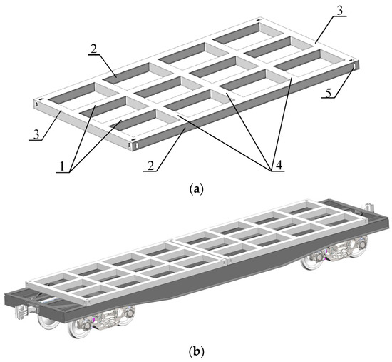
Figure 1.
FLAT RACK removable module: (a) Structural elements of the removable module; (b) removable module on a flat wagon.
The choice of the optimal profiles in terms of the minimal material capacity for the removable module was made by means of the strength calculation with the finite element method in Lira [17,18]. The removable module was studied as a frame system on the hinged fixed supports in the corners. Two diagrams of loading on the module were studied. Diagram I included the vertical loading equally distributed by its components (Figure 2), and Diagram II included the longitudinal loading (Figure 3) on the module.
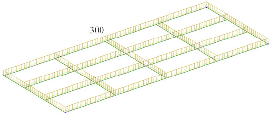
Figure 2.
Design diagram of the module at loading Diagram I (kN).
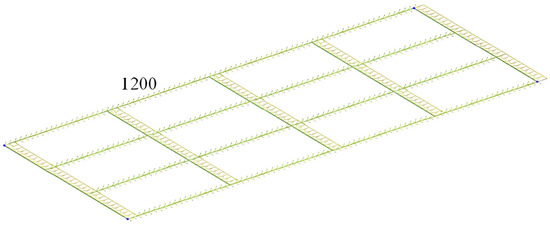
Figure 3.
Design diagram of the module at loading Diagram II (kN).
For Diagram I, it was assumed that the vertical load on the module was 300 kN. The module was fastened in the corners with the fittings.
During the calculation, the diagrams of bending and torque moments on the model components were obtained (Figure 4 and Figure 5).
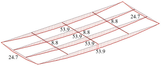
Figure 4.
Diagram of the bending moments on the module (kN·m).
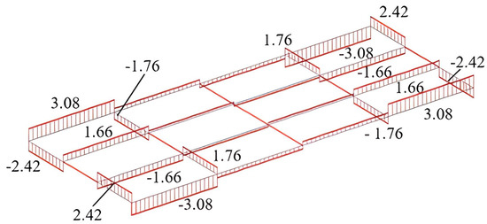
Figure 5.
Diagram of the torque moments on the module (kN·m).
The maximum value of the bending moment was recorded on the main longitudinal beams, and it was amounted to 53.9 kN·m. The maximum torque moment also emerged in the main longitudinal beams on the area between the fittings and the first crossbeam from the end cross beam; it amounted to 3.08 kN·m.
The maximum value of the bending moment was recorded on the main longitudinal beams, and it was amounted to 53.9 kN·m. The maximum torque moment also emerged in the main longitudinal beams on the area between the fittings and the first crossbeam from the end crossbeam; it amounted to 3.08 kN∙m.
Under the longitudinal loading on the module, it underwent compression deformation because it was fastened in the corners. In this case, the maximum value of the longitudinal force emerged in the main longitudinal beams on the area between the fittings and the first crossbeam from the end cross beam, and it amounted to 231 kN (Figure 6).
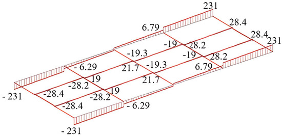
Figure 6.
Diagram of the longitudinal forces (kN).
The maximum bending moment on the removable module emerged in the intermediate crossbeams, and it amounted to 309 kN·m (Figure 3). In the end crossbeams, it amounted to 309 kN·m. The value of the bending moment in the longitudinal beams was 283 kN·m.
The value of the optimal profile in terms of the minimal material capacity for the removable module was determined according to the values of moment and longitudinal force.
When the bending moment affected the removable module, the resistance moment of the module components could be determined by formula [19]:
where M—the bending moment; [σ]—the allowable stresses.
With the longitudinal force on the module, the cross-section of the profile was determined as follows:
where F—the longitudinal force on the module; [σ]—the allowable stresses.
As far as the values of bending moments emerging in the module structure at Diagram I were insignificant, they were neglected for the determination of the profile components.
Taking into account the calculation, the value of the resistance moment for the module components was W = 173.6 cm3. Additionally, the allowable stresses were taken as 0.9σS, where σS was the yield strength of the material. Steel 09C2Cu, widely used for the production of rail vehicles, was used as such a material with a fluidity level of 345 MPa.
In the calculation, the optimal cross-section of the module profile was 7.4 cm2 according to Formula (2).
According to the value of the resistance moment, the profile for the module components was chosen. It was a rectangular tube with a height of 180 mm and a wall thickness of 4.5 mm at a resistance moment of 175.7 cm3 (Figure 7 [20,21]). One meter of the pipe weighted 24.39 kg.
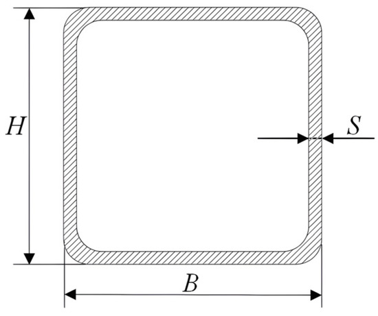
Figure 7.
Cross-section of the rectangular tube: H—height; B—width; S—wall thickness.
Taking into account the profile parameters, the cross section was 32.4 cm2. The cross-section area obtained was higher than that calculated by Formula (2). It should be noted that with these cross-section values, the profile strength would not be provided under the bending moment. Therefore, the profile was chosen by the values obtained by Formula (1).
Taking into account the given profile, the module mass was about 0.88 tons. If necessary, the removable module structure can be supplemented with stops (walls), tying rings, brackets, or other devices for securing the freight.
4. The Determination of the Dynamic Loading on the Removable Module Structure
The loading on the removable module at the operational modes can be reduced through mounting viscoelastic bonds in the fittings [22]. The authors have substantiated this solution with the fact that when the dynamic loading on the removable module (container) exceeds the friction forces between the fittings and the fitting stops, the dynamic loading on the module can considerably exceed the normative values.
The dynamic loading of the removable module placed on a flat wagon during a shunting impact was determined with mathematical modelling. The design model is given in Figure 8. The parameter PM is the forces emerging in the contact areas between the fittings and the fitting stops. The dynamic loading on the removable module was studied in the plane coordinates.
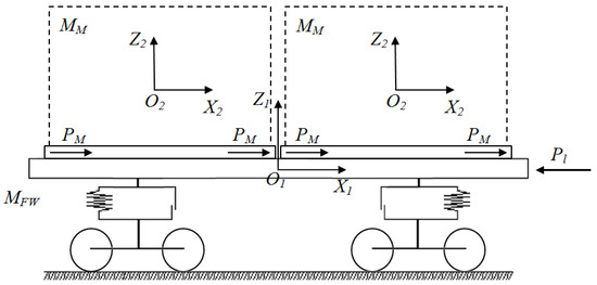
Figure 8.
Design diagram of a flat wagon loaded with two removable modules.
It was assumed in the mathematical model that the removable module was loaded with conditional freight at the maximum allowable loading capacity. The natural displacements of the freight relative to the removable module were neglected. The 13-401M flat wagon was taken as the prototype.
The mathematical model for determination of the dynamic loading of the removable module had the form:
where MFW—the gross mass of the flat wagon;
- Pl—the value of the longitudinal force on the coupler (3.5 MN);
- n—the number of removable modules placed on the flat wagon;
- FFR—the friction force between the fitting stops and the module fittings;
- MM—the mass of the loaded removable module;
- Cf—the rigidity of spring elements in the fittings of the removable module;
- βf—the coefficient of the viscous resistance in the removable module fittings;
- q1, q2—the coordinates corresponding to the displacements of the flat wagon and the removable module relative to the longitudinal axis, respectively.
Mathematical model Equation (3) was solved in MathCad with the Runge-Kutta method [23,24,25] at the initial conditions equalling zero [26,27,28]. The integration of differential equations was carried out with a fixed step. In this case, the built-in function rkfixed (Yo, tn, tk, n, F) was used, where Yo is a vector containing the initial conditions, tn and tk are the initial and final integration variables, respectively, n is the number of steps; F is a character vector.
Mathematical model Equation (3) was solved in the following way:
Whereas .
The generalized accelerations were calculated in the array ddqj,i:
The results of the calculation demonstrated that at the rigidity of a spring element 20 kN/m and the viscous resistance coefficient 30 kN∙s/m, the accelerations to the removable module placed on the flat wagon during a shunting impact were about 34.1 m/s2 (0.34 g) (Figure 9); they did not exceed the allowable values [29,30].
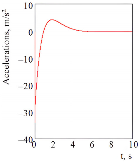
Figure 9.
Accelerations on the removable module.
The mathematical model designed was also verified with computer modelling of the dynamic loading on the removable module placed on the bearing structure of the flat wagon. The spatial models of the bearing structure of the flat wagon and the removable modules were built in SolidWorks. The calculation was made with the finite element method in SolidWorks Simulation [31,32,33]. The finite element model consisted of isoparametric tetrahedrons [34,35]. To determine the optimal number of mesh elements, a graphoanalytical method was used. At the same time, the mesh was of good quality. In the rounding areas (fittings), the mesh was automatically compacted. The number of nodes in the model was 350,869 and the number of elements was 1,045,294. The maximum element size was 80 mm, the minimum element size was 16 mm. Steel 09C2Cu was taken as the structural material. The main technical characteristics of the steel are presented in Table 1.

Table 1.
Basic technical characteristics of Steel 09C2Cu.
The model was secured in the areas of support on the bogies. The calculation included the vertical loading Pv on the removable modules at the full loading capacity (Figure 10).
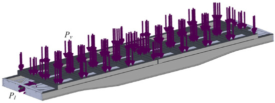
Figure 10.
Design diagram of the bearing structure of a flat wagon loaded with removable modules.
The longitudinal load Pl equalling 3.5 MN was applied to the rear coupler support of the flat car. The fittings of the removable module had the bonds with the rigidity 20 kN/m and the viscous resistance coefficient 30 kN∙s/m. The friction forces between the fittings of the removable modules and the fixed fittings of the flat wagon were neglected.
The results of the calculation are given in Figure 11.
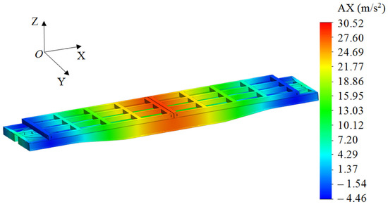
Figure 11.
Design diagram of the bearing structure of a flat wagon loaded with removable modules (AX is the acceleration that acts about the longitudinal axis X).
The maximum accelerations were recorded in the middle part of the flat wagon frame and on the areas where the removable modules were placed behind the middle part; they amounted to 30.5 m/s2. In the end parts the acceleration value was lower and amounted to 4.5 m/s2.
Mathematical model Equation (3) and the design diagram given in Figure 11 were used for the variation calculations and determination of the dependencies between the accelerations to the removable module placed on the flat wagon and the impact force to the coupler (Figure 12). That is, taking into account the variation of the impact force, a spectrum of accelerations acting on the removable module was obtained. At the same time, the reliability of the sample was determined by Student’s t-test.
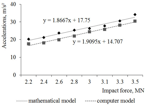
Figure 12.
Dependencies between the accelerations to the removable module placed on a flat wagon and the impact force to the coupler.
The results given in Figure 12 were used for verification of the models of the dynamic loading on the flat wagon with removable modules. The calculation was made with an F-test [36,37,38].
where —the dispersion of adequacy; —the error mean square.
The dispersion of adequacy was calculated by the formula:
where —the design value of the variable obtained in modelling; —the number of freedom degrees.
where N—the number of tests in the planning matrix; q—the number of equation coefficients.
The error mean square was defined by the formula:
where —the dispersion in each line with parallel tests.
It was found that the error mean square was Ssq = 21.64, and the dispersion of adequacy was Sad = 22.1; the actual value of an F-test amounted to Fsq = 1.02, which was lower than its tabular value (Ft = 3.07). Thus, the hypothesis on adequacy was not rejected. Additionally, the maximum difference between the results of mathematic and computer modelling was about 11%, which could happen under an impact force to the coupler of 3.5 MN.
5. The Strength Calculation for the Removable Module
The acceleration value obtained by means of model (3) was included in the strength calculation for the removable module. The strength of the removable module was determined with the finite element method in SolidWorks Simulation.
The design model included the following forces: the vertical loading Pv (Figure 13) to the removable module and the longitudinal loading Pl to the corner fittings.
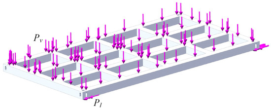
Figure 13.
Design diagram of the removable module.
The removable module was secured in the areas of support on the flat wagon. The finite element model of the removable module was built with isoparametric tetrahedrons. The number of nodes in the model was 9814 and the number of elements was 33,490. The maximum element size was 110 mm and the minimum element size was 22 mm.
The results of the calculation have made it possible to conclude that the maximum equivalent stresses emerge in the contact areas between side longitudinal beams and fittings; they have amounted to 282.2 MPa (Figure 14) and have not exceeded the allowable values.
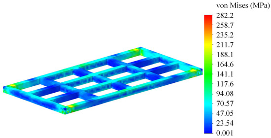
Figure 14.
Stress–strain state of the removable module.
The distribution of the maximum equivalent stresses along the side beams is given in Figure 15. The stresses were taken on the bottom tube wall of the side beam with a step of 600 mm by applying the standard options of SolidWorks Simulation.
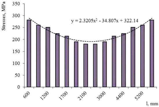
Figure 15.
Distribution of the stresses along the side beam of the removable module (l is the length of the removable module).
The maximum stresses were recorded in the end parts of the beam, and in the middle part they were lower—about 180 MPa.
6. Results and Discussion
The authors of the article propose using the removable module design in order to increase the efficiency of rail transportation. The peculiarity of the removable module is its rectangular-pipe components and elastic-viscous fittings, which will help to reduce the loading of the removable module in operation.
The profile of the removable module is chosen through its calculating as a rod system on hinged fixed supports. The results of the calculation have made it possible to determine the resistance moments of the module cross-sections. With this in mind, a rectangular pipe is selected as the profile of the removable module (Figure 7). Such an intersection is chosen due to the fact that it has a better resistance moment compared to the typical profiles of vehicles: I-beam, channel, lane, etc. For example, in comparison with an I-beam profile of the same height as a rectangular pipe, the resistance moment of the rectangular pipe is almost 20% greater.
To determine the dynamic loads on the removable module, the authors have proposed mathematical model (3). The model’s limitation is the absence of vertical movements of the flat car with removable modules in the vertical plane, that is, jumping oscillations. In addition, the model does not include possible movements of the freight relative to the removable module. This assumption will be taken into account in subsequent studies by the author’s team.
The results of the solution to the mathematical model have made it possible to determine the accelerations to the removable module and include them as a component of the dynamic loading when calculating the structural strength. The acceleration value obtained is 15% lower than that on the removable module, if one takes into account the typical diagram of interaction between fittings and fitting stops and if it is stationary. It should be noted that the model is verified by the F-criterion.
The results of the calculations for the removable module strength have showed that the maximum stresses in the structure are 282.2 MPa and they do not exceed the permissible values (Figure 14). These stresses occur in the areas of interaction between the side beams and the fittings. Additionally, the stress concentration in the corner parts of the module is avoided due to the fact that the fitting is solid, and the longitudinal beam is made of a pipe with a smaller moment of resistance than that of the fitting. Therefore, maximum stresses occur precisely in these areas.
The advantage of this study, in comparison with [8,9], is that the design of the removable module can reduce the dynamic loading on it due to the elastic-viscous bonds in the fittings. Unlike works [10,11,12,13,14], the introduction of flexible bonds is implemented not in the design of traction vehicles, but in a modular-type vehicle intended for transportation by various modes of transport, including international transport. In contrast to work [15], the reduction of the dynamic loading on the removable module is achieved by introducing elastic-viscous bonds in the fittings, rather than elastic-friction ones. In addition, the main load-bearing frame elements of the removable module are made of rectangular pipes, and not of U-shaped profiles with resilient elements inside overlapped by horizontal sheets, which significantly complicates the design, and, accordingly, its maintenance and repair. If compared to [16], the vehicle strength is improved not by introducing materials with improved strength characteristics, but by reducing dynamic loads.
A further area of this study is to determine the feasibility of using lightweight fillers in the removable module components to further reduce its load in operation. In addition, the issues of experimental determination of the strength of the removable module require attention. This study can be carried out using the similarity method in laboratory conditions. It is also planned to consider the determination of tolerances in the manufacture of a removable module. At the same time, it is important to comply with its basic dimensions in accordance with international standards, as well as taking into account the welding seams in the structure. All these issues will be addressed in subsequent studies.
7. Conclusions
- The authors have proposed the FLAT RACK removable module structure and determined the optimal profile for the removable module in terms of the minimal material capacity; this profile is the rectangular tube. In this case, the parameters of the profile are determined by the resistance moment of the cross-sections of the module components. With this profile, the mass of the module is about 0.88 tons. The loading on the removable module at the operational modes can be decreased by means of viscoelastic bonds in the fittings.
- The research included the determination of the dynamic loading on the removable module structure. The results of the calculation demonstrate that if the rigidity of an elastic element is 20 kN/m and the viscous resistance coefficient is 30 kN∙s/m, the accelerations to the removable module placed on the flat car during a shunting impact are about 34.1 m/s2 (0.34 g). The acceleration value obtained is 15% lower than that on the removable module under the typical diagram of interaction between fittings and fitting stops, provided that it is stationary.
- The numerical values of the accelerations to the removable module and their distribution fields are determined by means of computer modelling. The maximum accelerations are recorded in the middle part of the flat wagon and on the areas with the removable modules located behind the middle part; they amount to 30.5 m/s2. The models of the dynamic loading of the removable module are verified with an F-test. It is found that the hypothesis on adequacy is not rejected.
- The removable module is calculated for strength. The maximum equivalent stresses are recorded in the contact areas between the side beams and fittings; they amount to 282.2 MPa and do not exceed the allowable values. In the middle parts of the longitudinal beams, the maximum stresses are about 180 MPa.
- The research conducted can be used by those concerned about designing modern module structures for rail vehicles and enhancing the operational efficiency of rail transportation.
Author Contributions
Conceptualization, J.G. and A.L.; methodology, G.V., S.P. and A.L.; software, A.L.; validation, S.P., A.L. and M.P.; investigation, A.L., M.P. and K.K.; resources, S.P., A.L. and K.K.; writing—original draft preparation, A.L., M.P. and K.K.; writing—review and editing S.P. and J.G.; visualization, G.V., A.L. and K.K.; supervision, S.P. and J.G. All authors have read and agreed to the published version of the manuscript.
Funding
This publication was issued thanks to support from the Cultural and Educational Grant Agency of the Ministry of Education of the Slovakia in the project “Implementation of modern methods of computer and experimental analysis of properties of vehicle components in the education of future vehicle designers” (Project No. KEGA 036ŽU-4/2021). This research was also supported by the Slovakia Research and Development Agency of the Ministry of Education, Science, Research and Sport of the Slovakia in Educational Grant Agency of the Ministry of Education of the Slovakia in the project and VEGA 1/0513/22 “Investigation of the properties of railway brake components in simulated operating conditions on a flywheel brake stand”. The authors also gratefully acknowledge funding from the specific research on “Innovative principles for creating resource-saving structures of railroad cars based on the refined dynamic loads and functionally adaptive flash-concepts”, which was funded from the state budget of Ukraine in 2020.
Institutional Review Board Statement
Not applicable.
Informed Consent Statement
Not applicable.
Data Availability Statement
Not applicable.
Conflicts of Interest
The authors declare no conflict of interest.
References
- Gubarevych, O.; Goolak, S.; Daki, O.; Tryshyn, V. Investigation of Turn-To-Turn Closures of Stator Windings to Improve the Diagnostics System for Induction Motors. Probl. Energy Reg. 2021, 2, 10–24. [Google Scholar] [CrossRef]
- Goolak, S.; Tkachenko, V.; Sapronova, S.; Lukoševičius, V.; Keršys, R.; Makaras, R.; Liubarskyi, B. Synthesis of the Current Controller of the Vector Control System for Asynchronous Traction Drive of Electric Locomotives. Energies 2022, 15, 2374. [Google Scholar] [CrossRef]
- Goolak, S.; Tkachenko, V.; Šťastniak, P.; Sapronova, S.; Liubarskyi, B. Analysis of Control Methods for the Traction Drive of an Alternating Current Electric Locomotive. Symmetry 2022, 14, 150. [Google Scholar] [CrossRef]
- Štastniak, P.; Kurčík, P.; Pavlík, A. Design of a new railway wagon for intermodal transport with the adaptable loading platform. In MATEC Web of Conferences, Proceedings of the Horizons of Railway Transport 2018, 10th Year of International Scientific Conference, Strecno, Slovakia, 11–12 October 2018; EDP Sciences: Paris, France, 2018; Volume 235, p. 00030. [Google Scholar]
- Dižo, J.; Harušinec, J.; Blatnický, M. Computation of modal properties of two types of freight wagon bogie frames using the finite element method. Manuf. Technol. 2018, 18, 208–214. [Google Scholar] [CrossRef]
- Štastniak, P.; Moravčík, M.; Smetanka, L.; Baran, P. Strength investigation of Main Frame in New Track friendly Railway Bogie. Manuf. Technol. 2018, 18, 315–320. [Google Scholar] [CrossRef]
- Dižo, J.; Harušinec, J.; Blatnický, M. Structural analysis of a modified freight wagon bogie frame. In MATEC Web of Conferences, Proceedings of the 18th International Scientific Conference-LOGI 2017, Ceske Budejovice, Czech Republic, 19 October 2017; EDP Sciences: Paris, France, 2017; Volume 134, p. 00010. [Google Scholar]
- Petrukhin, V.M. Device for Arrangement and Fastening of Loads on Platform. Patent Application No. 97105256, 29 October 1997. [Google Scholar]
- Petrukhin, V.M. Unit Load. Utility Model Patent No. 39951 UA. Patent Application No. u200809416, 18 July 2008. Available online: https://sis.ukrpatent.org/en/search/detail/274262/ (accessed on 25 November 2022).
- Fomin, O.; Gerlici, J.; Gorbunov, M.; Vatulia, G.; Lovska, A.; Kravchenko, K. Research into the Strength of an Open Wagon with Double Sidewalls Filled with Aluminium Foam. Materials 2021, 14, 3420. [Google Scholar] [CrossRef]
- Fomin, O.; Gorbunov, M.; Gerlici, J.; Lovska, A.; Kravchenko, K. Dynamics and strength of circular tube open wagons with aluminum foam filled center sills. Materials 2021, 14, 1915. [Google Scholar] [CrossRef]
- Kuczek, T. Application of manufacturing constraints to structural optimization of thin-walled structures. Eng. Optim. 2016, 48, 351–360. [Google Scholar] [CrossRef]
- Płaczek, M.; Wróbel, A.; Olesiejuk, M. Modelling and arrangement of composite panels in modernized freight cars. In MATEC Web of Conferences, Proceedings of the 21st Innovative Manufacturing Engineering & Energy International Conference—IManE&E 2017, Iasi, Romania, 24–27 May 2017; EDP Sciences: Paris, France, 2017; Volume 112, p. 06022. [Google Scholar] [CrossRef]
- Al-Sukhon, A.; ElSayed, M.S.A. Design optimization of hopper cars employing functionally graded honeycomb sandwich panels. Proc. Inst. Mech. Eng. Part F J. Rail Rapid Transit 2022, 236, 920–935. [Google Scholar] [CrossRef]
- Fomin, O.; Gerlici, J.; Vatulia, G.; Lovska, A.; Kravchenko, K. Determination of the Loading of a Flat Rack Container during Operating Modes. Appl. Sci. 2021, 11, 7623. [Google Scholar] [CrossRef]
- Jagadeesh, P.; Puttegowda, M.; Oladijo, O.P.; Lai, C.W.; Gorbatyuk, S.; Matykiewicz, D.; Rangappa, S.M.; Siengchin, S. A comprehensive review on polymer composites in railway applications. Polym. Compos. 2022, 43, 1238–1251. [Google Scholar] [CrossRef]
- Vatulia, G.L.; Petrenko, D.H.; Novikova, M.A. Experimental estimation of load-carrying capacity of circular, square and rectangular CFTS columns. Nauk. Visnyk Natsionalnoho Hirnychoho Universytetu 2017, 6, 97–102. [Google Scholar]
- Glib, V.; Lobiak, A.; Orel, Y. Simulation of performance of circular CFST columns under short-time and long-time load. In MATEC Web of Conferences, Proceedings of the 6th International Scientific Conference “Reliability and Durability of Railway Transport Engineering Structures and Buildings” (Transbud-2017), Kharkiv, Ukraine, 19–21 April 2017; EDP Sciences: Paris, France; Volume 116, p. 02036. [CrossRef]
- Schwabjuk, V.I. Strength of Materials: Textbook; Knowledge: Kiev, Ukraine, 2016; 400p, ISBN 978-617-07-0360-4. [Google Scholar]
- GOST R54157-2010; Steel Shapes Tubes for Metal Structures. Technical Requirements. IPK Standards Publishing: Moscow, Russia, 2012; 92p.
- DSTU 8940:2019; Steel Profile Pipes. Technical Conditions. UkrNDNTS: Kiev, Ukraine, 2021; 22p.
- Lovska, A.; Fomin, O.; Horban, A.; Radkevych, V.; Skok, P.; Skliarenko, I. Investigation of the dynamic loading of a body of passenger cars during transportation by rail ferry. EUREKA Phys. Eng. 2019, 4, 91–100. [Google Scholar] [CrossRef]
- Dudnyk, V.; Sinenko, Y.; Matsyk, M.; Demchenko, Y.; Zhyvotovskyi, R.; Repilo, I.; Zabolotnyi, O.; Simonenko, A.; Pozdniakov, P.; Shyshatskyi, A. Development of a method for training artificial neural networks for intelligent decision support systems. East.-Eur. J. Enterp. Technol. 2020, 32, 37–47. [Google Scholar] [CrossRef]
- Nalapko, O.; Shyshatskyi, A.; Ostapchuk, V.; Mahdi, Q.A.; Zhyvotovskyi, R.; Petruk, S.; Lebed, Y.; Diachenko, S.; Velychko, V.; Poliak, I. Development of a method of adaptive control of military radio network parameters. East.-Eur. J. Enterp. Technol. 2021, 1, 18–32. [Google Scholar] [CrossRef]
- Lovskaya, A. Assessment of dynamic efforts to bodies of wagons at transportation with railway ferries. East.-Eur. J. Enterp. Technol. 2014, 3, 36–41. [Google Scholar] [CrossRef]
- Liu, D.; Liu, H.; Wu, Y.; Zhang, W.; Wang, Y.; Santosh, M. Characterization of geo-material parameters: Gene concept and big data approach in geotechnical engineering. Geosyst. Geoenviron. 2022, 1, 100003. [Google Scholar] [CrossRef]
- Qiang, O.; Ling, Z.; Xuanming, D.; Chenglong, W. Response of Inclined Loaded Pile in Layered Foundation Based on Principle of Minimum Potential Energy. Int. J. Geomech. 2022, 22, 04022090. [Google Scholar]
- Ling, Z.; Qiang, O.; Shuai, Z. Analytical study of the dynamic response of a double-beam model for a geosynthetic-reinforced embankment under traffic loads. Comput. Geotech. 2020, 118, 103330. [Google Scholar]
- DSTU 7598:2014; Freight Wagons. General Requirements for Calculations and Design of New and Modernized Wagons of 1520 mm Track (Non-Self-Propelled). UkrNDNTS: Kiev, Ukraine, 2015; 162p.
- DSTU ISO 1496-1:2013; Freight Containers of the Series 1. Technical Requirements and Test Methods. Part 1, Containers of General Purpose Universal. Ministry of Economy of Ukraine: Kiev, Ukraine, 2014; p. 34.
- Fomin, O.; Lovska, A. Determination of dynamic loading of bearing structures of freight wagons with actual dimensions. East.-Eur. J. Enterp. Technol. 2021, 2, 6–15. [Google Scholar] [CrossRef]
- Fomin, O.; Lovska, A.; Melnychenko, O.; Shpylovyi, I.; Masliyev, V.; Bambura, O.; Klymenko, M. Determination of dynamic load features of tank containers when transported by rail ferry. East.-Eur. J. Enterp. Technol. 2019, 5, 19–26. [Google Scholar] [CrossRef]
- Lovska, A.; Fomin, O.; Píštěk, V.; Kučera, P. Dynamic load and strength determination of carrying structure of wagons transported by ferries. J. Mar. Sci. Eng. 2020, 8, 902. [Google Scholar] [CrossRef]
- Fomin, O.; Lovska, A.; Vaclav, P.; Kucera, P. Substantiation of Improvements for the Bearing Structure of an Open Car to Provide a Higher Security during Rail/Sea Transportation. J. Mar. Sci. Eng. 2021, 9, 873. [Google Scholar] [CrossRef]
- Fomin, O.; Vatulia, G.; Lovska, A. Determination of loads on the body of a boxcar with elastic elements in the center sill. Acta Polytech. 2022, 62, 451–458. [Google Scholar] [CrossRef]
- Kobzar, A.I. Applied Mathematical Statistics; Fizmatlite: Moscow, Russia, 2006; 816p. [Google Scholar]
- Ivchenko, G.I.; Medvedev, Y.I. Mathematical Statistics; LIBROCOM: Moscow, Russia, 2014; 352p. [Google Scholar]
- Rudenko, V.M. Mathematical Statistics; Center of Educational Literature: Kiev, Ukraine, 2012; 304p. [Google Scholar]
Disclaimer/Publisher’s Note: The statements, opinions and data contained in all publications are solely those of the individual author(s) and contributor(s) and not of MDPI and/or the editor(s). MDPI and/or the editor(s) disclaim responsibility for any injury to people or property resulting from any ideas, methods, instructions or products referred to in the content. |
© 2022 by the authors. Licensee MDPI, Basel, Switzerland. This article is an open access article distributed under the terms and conditions of the Creative Commons Attribution (CC BY) license (https://creativecommons.org/licenses/by/4.0/).