Abstract
Based on the vibration control method and energy harvesting principle in the bridge field, this paper proposes a distributed vibration reduction and energy harvesting method for bridges. Firstly, the analytical solutions of the induced electromotive force, output power and magnetic damping generated by a coil in a magnetic field were deduced through an electromagnetic theory analysis. In addition, the structural vibration equation under the magnetic damping was deduced. Then, a new method of joint simulation and modeling analysis of vibration and energy output was proposed. Finally, the structural vibration reduction and energy output power were analyzed and calculated. The main research results are as follows: by calculating the instantaneous power of the energy collection of the designed circuit, the average instantaneous power collected by the design method is 1.093 × 10⁻⁹ W; the initial vibration signal of the target node is obtained through analysis, and the vibration signal of the node before and after applying the electromagnetic damping force is transformed. For the energy analysis, the energy of the acceleration curve before and after the node was calculated to be 3.1048 × 10⁸ and 3.1044 × 10⁸, respectively, and the reduction rate of the node vibration energy was 0.01% and 0.02%, respectively. Thus, the feasibility and vibration reduction effect of the designed bridge distributed vibration reduction and energy harvesting method is verified when the electromagnetic damping force is small. This method can provide new ideas for bridge structure vibration reduction and energy harvesting research and is of great significance to the infrastructure construction and utilization of renewable energy.
1. Introduction
As a pivotal project in the transportation system, bridge structures play an important role in ensuring smooth traffic and maintaining the sustainable and stable development of the national economy. Bridge vibration is a problem that cannot be ignored in the healthy service of bridges. Bridge vibration monitoring and vibration control are indispensable means to improve the service performance of bridges.
Various monitoring systems and wireless sensor networks in the bridge field are becoming more and more popular [1]. The electronic components of monitoring systems or wireless sensor networks need to rely on their own batteries to work continuously. Traditional batteries not only increase the size and weight of sensor devices but are also limited by their working time, replacement environment and replacement cost. Therefore, energy collection from the surrounding environment to solve the problem of power supply has attracted more and more attention. According to the principle of energy conversion, vibration energy collectors are mainly divided into electrostatic type, piezoelectric type [2,3,4,5,6], electromagnetic type [7,8] and magnetostrictive type [9,10].
Miao Shi [11] studied the energy collection of the wind-induced vibration of suspension bridges and designed linear and nonlinear electromagnetic energy collectors, respectively. The numerical simulation results show that a series of tuned mass dampers installed on a bridge can form a system with both vibration reduction and energy collection. Its peak power can reach 1.45 W and 3.63 W, respectively. Byung-Wan. Jo et al. [12] developed a device to extract energy from the vibration of urban infrastructures such as bridges and rails. The actual measurement shows that the average power of the instrument reaches 0.2 μW under an 8 mg acceleration and 14 Hz vibration frequency. Because the wire is wound in a small part of the cylindrical tube, the power generation of the instrument is very small. Soon-Duck Kwon et al. [13] studied the applicability of an electromagnetic generator with repulsive stacked magnets, which is mainly used to extract energy from the vehicle-induced vibration of bridges. The actual test and numerical simulation of the real bridge show that the average power can reach 0.12 mW under an acceleration of 0.25 m/s2 and natural frequency of 4.1 Hz. Iftikhar Ahmad [14] and others developed an electromagnetic energy acquisition device with a membrane magnet suspension system as the key structure. Under 3 g and 27 Hz sinusoidal excitation, the open circuit voltages of a single planar coil and a winding coil of the model reached 15.7 mV and 11.05 mV, respectively. Under the corresponding 3.6 Ω and 1.8 Ω load conditions, the load power reached 1.8 μW and 2.1 μW. Bin Yang et al. [15] designed and manufactured a multi-frequency distributed energy acquisition device consisting of three permanent magnets, three groups of double-layer copper coils and a support beam made of acrylic material. When the vibration amplitude between the magnet and the coil was 14 μm and the gap was 0.4 mm, the maximum output voltage and power corresponding to the first and second vibration modes were 1.38 mV–0.6 μW and 3.2 mV–3.2 μW, respectively.
The magnetostrictive energy collector collects energy based on the magnetostrictive effect of materials. When subjected to an external mechanical vibration force, the magnetization and external magnetic field of a material will change, and an induced electromotive force will be generated in the energy pickup coil. Saber Mohammadi [16] and others developed a beam structure vibration energy collector with a magnetostrictive material and pickup coil winding based on strain energy. The results show that the output power of the collector can reach 9.4 mW under basic excitation. Amr Adly [9] and others conducted experimental research on a magnetostrictive energy acquisition device and proposed a more effective model definition method. Marin A et al. [10] developed a magnetostrictive and electromagnetic combined vibration energy collector, which generates 5.3 mW, 2.57 mW, and 0.27 mW of power respectively when excited by 0.9 g, 0.7 g, and 0.4 g. Mori K et al. [17] designed an adjustable beam magnetostrictive collector based on the Terfenol-D alloy. Toshiyuki Ueno et al. [18] designed a magnetostrictive vibration energy collector containing a Galfenol rod, coil and bias magnetic field. Compared with the traditional piezoelectric cantilever, the collector has better robustness and higher efficiency.
Lei Zuo et al. [19,20] believe that structural vibration control and energy recovery can be achieved by using a Tuned Mass Damper (TMD). They replaced the viscous energy dissipation elements between the TMD and the main system with electromagnetic transducers and optimized the parameters of vibration suppression and energy acquisition using a gradient-based method. Ryan L. Harne et al. [20] modeled and analyzed a distributed electromagnetic oscillator with wide-band damping and concurrent energy acquisition. Wenai Shen et al. [21] investigated the feasibility and effectiveness of synchronous vibration control and energy acquisition using an energy regenerative TMD in high-rise buildings.
There are relatively few studies on bridge vibration control and energy collection and power supply at the same time. Therefore, this research is composed of mainly two aspects: on the one hand, it is concerned with the aspect of bridge vibration control to dissipate energy with the help of control systems; on the other hand, bridge vibration energy collection is studied, and the bridge vibration energy is collected to supply power for sensors.
2. Theoretical Analysis of Distributed Vibration Reduction and Electromagnetic Energy Collection for Bridges
A distributed vibration reduction and energy collection system for bridges was designed in this paper. The schematic diagram is shown in Figure 1. Its core is an array coil permanent magnet structure. In order to realize the sensing function, corresponding sensor elements, a microprocessor, digital-to-analog conversion, a radio frequency module, etc., are also needed, which were not considered in this research. The vibration reduction effect of bridge electromagnetic energy harvesting is closely related to the bridge structure and magnetic field distribution. Combined with the principle of bridge vibration and electromagnetic field distribution, the following analysis was carried out.
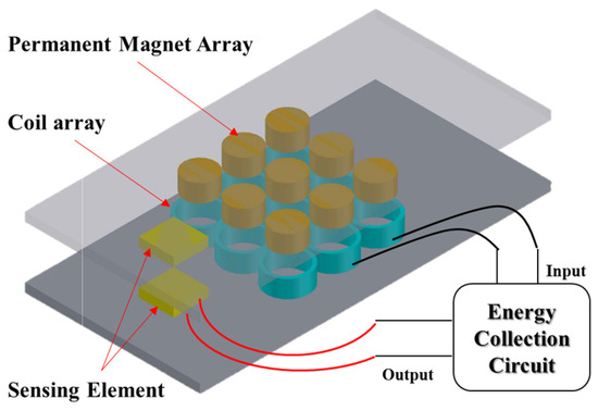
Figure 1.
The system diagram.
The energy of the system comes from the movement of the coil in the permanent magnet magnetic field to cut the magnetic induction line and generate the induced electromotive force, which converts the mechanical energy of the bridge structure vibration into electrical energy. In this process, if the coil forms a loop, an induced current is generated in the coil, and the coil is subjected to an ampere force in the magnetic field of the permanent magnet due to the existence of the induced current. According to the principle of force and reaction force, the coil generates an equal reverse electromagnetic damping force on the structure. According to the conservation of energy, the electromagnetic damping force consumes the vibration mechanical energy and converts it into electrical energy, so the vibration mechanical energy is certainly reduced. The vibration of the structure is weakened to a certain extent, although the amplitude is small. In this paper, the output power is used to characterize the energy collection effect, and the energy value of the displacement/velocity/acceleration time-history curve is used to characterize the vibration control effect.
2.1. Electromotive Force of Magnetic Induction Coil
The calculation diagram of electromotive force is shown in Figure 2. The permanent magnet reciprocates in the vertical direction. The coil cuts the horizontal magnetic induction line. Therefore, the electromotive force is independent of the vertical magnetic field component Bz. In the xoz plane, it is only related to the horizontal component Bx. The magnetic field and coil are axisymmetric, so the magnetic force on a single coil can be calculated.
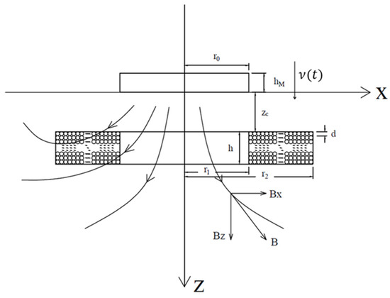
Figure 2.
Schematic diagram of magnetic field and coil.
The electromotive force generated by a single-turn coil is expressed by the following equation:
where v(t) is the vertical vibration velocity of the magnet, Bx is the radial component of the field intensity at any point in space, rj is the radius of the jth coil from inside to outside, rj = r1 + (d/2) + (j − 1)d, r1 is the radius of the innermost coil, and d is the conductor diameter. zi is the distance from the ith layer coil to the bottom of the permanent magnet, and for zi = zc + (d/2) + (i − 1)d, zc is the vertical distance from the coil top to the permanent magnet bottom. xj is the coordinates in the horizontal direction of the central water of the jth coil, and xj = rj. The total induced electromotive force on the coil is as follows:
where m is the number of vertical layers of coil, m = (h/d), h is the total coil thickness, n is the number of horizontal layers of coil, n = (r2 − r1)/d, and r2 is the outer diameter of the coil.
Let . The value of ku is only related to the magnetic field distribution and the relative space position between the coil and the magnet. ku is considered to be the electromechanical coupling coefficient reflecting the relationship between the motion speed of the magnet and the induced electromotive force of the coil. The Equation (2) can be written as
2.2. Coil Output Power and Electromagnetic Damping Force
The fundamental frequency of the actual bridge structure vibration is generally a few hertz to a dozen hertz, which belongs to low-frequency vibration. Therefore, the frequency of the vibration signal transmitted to the permanent magnet is mainly low-frequency. The inductance of the coil is far less than the internal resistance of the coil, and the inductance can be ignored. Assuming that the coil resistance is R0 and the external resistance is R1, regardless of the inductance and capacitive reactance of the external load, the current and output power of the energy acquisition circuit can be expressed as
If we input the electromotive force ε into Equation (4), then the output power P can be expressed as
Therefore, when the coil internal resistance and external resistance are fixed, the greater the electromechanical coupling coefficient, and the greater the output power.
The magnitude of the electromagnetic damping force Fuv provided by a single group of coils is equal to the Ampere force FI in the opposite direction, which can be represented as follows:
where is the current vector, is the Magnetic field vector and I is the current scalar.
In general, the coil internal resistance R0 is a fixed value. From Equations (5) and (6), it can be seen that as the load resistance increases, the output power and electromagnetic damping cannot reach the maximum at the same time.
The output power and the electromagnetic damping force were normalized and expressed as
As shown in Figure 3, the energy output and electromagnetic damping could not reach the maximum at the same time. The calculation of the electromagnetic damping force can provide a reference for the finite element analysis of structural vibration. In order to consider both the output power and the electromagnetic damping force, the optimum ratio of the external resistance to the internal resistance of the coil was 1/3. The value of each parameter was 75% of the maximum. If the electromagnetic damping force is maximized, the resistance value of the external load is zero, i.e., the coil is closed:
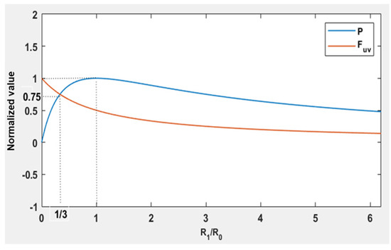
Figure 3.
Change in normalized value with load.
If the output power was maximized, the electromagnetic damping force was only 50% of the maximum value, as
2.3. Calculation of Structural Vibration
If the bridge structure is considered as a single degree of freedom and subjected to harmonic load, the vibration equation can be expressed as
where m is the mass, u(t) is the displacement, c is the structural damping coefficient, k is the stiffness coefficient and FP is the external load.
For the convenience of calculation, the electromechanical coupling coefficient was simplified as a fixed value. It was considered that the electromechanical coupling coefficient was unchanged within the range of coil motion. In this way, the electromagnetic damping becomes a viscous damping only related to speed, so it can be written together with the original viscous damping:
Based on the damped steady state, the dynamic magnification factor β is
where μ is the ratio of load frequency to natural frequency, ζ is the equivalent viscous damping ratio.
Therefore, the electromagnetic damping force will increase the equivalent damping ratio and decrease the dynamic amplification coefficient so as to reduce the dynamic displacement and control the vibration.
The actual situation is much more complex, as the dynamic magnification factor of each degree of freedom is not the same, and the application of control force at one point may cause the strengthening of vibration at other points. Therefore, this paper focused on the vibration of the corresponding point of the coil permanent magnet structure. After obtaining the vibration response of the point, the damping effect is characterized by calculating the energy value. When a homogeneous beam with a uniform cross-section is calculated with an infinite degree of freedom, the dynamic equation of the beam is expressed as follows:
where E is the elastic modulus, I is the moment of inertia, u(x,t) is the displacement of mass point vibration, m is the mass per unit length of the fixed beam and Fp(x,t) is the applied loads of varying magnitude with location and time.
Assuming that the electromechanical coupling coefficient at each coil position was almost the same with the displacement distribution and each given value, then Fuv(xi,t) could be expressed as follows:
In the energy acquisition stage, the external resistance is a dynamic variable, which makes the calculation of the electromagnetic damping force very complex. Therefore, it needs to be directly converted into the current value, as follows:
Each current can be obtained by a circuit simulation and solution through the electromotive force at the corresponding coil. In the closed stage of the coil, the electromagnetic damping force can be directly calculated as follows:
When calculating the magnetoresistive force, the obtained initial dynamic response of the control point without forming a closed loop can be substituted into the trial calculation. When the calculated electromagnetic damping force is very small relative to the applied load, it indicates that the vibration reduction effect is not obvious. The calculated electromagnetic damping force can be input into the finite element software to calculate the dynamic response. If we want to obtain more accurate results, we can carry out an iterative calculation, that is, use the first calculated electromagnetic damping force to calculate the second node dynamic response. Then, we use the second dynamic response to calculate the second electromagnetic damping force and then use the second electromagnetic damping force to calculate the third dynamic response, in a continuous iterative calculation. When the difference between the last two dynamic responses is less than the convergence condition, the iteration terminates, and the dynamic response is the final dynamic response. If the calculated damping force relative to the external load cannot be ignored, then this approximate calculation is no longer applicable and will produce a very large error, and it is only through experiments that the dynamic response can be determined. In this study, the dynamic response changed minimally, and no iterative calculation was carried out.
3. Joint Simulation Process and Modelling of Vibration and Circuit
3.1. Simulation Process
This research used the general-purpose finite element software ABAQUS (version 6.14-5, 3DEXPERIENCE Company, Waltham, MA, USA), the circuit design and simulation software Tina-TI (version 9.3.30.248, Texas Instruments, Dallas, TX, USA) and the programming and numeric computing platform MATLAB (version 2020b, MathWorks. Inc., Natick, MA, USA) for the numerical modeling and simulation. The co-simulation of the structural vibration simulation and electromagnetic energy harvesting process was realized through user-defined programs. The simulation process is shown in Figure 4. Firstly, the vibration signal of the bridge under a moving load was obtained by using the finite element model of the ABAQUS software. Then, the program for calculating the electromechanical coupling coefficient of the magnetic induction coil was compiled on the MATLAB software platform and the electromotive force of the magnetic induction coil was obtained by inputting the vibration data extracted from ABAQUS. Then, the calculated electromotive force data was imported into the Tina-TI software for the circuit simulation to obtain the current signal in the coil. Finally, according to the current signal to calculate the electromagnetic damping force, the calculated magnetic damping as a load was inputted into the ABAQUS finite element model and then simulated to obtain the vibration signal and then extracted, repeating the above steps until convergence.
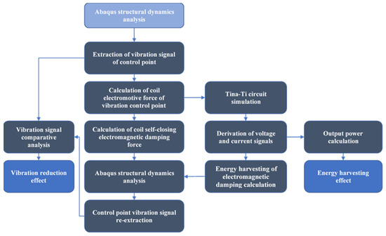
Figure 4.
Combined numerical simulation and circuit simulation flow.
3.2. Finite Element Simulation of Vibration Signal
ABAQUS software was selected for the bridge vibration analysis. The main process was as follows: Firstly, the bridge model was simplified as a rectangular flat plate, and the vehicle movement was simplified as a moving load on the beam plane. The length, width and height of the model were 600 mm, 100 mm and 2 mm, respectively. The total number of the elements was 6902. The element type was the 8-node linear brick (C3D8R). The material properties of the model are shown in Table 1. Secondly, three-dimensional deformable solid components were selected for the fixed beam, and the bottoms of both ends were fixed as shown in Figure 5a. The constraint length on each side was 30 mm. Finally, the DLOAD subroutine was used to load the bridge. This subprogram is suitable for dynamic implicit calculations. On the upper surface of the model, a uniformly distributed moving load was applied. As shown in Figure 5b, the loading area was x × z = 2 mm × 10 mm and the load moved uniformly along the central axis. The load value was 0.0147 MPa and the moving speed of the load was 0.5 m/s.

Table 1.
The material properties of the model.
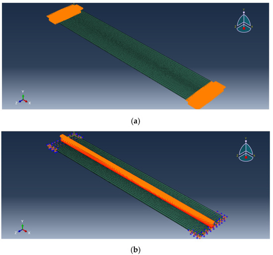
Figure 5.
Fixed-beam model. (a) The boundary conditions. (b) The load conditions.
An implicit dynamic analysis step was set after the initial analysis step, and the time parameters of the analysis step were calculated from the length and moving speed of the beam. The incremental step adopted a fixed incremental step, and the time of a single incremental step was selected as 0.002 s, that is, 600 calculations were performed in one analysis step. The algorithm of the numerical modeling is similar to the authors’ previous studies [22,23,24,25], and the reliability of the model has been proved. After calculation, the vertical vibration displacement nephogram of the fixed beam at 0.3 s, 0.6 s and 0.9 s was obtained as shown in Figure 6, Figure 7 and Figure 8.
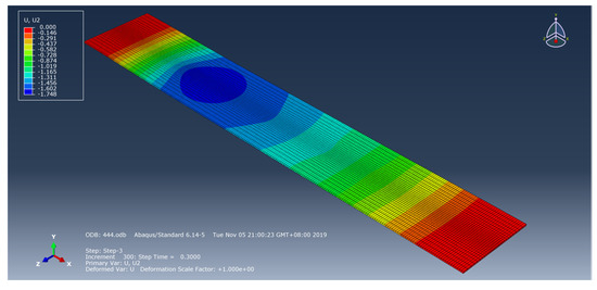
Figure 6.
Vertical vibration displacement map diagram at 0.3 s.
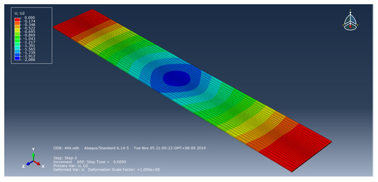
Figure 7.
Vertical vibration displacement map diagram at 0.6 s.
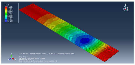
Figure 8.
Vertical vibration displacement map diagram at 0.9 s.
3.3. Design of Array Energy Acquisition Circuit
In this energy acquisition system, the energy of the vibration generator came directly from the relative motion between the coil and the permanent magnet fixed on the bridge. The power output of a single generator is very small; however, it has good scalability and can be expanded from multiple generators into an array form, as shown in Figure 1. In this research, four groups of generators constituted the 2 × 2 array. These generators were connected in a series to increase the output voltage.
Tina-TI software was used for the circuit design and simulation. In the circuit design, the electromotive force generated by the coil was equivalent to the series connection of a voltage generator and a resistance, and the resistance in the series is used to represent the internal resistance of the coil. Since the electromotive force signal generated by the coil was an alternating current, a voltage source and battery pack were used as the signal source. The common full bridge rectifier was adopted, and the large capacitor was used as the energy storage element. A voltmeter was set at both ends of the capacitor, and the voltmeter can also be replaced by an oscilloscope.
Each coil voltage signal in the array was rectified first and then connected in a series to both ends of the capacitor. The designed circuit is shown in Figure 9. The function of the switch was to ensure that the coil could be closed after the capacitor was charged (the voltage will not change). At this time, the external resistance is zero, the electromagnetic damping force is at a maximum and the system will work with the best damping effect. Through calculation, it can be concluded that the coil internal resistance in the system energy acquisition circuit simulation is 15.45 Ω. The model of the diode is 1N1183 and the energy storage capacitor is 1 μF.
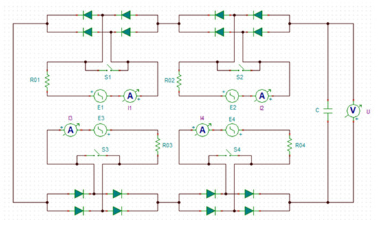
Figure 9.
State-switched array energy harvesting circuit.
4. Results and Discussion
4.1. Vibration Signal Extraction and Electromotive Force Calculation
The displacement, velocity and acceleration time-history curves of the three nodes (node 1, node 2 and node 3) that were in the middle of the loading position at 0.3 s, 0.6 s and 0.9 s were recorded, as shown in Figure 10, Figure 11 and Figure 12. The location of node 1 was x = 161 mm, y = 2 mm, z = 51 mm. The location of node 2 was x = 300 mm, y = 2 mm, z = 51 mm. The location of node 3 was x = 441 mm, y = 2 mm, z = 51 mm.
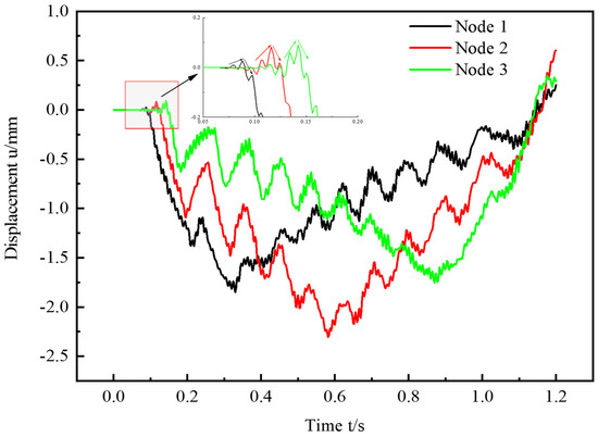
Figure 10.
Node displacement time-history curve.
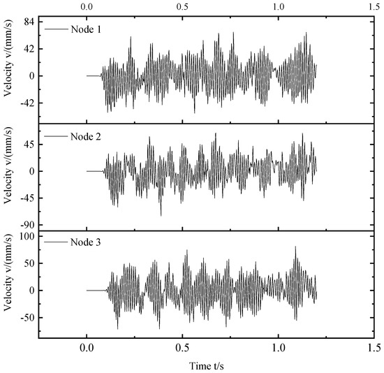
Figure 11.
Node velocity time-history curve.
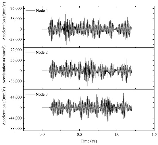
Figure 12.
Node acceleration time-history curve.
It can be seen from the node displacement curve in Figure 10 that the node displacement of the fixed beam includes static displacement and dynamic displacement. When the load was directly above node 2, the static displacement peak appeared, and the dynamic displacement fluctuated within a smaller range on the basis of the static displacement. It can be seen from Figure 10 that the fluctuation of the total displacement was very small, basically between −2.5 mm and 0.5 mm. Therefore, when a fixed value is selected for the electromechanical coupling coefficient ku, the error will be very small.
As shown in Figure 11 and Figure 12, from the velocity and acceleration curves, it can be seen that when the load passed over the node, the vibration frequency changed greatly, and the velocity and acceleration fluctuation also increased to a certain extent.
The selected coil sizes were height h = 10 mm, inner diameter r1 = 10 mm, outer diameter r2 = 12 mm and wire diameter d = 0.22 mm, and the permanent magnet sizes were height hM = 10 mm and radius r0 = 9 mm. The relationship between the calculated electromechanical coupling coefficient ku and zc is shown in Figure 13.
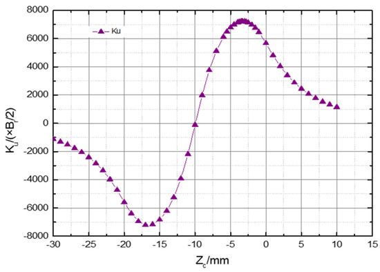
Figure 13.
Variation of electromechanical coupling coefficient with zc.
If a group of generator arrays is placed at the position of each node, the electromotive force at each coil of the bridge distributed damping and energy acquisition system can be calculated according to the maximum electromechanical coupling coefficient and the velocity time series of each point obtained by a finite element simulation, as shown in Figure 14.
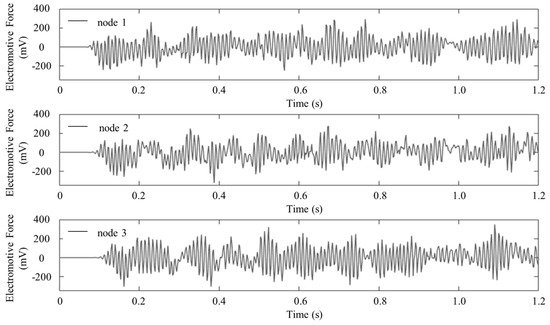
Figure 14.
The coil electromotive force at the nodes.
4.2. Simulation Analysis of Energy Harvesting Circuit
Assuming that the generator was installed in the middle of the span, the energy collection analysis was carried out. In the energy harvesting phase, the four coil closing switches of the acquisition circuit were disconnected, and the calculated value of the electromotive force was input into the four voltage generators. The simulation results are shown in Figure 15. The output voltage of each coil is E1, E2, E3, E4. The output current of each coil is I1, I2, I3, I4. The input current of the storage capacitor is I and the voltage of the storage capacitor is U.
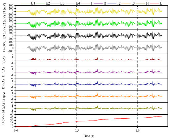
Figure 15.
Array energy harvesting circuit simulation.
It can be seen from Figure 15 that the voltage of the capacitor increased gradually. The alternating current signal in each coil was always at a small value, indicating that the voltage dropped on the internal resistance was very small. The voltage of the energy storage capacitor was also much higher than that of a single rectifier circuit, indicating that the system had a good boost function and energy collection effect. The voltage on the capacitor was much smaller than the input signal.
The instantaneous power of the circuit energy collection was obtained by multiplying the voltage and current values of the capacitor. The calculated instantaneous power is shown in Figure 16, and the average power is 1.093 × 10⁻⁹ W. Based on the current value in each coil, the damping force provided by each coil in the system energy acquisition phase can be calculated, as shown in Figure 17.
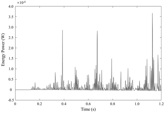
Figure 16.
Energy harvesting power.
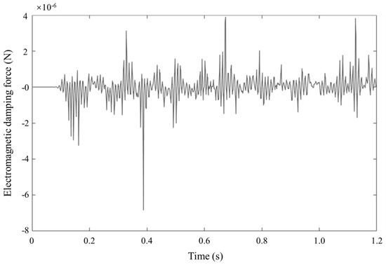
Figure 17.
Coil electromagnetic damping force during the energy harvesting.
If the four coil closing switches are closed, the output power is 0. At this time, the array circuit of the system becomes four independent circuits, and the electromagnetic damping force of a single coil can be directly calculated. As shown in Figure 18, the current in the circuit increased significantly, and the electromagnetic damping force was significantly enhanced. Compared with the applied moving surface load, the damping force cannot be ignored, so the approximate calculation is no longer applicable.
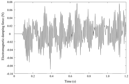
Figure 18.
The coil electromagnetic damping without the energy harvesting.
4.3. Finite Element Simulation Analysis of System Vibration Reduction
According to the previous theoretical analysis, the electromagnetic damping force was calculated for the vibration reduction analysis. Two kinds of electromagnetic damping force were obtained through the circuit simulation. Because the electromagnetic damping force was too large when the coil closed the switch, which would lead to unreliable results, the total electromagnetic damping force (four times the damping force of a single coil) during the energy acquisition was imported into ABAQUS for calculation. The concentrated load applied at a node in the middle span area at the bottom of the beam is shown in Figure 19.
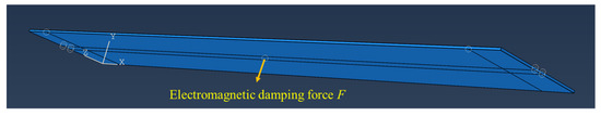
Figure 19.
Schematic diagram of electromagnetic damping force loading.
After the ABAQUS analysis, the vibration curve of a node in the middle span was extracted again. The comparison between the two acceleration and velocity curves is shown in Figure 20 and Figure 21. The signals of the acceleration and velocity were irregular. There was no great difference between the vibration signals before and after the electromagnetic damping force was applied. In this paper, the effect of magnetic damping was evaluated by the signal energy that was time integral of signal squared over a period of time [26]. The energy of the aperiodic signal can be expressed as follows:
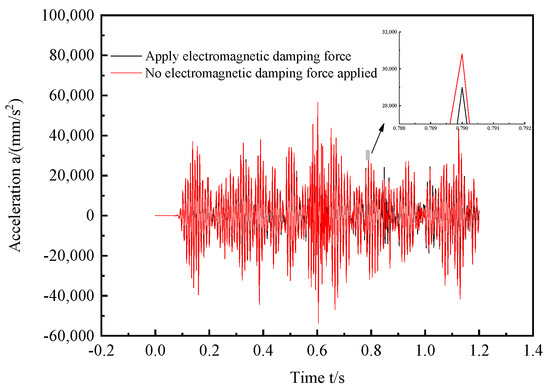
Figure 20.
Acceleration comparison.
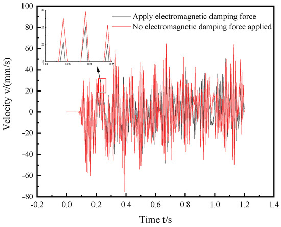
Figure 21.
Speed comparison.
The acceleration signal energies of the node before and after magnetic damping were 3.1048 × 10⁸ and 3.1044 × 10⁸, respectively. The velocity signal energies of the node before and after magnetic damping were 5.9764 × 10² and 5.9750 × 10², respectively, and the reduction rates of the vibration energy of the node of the acceleration and velocity curves were 0.01% and 0.02%, which verifies the vibration reduction effect of the bridge distributed vibration reduction and energy acquisition system.
5. Conclusions
In this research, a bridge vibration reduction technology was proposed using a joint simulation method and energy harvesting. The main results are as follows:
- Through the theoretical analysis, the calculation formulas of the electromotive force, output power and maximum electromagnetic damping force of the energy acquisition circuit were obtained.
- By programming MATLAB, based on the study of the composition of the energy acquisition circuit, the corresponding array energy acquisition circuit was designed according to the structure of the array coil permanent magnet. By calculating the instantaneous power of the energy collection of the design circuit, the average instantaneous power collected by the design method was 1.093 × 10⁻⁹ W.
- The initial vibration signal of the target node was obtained through analysis. The vibration signals of the node before and after the electromagnetic damping were obtained through a joint simulation. The acceleration signal energies before and after energy harvesting were calculated to be 3.1048 × 10⁸ and 3.1044 × 10⁸, and the reduction rate of the vibration energy before and after the node was 0.01%. The velocity signal energies before and after energy harvesting were 5.9724 × 10² and 5.9750 × 10², and the reduction rate of the vibration energy before and after the node was 0.02%.
Based on the array coil permanent magnet structure and the energy acquisition circuit, the system realized the distributed bridge vibration energy acquisition. At the same time, by adjusting the load of the circuit, it has the function of vibration control in different degrees, which provides a new idea for vibration reduction research and the energy collection of civil structures such as bridges.
Author Contributions
Conceptualization, H.Y.; formal analysis, Q.C.; funding acquisition, P.L. and L.W.; project administration, H.Y.; resources, H.L.; supervision, L.W.; validation, S.-H.Y.; writing—original draft, H.Y. and H.C.; writing—review and editing, H.Y., H.C., S.-H.Y. and P.L. All authors have read and agreed to the published version of the manuscript.
Funding
This work was supported by the Fundamental Research Funds of the Central Universities, China (No. FRF-TP-18-048A1) and the Deutsche Forschungsgemeinschaft (DFG, German Research Foundation)-SFB/TRR 339, Project-ID 453596084.
Institutional Review Board Statement
Not applicable.
Informed Consent Statement
Not applicable.
Data Availability Statement
Not applicable.
Acknowledgments
The authors would like to express their thanks to everyone who offered help in the experiments and in the creation of the paper. A special thanks to Kang Zhao and Jianfeng Li for their help in the process of revising the manuscript.
Conflicts of Interest
The authors declare no conflict of interest.
References
- Tong, X.; Hou, Y.; Dong, Y.; Zhang, Y.; Yang, H.; Qian, Z. Research and Development of a Wireless Self-Powered Sensing Device Based on Bridge Vibration Energy Collection. Sensors 2021, 21, 8319. [Google Scholar] [CrossRef] [PubMed]
- Peigney, M.; Siegert, D. Piezoelectric energy harvesting from traffic-induced bridge vibrations. Smart Mater. Struct. 2013, 22, 095019. [Google Scholar] [CrossRef]
- McEvoy, T.; Dierks, E.; Weaver, J.; Inamdar, S.; Zimowski, K.; Wood, K.L.; Crawford, R.H.; Jensen, D. Developing innovative energy harvesting approaches for infrastructure health monitoring systems. In Proceedings of the 37th Design Automation Conference, Parts A and B, Washington, DC, USA, 28–31 August 2011. [Google Scholar]
- Rhimi, M.; Lajnef, N. Tunable energy harvesting from ambient vibrations in civil structures. J. Energy Eng. 2012, 138, 185–193. [Google Scholar] [CrossRef]
- Wang, H.; Tang, L. Modeling and experiment of bistable two-degree-of-freedom energy harvester with magnetic coupling. Mech. Syst. Signal Process. 2017, 86, 29–39. [Google Scholar] [CrossRef]
- Zhang, Y.; Cai, C.S.; Zhang, W. Experimental study of a multi-impact energy harvester under low frequency excitations. Smart Mater. Struct. 2014, 23, 055002. [Google Scholar] [CrossRef]
- Williams, C.B.; Yates, R.B. Analysis of a micro-electric generator for microsystems. Sens. Actuators A Phys. 1996, 52, 8–11. [Google Scholar] [CrossRef]
- Wang, L.; Yuan, F.G. Vibration energy harvesting by magnetostrictive material. Smart Mater. Struct. 2008, 17, 45009–45014. [Google Scholar] [CrossRef]
- Adly, A.; Davino, D.; Giustiniani, A.; Visone, C. Experimental tests of a magnetostrictive energy harvesting device and its modeling. J. Appl. Phys. 2010, 107, 09A935. [Google Scholar] [CrossRef]
- Marin, A.; Tadesse, Y.; Priya, S. Multi-mechanism non-linear vibration harvester combining inductive and magnetostrictive mechanisms. Integr. Ferroelectr. 2013, 148, 27–52. [Google Scholar] [CrossRef]
- Miao, S. Energy Harvesting from Wind-Induced Vibration of Suspension Bridges. Master’s Thesis, Nanyang Technological University, Singapore, 2012. [Google Scholar]
- Jo, B.W.; Lee, Y.S.; Yun, G.W.; Park, C.; Kim, J.W. Vibration-induced energy harvesting for green technology. In Proceedings of the 4th International Conference on Chemical, Environment and Civil Engineering (ICCECE), Manila, Philippines, 17–18 November 2012. [Google Scholar]
- Kwon, S.D.; Park, J.; Law, K. Electromagnetic energy harvester with repulsively stacked multilayer magnets for low frequency vibrations. Smart Mater. Struct. 2013, 22, 055007. [Google Scholar] [CrossRef]
- Ahmad, I.; Khan, F.U. Vibration-based electromagnetic type energy harvester for bridge monitoring sensor application. In Proceedings of the 10th International Conference on Emerging Technologies (ICET), Islamabad, Pakistan, 8–9 December 2014. [Google Scholar]
- Yang, B.; Lee, C.; Xiang, W.; Xie, J.; He, J.H.; Kotlanka, R.K.; Low, S.P.; Feng, H. Electromagnetic energy harvesting from vibrations of multiple frequencies. J. Micromech. Microeng. 2009, 19, 035001. [Google Scholar] [CrossRef]
- Mohammadi, S.; Esfandiari, A. Magnetostrictive vibration energy harvesting using strain energy method. Energy 2015, 81, 519–525. [Google Scholar] [CrossRef]
- Mori, K.; Horibe, T.; Ishikawa, S.; Shindo, Y.; Narita, F. Characteristics of vibration energy harvesting using giant magnetostrictive cantilevers with resonant tuning. Smart Mater. Struct. 2015, 24, 125032. [Google Scholar] [CrossRef]
- Ueno, T.; Yamada, S. Performance of energy harvester using Iron-Gallium alloy in Free Vibration. IEEE Trans. Magn. 2011, 47, 2407–2409. [Google Scholar] [CrossRef]
- Zuo, L. Effective and robust vibration control using series multiple tuned-mass dampers. J. Vib. Acoust. 2009, 131, 031003. [Google Scholar] [CrossRef]
- Ni, T.; Zuo, L.; Kareem, A. Assessment of energy potential and vibration mitigation of regenerative tuned mass dampers on wind excited tall buildings. In Proceedings of the ASME 2011 International Design Engineering Technical Conferences and Computers and Information in Engineering Conference, Washington, DC, USA, 28–31 August 2011. [Google Scholar]
- Harne, R.L. Modeling and analysis of distributed electromagnetic oscillators for broadband vibration attenuation and concurrent energy harvesting. Appl. Math. Model. 2013, 37, 4360–4370. [Google Scholar] [CrossRef]
- Liu, P.; Zhao, Q.; Yang, H.; Wang, D.; Oeser, M.; Wang, L.; Tan, Y. Numerical study on influence of piezoelectric energy harvester on asphalt pavement structural responses. J. Mater. Civ. Eng. 2019, 31, 04019008. [Google Scholar] [CrossRef]
- Liu, P.; Wang, D.; Otto, F.; Oeser, M. Application of semi-analytical finite element method on analyzing bearing capacity of asphalt pavements under moving loads. Front. Struct. Civ. Eng. 2018, 12, 215–221. [Google Scholar] [CrossRef]
- Du, C.; Liu, P.; Jin, C.; Yang, H.; Li, C.; Jiang, G.; Oeser, M. Evaluation of the piezoelectric and mechanical behaviors of asphalt pavements embedded with a piezoelectric energy harvester based on multiscale finite element simulations. Constr. Build. Mater. 2022, 333, 127438. [Google Scholar] [CrossRef]
- Yang, H.; Zhao, Q.; Guo, X.; Zhang, W.; Liu, P.; Wang, L. Numerical analysis of signal response characteristic of piezoelectric energy harvesters embedded in pavement. Materials 2020, 13, 2770. [Google Scholar] [CrossRef] [PubMed]
- Oppenheim, A.V.; Willsky, A.S.; Nawab, S.H. Signals and Systems, 2nd ed.; Prentice-Hall: Upper Saddle River, NJ, USA, 1996; pp. 5–7. [Google Scholar]


Disclaimer/Publisher’s Note: The statements, opinions and data contained in all publications are solely those of the individual author(s) and contributor(s) and not of MDPI and/or the editor(s). MDPI and/or the editor(s) disclaim responsibility for any injury to people or property resulting from any ideas, methods, instructions or products referred to in the content. |
© 2022 by the authors. Licensee MDPI, Basel, Switzerland. This article is an open access article distributed under the terms and conditions of the Creative Commons Attribution (CC BY) license (https://creativecommons.org/licenses/by/4.0/).