Article

Numerical Investigation on the Flow-Induced Vibration Characteristics of Fire Turbopump with the Turbine-Pump Structure

1
School of Energy and Power, Jiangsu University of Science and Technology, Zhenjiang 212100, China
2
Tianjin Navigation Instruments Research Institute, Tianjin 300131, China
3
Research Center of Fluid Machinery Engineering and Technology, Jiangsu University, Zhenjiang 212013, China
*
Author to whom correspondence should be addressed.
Appl. Sci. 2022, 12(9), 4650; https://doi.org/10.3390/app12094650
Submission received: 25 March 2022 / Revised: 29 April 2022 / Accepted: 4 May 2022 / Published: 6 May 2022

Abstract

:
The vibration characteristics induced by radial hydraulic force on the fire turbopump have been investigated by numerical simulations in this paper. The numerical model was validated with corresponding experimental measurements. The turbopump has the special structure with two hydraulic machineries of a turbine and a pump. The hydraulic force characteristics on the separate turbine and the separate pump were first studied. There is one period in the force variation for one cycle of impeller rotation, and pressure fluctuations are observed in 15 times and 30 times the shaft rotating frequency of the turbine. Meanwhile, there are five periods in the force fluctuation in one full working cycle, and obvious fluctuation amplitudes on 5 times, 10 times and 15 times the shaft rotating frequency of the pump are found. Then, the coupled effect of force fluctuations on the turbine and pump was explored. For the turbopump, the periodicity of force fluctuation in the time domain and force characteristics in the frequency domain are dominated by pump structure. The hydraulic force fluctuation on the impeller is enhanced, while that on the housing is damped by counteracting the forces between turbine suction and pump volute.

1. Introduction

The fire turbopump has the special structure with two hydraulic machineries of a turbine and a pump in Figure 1, and plays an important role in supplying the natural water source for handling the fire. When its turbine section is driven by the circulating water from the finite-volume tank of a fire brigade vehicle, its pump section starts to supply continuously natural water to the fire ground. The turbine is hit by the power water during the operating period, which causes different-extent vibrations affecting the steady operation of the pump because of the turbopump structure. Meanwhile, the natural water delivered in the pump is controlled by pump structure and operation condition, and its reaction also results in pump vibration. Due to the special structure of fire turbopump, these flow-induced vibrations are enhanced by the coupled effects of hydraulic forces on the turbine and pump to cause the inconsistent fire-water supply to influence negatively on handling the fire.
Turbopump was invented to draw water from the Kushk River to irrigate farmland by the former Soviet Union in 1922 [1]. Due to its lower energy consumption, the turbopump was widely applied in agricultural irrigation with using the water from the streams and rivers by China in 1970s. The Fujian Research Institute of Mechanics [2,3] studied the design calculation, manufacture and applied research for the turbopump. This turbopump is usually installed on the river or stream with a big vertical drop, such as the river dam in a mountainous region, rapids of the river, tidal areas, etc. The water from the upstream drives the turbine, and then the pump draws the water from downstream to irrigate the farmland. Recently, with the fire supply equipment innovating constantly, the turbopump is introduced to be applied in fire-fighting. The fire turbopump belongs to the micro turbopump, due to its length of 60 mm or so; so its design and application are different than the irrigation turbopump. Some studies on the fire turbopump were conducted by our previous research and revealed the design calculation and stability analysis of the fire turbopump [4,5]. Nevertheless, little research has been conducted for the flow-induced vibration characteristics of the fire turbopump with considering the coupled effects of turbine section and pump section.
The turbine vibration is produced when the water impacts on the volute and impeller. The large radial hydraulic force is generated on the turbine because of the asymmetric structure of volute and rotating impeller, and this force was proved to be the main factor producing the vibration [6,7]. Some unsteady flows have important effects on generating the hydraulic force, such as the non-uniform flow in the volute, two flow-related factors and pressure fluctuations in the impeller passage [8]. Some numerical studies have been conducted to explore unsteady flow characteristics in the impeller and volute [9,10,11]. The radial hydraulic force changes with the radial impeller-volute gap varying, due to the rotor–stator interaction. This force under the design flow condition is different from that under the off-design conditions, and its frequency was proved to be consistent with the impeller rotating frequency.
As for the pump, the internal flow field is determined by pump structure and operation condition. The pressure fluctuation in the flow channel is formed to induce the unit vibration, due to some different types of unsteady phenomena such as flow separation, vortex shedding, rotor–stator interaction, etc. [12]. The impeller–volute interaction is dominant in the generation of the pressure fluctuation in the hydraulic machinery [13]. This fluctuation was measured on the rotating impeller with a high speed pressure sensor; the result revealed that the pressure variations on the blades were closely related to the static pressures in the volute [14,15]. Moreover, the frequency of pressure fluctuation was explored, and it is proven that dominant frequencies are blade passing frequency and its integer harmonics [16,17]. The amplitude of pressure fluctuation is appeared in the blade frequency that is caused by the impeller–volute interaction [18,19].
Previous research in the flow-induced vibration focuses on the turbine or pump worked independently. In this paper, the coupled effects of radial hydraulic forces on the fire turbopump were studied on the OpenFOAM platform. The accuracy of this CFD methodology was validated by comparing with the experimental results. The pressure fields in the model fire turbopump for the variable conditions were investigated to explore the source of generating the radial hydraulic force. The results in time and frequency domains of the hydraulic forces were not only considered, but the unsteady fluctuation characteristics were also studied. This work can provide evidences in analyzing radial hydraulic forces on the fire turbopump to optimize the impeller structure to reduce the flow-induced vibration.

2. Materials and Methods

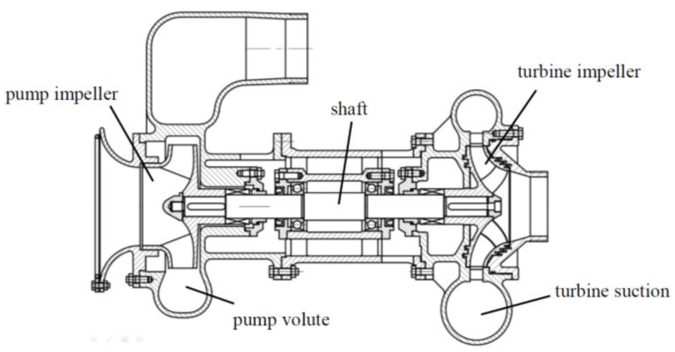
2.1. Fire Turbopump Specifications

The main focus of this research is to understand the vibration characteristics induced by radial hydraulic force on the fire turbopump at a nominal operating condition in Table 1. The fire turbopump considered in this study contains the turbine impeller with a 152 mm diameter and the pump impeller with a 156 mm diameter. The turbine impeller was designed to be a complex impeller with 15 main blades and 15 splitter blades for improving waterpower utilization rate of the turbine, while the pump impeller with 5 blades was adopted due to the fact that this impeller structure can meet the design requirements for the fire turbopump.

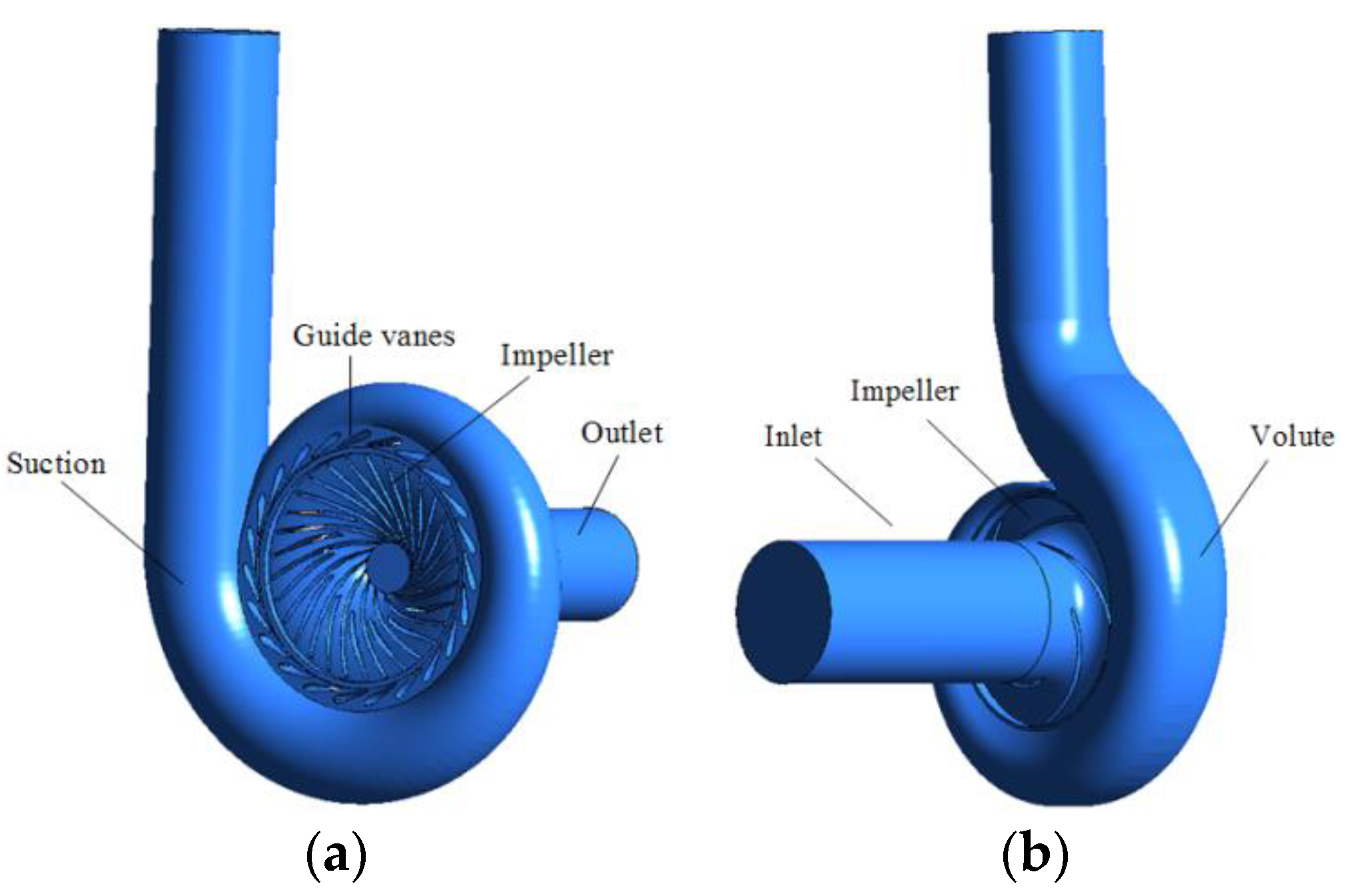
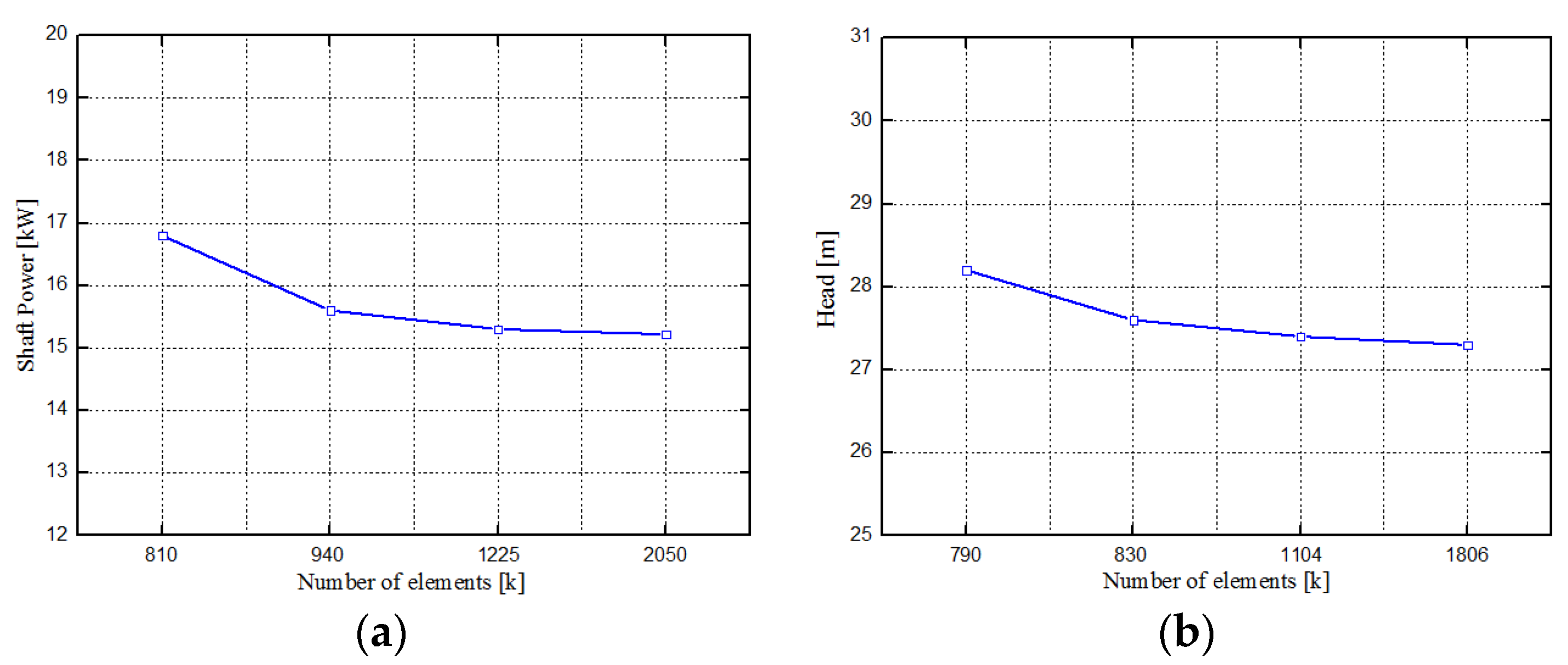
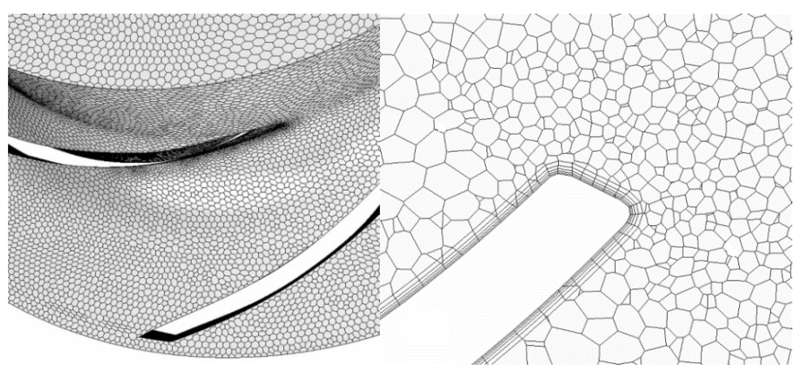
2.2. CFD Methodology

The numerical simulations for the fire turbopump were divided into simulations on the turbine section and pump section under the operating condition of the turbopump. The entire computational domain of fire turbopump is shown in Figure 2, including the turbine suction (containing guide-vane passage), turbine impeller passage, pump impeller passage, pump volute and the extension of inlet and outlet. The polyhedral mesh was generated for each independent domain as shown in Figure 3. The mesh density was also studied to verify the independence of the number of elements for the solution. Turbine shaft power and pump head were used as variables of reference to analyze the mesh independence. Figure 4 presents that the solution independent of the mesh with significant computational saving is provided by the mesh with 1.2 million grid points for turbine section and with 1.1 million grid points for pump section.
Three-dimensional steady and unsteady flow analyses were performed to study performance characteristics and radial hydraulic forces of the fire turbopump based on the OpenFOAM platform. The steady flow was numerically simulated by using the same computational domains, and the results were used as the initial conditions for the unsteady simulations. The Shear Stress Transport (SST) turbulence model was employed on account of the curved passage and the rotational flow [20]. Turbine impeller and pump impeller are rotational components, while the other parts are considered under stationary. The connection interface between turbine suction and turbine impeller was a Frozen Rotor interface. Similarly, the connection interface between pump impeller and pump volute was a Frozen Rotor interface. For the unsteady simulations, the grids are connected by means of a rotor/stator interface, i.e., they change their relative position through the simulation according to the angular velocity of the impeller. The reference change occurs as the flow crosses the interfaces; the appropriate transformation occurs across the interface without any interface averaging. The boundary conditions used in the numerical simulations are summarized in Table 2, and represents the operating conditions of the fire turbopump.
In the unsteady flow, the discretization in space was of second-order accuracy and the second-order backward Euler scheme was chosen for the discretization in time. The connection interface was set to “transient rotor–stator”. The convergence criteria for all variables were set as 10−5. Unsteady flow simulations with 1 degree, 2 degrees, 3 degrees and 4 degrees of runner rotation were conducted to analyze the effect of the time step on the turbopump performances. There is less difference among simulations with 1 degree, 2 degrees and 3 degrees in the respects of inner flow characteristics and performances of pump and turbine. Considering the simulation power and storage capacity of the computer, the time step was considered as 3 degrees of revolution and the duration time was the length of the runner rotating eight revolutions for the unsteady flow simulation.

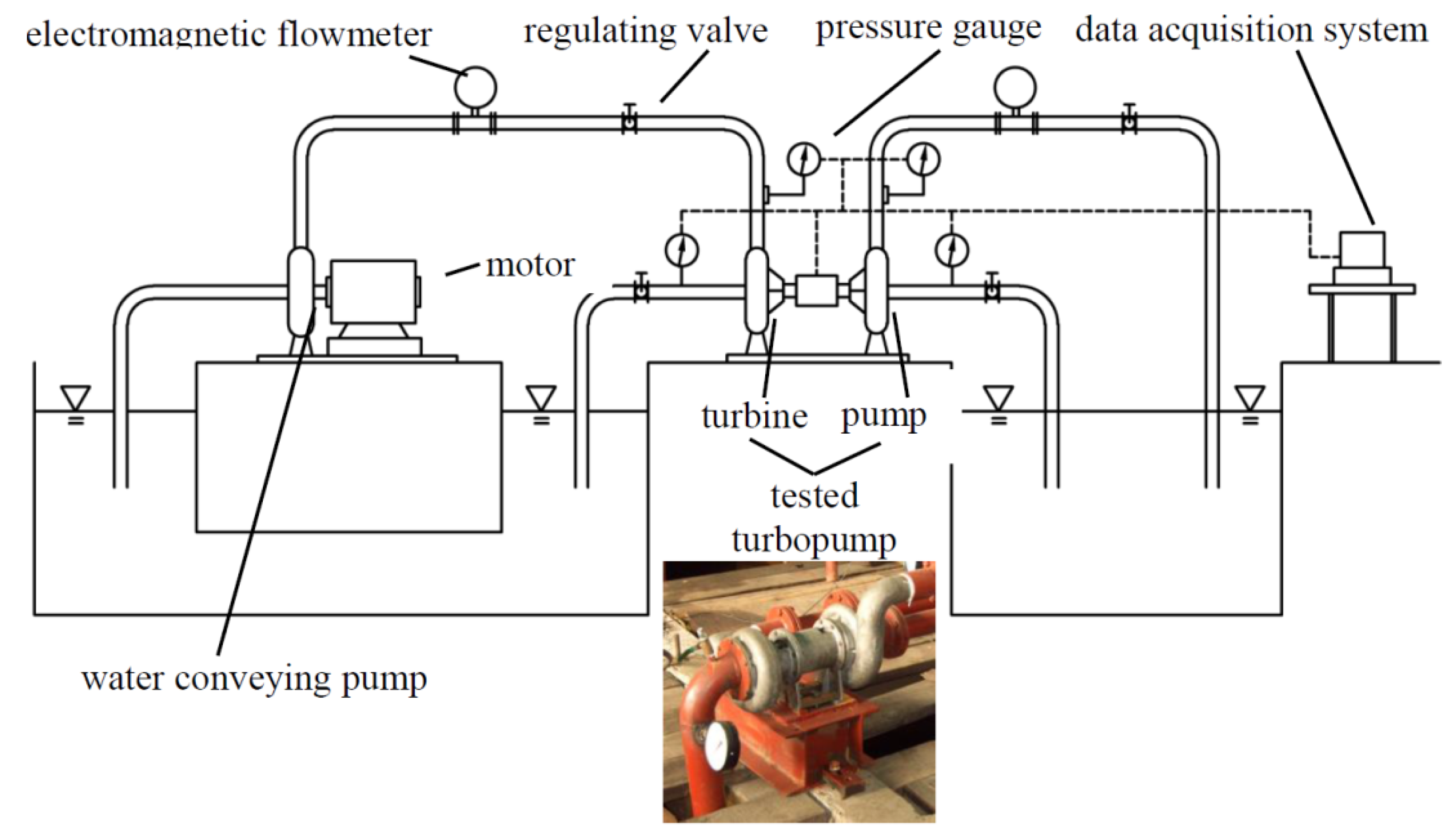
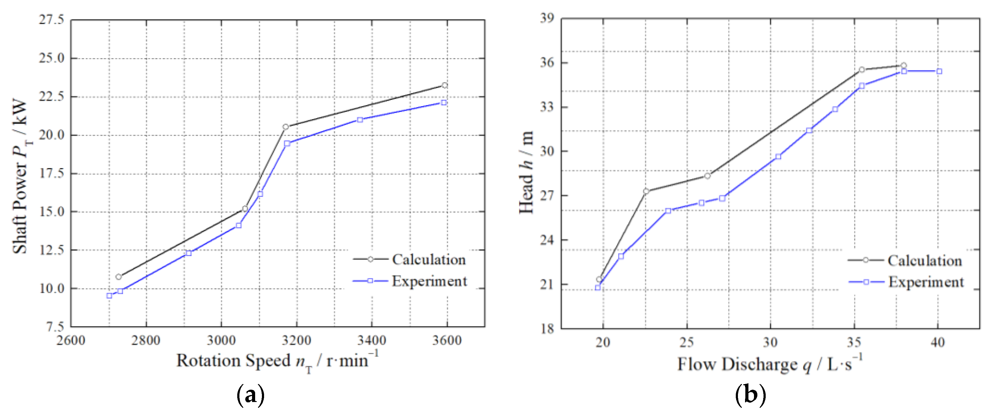
2.3. Experimental Measurements

The experiment was designed and conducted to validate the accuracy of the numerical methodology adopted in the paper for the fire turbopump. The testing apparatus was composed of a tested fire turbopump, a water conveying pump, two electromagnetic flowmeters, four pressure gauges, some regulating valves, pipeline and the data acquisition system, as shown in Figure 5. The water conveying pump provides water source to drive the tested fire turbopump and to adjust the shaft rotation speed of the turbopump by changing the water supply flow, and then the pump of the tested fire turbopump can draw water from experimental tank at different operating conditions. The experimental data was collected and processed by the data acquisition system for comparing with the numerical results to verify the CFD numerical model. Indeed, Figure 6 shows the global characteristic curve issued from the numerical calculation as well as the experimental characteristic curve. The experimental operating points of the turbopump are composed of uniform operating points and special operating points. The turbopump operating condition is determined by the coupling effects of turbine and pump, which induces the bending in the performance curves of turbine and pump. Meanwhile, this phenomenon causes some differences of error difference under different working conditions. However, from the turbine speed characteristic curve and the pump performance characteristic curve, the agreement between the CFD and the experimental results was observed. Moreover, the error measured between numerical and experimental results for the fire turbopump was investigated; the absolute errors at the nominal operating condition for the turbine and pump are 4.82% and 3.01%, respectively. The error is caused by model processing, assembly, experimental device error and experimental instrument accuracy, which is acceptable for this paper.

3. Results and Discussions

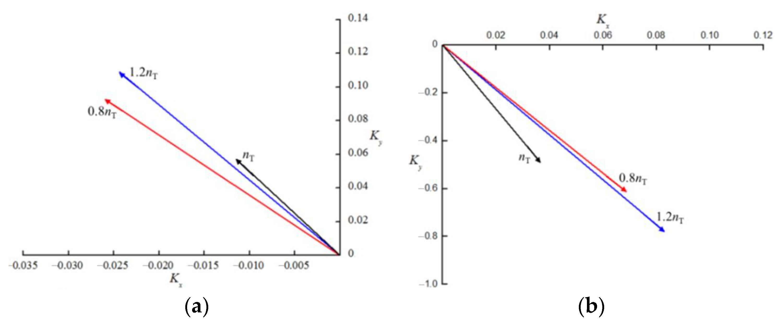
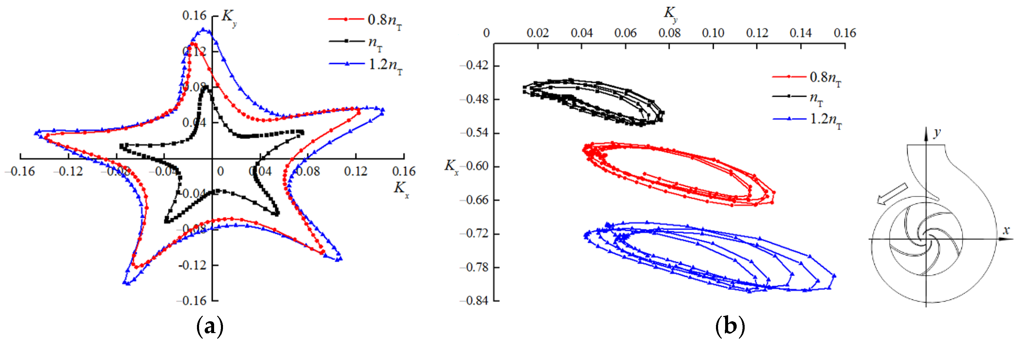
3.1. Radial Hydraulic Force on the Separate Turbine

The radial hydraulic force is generated on the turbine because of inner unsteady flow characteristics. The numerical simulations of flow characteristics were carried out at three different rotation speeds values (0.8nT, nT and 1.2nT). At the mid-planes of turbine section, normal to the rotating axis, pressure distributions are presented in Figure 7. High pressures exist in the suction, and there is the obvious pressure difference between the suction and impeller channel. The turbine suction plays the role of the rectifier and bears the majority of the water impact.
The static pressure distribution on the coupling surface between impeller and volute was obtained by numerical simulation. The force on each node of the decoupling surface was calculated when the static pressure is evenly distributed near each grid node of the coupling surface. Then, the forces on the x-axis and y-axis were calculated, respectively, by the quadrature method. Based on the decomposition and synthesis theorem of the force, the size and direction of the total force was obtained as shown in the Equations (1)–(6).
F i = P i ( 2 π R 2 B 2 N )
F i x = F i ( x i R 2 )
F i y = F i ( y i R 2 )
F x = i = 1 N F i x
F y = i = 1 N F i y
F = F x 2 + F y 2
where F is the radial hydraulic force (N), Pi is the pressure at the ith grid node, R2 is the impeller radius (m), b2 is the impeller inlet/outlet width in the decoupling surface (m), N is the coupling surface mesh node number, F i x is the component of pressure on the ith grid node in the x-axis direction, F i y is the component of pressure on the ith grid node in the y-axis direction, F x is the component of radial force in x-axis direction and F y is the component of radial force in y-axis direction. A radial hydraulic force coefficient K was defined the force variation, as follows:
K = F π ρ R 2 B 2 u 2
where u is the circumferential velocity in the largest base circle of the impeller (m/s).
Figure 8 shows the initial direction and magnitude of radial hydraulic force on the turbine section under three operation conditions. The value of the force on the normal impeller rotation is smaller than that on abnormal operation conditions. The direction of the force on the suction is in the second quadrant, while that on the impeller is in the first quadrant. Figure 9 presents the force variations in one full cycle of impeller rotation. The radial hydraulic force on the suction seems to vary randomly but has an elliptical trajectory like the force on the impeller. The suction is a rectifier to improve the unsteady flow characteristics of the inflow for increasing the water energy utilization efficiency of the impeller. These unsteady flows in the suction generate random variations of the force. Remarkably, the initial states and changing trends of the forces on the turbine are close for different conditions; the fire turbopump is typically used in normal conditions. Thus, the force characteristics on the normal impeller rotation were selected as research subjects for further study, as shown in Figure 10 and Figure 11.
Figure 10 presents the time-history results of radial hydraulic forces on the turbine section in one full working cycle. These forces on the suction and impeller experience a few increases, then decrease, and then increase. These changing processes are developing with some small fluctuations. If neglecting the effects of these small fluctuations, there are one crest and one trough in the force variation for one cycle of impeller rotation. For the suction, the K value of the crest is 1.651 at the time of 0.004 s and that of the trough is 1.649 at the time of 0.015 s, while for the impeller the K value of the crest is 0.032 at the time of 0.003 s and that of the trough is 0.026 at the time of 0.012 s. The K amplitude in the force variation for the suction is approximately 0.002, while that for the impeller is 0.006. The periodical force fluctuation is formed when the turbine is running. This behavior will affect the steady operation of pump section by the resonance.
The frequency domain analyses for the force fluctuations on the turbine section are contained to study resonance characteristics of the fire turbopump, as shown in Figure 11. The frequency domain results were transformed from the time domain results by the fast Fourier transform (FFT) method. For the fire turbopump, the shaft rotating speed keeps a constant value of 3000 r/min; thus, the shaft rotating frequency fR is 50 Hz. Some obvious fluctuations can be observed on the frequencies of 15fR and 30fR on the turbine section, and the fluctuation amplitude on the 15fR is bigger. The turbine impeller has 30 blades including 15 main blades and 15 splitter blades. The frequencies of 15fR and 30fR are named “impeller blade passing frequency”.

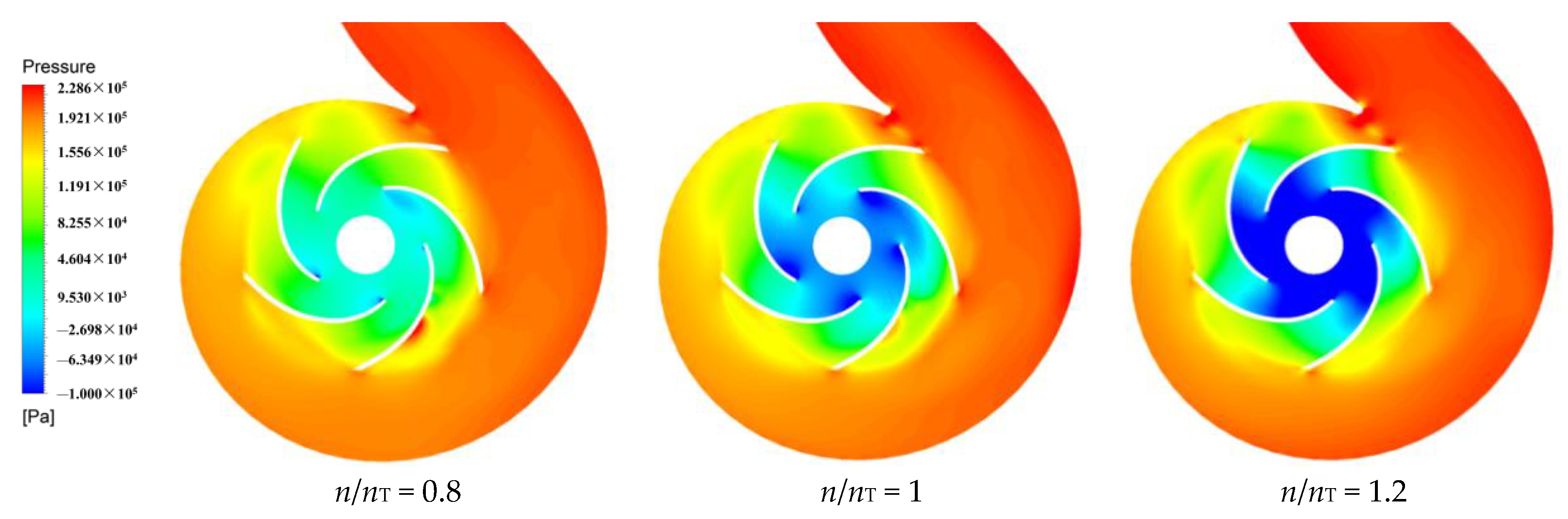
3.2. Radial Hydraulic Force on the Separate Pump

In this section, the characteristics of radial hydraulic force on the pump section operated independently are studied in this part. The pump delivers water in a certain way, and the flow is controlled by the pump structure and operation condition. The water flows in the pump without many impacts, not like in the turbine. Figure 12 presents pressure distributions on the radial mid-planes of the pump at three different rotation speed values (0.8nT, nT and 1.2nT). The water pressure gradually increases along the flow channel of pump. The pressure experiences a uniform variation in the pump, and is different from the abrupt change in the transition zone between turbine suction and turbine impeller. In the conditions of 0.8nT, flow separation structure is existed in the blade passage, which generates force excitation on the blade. Meanwhile, there is obvious pressure difference between blade pressure surface and blade suction surface in the 1.2nT condition; this phenomenon causes the larger force magnitude, as compared with 0.8nT and nT.
Figure 13 presents the initial direction and magnitude of radial hydraulic force on the pump section under three operation conditions. The value of the force on the normal impeller rotation is obviously smallest. There is little difference between the conditions of 0.8nT and 1.2nT for the force on the impeller. The direction of the force on the impeller is in the second quadrant, while that on the volute is in the fourth quadrant. Figure 14 shows the force variations in one full cycle of the impeller rotation. Radial force characteristics of five periodic variations are obviously exhibited for the impeller and volute, which is consistent with the blade number of impeller structure. The phenomenon illustrates that the flow excitation in the impeller passage is the main source of radial force on the pump section.
The time-domain analysis of the radial hydraulic force on the pump section in one full working cycle was conducted as shown in Figure 15. The obvious periodicity of force fluctuation can be observed, and the periods of fluctuations on the impeller and volute are close, but the fluctuation extents are different. The K amplitude on the impeller is 0.046, while that on the volute is approximately 0.09. Figure 16 displays the frequency domain results of radial hydraulic forces on the pump. There are obvious fluctuation amplitudes on the frequencies of 5fR, 10fR and 15fR. The frequency of 5fR has the bigger amplitude of the fluctuating force, which is affected by the impeller structure.

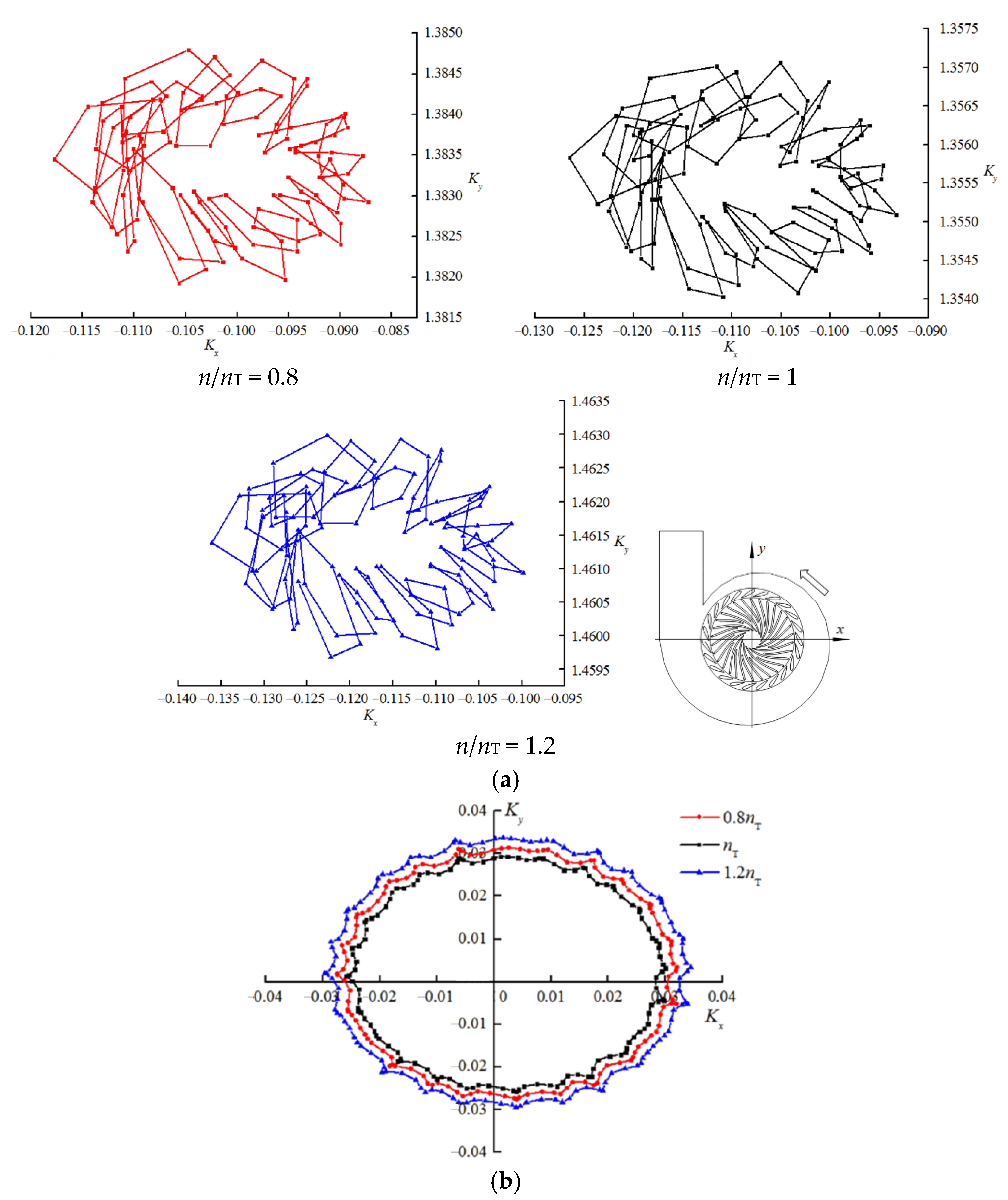
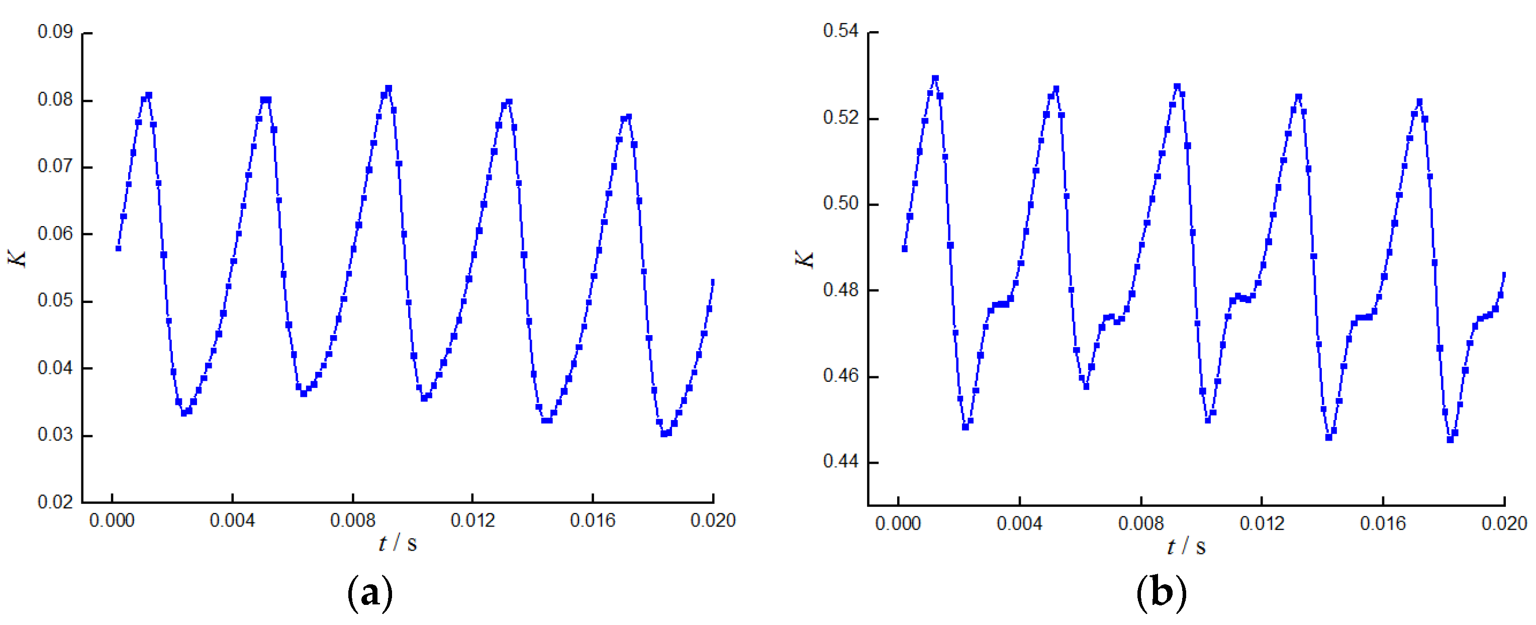
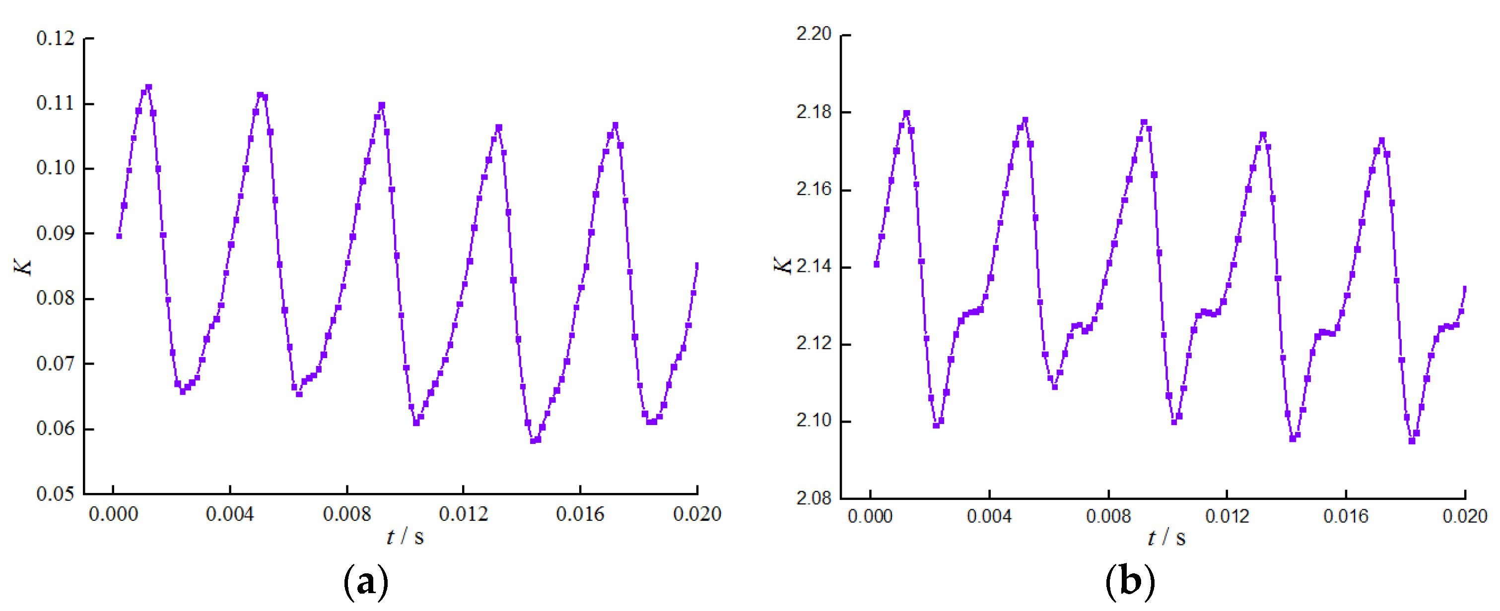
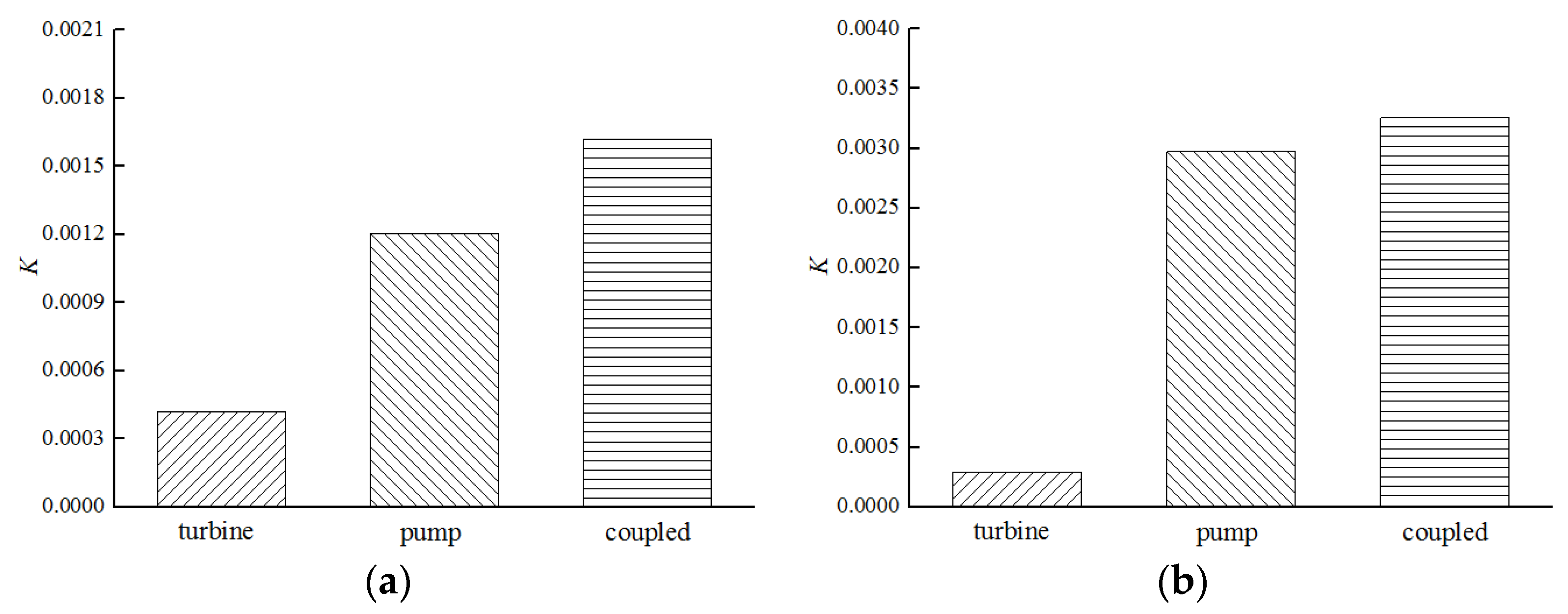
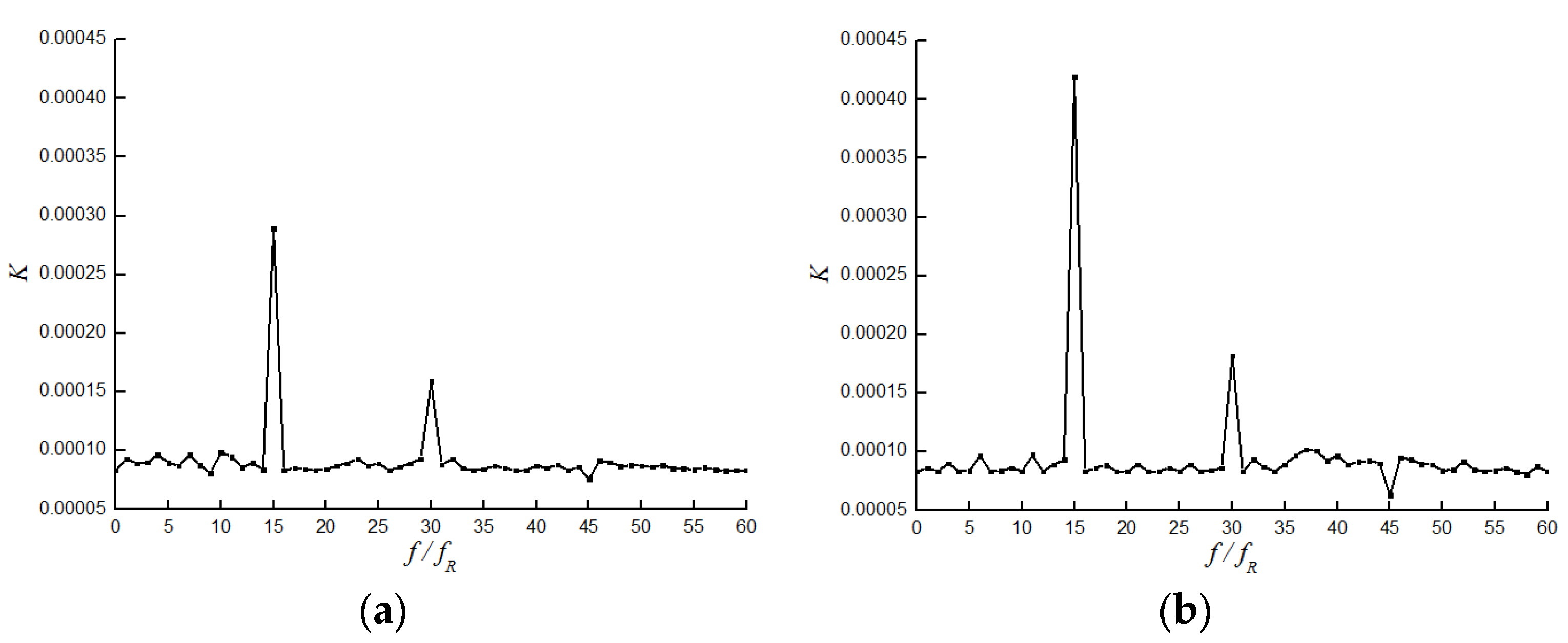
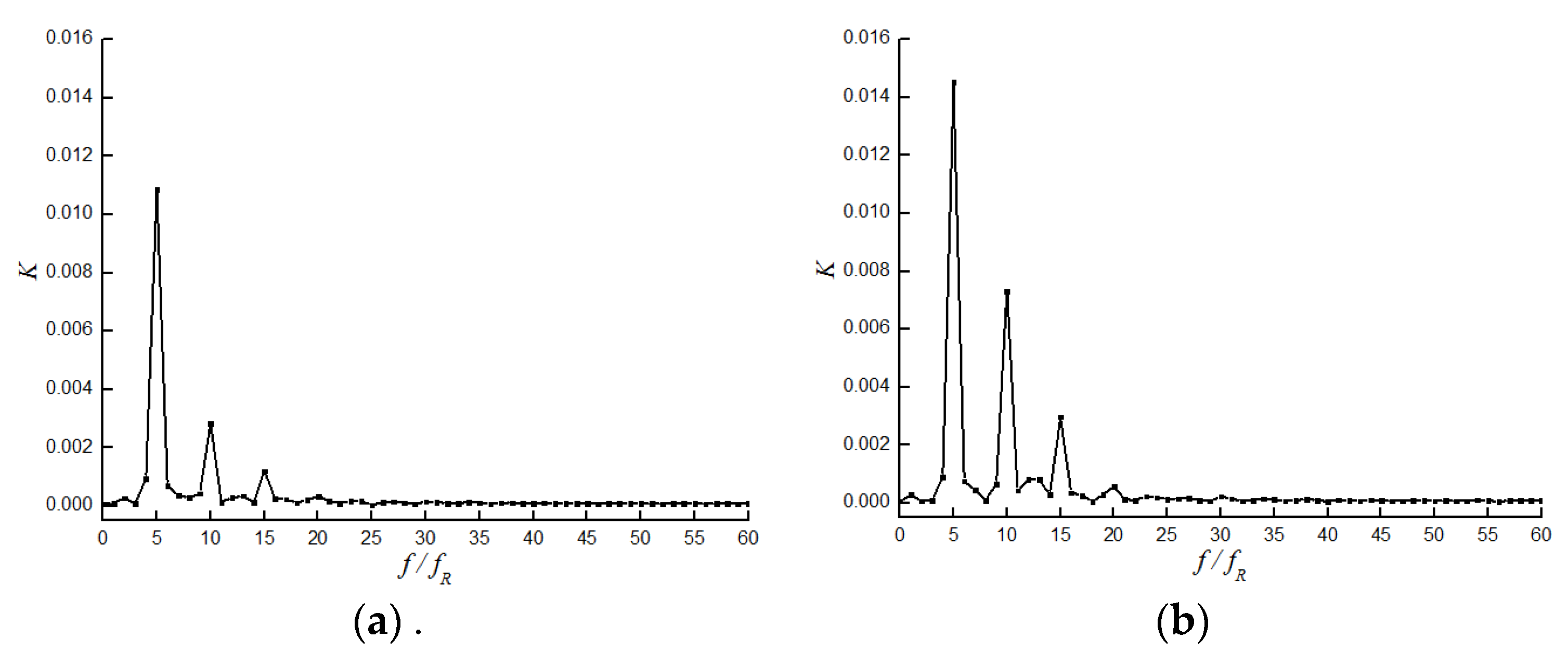
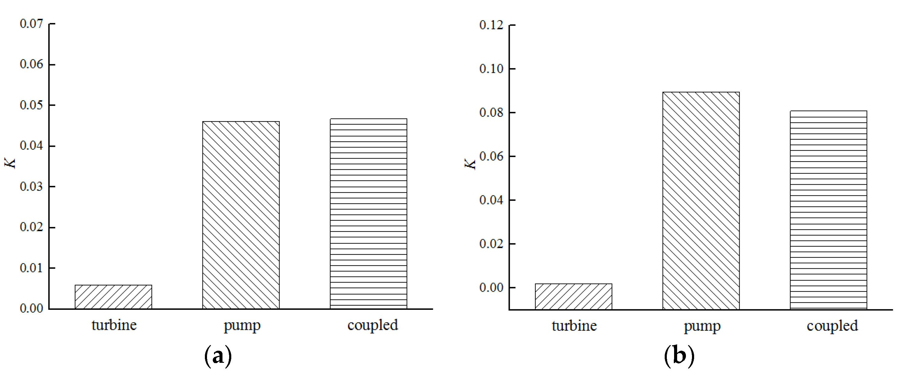
3.3. Coupled Characteristics of Radial Hydraulic Force on the Turbopump

The fire turbopump has the special structure with two hydraulic machineries of a turbine and a pump, and this structure results in the coupled effects on the operation characteristics between turbine section and pump section. The internal flow structures in both hydraulic machineries are affected by the interaction of the hydraulic force fluctuations between turbine impeller and pump impeller connected by the shaft. Likewise, this coupled effect of the force fluctuations between turbine suction and pump volute joined by the housing induces the serious vibration of the turbopump unit.
Figure 17 shows the time-history results of the coupled hydraulic forces on the turbopump in one full working cycle. The impeller and housing are acted upon by the periodical force fluctuations, similar to the separate pump. This illustrates that the periodicity of the force fluctuation on the turbopump is dominated by pump structure. The internal flow field in the turbine is also affected by the periodical fluctuations. Meanwhile, the turbopump housing presents the periodical vibration. Figure 18 shows the amplitudes of the force fluctuations on the separate turbine, the separate pump and the turbopump. For the impeller, the coupled amplitude is higher than the fluctuation amplitudes of turbine section and pump section. The coupled effect between turbine impeller and pump impeller is enhanced by the connection of the shaft. Nevertheless, the fluctuation amplitude of the turbopump housing is lower than that of the pump volute; this is because the coupled force fluctuation is dampened by counteracting the forces between turbine suction and pump volute. The direction of the force on the turbine suction is in the second, while that on the pump volute is in the fourth quadrant.
According to the fluctuation frequencies in Figure 11 and Figure 16, the force fluctuations on the turbine and pump at the frequency of 15fR result in the resonance. Figure 19 shows the fluctuation amplitudes on the separate turbine, the separate pump and the turbopump. The amplitude at the resonant frequency is higher than that on the separate turbine and pump. However, as for the whole frequency domain, the force fluctuation at the frequency of 15fR is not severe, as shown in Figure 20. The amplitude at the frequency of 5fR is highest, and close to the fluctuation amplitude on the separate pump. This illustrates that the force characteristics in the frequency domain are also determined by the pump.

4. Conclusions

In this paper, the fluctuation characteristics of radial hydraulic force on the fire turbopump were studied by numerical simulations. The accuracy of the CFD methodology was validated by comparing with experimental results including turbine speed characteristics and pump performance characteristics. The absolute errors between the CFD and experimental results at the nominal operating condition for turbine section and pump section are 4.82% and 3.01%, respectively.
The unsteady CFD simulations successfully predicted the characteristics of hydraulic forces on the separate turbine, the separate pump and the turbopump. For the separate turbine, there are one crest and one trough in the force variation for one cycle of impeller rotation, the periodical force fluctuation is formed when the impeller is rotating. Some obvious fluctuations can be observed on the frequencies of 15fR and 30fR, and the fluctuation amplitude on the 15fR is bigger. For the separate pump, obvious five periods in the force fluctuation were observed and determined by impeller structure. There are obvious fluctuation amplitudes on the frequencies of 5fR, 10fR and 15fR, and the fluctuation amplitude on the 5fR is bigger. For the turbopump, the coupled effect of force fluctuations on the turbine and pump was explored. The periodicity of force fluctuation in the time domain and force characteristics in the frequency domain are dominated by pump structure. The hydraulic force fluctuation on the impeller is enhanced, while that on the housing is dampened by counteracting the forces between turbine suction and pump volute. These are useful to optimize the turbopump structure to reduce the flow-induced vibration.

Author Contributions

Data curation, Y.Y. and L.T.; funding acquisition, Y.Y.; investigation, R.J.; methodology, L.T.; project administration, Y.Y.; writing—original draft, Y.Y. and L.T. All authors have read and agreed to the published version of the manuscript.

Funding

This research was funded by the Natural Science Foundation of Jiangsu Province of China for Young Scholars (Grant No. BK20210883).

Conflicts of Interest

The authors declare no conflict of interest.

References

  1. Weng, A.H. Research state of water turbine pump. Water Turbine Pump. 1994, 1, 1–7. [Google Scholar]
  2. Fujian RI, M. Turbopump; China Machine Press: Beijing, China, 1978. [Google Scholar]
  3. Liang, J.W.; Cai, L.Q. Overview for Water turbine pump industry. Water Turbine Pump. 2000, 2, 4–8. [Google Scholar]
  4. Wang, L.J.; Yuan, Y.; Xue, L. Research on design of high-efficiency fire turbopump supplying water from low-level water resources. Adv. Mater. Res. 2013, 694, 652–658. [Google Scholar] [CrossRef]
  5. Wang, L.J.; Yuan, Y.; Xue, L. Research on unsteady pressure fluctuation within the whole flow passage of a fire turbopump. Adv. Mater. Res. 2014, 945, 956–963. [Google Scholar] [CrossRef]
  6. Tan, L.W.; Yang, Y.F.; Shi, W.D.; Chen, C.; Xie, Z.S. Influence of blade wrap angle on the hydrodynamic radial force of single blade centrifugal pump. Appl. Sci. 2021, 11, 9052. [Google Scholar] [CrossRef]
  7. Huang, S.; Wu, Y.L. Analysis of flow field asymmetry and force on a centrifugal pump by 3-D numerical simulation. Fluid Mach. 2006, 34, 30–33. [Google Scholar]
  8. Hideo, O. Vibration and Oscillation of Hydraulic Machinery; Avebury Technical Gower House: Farnham, UK, 1991. [Google Scholar]
  9. Guelich, J.; Jud, W.; Hughes, S.F. Review of parameters influencing hydraulic forces on centrifugal impellers. Proc. IMechE Part A J. Power Energy. 1987, 201, 163–174. [Google Scholar] [CrossRef]
  10. Yuan, Y.; Yuan, S.Q.; Tang, L.D. Numerical investigation on the mechanism of double-volute balancing radial hydraulic force on the centrifugal pump. Processes. 2019, 7, 689. [Google Scholar] [CrossRef] [Green Version]
  11. Christian, L. The determination of dynamic radial forces in hydraulic machines. Voith Res. Constr. 1992, 28, 27–30. [Google Scholar]
  12. Miyabe, M.; Furukawa, A.; Maeda, H.; Umeki, I. Rotating stall behavior in a diffuser of mixed flow pump and its suppression. In Proceedings of the ASME Fluids Engineering Division Summer Conference (FEDSM ’08), Jacksonville, FL, USA, 10–14 August 2008; pp. 1147–1152. [Google Scholar]
  13. Gayo, J.L.; Gonzalez, J.; Fernandez-francos, J. The effect of the operating point on the pressure fluctuations at the blade passage frequency in the volute of a centrifugal pump. Trans. ASME J. Fluids Eng. 2002, 124, 784–790. [Google Scholar] [CrossRef]
  14. Guo, S.; Maruta, Y. Experimental investigations on pressure fluctuations and vibration of the impeller in a centrifugal pump with vaned diffusers. JSME Int. J. Ser. B. 2005, 48, 136–143. [Google Scholar] [CrossRef] [Green Version]
  15. Arndt, N.; Acosta, A.J.; Brennen, C.E.; Caughey, T.K. Experimental investigation of rotor–stator interaction in a centrifugal pump with several vaned diffusers. ASME J. Turbomach. 1990, 112, 98–108. [Google Scholar] [CrossRef]
  16. Zhang, L.; Li, H.; Xu, H.; Shi, W.D.; Yang, Y.; Wang, W.H.; Zhou, L. Experimental and numerical investigation of pressure fluctuation in a low-specific-speed centrifugal pump with a gap drainage impeller. Shock Vib. 2021, 2021, 5571178. [Google Scholar] [CrossRef]
  17. Yang, F.; Li, Z.B.; Yuan, Y.; Liu, C.; Zhang, Y.Q.; Jin, Y. Numerical and experimental investigation of internal flow characteristics and pressure fluctuation in inlet passage of axial flow pump under deflection flow conditions. Energies 2021, 14, 5245. [Google Scholar] [CrossRef]
  18. Gonzalez, J.; Fernandez, J.; Blanco, E.; Santolaria, C. Numerical simulation of the dynamic effects due to impeller-volute interaction in a centrifugal pump. Trans. ASME J. Fluid Eng. 2002, 124, 348–355. [Google Scholar] [CrossRef]
  19. Zhang, M.; Tsukamoto, H. Unsteady hydrodynamic forces due to rotor-stator interaction on a diffuser pump with identical number of vanes on the impeller and diffuser. ASME Fluids Eng. 2005, 127, 743–751. [Google Scholar] [CrossRef]
  20. Tang, L.D.; Yuan, S.Q.; Tang, Y.; Gao, Z.J. Performance characteristics in runner of an impulse water turbine with splitter blade. Processes. 2021, 9, 303. [Google Scholar] [CrossRef]
  21. Muggli, F.A.; Eisele, K.; Zhang, Z.; Casey, M.V. Numerical investigations of the flow in a pump turbine in pump mode. In Proceedings of the 3rd European Conference on Turbomachinery, London, UK, 2–5 March 1999; pp. 997–1002. [Google Scholar]
  22. Yuan, Y.; Yuan, S.Q.; Tang, L.D. Investigation on the effect of complex impeller on vibration characteristics for a high-speed centrifugal pump. Proc. Inst. Mech. Eng. Part A J. Power Energy. 2020, 234, 611–624. [Google Scholar] [CrossRef]
Figure 1. Fire turbopump structure.
Applsci 12 04650 g001
Figure 2. Computational domain. (a) Turbine section. (b) Pump section.
Applsci 12 04650 g002
Figure 3. Parts of computational grid.
Applsci 12 04650 g003
Figure 4. Mesh independence analysis. (a) Turbine section. (b) Pump section.
Applsci 12 04650 g004
Figure 5. Schematic diagram of experimental apparatus.
Applsci 12 04650 g005
Figure 6. Comparison between experiment result and numerical simulation. (a) Turbine speed characteristic curves. (b) Pump performance characteristic curves.
Applsci 12 04650 g006
Figure 7. Pressure distributions in the turbine.
Applsci 12 04650 g007
Figure 8. Initial direction and magnitude of radial hydraulic force: (a) On the volute; (b) On the impeller.
Applsci 12 04650 g008
Figure 9. Radial hydraulic forces in one full working cycle. (a) Volute. (b) Impeller.
Applsci 12 04650 g009
Figure 10. Time-domain results of radial hydraulic forces. (a) Turbine suction. (b) Turbine impeller.
Applsci 12 04650 g010
Figure 11. Frequency domain results of radial hydraulic forces. (a) Turbine suction. (b) Turbine impeller.
Applsci 12 04650 g011
Figure 12. Pressure distributions in the pump.
Applsci 12 04650 g012
Figure 13. Initial direction and magnitude of radial hydraulic force. (a) On the impeller; (b) On the volute.
Applsci 12 04650 g013
Figure 14. Radial hydraulic forces in one full working cycle. (a) Impeller. (b) Volute.
Applsci 12 04650 g014
Figure 15. Time-domain results of radial hydraulic forces. (a) Pump impeller. (b) Pump volute.
Applsci 12 04650 g015
Figure 16. Frequency domain results of radial hydraulic forces. (a) Pump impeller. (b) Pump volute.
Applsci 12 04650 g016
Figure 17. Time-domain results of the coupled hydraulic forces. (a) Impeller. (b) Housing.
Applsci 12 04650 g017
Figure 18. Amplitude of radial hydraulic force fluctuations. (a) Impeller. (b) Housing.
Applsci 12 04650 g018
Figure 19. Force amplitude at the frequency of 15fR. (a) Impeller. (b) Housing.
Applsci 12 04650 g019
Figure 20. Frequency domain results of the coupled hydraulic forces. (a) Impeller. (b) Housing.
Applsci 12 04650 g020
Table 1. Working condition of the fire turbopump.
Turbine Head
P/MPa
Turbine
Flow Discharge
Q/L·s−1
Pump
Flow Discharge
q/L·s−1
Pump Head
h/m
Rotate Speed
n/r·min−1
0.73537263000
Table 2. Boundary conditions used in the numerical simulation [21,22].
LocationBoundary ConditionOption
TurbineSuctionInletMass flow rate
Outlet extensionOutletOutflow
Solid surfacesWallNo slip wall
PumpInlet extensionInletVelocity
VoluteOutletMass flow rate
Solid surfacesWallNo slip wall
Publisher’s Note: MDPI stays neutral with regard to jurisdictional claims in published maps and institutional affiliations.

