Article

Microfabrication Bonding Process Optimization for a 3D Multi-Layer PDMS Suspended Microfluidics

by
Mostapha Marzban
1,2,
Ehsan Yazdanpanah Moghadam
1,
Javad Dargahi
2 and
Muthukumaran Packirisamy
1,*
1
Optical Bio-Microsystems Lab, Micro Nano Bio Integration Center, Department of Mechanical and Industrial Engineering, Concordia University, Montreal, QC H3G 1M8, Canada
2
Robotic Assisted Minimally Invasive Surgery Lab, Department of Mechanical and Industrial Engineering, Concordia University, Montreal, QC H3G 1M8, Canada
*
Author to whom correspondence should be addressed.
Appl. Sci. 2022, 12(9), 4626; https://doi.org/10.3390/app12094626
Submission received: 31 March 2022 / Revised: 20 April 2022 / Accepted: 27 April 2022 / Published: 4 May 2022
(This article belongs to the Special Issue Microfluidics in Biomedical Engineering)

Abstract

:
Microfluidic systems have received increased attention due to their wide variety of applications, from chemical sensing to biological detection to medical analysis. Microfluidics used to be fabricated by using etching techniques that required cleanroom and aggressive chemicals. However, another microfluidic fabrication technique, namely, soft lithography, is less expensive and safer compared to former techniques. Polydimethylsiloxane (PDMS) has been widely employed as a fabrication material in microfluidics by using soft lithography as it is transparent, soft, bio-compatible, and inexpensive. In this study, a 3D multi-layer PDMS suspended microfluidics fabrication process using soft lithography is presented, along with its manufacturing issues that may deteriorate or compromise the microsystem’s test results. The main issues considered here are bonding strength and trapped air-bubbles, specifically in multi-layer PDMS microfluidics. In this paper, these two issues have been considered and resolved by optimizing curing temperature and air-vent channel integration to a microfluidic platform. Finally, the suspended microfluidic system has been tested in various experiments to prove its sensitivity to different fluids and flow rates.

1. Introduction

Microfluidics has a wide variety of applications, from fluid pumping to flow properties measurement to biological sensing and detection [1,2]. In order to fabricate a microfluidic system, there are two main steps, namely microchannel fabrication and bonding.
There are different techniques for microchannel fabrication, namely etching in a glass or silicon and soft lithography for polymer-based substrates. Similarly, microchannel substrates are bonded with different methods such as fusion bonding, anodic bonding, solder bonding, thermo compression bonding for glass and silicon, adhesive bonding, and oxygen plasma bonding for polymer-based microchannel substrates.
Microfluidic channels were fabricated by etching in silicon and glass materials in standard microfabrication techniques [3,4]. Then, this was followed by bonding techniques with high bonding temperature, such as fusion bonding [5] and solder bonding [6], which require heat and pressure between substrates, and anodic bonding [7], which requires high voltage and temperature. However, the etching technique is expensive and uses hazardous chemicals.
Thus, microchannels made of polymeric materials using soft lithography techniques replaced former methods [8,9,10]. This technique does not require aggressive chemicals during fabrication and high temperature or pressure or excessive cleaning during bonding, which makes it less expensive compared to the previous methods. There are two main bonding techniques for polymer-based microchannels, namely adhesive [11] and plasma bonding [12].
Due to several advantages of PDMS, such as biocompatibility, optical transparency, and excellent mechanical properties, PDMS has been widely utilized for microfluidic devices [13,14]. Fabricating multi-layer microfluidic systems made with PDMS is still a challenge. Three-dimensional printing techniques as alternative approaches were proposed for one-step 3D fabrications with PDMS [15,16,17,18,19]. However, this method requires a substrate for printing microfluidic systems; thus, the fabrication process has to be optimized for printing PDMS-suspended microfluidics, such as microcantilevers.
Moreover, there was a problem in soft lithography, specifically when electronic elements are required to be embedded in microchannels. In order to fabricate this kind of microfluidics, a thin layer of the polymer such as PDMS has been used as an adhesive [20], which needs an exact control of the PDMS layer’s thickness for device performance or the channel may be blocked or deformed. Using uncured or partially cured PDMS as an adhesive has almost doubled the bonding strength compared to bonding strengths with the plasma technique [21].
Another issue with multiple layer microfluidics is trapped air bubbles between substrates during bonding. However, since PDMS is a gas-permeable polymer, air bubbles can escape if at least one substrate is not of a hard material such as glass. The trapped air bubbles can degrade the bonding strength, which causes leakage and dysfunction during microfluidic testing. In order to avoid trapped air bubbles, placing a grid of empty channels to suck the air bubbles out of microfluidics to free air was suggested by [20]. The grid of air channels is fabricated during the molding step, while microchannel mold is fabricated by using soft lithography.
In this study, we have proposed and tested an optimum number of air-vent channels between PDMS layers to remove trapped air bubbles. This allows using inexpensive plasma bonding method, which provides the required bonding strength for our experiments. Moreover, the PDMS curing temperature has been optimized to possess some stickiness during the bonding step. Since the thickness of the thin layer is around 200 µm in our fabrication procedure, using uncured or semi-cured PDMS may damage our thin substrates.

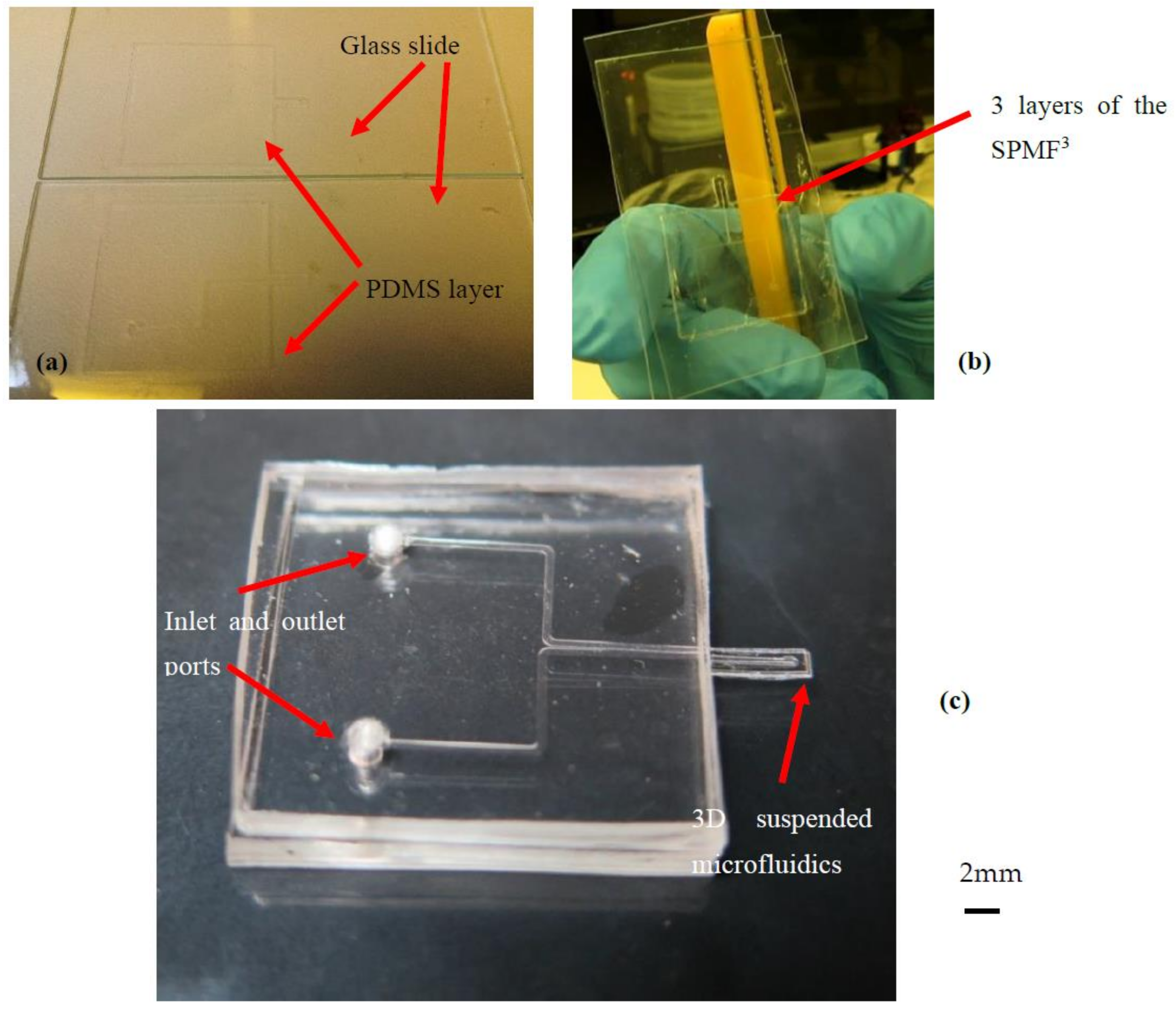
2. 3D Suspended Polymeric Microfluidic Resonator Fabrication (SPMF3)

A 3D suspended polymeric microfluidic resonator (SPMF3) [22,23] comprises three different layers, as shown in Figure 1. Two layers have microchannels, and the other one has a nozzle through which these two layers with microchannels are connected. Flow direction changes when it passes through the suspended microfluidics and applies flow forces onto the microcantilever. Monitoring the applied flow forces against flow properties can be used to measure different fluids properties using SPMF3 [22]. The detection and study of microparticles are among other applications of the SPMF3 platform that have been examined and published by current authors [24].
In order to obtain and optimize the suspended microfluidics’ dimensions, a finite element simulation with rough dimensions has been performed as the first iteration [25]. Then, an optimization analysis for sensitivity improvement is performed to obtain the optimum dimensions. Finally, the microsystem dimensions that have the highest sensitivity and deflection are chosen for sample fabrication: a microcantilever with the size of 6000 × 2000 × 600 µm3 with an embedded microchannel of 200 × 100 µm2. Detailed finite element analysis and sensitivity studies of the suspended microfluidics have been performed and published by the current author [25,26]. Table 1 summarizes the SPMF3 dimensions that have been used for simulations and the resulting deflection.

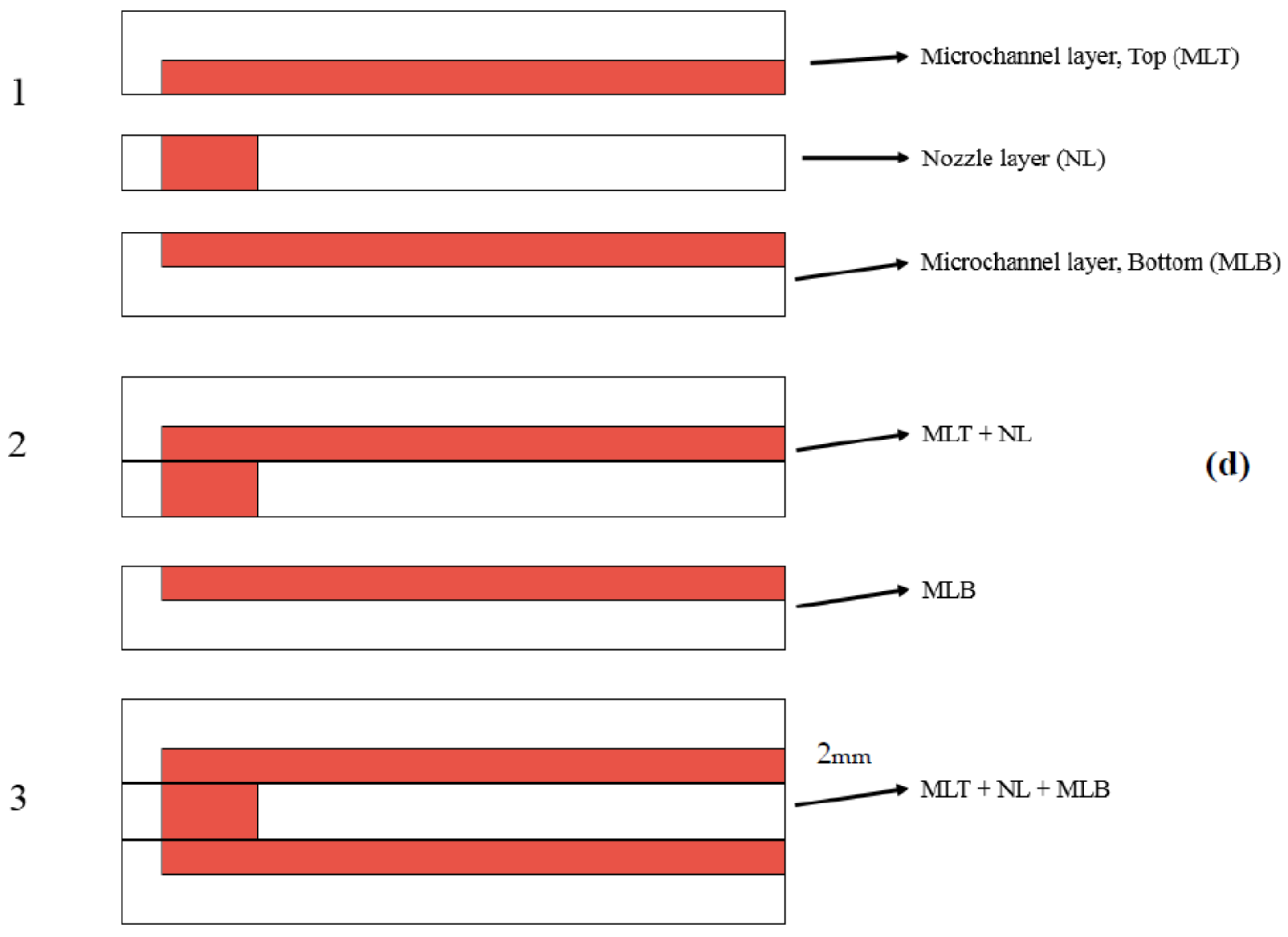
2.1. Fabrication Method

Soft lithography [27] is one of the main techniques for fabricating a PDMS microfluidic chip that starts with microchannel mold fabrication on a clean silicon wafer. The silicon wafer is coated with a photoresist material, SU8-2075, up to the desired microchannel depth by a spin-coating machine. After a pre-exposure baking step at 95 °C for 10–15 min, the silicon wafer is patterned using a mask with ultra-violet light (UV). Then, post-exposure baking is required to cure the patterned microchannel. Finally, the patterned photoresist material on the silicon wafer is submerged in a developer solution, which removes the unpatterned regions on the silicon wafer. Then, the mold is employed to fabricate the microchannel using a polymeric material such as PDMS. After having the microchannel substrate cured in an oven, the microchannel is bonded to a glass slide to form the microfluidic system and closed microchannels, as shown in Figure 2.

2.2. Fabrication Steps

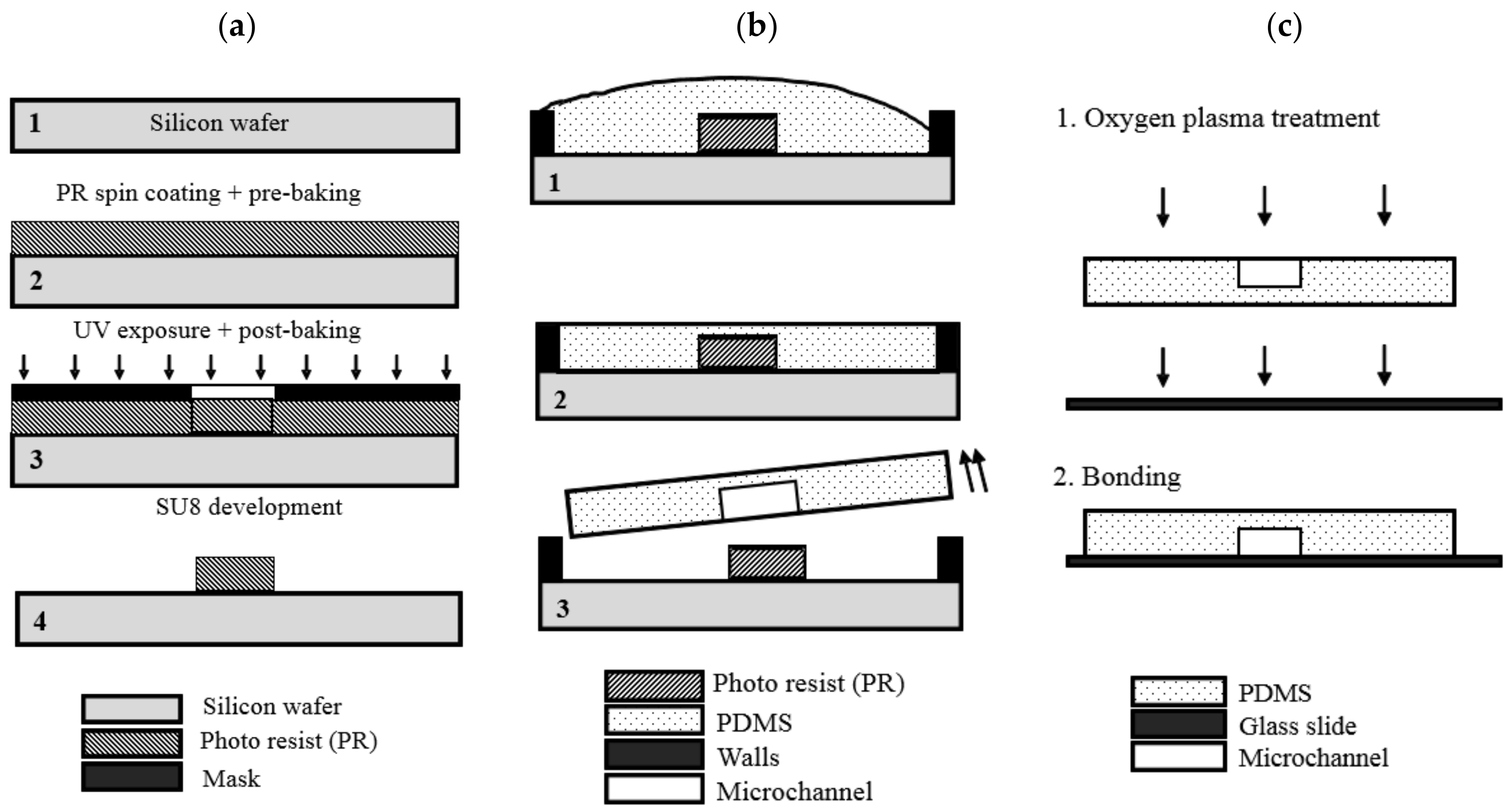
2.2.1. Mold Fabrication

In order to make each of the abovementioned layers, a proper mask and mold should be designed and fabricated. Three different masks are designed and fabricated, as shown in Figure 3; in this study, SU8-2075 has been used to make a mold for microsystem fabrication. This fabrication requires two different molds: one for microchannel layers and one for nozzle layers.
Lastly, the silicon wafer, including patterned and cured SU8, will be developed in a photoresistant developer solution to remove unpatterned areas from the mold, as shown in Figure 4. At the end, it is better to hard bake the mold at high temperatures to produce mold features that are hard and resistant.

2.2.2. PDMS Layers Fabrication Procedure

PDMS with a 10:1 ratio to curing agent is used in this fabrication process. After preparing liquid PDMS, it may be poured on the mold prepared earlier, as shown in Figure 4. By applying enough pressure on the mold, one makes sure that the final PDMS layer will be exactly made as designed. Applying pressure will be performed by using microscope glass slips, which are shown in Figure 5a. Finally, the mold should be heated at 65 °C for 2 h for curing. A gripper was also used to keep some pressure on the mold during curing to maintain the desired layer thickness.
The PDMS layer is ready to be bonded when it is detached from the mold after curing process, as shown in Figure 5d.

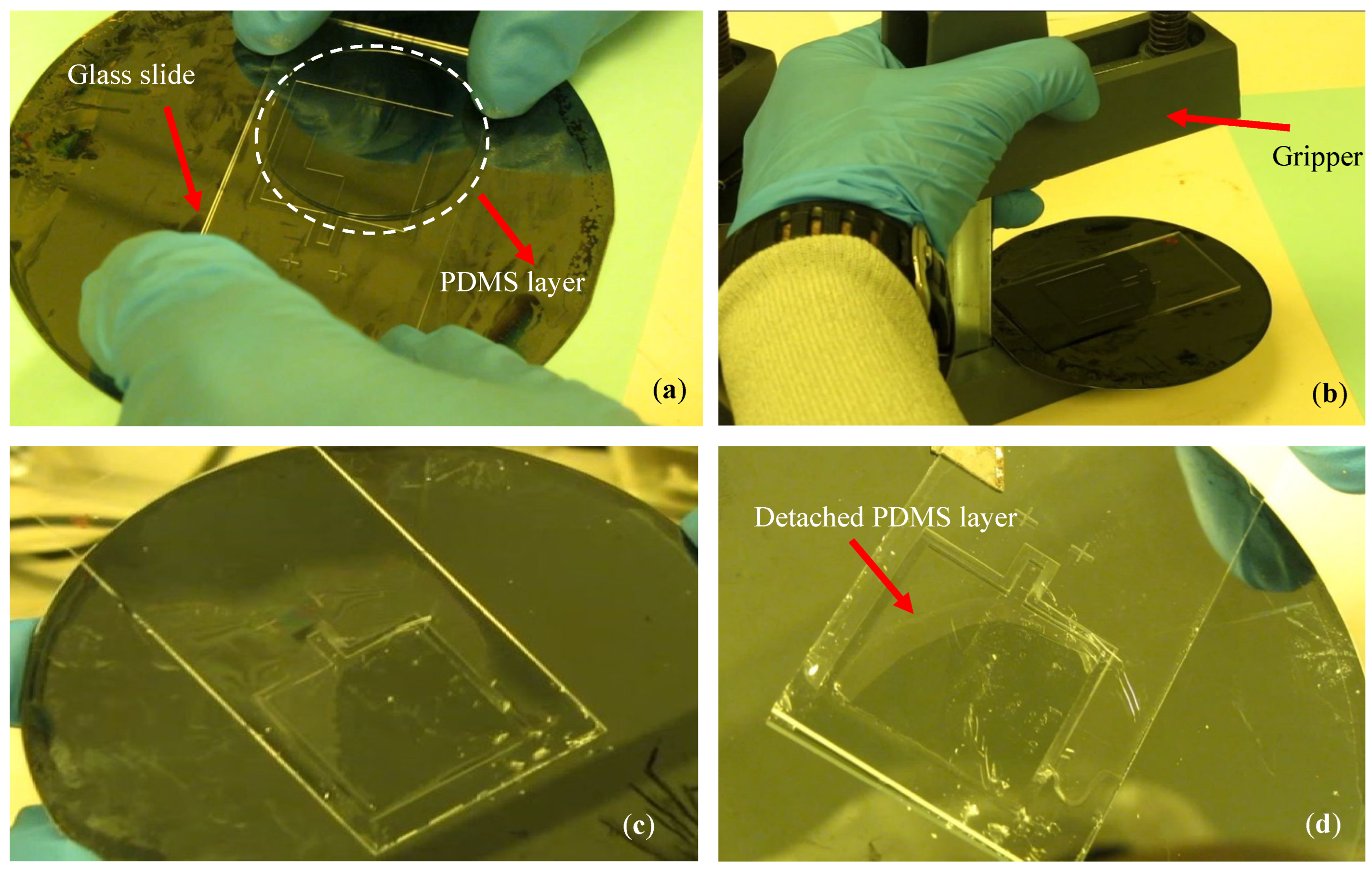
2.2.3. Bonding Procedure

In this step, each layer will be exposed to a 40 s plasma treatment and bonded carefully under the microscope for proper alignment using cantilever features. As observed in Figure 6, these two PDMS layers are placed on the glass slips used during the fabrication process. Thus, when bonding is completed, one of these glass slips (the nozzle one) has to be removed. This glass slip removal process has to be performed carefully. Otherwise, the entire delicate microstructure might become damaged. Now, two layers are bonded to each other (MLT + NL), and the third layer, which is the second microchannel layer (MLB), has to be bonded to these two layers. This will be performed in the same manner as the earlier bonding process for the first microchannel later to the nozzle layer. At the end, both glass slips at two sides of the 3-layer microfluidics will be removed, and proper supporting layers are bonded to hold the microsystem. Finally, the microcantilever in which a 3D microchannel is embedded is ready for fluid detection experiments and microparticle injection tests.

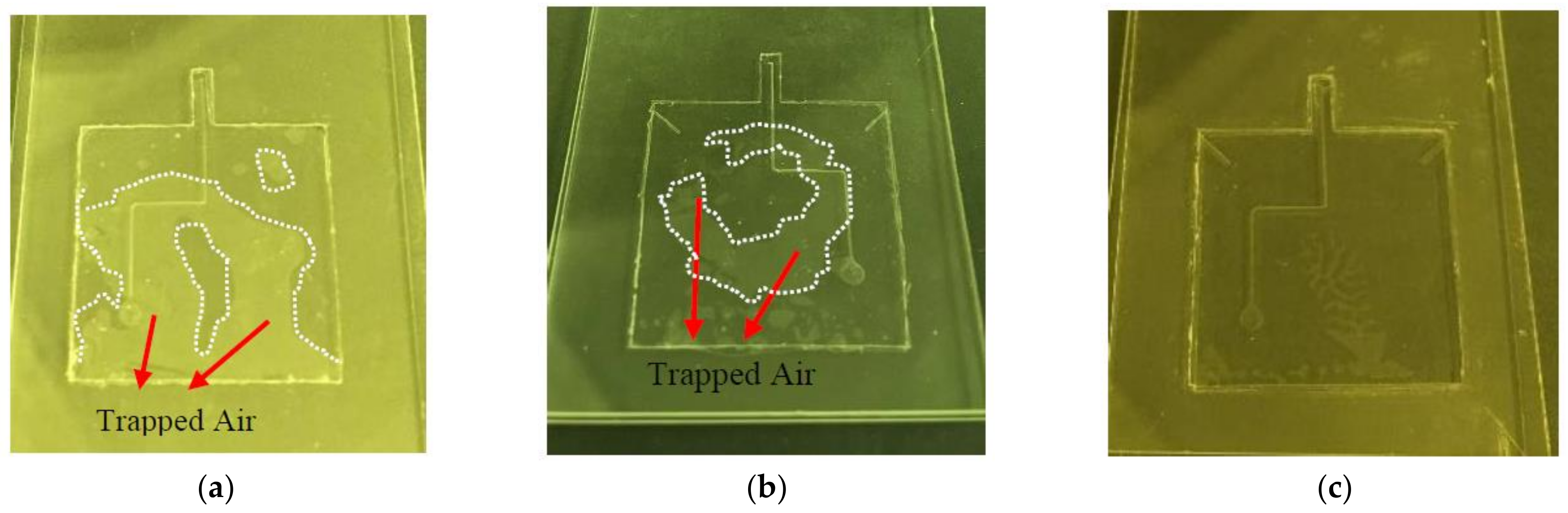
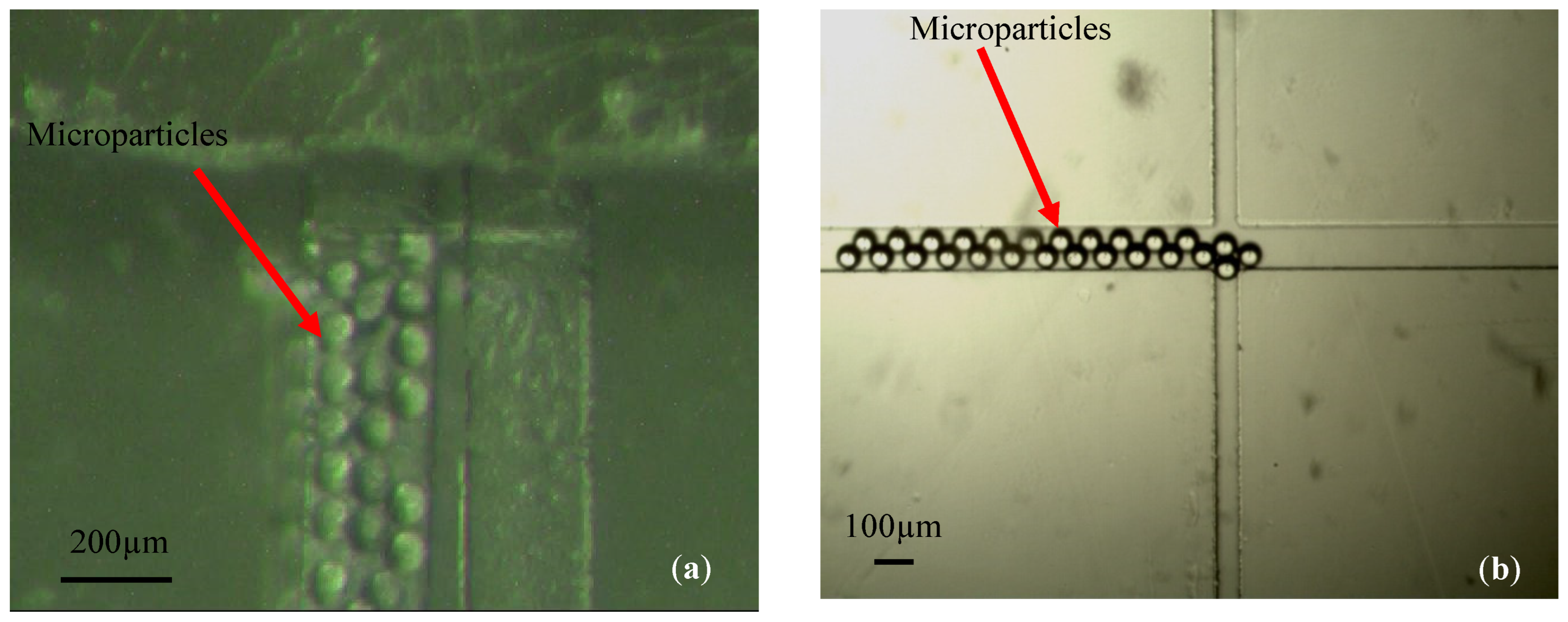
2.3. Fabrication Issues

During the fabrication process and after performing experiments with the suspended microfluidic system, some issues occurred that were related to the fabrication process. These issues and their solutions are listed as follows. Trapped air bubble between layers, bonding strength, and particles stickiness were fundamental points that needed attention to make microfluidics functional. There were some other issues that were minor but needed to be addressed, such as nozzle alignment and the quality of the nozzle hole.

2.3.1. Air-Vent PDMS Fabrication Method

As mentioned during the fabrication process, microchannel (MLU, MLB) and nozzle layers (NL) are placed on a glass slide during bonding, as shown in Figure 6a. Therefore, air bubbles may be trapped between layers during the bonding step, resulting in microfluidics dysfunction. In order to avoid this issue, two air-vent channels were designed and fabricated during the molding step, as shown in Figure 7. These channels help vent the trapped air bubbles out and consequently increases the bonding strength.
In order to optimize the air-vent channel’s dimensions, three suspended microfluidic systems with and without air-vent channels were fabricated and bonded. In this experiment, air-vent channels of 300 µm and 500 µm were integrated into the microchannel layer. As shown in the results, the air bubble is highly trapped in the fabrication without air-vent channels, which causes complete fabrication failure and unusable microfluidics, as shown in Figure 8.
However, when an air-vent channel of 300 µm was fabricated within the microchannel layer, the trapped air bubble transformed into multiple smaller bubble where there were no bubbles near the air-vent channels, which means that trapped air near these channels was taken out. Increasing the air-vent channel size to 500 µm removed most of the air bubbles and cleared all critical regions around the microchannel where the bonding strength was required. There is still a tiny portion of the trapped air left that is not in a critical region and can be removed with an extra air-vent channel in that zone.

2.3.2. Particle Stickiness

One of the main experiments performed in this research study was the detection and study of microparticles flow inside SPMF3 [24]. One of the main issues in dealing with microparticles in a PDMS microfluidics is the particles stickiness inside the channel (Figure 9). This is due to the presence of active ions on the microchannel walls [28]. In order to avoid this issue, which will block the microchannel, three solutions exist in the literature: diluting microparticle solution with anti-ion liquids such as TWEEN20 [29], covering microchannel walls with lubricants such as Teflon AF [30], and reducing the microparticle concentration in the solution [31].
Here, we tried a combination of diluting the microparticle solution with TWEEN20 and reducing their concentration in the solution, which worked perfectly during the experiments.

2.3.3. Bonding Strength

After fabricating several SPMF3 samples and conducting a simple flow test, it was observed that fluid leaks out of the microchannel and moves between microsystem layers. This is considered as a failure due to the low bonding strengths with respect to the desired tested flow rates. Therefore, one of the main parameters or issues that has to be monitored during the multi-layer fabrication process is bonding strength. The experimental results are unreliable if the layers are not bonded properly and fluid leaks between layers. In order to avoid this issue and based on best practices in the literature [21], the PDMS curing temperature was lowered from 90 °C to 65 °C in order to produce more sticky surfaces after curing. Moreover, the air-vent microchannels will also improve bonding strength by removing trapped air, which is required during fluid experiments with high flow rates.

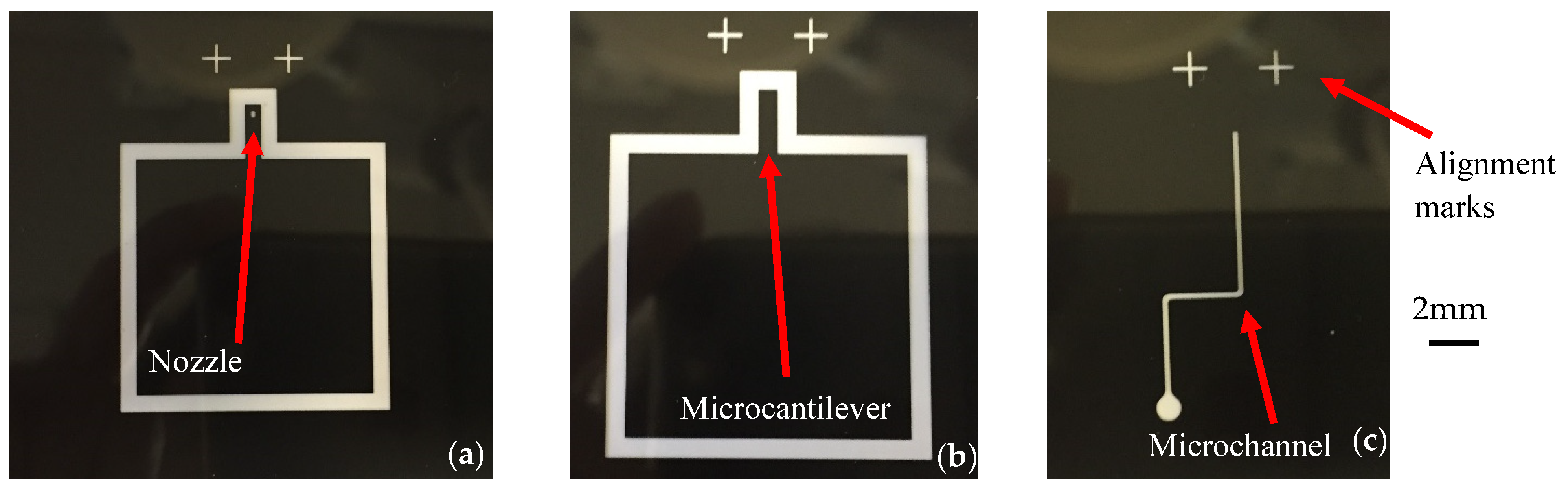
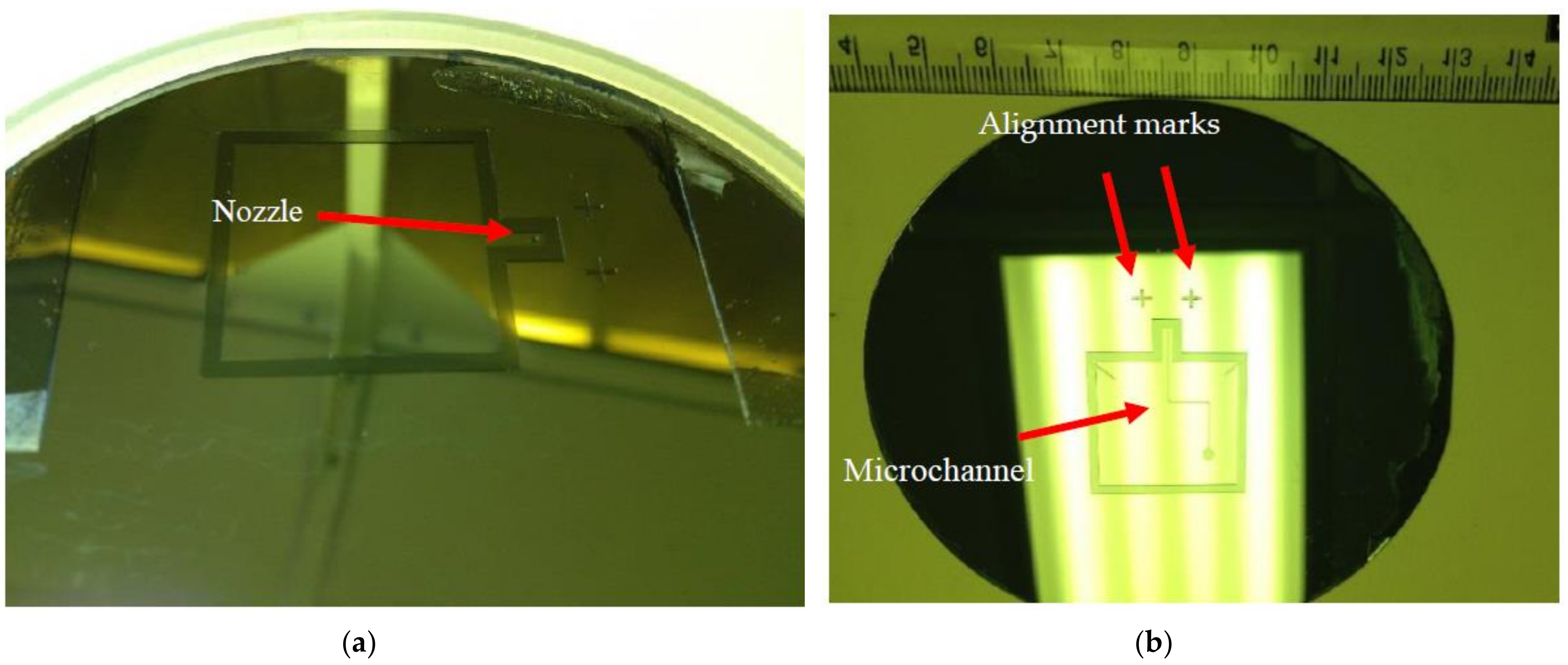
2.3.4. Alignment between PDMS Layers

The 3D-suspended microfluidics comprised five PDMS layers in which there are three main layers, namely one nozzle layer and two microchannel layers, and two supporting or sandwich layers on the top and bottom. The misalignment of the three main layers results in different designs and load sensitivity in the final suspended microfluidics. However, there are some situations in which bonding happens while the desired alignment is not reached. Since layer alignment was performed by hand and under a microscope, it is inevitable that sometimes the required alignment does not happen as it was planned, which is shown in Figure 10. Further attention under the microscope during the bonding process would resolve unwanted misalignments. Moreover, each SPMF3 should be tested after production for its baseline load sensitivity in order to remove variation error between different SPMF3 samples.

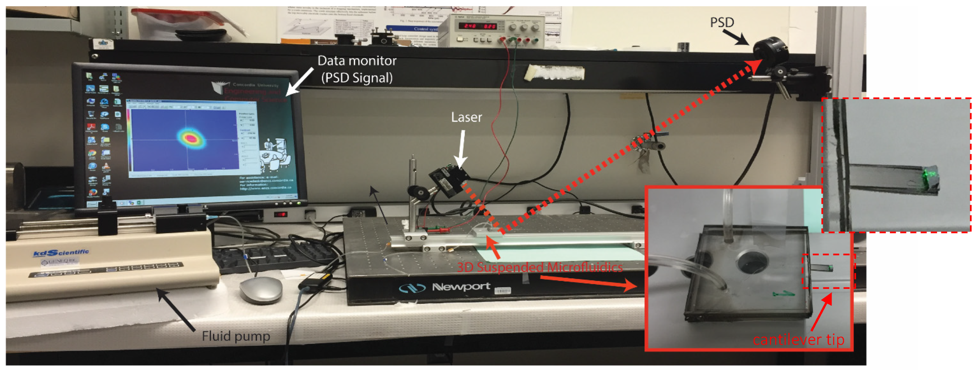
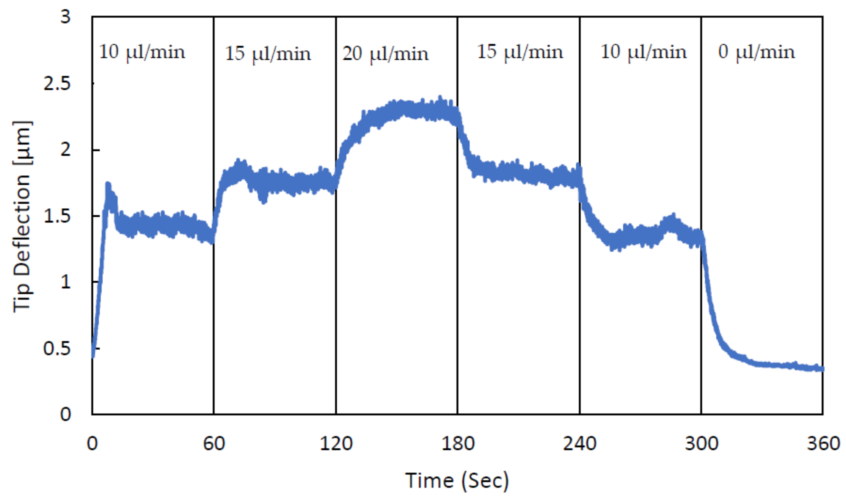
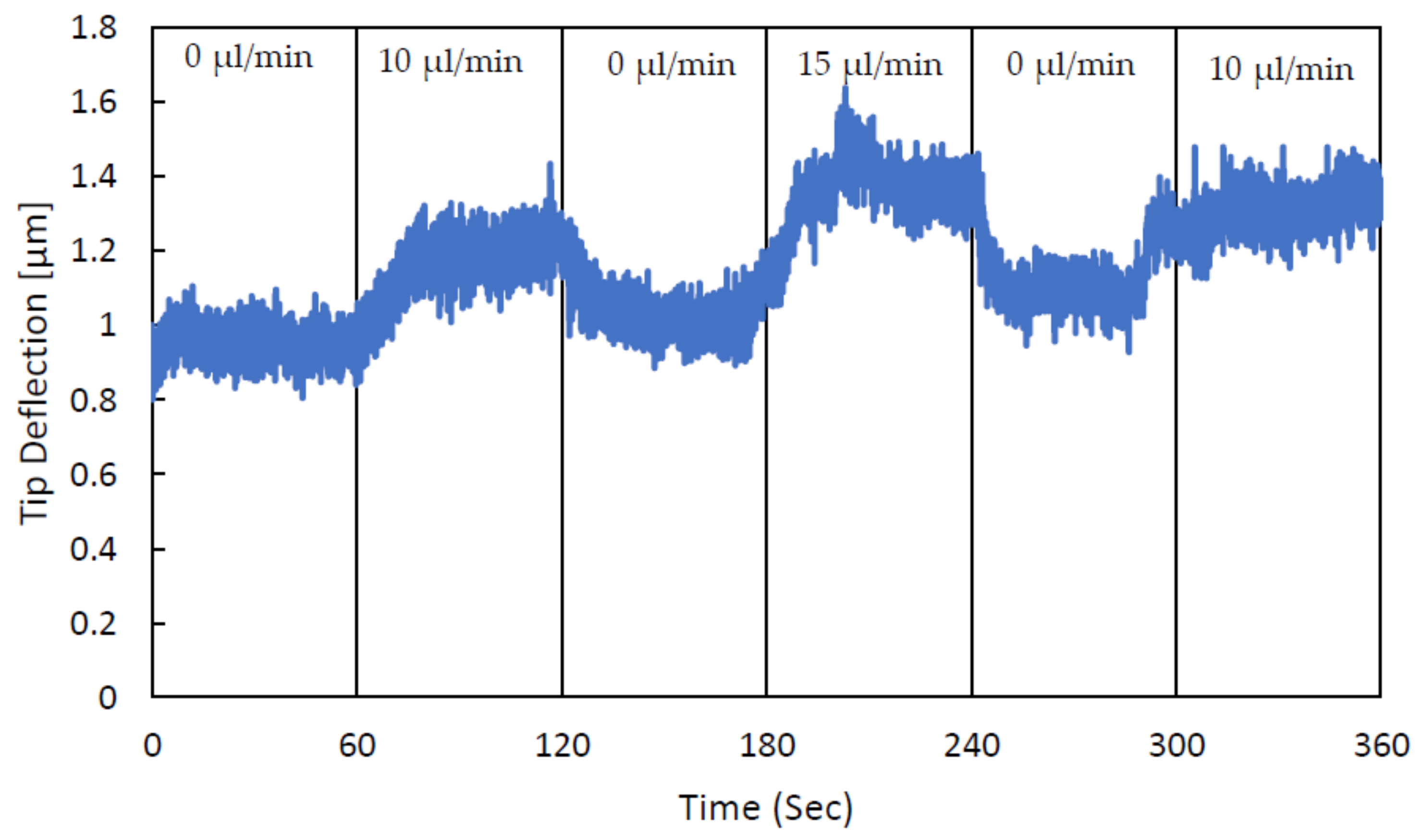
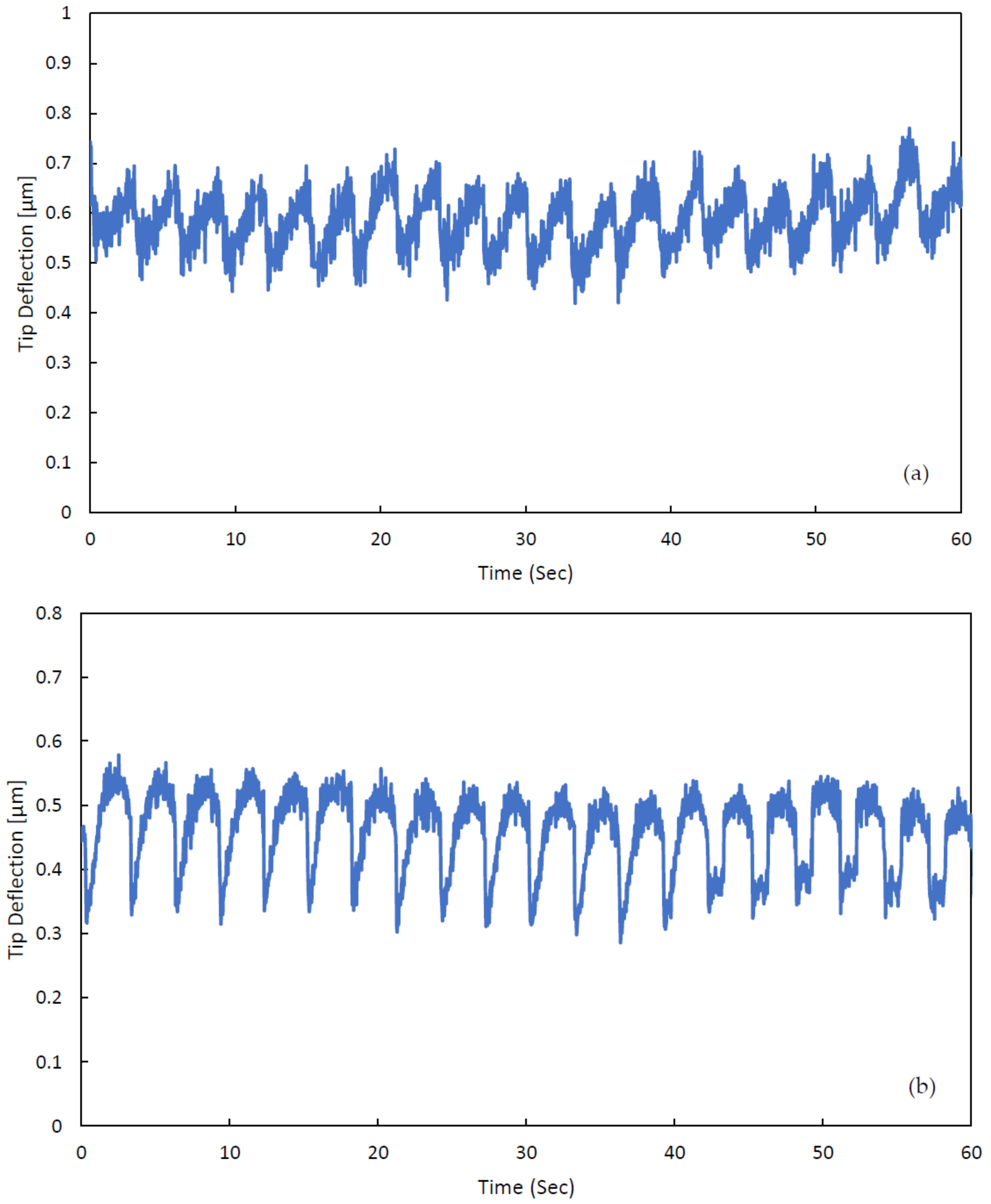
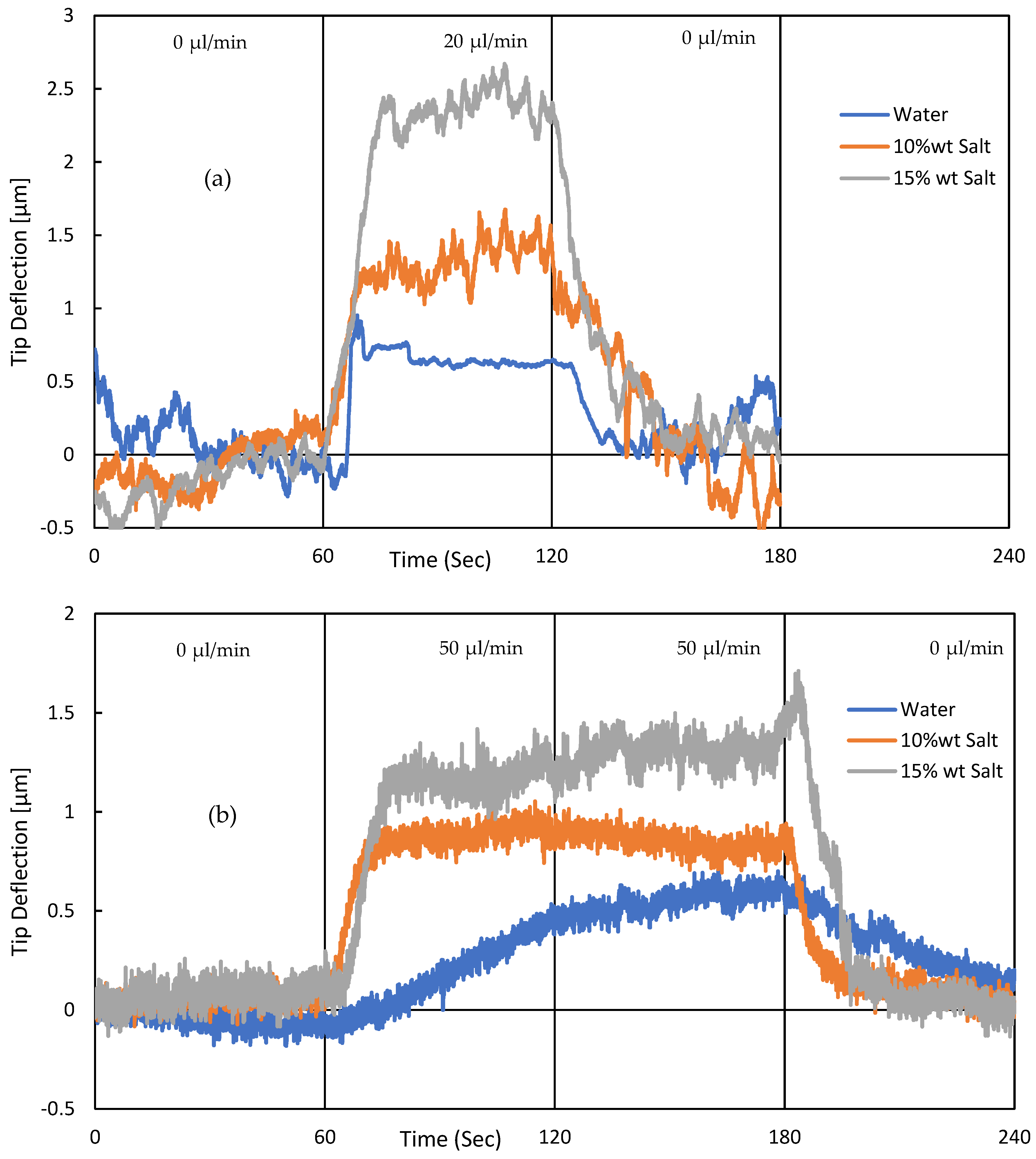
3. Experimental Validation of the SPMF3

An experiment of injecting water with different flow rates has been performed to validate the sensitivity of fabricated 3D suspended microchannel to flow forces. The microcantilever deflections were measured by an optical laser-based deflection measurement system shown in Figure 11.
In this measurement system, reflected laser light from the shiny cantilever tip was detected with PSD, and its displacement history was recorded in a data logger. Since the laser, microcantilever, and PSD are on the same plane, the displacements of the reflected laser light can be transformed into microcantilever deflections using a geometrical formula [32].
In order to study the microchannel’s dimensions impact on the sensitivity of the fabricated microsystem, two SPMF3 with different microchannel dimensions were fabricated for this experiment. The first SPMF3 sample has a channel size of 400 × 100 µm2, respectively, and the second one has a channel size of 200 × 100 µm2. A syringe pump was employed to inject DI water with different flow rates from 0 to 20 µL/min into SPMF3 samples. As shown below, Figure 12 and Figure 13, both SPMF3 samples had high sensitivity to flow forces when a fluid passed through the suspended microchannel and nozzle.
In the next experiment, a peristaltic pump was used to investigate the sensitivity of fabricated SPMF3 under dynamic loads such as a pulsating flow. The peristaltic pump speed is fixed at 2 rpm, and it is connected to the both fabricated SPMF3 systems with different microchannel dimensions of 200 × 100 µm2 and 400 × 100 µm2 (width by depth). According to measured cantilever deflections shown in Figure 14, the SPMF3 systems are sensitive to dynamic loads of pulsating flows generated by rollers of the peristaltic pump. Here, the microfluidic system was tested at 2 rpm pump speed that generated flow pulses of 0.33 Hz due to 10 rotating rollers of the pump.
In the next experiment, DI water with different concentrations of salt varying from 0–15% of weight was injected into the two SPMF3 samples with different microchannel dimensions. The intention was to verify the sensitivity of SPMF3 relative to various fluid properties such as density and viscosity. Varying salt concentration in water results in different fluid density and viscosity, as shown in Table 2
According to the experimental results shown in Figure 15, variation in fluid properties through the addition of salt can be detected using this microsystem. This experiment has been repeated for both SPMF3 samples with 400 × 100 µm2 and 200 × 100 µm2 (width by depth) microchannel dimensions. As confirmed in this figure, SPMF3 can be employed for different bio-fluid detection applications. Further results of such experiments in fluid detection have been examined and published by the current authors [22].

4. Conclusions

Polydimethylsiloxane (PDMS) has shown promising results in 3D microfluidics fabrication due to its capability for multi-layer fabrication. Each layer may have microchannels, valves, pumps, and holes and can be aligned and bonded to a single microfluidic system. In this paper, the fabrication process details of a 3D-suspended microfluidics with issues and solutions were presented. SPMF3 works based on the flow forces created along the microchannel when the flow direction is modified. These forces can be optimized through the design and dimensional modification of microchannels and nozzle.
During this fabrication, some fundamental issues were observed, such as bonding adhesion, trapped air-bubble between PDMS layers, and microparticles clogging, as well as some minor issues such as microchannel and nozzle misalignment and nozzle-finishing quality. These major issues of bonding strength, trapped air, and particles clogging were addressed using optimized PDMS curing temperature from 90 °C to 65 °C, adding an optimum number of air-vent microchannels to PDMS layers and reducing microparticle flow rates by using a diluted microparticle solution with TWEEN20, respectively.
Finally, the sensitivity of the SPMF3 was examined in different conditions such as step-flow rate variation and dynamic flow (Peristaltic pump) and detecting variations in fluid properties (salt addition). Based on the experimental results, SPMF3 can be employed as a bio-fluid detection platform, which is able to differentiate fluid properties as well as its flow rate in either steady or transient flows.

Author Contributions

M.P. conceived the study. M.M. conducted experiments and performed analysis. M.M. and E.Y.M. performed microfabrication experiments and prepared the results. M.M. and M.P. wrote the manuscript. M.M., E.Y.M., M.P. and J.D. participated in the preparation and editing of the manuscript. All authors have read and agreed to the published version of the manuscript.

Funding

Financial support from NSERC Discovery and Concordia University Research Chair of MP and NSERC Discovery of JD is acknowledged.

Institutional Review Board Statement

Not applicable.

Informed Consent Statement

Not applicable.

Data Availability Statement

Not applicable.

Conflicts of Interest

The authors declare no conflict of interests.

References

  1. Luka, G.; Ahmadi, A.; Najjaran, H.; Alocilja, E.; DeRos, M.; Wolthers, K.; Malki, A.; Aziz, H.; Althani, A.; Hoorfar, M. Microfluidics Integrated Biosensors: A Leading Technology towards Lab-on-a-Chip and Sensing Applications. Sensors 2015, 15, 30011–30031. [Google Scholar] [CrossRef] [PubMed] [Green Version]
  2. Prakash, S.; Pinti, M.; Bhushan, B. Theory, fabrication and applications of microfluidic and nanofluidic biosensors. Phil. Trans. R. Soc. A 2012, 370, 2269–2303. [Google Scholar] [CrossRef] [PubMed]
  3. Harrison, D.J.; Manz, A.; Fan, Z.; Ludi, H.; Widmer, H.M. Capillary electrophoresis and sample injection systems integrated on a planar glass chip. Anal. Chem. 1992, 64, 1926–1932. [Google Scholar] [CrossRef]
  4. Jacobson, S.C.; Hergenroder, R.; Koutny, L.B.; Warmack, R.J.; Ramsey, J.M. Effects of injection schemes and column geometry on the performance of microchip electrophoresis devices. Anal. Chem. 1994, 66, 1107–1113. [Google Scholar] [CrossRef]
  5. Tong, Q.-Y.; Gosele, U. Semiconductor Wafer Bonding: Science and Technology; Wiley: New York, NY, USA, 1999. [Google Scholar]
  6. Sparks, D.; Queen, G.; Weston, R.; Woodward, G.; Putty, M.; Jordan, L.; Zarabadi, S.; Jayakar, K. Wafer-to-wafer bonding of nonplanarized MEMS surfaces using solder. J. Micromech. Microeng. 2001, 11, 630–634. [Google Scholar] [CrossRef]
  7. Iyer, S.S.; Auberton-Herve, A.J. Silicon Wafer Bonding Technology for VLSI and MEMS; INSPEC: London, UK, 2002. [Google Scholar]
  8. Xia, Y.; Whitesides, G.M. Soft lithography. Annu. Rev. Mater. Sci. 1998, 28, 153–184. [Google Scholar] [CrossRef]
  9. Quake, S.R.; Scherer, A. From micro- to nanofabrication with soft materials. Science 2000, 290, 1536–1540. [Google Scholar] [CrossRef] [Green Version]
  10. Wu, H.; Odom, T.W.; Chiu, D.T.; Whitesides, G.M. Fabrication of complex three-dimensional microchannel systems in PDMS. J. Am. Chem. Soc. 2003, 125, 554–559. [Google Scholar] [CrossRef]
  11. Samel, B.; Chowdhury, M.K.; Stemme, G. The fabrication of microfluidic structuresby means of full-wafer adhesive bondingusing a poly(dimethylsiloxane) catalyst. J. Micromech. Microeng. 2007, 17, 1710–1714. [Google Scholar] [CrossRef]
  12. McDonald, J.C.; Whitesides, G.M. Poly(dimethylsiloxane) as a material for fabricatingmicrofluidic devices. Acc. Chem. Res. 2002, 35, 491–499. [Google Scholar] [CrossRef]
  13. Miranda, I.; Souza, A.; Sousa, P.; Ribeiro, J.; Castanheira, E.M.; Lima, R.; Minas, G. Properties and applications of PDMS for biomedical engineering: A review. J. Funct. Biomater. 2021, 13, 2. [Google Scholar] [CrossRef] [PubMed]
  14. Gonçalves, I.M.; Rodrigues, R.O.; Moita, A.S.; Hori, T.; Kaji, H.; Lima, R.A.; Minas, G. Recent trends of biomaterials and biosensors for organ-on-chip platforms. Bioprinting 2022, 26, e00202. [Google Scholar] [CrossRef]
  15. Femmer, T.; Jans, A.; Eswein, R.; Anwar, N.; Moeller, M.; Wessling, M.; Kuehne, A.J. High-Throughput Generation of Emulsions and Microgels in Parallelized Microfluidic Drop-Makers Prepared by Rapid Prototyping. ACS Appl. Mater. Interfaces 2015, 7, 12635–12638. [Google Scholar] [CrossRef] [PubMed]
  16. Femmer, T.; Kuehne, A.J.; Wessling, M. Print your own membrane: Direct rapid prototyping of polydimethylsiloxane. Lab Chip 2014, 14, 2610–2613. [Google Scholar] [CrossRef] [PubMed]
  17. Jans, A.; Lölsberg, J.; Omidinia-Anarkoli, A.; Viermann, R.; Möller, M.; De Laporte, L.; Wessling, M.; Kuehne, A.J. High-throughput production of micrometer sized double emulsions and microgel capsules in parallelized 3D printed microfluidic devices. Polymers 2019, 11, 1887. [Google Scholar] [CrossRef] [PubMed] [Green Version]
  18. Grilli, S.; Coppola, S.; Nasti, G.; Vespini, V.; Gentile, G.; Ambrogi, V.; Carfagna, C.; Ferraro, P. Hybrid ferroelectric–polymer microfluidic device for dielectrophoretic self-assembling of nanoparticles. RSC Adv. 2014, 4, 2851–2857. [Google Scholar] [CrossRef]
  19. Coppola, S.; Nasti, G.; Todino, M.; Olivieri, F.; Vespini, V.; Ferraro, P. Direct writing of microfluidic footpaths by pyro-EHD printing. ACS Appl. Mater. Interfaces 2017, 9, 16488–16494. [Google Scholar] [CrossRef]
  20. Wu, H.; Huang, B.; Zare, R.N. Construction of microfluidic chips using polydimethylsiloxane for adhesive bonding. Lab Chip 2005, 5, 1393–1398. [Google Scholar] [CrossRef]
  21. Eddings, M.A.; Johnson, M.A.; Gale, B.K. Determining the optimal PDMS–PDMS bonding technique for microfluidic devices. J. Micromech. Microeng. 2008, 18, 067001. [Google Scholar] [CrossRef]
  22. Marzban, M.; Packirisamy, M.; Dargahi, J. 3D Suspended Polymeric Microfluidics (SPMF3) with Flow Orthogonal to Bending (FOB) for Fluid Analysis through Kinematic Viscosity. Appl. Sci. 2017, 7, 1048. [Google Scholar] [CrossRef] [Green Version]
  23. Marzban, M.; Dargahi, J.; Packirisamy, M. Flow force augmented 3D suspended polymeric microfluidic (SPMF3) platform. Electrophor. Microfluid. Miniat. 2019, 40, 388–400. [Google Scholar] [CrossRef] [PubMed]
  24. Marzban, M.; Dargahi, J.; Packirisamy, M. Rigid and Elastic Microparticles Detection Using 3D Suspended Polymeric Microfluidics (SPMF3) Sensor. IEEE Sens. 2018, 18, 5674–5684. [Google Scholar] [CrossRef]
  25. Marzban, M.; Packirisamy, M.; Dargahi, J. Parametric study on fluid structure interaction of a 3D suspended polymeric microfluidics (SPMF3). Micorsyst. Technol. 2018, 24, 2549–2559. [Google Scholar] [CrossRef]
  26. Moghadam, E.Y.; Packirisamy, M. Increase of Sensitivity in 3D Suspended Polymeric Microfluidic Platform through Lateral Misalignment. Waset Acad. Sci. 2017, 11, 1896–1901. [Google Scholar] [CrossRef]
  27. McDonald, J.C.; Duffy, D.C.; Anderson, J.R.; Chiu, D.T.; Wu, H.; Schueller, O.J.; Whitesides, G.M. Fabrication of microfluidic systems in poly(dimethylsiloxane). Electrophoresis 2000, 21, 27–40. [Google Scholar] [CrossRef]
  28. Dendukuri, D.; Doyle, P.S. The Synthesis and Assembly of Polymeric Microparticles Using Microfluidics. Adv. Mater. 2009, 21, 4071–4086. [Google Scholar] [CrossRef]
  29. Tan, W.H.; Takeuchi, S. A trap-and-release integrated microfluidic system for dynamic microarray applications. Proc. Natl. Acad. Sci. USA 2007, 104, 1146–1151. [Google Scholar] [CrossRef] [Green Version]
  30. Karlsson, J.; Haraldsson, T.; Sandström, N.; Stemme, G.; Russom, A.; van der Wijngaart, W. On-Chip Liquid Degassing with Low Water Loss. In Proceedings of the 14th International Conference on Miniaturized Systems for Chemistry and Life Sciences, Groningen, The Netherlands, 3–7 October 2010. [Google Scholar]
  31. Wyss, H.M.; Blair, D.L.; Morris, J.F.; Stone, H.A.; Weitz, D.A. Mechanism for clogging of micro-channels. Phys. Rev. 2006, 74, 061402. [Google Scholar]
  32. Beaulieu, L.; Godin, M.; Laroche, O.; Tabard-Cossa, V.; Grutter, P. A complete analysis of the laser beam deflection systems used in cantilever-based systems. Ultramicroscopy 2007, 107, 422–430. [Google Scholar] [CrossRef]
  33. Vliet, T.V.; Walstra, P. Relationship between viscosity and fat content of milk and cream. Texture Stud. 1980, 11, 65–68. [Google Scholar] [CrossRef]
Figure 1. Three layers of the suspended microfluidics.
Applsci 12 04626 g001
Figure 2. Schematic view of microfluidic system fabrication process using soft lithography; (a) mold fabrication step using soft lithography; (b) microchannel fabrication step using polymeric material; (c) bonding step using oxygen plasma bonding.
Applsci 12 04626 g002
Figure 3. Negative masks printed for photo lithography process: (a) nozzle mask, (b) microcantilever mask, and (c) microchannel mask.
Applsci 12 04626 g003
Figure 4. The final fabricated molds: (a) nozzle mold and (b) microchannel mold.
Applsci 12 04626 g004
Figure 5. The PDMS layers fabrication processes: (a) pouring PDMS on the mold; (b) applying pressure using grippers; (c) PDMS layer after curing process; (d) detaching PDMS layer from the mold.
Applsci 12 04626 g005
Figure 6. (a) PDMS layers fabricated on glass slides; (b) PDMS layers bonded together between glass slides; (c) final 3D suspended microfluidics; (d) schematic view of bonding sequence of the main layers (MLT, NL, and MLB) to create SPMF3.
Applsci 12 04626 g006aApplsci 12 04626 g006b
Figure 7. Schematic view of the microchannel layer of SPMF3 with two air-vent microchannels.
Applsci 12 04626 g007
Figure 8. The effect of air-vent microchannel on tapped air-bubble size; (a) microchannel layer without air-vent channel; (b) microchannel layer with 300 µm air-vent channel; (c) microchannel layer with 500 µm air-vent channel.
Applsci 12 04626 g008
Figure 9. Polystyrene microparticles stuck inside the microfluidic channels: (a) particles clogging in the SPMF3; (b) particles clogging in a cross microchannel used for particle injection during some experiments.
Applsci 12 04626 g009
Figure 10. (a) Top view of the three microchannels and nozzle layers with an undesired offset; (b) side view of a fabricated SPMF3 with undesired offset between layers.
Applsci 12 04626 g010
Figure 11. Laser displacement measurement system.
Applsci 12 04626 g011
Figure 12. The sensitivity experiment of 3D suspended microcantilever has a 400 × 100 µm2 (width and depth) channel with various step flows of 10-15-20-15-10-0 µL/min. The syringe pump flow rate changes every 60 s, and the SPMF3 responds to this new flow rate.
Applsci 12 04626 g012
Figure 13. Sensitivity experiment of 3D suspended microcantilever, which has a 200 × 100 µm2 (width and depth) channel with various step flows of 0-10-0-15-0-10 µL/min. The syringe pump flow rate changes every 60 s, and SPMF3 responds to this new flow rate.
Applsci 12 04626 g013
Figure 14. SPMF3 response to dynamic load of a Peristaltic pump with a fixed speed of 2 rpm, which was generating flow pulses of 0.33 Hz due to 10 rotating rollers of the pump, i.e., 20 pulses in 60 s. (a) The SPMF3 sample has a microchannel of 400 × 100 µm2 (width and depth). (b) The SPMF3 sample has a microchannel of 200 × 100 µm2.
Applsci 12 04626 g014
Figure 15. Sensitivity experiment of SPMF3 to various fluid properties. A water and salt mixture with different salt concentrations has been used here. (a) The SPMF3 sample has a microchannel of 400 × 100 µm2 (width and depth). (b) The SPMF3 sample has a microchannel of 200 × 100 µm2.
Applsci 12 04626 g015
Table 1. Parameters used for suspended microfluidics simulation [25], where L denotes length, W denotes width, and T denotes thickness.
Cantilever Size,
L, W, T (µm)
Microchannel Size,
W, T (µm)
Nozzle Size,
W, L (µm)
6000 × 2000 × 600200 × 100200 × 400
Table 2. The 3D microfluidics behavior against variations in fluid properties at 21 °C [33].
Salt wt %Density (kg/m3)Viscosity (cP)
0%9991.002
10%10701.193
15%11101.350
Publisher’s Note: MDPI stays neutral with regard to jurisdictional claims in published maps and institutional affiliations.

