Featured Application
The technical indexes obtained from this paper can provide a reference for mortar disengagement repairing, which is conductive to relieving the track maintenance pressure and saving maintenance cost.
Abstract
To investigate the influences of through-transverse mortar disengagement with different lengths and heights on the dynamic responses of vehicle and track systems under the high frequency train loads, a coupled rigid vehicle–flexible track multi-body dynamics (MBD) model with mortar disengagement was established in SIMPACK platforms with the help of ANSYS software. The results indicate that when the mortar disengagement length is no more than 1 m, the responses of vehicle and track systems are hardly influenced by mortar disengagement with an increase rate of no more than 10% except for the slab displacement. When LMD reaches 1.5 m, the maximum slab displacement exceeds the safety limit of 0.5 mm. The vertical wheel–rail contact force and the rail displacement exceed the safety limit with the mortar disengagement length of 2 m and the mortar disengagement height of 1.5 mm. The most increase rates induced by mortar disengagement are 190% and 272% with regards to the slab displacement and the longitudinal tension stress of slab, respectively, which is significantly detrimental to the service life of slab. The proposed approach has the potential to preliminarily determine the critical mortar disengagement size, which is conductive to relieving the pressure of track maintenance while ensuring the service life of track structures and the operation safety and riding comfort of the vehicle.
1. Introduction
The China railway track system II (CRTS II) ballastless slab track has been widely applied to high-speed railway due to the superior stability, smoothness, reliability and durability [1,2]. CRTS II slab track consists of rails, fasteners, prefabricated slab, the emulsified cement asphalt (CA) mortar layer, concrete base and subgrade [3]. The main functions of CA mortar layer are the leveling, support and amortization. However, CA mortar is one of the weakest parts for its particular material, harsh natural environment, repeated temperature loads and high-frequency train loads [4,5,6,7,8]. Specifically, to equip the CA mortar with a semi-rigid high performance with the combined merits of high strength and good viscosity, the constituent materials of it are sand, cement, emulsified asphalt and admixtures [3]. For the CRTS II ballastless track system, CA mortar is directly poured into the gap between the slab and base with a thickness of 30 mm. As an organic-inorganic nonmetal composite material, CA mortar is prone to aging damage when exposed to the air and sun [4]. Meanwhile, the repeated loads induced by the temperature difference between day and night is crucial to the fatigue damage evolution of CA mortar [7]. During its service period, CA mortar is subjected to the high-frequency train loads and is prone to fatigue failure [8]. Therefore, the interface damage between slab and mortar, known as the mortar disengagement, is a common and incident track disease in CRTS II slab track, as shown in Figure 1 [9].
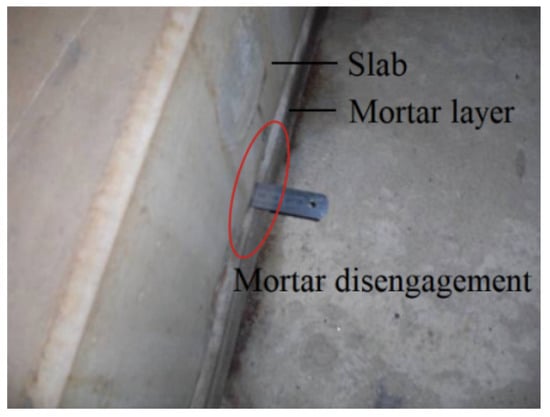
Figure 1.
Diagram of the mortar disengagement [9].
Mortar disengagement directly causes the insufficient support under the slab and worsens the track dynamic evenness, which further affects the vibration performance of vehicle systems [5,9]. It is necessary to repair the mortar disengagement before it develops to the stage that is detrimental to the track service life and the operation safety and riding comfort of the operation vehicle. However, the main disadvantage of CRTS II slab track is the difficulty in maintenance [10]. If mortar disengagement is repaired once detected, the workload of track maintenance will be increased greatly due to the wide application of the CRTS II ballastless slab track. Therefore, it is necessary to study the impact of mortar disengagement on the vehicle and track performances under the high frequency train loads for preliminarily determining the critical value of mortar disengagement size. Then, on the premise of not endangering track service life, vehicle operation safety and ride comfort, the appropriate track maintenance criteria can be put forward to alleviate the pressure of track maintenance.
Numerous studies on the mortar disengagement in ballastless slab track mainly focused on the mechanism of interface damage. Zhou et al. [10] investigated the time-dependent behaviors of track system under the train loads with a 3D finite element (FE) model, which considered the damage deterioration of track structures. The author also explored the initiation and evolution of interlayer damage under the temperature loads by an experimental study [11]. Su et al. [12] analyzed the interface parameters between the slab and mortar layer based on the experimental results to provide reference for the design of CRTS II slab track. Shan et al. [5] employed a special anti-fatigue device to study the damage mechanism and the degradation process of mortar disengagement in CRTS I slab track. Ren et al. [13] analyzed the viscoelastic deformation of the CA mortar by building a solid (FE) model of CRTS I track using ABAQUS software. Zhu et al. [14] probed into the damage evolution and dynamic performance of CA mortar layer under the train loads via a vehicle–slab track coupled model established in ABAQUS. Then, studies on the influences of mortar disengagement on the track system were conducted. Ren et al. [8,15] researched the influence of mortar disengagement on the concrete damage distribution and mechanical responses of slab through developing a CRTS I slab track system. Since the performances of vehicle system are also deteriorated when the mortar damage develops to a certain extent, the vehicle responses are considered when studying the effect of CA mortar disengagement. The studies usually [16,17,18,19,20,21] established a vertical vehicle–slab track model and discussed the effect of CA mortar disengagement with different lengths and heights on the dynamic performances of vehicle and track structures. Studies based on the experimental results were also carried out to explore the effects of mortar disengagement on the responses of vehicle and track systems. Yang et al. [22,23] analyzed the vibration characteristics of the vehicle and CRTS I slab track under different mortar disengagement conditions through field test and theoretical analysis. Ren et al. [24] investigated the influence of mortar damage on the track system by numerical and experimental results to recommend values for criteria of mortar disengagement. Both the mortar disengagement in ballastless slab track and unsupported sleepers in ballasted track are local instabilities, which exert similar influence on the vibration responses of vehicle and track structures. Sysyn et al. [25,26] comprehensively studied the effects of unsupported sleepers on the interaction behaviors in the void and neighbor zones via numerical simulation and experimental measurements.
According to the literature review, the existing investigations mainly focus on the damage mechanism of CA mortar and the influences of mortar disengagement on the track carry capacities of CRTS I slab track. However, compared with the mortar in CRTS I slab track, the elastic modulus of mortar in CRTS II slab track is much larger. The equivalent stiffness of mortar in CRTS II slab track is much greater than that in CRTS I slab track, which leads to more significant influences on vehicle and track systems due to mortar disengagement [5]. Meanwhile, the longitudinal stress of slab and compressive stress of mortar layer in the past investigations are seldom mentioned, which are adversely affected by local mortar disengagement seriously [27]. Most investigations simulated the mortar layer as spring-damper elements, leading to the difficulty in obtaining the stress of mortar layer [20,28]. Additionally, the research technology mostly relies on experiments or theoretical methods. Disadvantages of experiments are the long test cycle, high cost and tendency to be affected by environment [29,30]. Moreover, it is not feasible to set up mortar disengagement with different lengths and heights in the field experiment. Theoretical analysis introduces considerable equilibrium equations, which usually need an iterative producer and small integration step of time to obtain converged solutions. Moreover, the algorithm for compiling the programmer is merely detailed in references [31]. Therefore, both experiments and theoretical analysis have great limitations.
As a professional multi-body simulation (MBS) software package for railway vehicle, the efficiency of vehicle modeling is greatly improved through the SIMPACK platform [32]. SIMPACK cannot directly formulated the flexible track, which is initially established in a finite element (FE) analysis software ANSYS. With the help of ANSYS, the flexible track structures are conveniently established, and the calculation time is shortened through substructure analysis. By employing mature software packages, the modeling efficiency is evidently improved, and the visualization of the simulation model is realized as well.
This paper is dedicated to exploring the influences of mortar disengagement on the dynamic performances of vehicle system and carrying capacities of track structures, utilizing a rigid vehicle–flexible track model established in SIMPACK with the help of the ANSYS platform. The simulation model is performed with different mortar disengagement conditions. Specific evaluation indicators with different lengths and heights of mortar disengagements are considered including the vertical wheel–rail contact force, the wheel load reduction rate, the vertical acceleration of car body, the vertical displacements of track structures, the longitudinal tension stress of slab and the compressive stress of the mortar layer. The analysis determines a critical value of the mortar disengagement size. The critical value can provide a reference for track maintenance of CRTS II ballastless slab tracks to save the maintenance costs and avoid safety accident, simultaneously.
The remainder of this paper is organized as follows. Described in Section 2 is the establishment method of the rigid vehicle–flexible track coupled dynamics model with mortar disengagement in detail. In Section 3, effects of mortar disengagement with different lengths and heights on dynamic performances of vehicle and track systems are analyzed comprehensively. Section 4 gives the conclusion.
2. Establishment of the Rigid Vehicle–Flexible Track Coupled Dynamics Model
A comprehensive simulation model of the rigid vehicle and flexible track with mortar disengagement is formulated in the SIMPACK platform. The flexible track model comprising the rail, slab, mortar layer, concrete base, fastener and subgrade is initially established in ANSYS. Then, the mesh and substructuring data files from the FE model are integrated with the rigid vehicle via the FE and MBD interface of SIMPACK. By employing the mature software packages, the modeling efficiency is evidently improved and the visualization of the simulation model is realized. The schematic view of the dynamics model with mortar disengagement is shown in Figure 2.
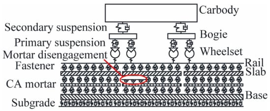
Figure 2.
Schematic view of the vehicle–track coupled model with mortar disengagement.
2.1. Establishment of the Rigid Vehicle Model
The rigid vehicle model is developed composed of a carboy, two bogies and four wheelsets. Each component contains 5 degrees of freedom (DOFs), that is, motions along the lateral (y) and vertical (z) axes and rotations along the longitudinal (), lateral () and vertical () axes. The primary suspension coupling the wheelset and bogie as well as the secondary suspension connecting the bogie and car body are represented by parallel combinations of linear spring-damper elements along three translational (X, Y, Z) axes.
2.2. Establishment of the Flexible Track Model
The FE models of track structures, containing rail, slab, CA mortar and base, are developed in ANSYS utilizing the solid elements. The 6.45 m long flexible track, as long as the length of one unit slab, comprises 22,704 elements, The FE track structures are subsequently reduced by substructure technique based on the Guyan reduction theory. The subgrade is equivalent to spring-damper elements, and the equivalent stiffness depends on its elastic modulus and thickness [33]. The rail, slab, CA mortar and base are connected by linear spring-damper elements in SIMPACK. In the mortar disengagement zone, the spring-damper elements are described by clearance springs, which provide support function only when the slab displacement is greater than the height of mortar disengagement (HMD). The action principle of clearance spring is illustrated in Figure 3, where denotes the HMD.
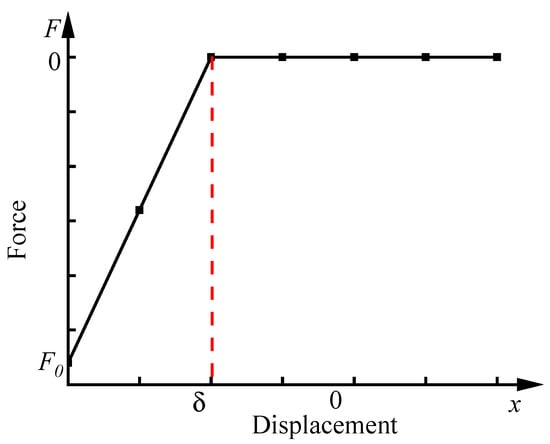
Figure 3.
Action principle of the clearance spring.
The workflow of the rigid vehicle–flexible track simulation model includes three stages: the discretization of track structures from geometries into FE models; the substructure analysis of FE models; the integration of the flexible track with rigid vehicle.
2.2.1. Discretization of Track Structures into FE Models
The rail, slab, CA mortar and base are meshed into FE models containing the information of nodes, elements and material properties. Figure 4 shows the FE model of the track system and the element parameters are detailed in Figure 4b. The meshing size of the FE model is vital to the simulation accuracy and computation time. The computation time will increase if the mesh size is too small. To facilitate connections and balance the calculation time and simulation accuracy, the mesh elements of the rail, slab, mortar and base have the same longitudinal length of 50 mm. In Figure 4b, , , , , and .

Figure 4.
FE model of slab track structure. (a) Sketch of the FE models of the structural system. (b) Detailed parameters of the mesh elements.
2.2.2. Substructure Analysis of FE Models
The flexible track structures contain a large number of nodes and elements. Thus, many degrees of freedom (DOFs) are introduced to the MBD simulation, and the computation time will increase greatly. To shorten the calculation time, the substructure analysis of FE models is conducted based on Guyan’s reduction theory, which is a process of condensing a group of elements into a super element by matrix [34,35]. The dynamic equilibrium equation of the dynamic model is:
where , and are the mass matrix, stiffness matrix and damping matrix, respectively, and , and are the displacement matrix, velocity matrix and the load matrix, respectively.
Nodes of FE models, which are selected to represent all node information, are denoted as master nodes. The others are called slave nodes [36]. Assuming that there are DOFs of master nodes and DOFs of slave nodes, the matrix form of Equation (1) is:
where , , and are the stiffness matrices with sizes of , , and in turn, and are the corresponding mass matrix and damping matrix, respectively, and is the load vector acting on the master nodes.
Guyan’s reduction theory is a static transformation based on . Then, we can get:
Equation (4) can be obtained by calculating the first and second derivative of Equation (3):
Putting Equation (4) into Equation (2) to get Equation (5) for :
To balance Equations (3) and (5), coefficients of and should be zero. That is:
Whether Equation (6) can be satisfied or not depends on the selection of master nodes of the FE models. Considering the significance of track structural shapes, the mounting locations of fasteners and the connection positions between slab and mortar layer as well as between mortar layer and base, simultaneously shortening the computational time, a total of 602, 600, 560 and 448 master nodes of the rails, slabs, mortar layer and concrete base are selected with the length of flexible track being 25.95 m.
The modal analysis of FE models of track structures before and after substructure analysis was conducted. The 7–14 order modal frequencies of FE models and the corresponding reduced models are listed in Table 1. It clearly shows that the frequency differences between the unreduced FE models and reduced models are negligible. Therefore, the master nodes of the track structures selected in this paper are appropriate.

Table 1.
Modal frequencies of the track structures.
The modal superposition method is adopted to account for the contributions of the track structural modes to the vibration behavior of the coupled system, as reported in many studies [37,38]. The cut-off frequency exerts a great influence on the computation time and high cut-off frequency is prone to causing non convergence. As the direct carrier withstanding the medium and high frequency impact of the wheel–rail contact, the medium and high frequencies of flexible rails must be retained. Meanwhile, considering the attenuation effect of the fastener system and the CA mortar layer on the vibration transmission of the wheel–rail system, the cut-off frequencies of the rail, slab, CA mortar layer and the concrete base are 800 Hz, 200 Hz, 100 Hz and 200 Hz, respectively [39].
2.2.3. The Integration of the Rigid Vehicle and Flexible Track Systems
The flexible track structures are introduced into SIMPACK platform by the interface of FE and MBD. The mesh and substructuring data files of rails are transferred into SIMPACK by the ‘FlexTrack’ module, and that of slab, mortar layer and base are introduced into SIMPACK by the ‘FlexBody’ module. The contact forces at the wheel–rail interface are formulated by identifying the contact points through analyses of the wheel–rail contact geometry. The wheel–rail contact force model is developed considering the CHN60 rail profile together with the S1002CN tread profile. The normal and the tangential forces developed at the wheel–rail contact points are formulated based on the Hertz theory and the FASTSIM algorithm [40]. Finally, a combined FE-MBS representation of the rigid vehicle–flexible track simulation model is developed in SIMPACK platform.
2.3. Validation of the Simulation Model
The China Railways High-speed (CRH) electrical multi-units (EMUs) trailer and the CRTS II slab track are referenced with their detailed parameters shown in Table A1 and Table A2 of the Appendix A [41]. The simulation model is performed at a constant forward speed of 300 km/h. The track unevenness is measured from the 4500 m long segment of a high-speed railway track in China (denoted as the WuGuang track), as mentioned in the literature [42]. The track irregularities in time and frequency domains are displayed in Figure 5. As illustrated in Figure 5, the measured data show peak deviations of about 4 mm and 5 mm in the vertical and lateral rail profiles, respectively. The wave lengths of the measured vertical and lateral irregularities are mainly concentrated in 2–200 m and 4–300 m, respectively. The WuGuang track irregularity is adopted in the model to more truly simulate the operating conditions of vehicles.
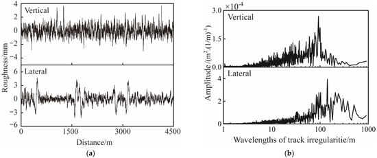
Figure 5.
WuGuang track irregularities: (a) Time histories of track irregularities; (b) Frequency domain of track irregularities.
In the MBD modeling process, the spring-damper elements are simulated as two node elements. The force developed by the elastic element is related to the relative motion across nodes and , such that:
where and represent the elastic element forces acting on nodes and , and denote the stiffness and damper of the element along axis , and indicate the displacements at the nodes and , while and are the corresponding velocities.
The Fulcrum reaction force of rail can be determined according to Equation (7). Since this study focuses on utilizing the maximum dynamic responses of vehicle and track structures with different mortar disengagement sizes to evaluate the influence of mortar disengagement on system performances, the maximum dynamic responses of the simulation model without mortar disengagement are obtained and compared with the results reported in references [2,6,43,44] to validate the correctness of the simulation model established in this paper. The comparison is illustrated in Table 2. The simulation results in this paper are not completely consistent with those reported in other literatures. However, the differences observed between them are relatively small and are mainly caused by track irregularities and parameters of vehicle and track systems. Therefore, the simulation model established in this paper is verified and can be used to study the impact of mortar disengagement on dynamic performances of the vehicle and track systems.

Table 2.
Comparison of the simulation results of this paper with the results of other papers.
2.4. Mortar Disengagement Conditions
According to site investigations, the mortar disengagement generally occurs in slab end (transverse), slab edge (longitudinal) and slab corner [45], as shown in Figure 6, where the blank zone represents the mortar disengagement. Since mortar disengagements appearing in the slab edge and slab corner hardly affect the performance of vehicle and track systems [18,24], this paper mainly studies the influences of through-transverse mortar disengagement on the vibration responses of the vehicle and track structures.
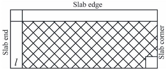
Figure 6.
CA mortar disengagement under one unit slab.
To shorten the calculation time, the length of flexible track is 25.95 m with four slabs in the longitudinal direction. The mortar disengagement is set under the end of the third slab. The mortar disengagement is described by the height () and length () due to the assumption that the mortar exhibits a complete damage along the transverse direction, as displayed in Figure 7. The value of is 0.5, 1, 1.5 and 2 m. The value of is 0.5, 1, 1.5, 2, 2.5, 3, 4 and 5 mm. A total of 33 mortar disengagement conditions are calculated.

Figure 7.
Sketch of the mortar disengagement.
3. Effects of the Mortar Disengagement on Dynamic Performances of the Vehicle–Track System
The through-transverse mortar disengagement mainly affects the vertical dynamic responses of the wheel–rail system; thus, the evaluation indexes of vehicle and track performance considers the vertical wheel–rail contact force, wheel load reduction rate, vertical acceleration of car body, vertical displacements of rail and slab, the longitudinal tensile stress of slab and the compressive stress of mortar layer. For China, the safety limits of vehicle, track and wheel–rail system responses are listed in Table 3 [21,22,46].

Table 3.
Critical values of vehicle and track system responses.
Figure 8 demonstrates the schematic diagram of signal acquisition position for responses of vehicle and track systems. To eliminate the boundary effect, the wheel–rail contact forces are obtained when the first wheelset passes on the second and third slabs, as Section M shows in Figure 8a. When the vehicle runs at a speed of 300 km/h, the wheel–rail contact forces of the first wheelset are collected from 0.15 s to 0.40 s. The further the position of mortar disengagement is away from the fasteners, the smaller the influence of it on the dynamic performances of vehicle and track structures. The signal acquisition positions of the rail and slab displacements are in the longitudinal middle of the mortar disengagement zone directly below the rail, as the points A and B show in Figure 8. Since mortar disengagement leads to the reduction of effective bearing area of the mortar layer under the slab, the mortar layer neighboring the disengagement zone bears greater pressure. The maximum vertical compressive stress of mortar layer is obtained in the zone neighboring the mortar disengagement, such as the Zone Q in Figure 8a. Mortar disengagement results in a large vertical displacement of slab, and further causes the increase of the longitudinal tensile stress of slab in the transition zone with and without mortar disengagement. Thus, the maximum longitudinal tensile stress of slab is obtained in the transition zone, as the Zone P shows in Figure 8a.
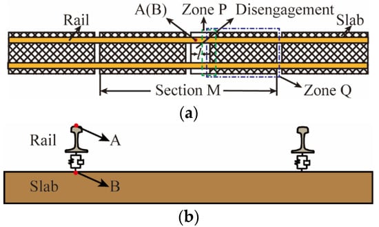
Figure 8.
Schematic diagram of signal acquisition positions: (a) Top view; (b) Main view.
To clearly indicate the changes in the dynamic performance of the wheel–rail system with and without mortar disengagement, the change rate () is defined by Equation (8):
where and are the maximum dynamic responses of vehicle and track structures with and without mortar disengagement, respectively.
3.1. Impacts of Mortar Disengagement on the Vehicle Performances
3.1.1. Evaluation of the Vehicle Operation Safety
The vertical wheel–rail contact force and the wheel load reduction rate are usually exploited to evaluate the vehicle operation safety. The vertical contact force is evidently influenced by the track dynamic unevenness induced by mortar disengagement. Since the wheel load reduction rate is deduced from the vertical wheel–rail contact force, formulated by Equation (9), it is susceptible to the mortar disengagement, as well:
where means the wheel load reduction rate, is the amount of wheel load reduction, is the average wheel load of the left and right wheels and and are the dynamic and static wheel loads, respectively.
The vertical wheel–rail contact forces with and without mortar disengagement are shown in Figure 9. It demonstrates that the amplitudes of wheel–rail force both in the disengagement zone and in the adjacent undamaged zone are significantly affected because of the mortar disengagement. The maximum wheel–rail force appears when the vehicle passes through the disengagement zone. Therefore, in the following analysis, for investigating the influence of mortar disengagement on the wheel–rail system performance, the maximum dynamic responses of vehicle structures are obtained either in the disengagement zone or in the neighboring undamaged zone.
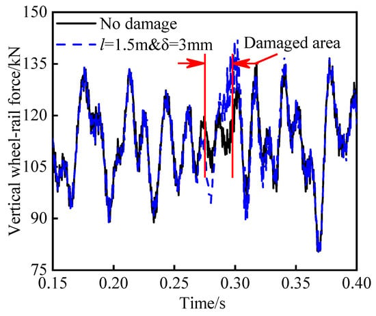
Figure 9.
Vertical wheel–rail contact forces in the time domain.
Figure 10 shows the maxima of the vertical wheel–rail contact forces and wheel load reduction rates with different mortar disengagement lengths (LMDs) and mortar disengagement heights (HMDs). In Figure 10, the maxima of wheel–rail forces and wheel load reduction rates increase with the increase of LMD and HMD. The effect of mortar disengagement on the vertical wheel–rail contact force is basically the same as the wheel load reduction rate. When LMD is greater than 1 m, the wheel–rail contact force and wheel load reduction rate increase apparently with the increase of HMD. For a constant LMD, when HMD reaches a special value, the maximum wheel–rail contact force keeps constant with the increase of HMD. This is because the slab cannot come into contact with the mortar layer when HMD is larger than the special value even though the vehicle passes through the mortar damage zone, and the mortar layer no longer plays a role of support. Thus, the maximum wheel–rail contact force remains basically unchanged with the increase of HMD. The mortar disengagement develops into a mortar void and special values of HMD and LMD are the critical sizes of the mortar void. A mortar void is the result of the further development of mortar disengagement. As the LMD is 0.5 m, 1 m, 1.5 m and 2 m, the corresponding mortar void heights are 1 mm, 1.5 mm, 2 mm and 4 mm, respectively. In the following analysis of some figures, the results of the mortar void will no longer be displayed.
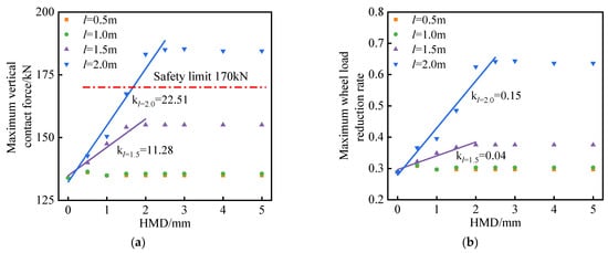
Figure 10.
The maximum safety indexes under different mortar disengagement conditions: (a) Maximum wheel–rail contact force; (b) Maximum wheel load reduction rate.
Figure 10a,b illustrate that when LMD is no more than 1 m, mortar disengagement hardly exerts influence on the maximum wheel–rail contact forces and wheel load reduction rate. The maximum growth rates are only 1.3% and 7.6% with regard to the maximum wheel–rail contact forces and wheel load reduction rate compared with that without mortar disengagement. When LMD is 1.5 m and 2 m, respectively, the maximum wheel–rail contact forces increase by 10.77% and 38.35%, and the maximum wheel load reduction rates increase by 30.35% and 120.83%. Meanwhile, as LMD reaches 2 m and HMD reaches 2 mm, the maximum wheel–rail contact force exceeds the critical value of 170 kN.
When LMD reaches 1.5 m and HMD is no more than 2 mm, the maximum wheel–rail forces and wheel load reduction rates linearly increase with the increase of HMD. The slopes of linear fitting are 11.28 kN/mm and 0.04/mm for the maximum wheel–rail forces and wheel load reduction rates, respectively. When LMD reaches 2 m and HMD is no more than 2.5 mm, the slopes of linear fitting are 22.51 kN/mm and 0.15/mm, respectively. When LMD is 2 m, the growth rate of wheel–rail contact force and wheel load reduction rate with HMD is twice and four times that when LMD is 1.5 m, respectively. With the increase of LMD, the change of the wheel load reduction rate is more obvious than the wheel–rail contact force. Overall, LMD exerts a more conspicuous impact on the vehicle operation safety than HMD.
To ensure the vehicle operation safety, the vertical wheel–rail contact force and the wheel load reduction rate are not allowed exceeding 170 kN and 0.8. Therefore, the mortar disengagement would not damage the vehicle operation safety with LMD being less than 2 m. While LMD reaches 2 m, the HMD shall not exceed 2 mm, preferably 1.5 mm.
3.1.2. Evaluation of the Vehicle Riding Comfort
It is convenient and effective to evaluate the riding comfort of vehicle through the car body acceleration. Figure 11 displays the maximum vertical accelerations of the car body with different LMDs and HMDs. Significant increase lies in the car body acceleration when LMD is 2 m, and the maximum car body acceleration is 0.53 m/s2, which is 1.6 times higher than that without mortar disengagement. As LMDs are no more than 1.5 m, the change rates of maximum car body accelerations are less than 10%. Therefore, mortar disengagement does not threaten the riding comfort of vehicle in all calculated conditions.
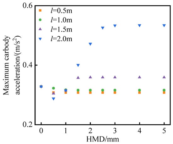
Figure 11.
Vertical car body accelerations under different mortar disengagement conditions.
3.2. Impacts of Mortar Disengagement on the Track Performances
3.2.1. Displacements of Track Structures
Figure 12 compares the rail displacements under different mortar disengagement conditions in the time domain. The rail deflection peaks present the passage of four wheelsets of a vehicle. In the figure, the dynamic behavior of rail depends on LMD and the amplitudes of rail displacements increase with the increase of LMD. Meanwhile, Figure 12 also implies that only the amplitude of rail displacement increases when LMD is less than 1 m. However, with LMDs of 1.5 m and 2 m, there is a small rail deflection due to the self-weight of track system. Moreover, a visible local oscillation appears in the zone in red circle when the wheelsets pass through the signal acquisition point. The local disturbance corresponds to the dynamic interaction during the unloading phase as the phenomenon explained in the literature [25,26]. Furthermore, this phenomenon suggests that mortar disengagement with large LMD aggravates the rail vibration for a while. Since the mortar disengagement is set under the end of the third slab, after the attenuation effect of fasteners, there is no obvious oscillation in rail deflection when the vehicle initially enters the disengagement zone.
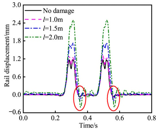
Figure 12.
Vertical rail displacements in time domain with an HMD of 2 mm.
The maximum vertical displacements of rail and slab and the corresponding change rates with different LMDs and HMDs are presented in Figure 13. Overall, the changes of rail displacements due to mortar disengagement are obviously smaller than that of slab. Under the same mortar disengagement condition, the change rate of slab displacement is approximately twice that of rail displacement. The main reason is that the mortar disengagement directly leads to insufficient support at the bottom of slab. However, fasteners connecting the rail and slab weaken the force transmitted from slab and the effect of mortar disengagement on the rail is reduced.
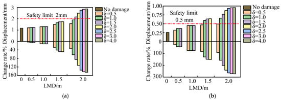
Figure 13.
The maxima and change rates of track structure displacements with different LMDs and HMDs: (a) Rail displacements; (b) Slab displacements.
As shown in Figure 13a, the maximum rail displacements are hardly affected by mortar disengagement when LMD is no more than 1 m. When LMD reaches 2 m, the maximum rail displacements increase sharply with the increase of HMD and exceed the critical value of 2 mm with HMD of 1 mm. With the deterioration of mortar disengagement, the maximum rail displacements are increased from 1.18 mm to 2.87 mm, and nearly achieve an increase of 145%. As seen in Figure 13b, the maximum slab displacements increase significantly as soon as the mortar layer is separated from the slab. The growth rate of the slab displacement amplitude is as high as 272% with an LMD of 2 m and HMD of 4 mm. When LMD reaches 1.5 m, the maximum slab displacement increases significantly and is about to exceed the safety limit of 0.5 mm.
3.2.2. Stresses of the Slab and Mortar Layer
Figure 14 indicates the effects of LMD and HMD on the longitudinal tensile stress of slab and the vertical compressive stress of mortar layer. The maximum longitudinal tensile stress of the slab is obtained in Zone P and the maximum vertical compressive stress of mortar layer is obtained in Zone Q, as displayed in Figure 8a. Firstly, with the increase of the LMD and HMD, both the longitudinal tensile stress of the slab and the vertical compressive stress of the mortar layer increase, especially when LMD is no less than 1.5 m. When LMD is 2 m and the HMD is between 0–3 mm, as well as when the LMD is 1.5 m and HMD is between 0–1.5 mm, the growth rates of the longitudinal tensile stress of slab and the vertical compressive stress of the mortar layer are relatively fast. It is highly possible that the mortar disengagement at this stage will cause further damage to the slab and mortar layer. The longitudinal tensile stress of slab is up to 3.24 MPa with LMD of 2 m and HMD of 3 mm, which is 2.9 times than that without mortar disengagement. Although the longitudinal tensile stress of slab does not reach the safety limit of 3.5 MPa, it is likely to cause transverse penetration cracks on the slab surface, which is detrimental to the carrying capacity and the durability of the slab.
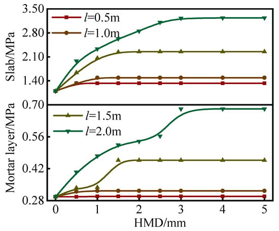
Figure 14.
Longitudinal tensile stress of slab and vertical compressive stress of mortar layer under different mortar disengagement conditions.
According to the ‘Provisional Technical Conditions for the CA Mortar of CRTSII Ballastless Slab Track’, the compressive strength of CA mortar shall not be less than 15 MPa as its elastic modulus is between 7000–10,000 MPa. As displayed in Figure 14, the vertical compressive stress of mortar layer is far below the specified safety limit. Although the vertical compressive stress of the mortar layer with different mortar disengagement do not exceed the safety limit, the development of fatigue damage to mortar layer would be accelerated under the repeated high-frequency train loads.
4. Conclusions
The mortar disengagement leading to insufficient support under the slab affects the track dynamic irregularity and further adversely influences the responses of the wheel–rail system. To study the influence of mortar disengagement with different lengths and heights on the vibration performances of vehicle and track structures, a rigid vehicle–flexible track coupled dynamics simulation model with mortar disengagement is developed in SIMPACK platform with the help of ANSYS software. The conclusions are drawn as follows:
- (1)
- The dynamic performances of vehicle and track systems are affected by LMD more evidently than HMD. When LMD is no more than 1 m, the dynamic performances of vehicle and track systems are hardly influenced by mortar disengagement with the maximum increase rate less than 10% except for the slab displacement. When LMD reaches 1.5 m, mortar disengagement becomes the dominant factor in aggravating the dynamic vibrations of vehicle and track systems.
- (2)
- The vertical wheel–rail contact force and the rail displacement exceed the safety limit of 170 kN and 2 mm with the LMD of 2 m and HMD of 1.5 mm. The vertical slab displacement and the longitudinal tension stress of the slab are most significantly affected, with increase rates of 190% and 272%, respectively. When LMD reaches 1.5 m, the maximum slab displacement exceeds the safety limit of 0.5 mm.
- (3)
- When LMD is 0.5 m, 1 m, 1.5 m and 2 m, and the corresponding HMD is 1 mm, 1.5 mm, 2 mm and 4 mm, respectively, the mortar disengagement develops into a mortar void. At this stage, the mortar layer no longer supports the slab even if the vehicle passes through the damaged zone.
This study provides a reference for formulating the repairing plan of mortar disengagement, which is conductive to relieving the pressure of track maintenance while ensuring the service life of track structures and the operation safety and riding comfort of the vehicle. Specifically, it is recommended the repairing plan of mortar disengagement shall be delayed to reduce the workload of track maintenance when LMD is less than 1 m. When LMD is greater than 1.5 m, the mortar damage needs to be repaired immediately to ensure the service performance of the vehicle and track systems.
Author Contributions
Conceptualization, X.X. and Z.R.; methodology, X.X.; software, X.X.; validation, X.X. and Z.R.; formal analysis, X.X. and Z.R.; investigation, X.X.; resources, X.X.; data curation, X.X.; writing—original draft preparation, X.X.; writing—review and editing, X.X.; visualization, X.X.; supervision, X.X. and Z.R.; project administration, Z.R.; funding acquisition, Z.R. All authors have read and agreed to the published version of the manuscript.
Funding
This work is supported by the National Natural Science Foundation of China, grant number 11790281.
Conflicts of Interest
The authors declare no conflict of interests.
Appendix A

Table A1.
Parameters of the vehicle model.
Table A1.
Parameters of the vehicle model.
| Structure | Parameters | Value |
|---|---|---|
| Car body | Mass/(kg) | 33,766 |
| Inertial of longitudinal motion/(kg/m2) | 109,400 | |
| Inertial of transverse motion/(kg/m2) | 128,400 | |
| Inertial of vertical motion/(kg/m2) | 1,561,300 | |
| Bogie | Mass/(kg) | 2400 |
| Inertial of longitudinal motion/(kg/m2) | 1944 | |
| Inertial of transverse motion/(kg/m2) | 1314 | |
| Inertial of vertical motion/(kg/m2) | 2400 | |
| Wheelset | Mass/(kg) | 1517 |
| Inertial of longitudinal motion/(kg/m2) | 693 | |
| Inertial of transverse motion/(kg/m2) | 118 | |
| Inertial of vertical motion/(kg/m2) | 693 | |
| Primary suspension | Vertical stiffness/(MN/m) | 1.18 |
| Vertical damping/(kN.s/m) | 10 | |
| Secondary suspension | Vertical stiffness/(MN/m) | 0.19 |
| Vertical damping/(kN.s/m) | 120 | |
| Dimension | Distance between the bogie centers/(m) | 8.75 |
| Bogie wheelbase/(m) | 2.5 | |
| Radius of the wheel/(m) | 0.43 |

Table A2.
Parameters of the track model.
Table A2.
Parameters of the track model.
| Structure | Parameters | Value |
|---|---|---|
| Rail | Modulus of elasticity/(N/m2) | 2.1 × 10¹¹ |
| Density/(kg/m3) | 7850 | |
| Poisson’s ratio | 0.3 | |
| Rail mass per unit length/(kg) | 60 | |
| Fastener | Transverse stiffness/(MN/m) | 30 |
| Vertical stiffness/(MN/m) | 25 | |
| Transverse damping/(kN.s/m) | 25 | |
| Vertical damping/(kN.s/m) | 36 | |
| Spacing/(m) | 0.65 | |
| Slab | Structure parameters/(m) | 6.45 × 2.4 × 0.2 |
| Modulus of elasticity/(MN/m2) | 3.9 × 10⁴ | |
| Density/(kg/m3) | 2500 | |
| Poisson’s ratio | 0.3 | |
| CA mortar | Modulus of elasticity/(MN/m2) | 7000 |
| Density/(kg/m3) | 2590 | |
| Section depth/(m) | 0.03 | |
| Poisson’s ratio | 0.2 | |
| Base | Modulus of elasticity/(MN/m2) | 3.5 × 10⁴ |
| Density/(kg/m3) | 2500 | |
| Poisson’s ratio | 0.2 | |
| Subgrade | Equivalent stiffness/(MN/m3) | 76 |
| Equivalent damping/(N.s/m3) | 1.0 × 10⁵ |
References
- Xu, L.; Zhai, W. A three-dimensional dynamic model for train-track interactions. Appl. Math. Model. 2019, 76, 443–465. [Google Scholar] [CrossRef]
- Xu, P.; Cai, C. Dynamic analysis of longitudinally connected ballastless track on earth subgrade. J. Southwest Jiaotong Univ. 2011, 46, 189–194. (In Chinese) [Google Scholar] [CrossRef]
- Zeng, X.; Xie, Y.; Deng, D. Conductivity behavior of the fresh CA mortar and its relationship with the fluidity properties. Constr. Build. Mater. 2012, 36, 890–894. [Google Scholar] [CrossRef]
- Qiu, K.; Chen, H.; Ye, H.; Hong, J.; Sun, W.; Jiang, J. Thermo-mechanical coupling effect on fatigue behavior of cement asphalt mortar. Int. J. Fatigue 2013, 51, 116–120. [Google Scholar] [CrossRef]
- Shan, Y.; Zheng, S.; Zhang, X.; Luo, W.; Mao, J.; Kong, D. Fatigue performance of the CA mortar used in CRTS I ballastless slab track under simulated servicing condition. Materials 2018, 11, 2259. [Google Scholar] [CrossRef] [Green Version]
- Wang, P.; Xu, H.; Chen, R. Effect of cement asphalt mortar debonding on dynamic properties of CRTS II slab ballastless track. Adv. Mater. Sci. Eng. 2014, 2014, 193128. [Google Scholar] [CrossRef] [Green Version]
- Coussy, O.; Dangla, P.; Lassabatere, T.; Baroghel-Bouny, V.J.M. Structures, The equivalent pore pressure and the swelling and shrinkage of cement-based materials. Mater. Struct. 2004, 37, 15–20. [Google Scholar] [CrossRef]
- Ren, J.; Wang, J.; Li, X.; Wei, K.; Li, H.; Deng, S. Influence of cement asphalt mortar debonding on the damage distribution and mechanical responses of CRTS I prefabricated slab. Constr. Build. Mater. 2020, 230, 116995. [Google Scholar] [CrossRef]
- Steenbergen, M.J.M.M.; Metrikine, A.V.; Esveld, C. Assessment of design parameters of a slab track railway system from a dynamic viewpoint. J. Sound Vib. 2007, 306, 361–371. [Google Scholar] [CrossRef]
- Zhou, L.; Yang, L.; Shan, Z.; Peng, X.; Mahunon, A.D. Investigation of the fatigue behaviour of a ballastless slab track–bridge structural system under train load. Appl. Sci. 2019, 9, 3625. [Google Scholar] [CrossRef] [Green Version]
- Zhou, L.; Wei, T.; Zhang, G.; Zhang, Y.; Akim Djibril Gildas, M.; Zhao, L.; Guo, W. Experimental study of the influence of extremely repeated thermal loading on a ballastless slab track-bridge structure. Appl. Sci. 2020, 10, 461. [Google Scholar] [CrossRef] [Green Version]
- Su, C.; Liu, D.; Ding, C.; Gong, C.; Zhao, P. Liu, X. Experimental Study on Bond Performances of Track Slab and Mortar Based on DIC Technology. KSCE J. Civ. Eng. 2018, 22, 3546–3555. [Google Scholar] [CrossRef]
- Ren, J.; Li, H.; Cai, X.; Deng, S.; Wang, J.; Du, W. Viscoelastic deformation behavior of cement and emulsified asphalt mortar in China railway track system I prefabricated slab track. J. Zhejiang Univ.-SCIENCE A 2020, 21, 304–316. [Google Scholar] [CrossRef]
- Zhu, S.; Fu, Q.; Cai, C.; Spanos, P.D. Damage evolution and dynamic response of cement asphalt mortar layer of slab track under vehicle dynamic load. Sci. China Technol. Sci. 2014, 57, 1883–1894. [Google Scholar] [CrossRef]
- Ren, J.; Ye, W.; Deng, S.; Du, W.; Zhang, K. Influence of the strain rate on the dynamic damage of cement-asphalt mortar in prefabricated slab tracks. Constr. Build. Mater. 2021, 299, 123944. [Google Scholar] [CrossRef]
- Liu, D.; Liu, Y.; Ren, J.; Yang, R.; Liu, X. Contact loss beneath track slab caused by deteriorated cement emulsified asphalt mortar: Dynamic characteristics of vehicle-slab track system and prototype experiment. Math. Probl. Eng. 2016, 2016, 3073784. [Google Scholar] [CrossRef]
- Li, X.; Ren, J.; Liu, X. Dynamic influence of gap height of CA mortar on track structure under mixed traffic conditions. J. Southwest Jiaotong Univ. 2018, 53, 958–965. (In Chinese) [Google Scholar] [CrossRef]
- Li, P.; Liu, X.; Li, G. Influence of CA mortar void on dynamic characteristics of unit slab track on bridge. China Railw. Sci. 2014, 35, 20–27. (In Chinese) [Google Scholar] [CrossRef]
- Yang, J.; Liu, X.; Liu, Y. Influence of seam in type I slab ends on dynamic characteristics of track and vehicle. J. Southwest Jiaotong Univ. 2014, 49, 432–437. (In Chinese) [Google Scholar] [CrossRef]
- Mao, J.; Zhang, J.; Feng, Q.; Cao, H. Influence of emulsified cement asphalt mortar seam on dynamic characteristics of vehicle- china railway track system ii ballastless track system. J. Eng. Sci. Technol. Rev. 2017, 10, 52–61. [Google Scholar] [CrossRef]
- Zhao, G.; Gao, L.; Zhao, L.; Zhou, Y. Analysis of dynamic effect of gap under CRTS II track slab and operation evaluation. J. China Railw. Soc. 2017, 39, 35–41. (In Chinese) [Google Scholar] [CrossRef]
- Yang, R.; Liu, K.; Ren, J. Research on effect of cement asphalt mortar damages on dynamic characteristics of wheel-rail system. J. China Railw. Soc. 2014, 36, 79–84. (In Chinese) [Google Scholar] [CrossRef]
- Liu, D.; Su, C.; Zhang, S. Experimental study on influence of contact loss beneath track slab end on dynamic characteristics of CRTSIslab track. J. China Railw. Soc. 2017, 39, 99–104. (In Chinese) [Google Scholar] [CrossRef]
- Ren, J.; Li, X.; Yang, R.; Wang, P.; Xie, P. Criteria for repairing damages of CA mortar for prefabricated framework-type slab track. Constr. Build. Mater. 2016, 110, 300–311. [Google Scholar] [CrossRef]
- Sysyn, M.; Przybylowicz, M.; Nabochenko, O.; Liu, J. Mechanism of Sleeper–Ballast Dynamic Impact and Residual Settlements Accumulation in Zones with Unsupported Sleepers. Sustainability 2021, 13, 7740. [Google Scholar] [CrossRef]
- Sysyn, M.; Przybylowicz, M.; Nabochenko, O.; Kou, L. Identification of Sleeper Support Conditions Using Mechanical Model Supported Data-Driven Approach. Sensors 2021, 21, 3609. [Google Scholar] [CrossRef]
- Liu, K. Research on Cement Asphalt Mortar Damage and Maintenance Standards for Frame Type of Slab Track; Southwest Jiaotong University: Chengdu, China, 2013. (In Chinese) [Google Scholar]
- Luo, J.; Zhu, S.; Zhai, W. An efficient model for vehicle-slab track coupled dynamic analysis considering multiple slab cracks. Constr. Build. Mater. 2019, 215, 557–568. [Google Scholar] [CrossRef]
- Cai, C.; He, Q.; Zhu, S.; Zhai, W.; Wang, M. Dynamic interaction of suspension-type monorail vehicle and bridge: Numerical simulation and experiment. Mech. Syst. Signal Processing 2019, 118, 388–407. [Google Scholar] [CrossRef]
- Zhai, W.; Cai, C. Train/track/bridge dynamic interactions: Simulation and applications. Veh. Syst. Dyn. 2002, 37 (Suppl. 1), 653–665. [Google Scholar] [CrossRef]
- Neves, S.G.M.; Azevedo, A.F.M.; Calçada, R. A direct method for analyzing the vertical vehicle–structure interaction. Eng. Struct. 2012, 34, 414–420. [Google Scholar] [CrossRef] [Green Version]
- Blanco-Lorenzo, J.; Santamaria, J.; Vadillo, E.G.; Oyarzabal, O. Dynamic comparison of different types of slab track and ballasted track using a flexible track model. Proc. Inst. Mech. Eng. Part F: J. Rail Rapid Transit. 2011, 225, 574–592. [Google Scholar] [CrossRef]
- Zhu, S.; Cai, C.; ZHai, W. Interface Damage Assessment of Railway Slab Track Based on Reliability Techniques and Vehicle-Track Interactions. J. Transp. Eng. 2016, 142, 04016041. [Google Scholar] [CrossRef]
- Panayirci, H.M.; Pradlwarter, H.J.; Schuëller, G.I. Efficient stochastic structural analysis using Guyan reduction. Adv. Eng. Softw. 2011, 42, 187–196. [Google Scholar] [CrossRef]
- Guyan, R.J. Reduction of stiffness and mass matrices. AIAA J. 1965, 3, 380. [Google Scholar] [CrossRef]
- Ren, Z.; Xin, X.; Sun, G.; Wei, X. The effect of gear meshing on the high-speed vehicle dynamics. Veh. Syst. Dyn. 2020, 59, 743–764. [Google Scholar] [CrossRef]
- Wang, S.; Zhao, W.; Zhang, G.; Li, F.; Du, Y. Fourier Series Approach for the Vibration of Euler–Bernoulli Beam under Moving Distributed Force: Application to Train Gust. Shock Vib. 2019, 2019, 2542349. [Google Scholar] [CrossRef]
- Wu, X.; Rakheja, S.; Ahmed, A.K.W.; Chi, M. Influence of a flexible wheelset on the dynamic responses of a high–speed railway car due to a wheel flat. Proc. Inst. Mech. Eng. Part F: J. Rail Rapid Transit 2017, 232, 1033–1048. [Google Scholar] [CrossRef]
- Yang, G. Research on the Dynamic Performance of High-Speed Wheel/Rail System Considered Elastic and Ratation of Wheelset; Beijing Jiaotong University: Beijing, China, 2017. (In Chinese) [Google Scholar]
- Kuo, C.; Huang, C.; Chen, Y. Vibration characteristics of floating slab track. J. Sound Vib. 2008, 317, 1017–1034. [Google Scholar] [CrossRef]
- Zhai, W.; Liu, P.; Lin, J.; Wang, K. Experimental investigation on vibration behaviour of a CRH train at speed of 350 km/h. Int. J. Rail Transp. 2015, 3, 1–16. [Google Scholar] [CrossRef]
- Xue, R.; Ren, Z.; Fan, T.; Rakheja, S. Vertical vibration analysis of a coupled vehicle-container model of a high-speed freight EMU. Veh. Syst. Dyn. 2020, 60, 1–25. [Google Scholar] [CrossRef]
- Nan, H. Analysis on the Dynamic Characteristics of CRTS II Type Slab Ballastless Track on Subgrade and the Parametric Study; Lanzhou Jiaotong University: Lanzhou, China, 2012. (In Chinese) [Google Scholar]
- Zhang, S. The Beijing-Tianjin Inter-City High-Speed Railway System Debugging Techniques; China Railway Publishing House: Beijing, China, 2008. (In Chinese) [Google Scholar]
- Chen, L.; Chen, J.; Wang, J. Study on stress transfer and interface damage of CRTSIIslab ballastless track. J. China Railw. Soc. 2018, 40, 130–138. (In Chinese) [Google Scholar] [CrossRef]
- Zhang, G. Study of the Effect of Cement Asphalt Mortar Disease on Mechanical Properities of CRTSII Slab Ballastless Track; Central South University: ChangSha, China, 2013. (In Chinese) [Google Scholar]
Publisher’s Note: MDPI stays neutral with regard to jurisdictional claims in published maps and institutional affiliations. |
© 2022 by the authors. Licensee MDPI, Basel, Switzerland. This article is an open access article distributed under the terms and conditions of the Creative Commons Attribution (CC BY) license (https://creativecommons.org/licenses/by/4.0/).