1. Introduction
The use of robotics for aiding people in everyday life is becoming increasingly more common and assistive robotics is a promising aspect for individuals who would otherwise be dependent on a caregiver for daily activities [
1,
2]. This potential for assistive robots is especially high for individuals who are exceedingly dependent on caregivers in everyday life such as individuals with tetraplegia, i.e., partial or complete loss of control in both arms and legs. A typical cause of tetraplegia is SCI (spinal cord injury), and it is estimated that 250,000 to 500,000 people suffer from SCI every year [
3], with roughly one-third of these cases resulting in tetraplegia [
4].
The mean age of individuals with tetraplegia was reported to be 33 years old when sustaining the injury [
4], but especially males aged 20–29 years and females aged 15–19 years have seen spikes in the incident rate of traumatic spinal cord injuries [
3]. The motivation for focusing on tetraplegia is further supported by a high life expectancy after the injury, especially for young individuals [
3]. An individual with tetraplegia caused by SCI at the age of 25 years can often expect to live for another 40 years. One of the most important tools for individuals with tetraplegia is often a powered wheelchair, offering both mobility and independence [
3]. However, tasks requiring interaction with an object, such as drinking and eating, still require assistance from a caregiver. The frustration of not being able to perform these things independently becomes even greater for prolonged sessions, for instance, during recreational activities, such as watching a movie while enjoying a beverage or snacking [
5].
To mitigate the challenges above and increase the independence of individuals with tetraplegia, we propose the novel combination of using a tongue-based interface combined with computer vision in a semi-autonomous control scheme to enable individuals with tetraplegia to effectively control an upper limb exoskeleton, as shown in
Figure 1.
An upper limb exoskeleton is used, as several studies have successfully demonstrated how it can help restore some of the lost functionality for individuals with movement impairments in the arms [
6,
7]. Furthermore, the tongue-based interface has previously been shown to be an efficient and suitable interface for individuals with tetraplegia to control an exoskeleton [
8,
9]. Finally, a semi-autonomous control scheme assists the user in controlling the exoskeleton based on input from a computer vision module, which detects and analyzes nearby objects. This is performed as several studies suggest that such an approach can be beneficial for controlling assistive robotic manipulators [
10].
Hence, the main contributions of the paper are the following:
We design and implement an adaptive semi-autonomous control scheme based on computer vision and evaluate it in the context of controlling an upper limb exoskeleton through a tongue-based interface.
We evaluate the effectiveness and intuitiveness of various control schemes for performing semi-autonomous tongue-control of an upper limb exoskeleton, through studies including both participants with and without tetraplegia.
2. Related Work
The proposed system consists of an upper limb exoskeleton as it would enable individuals with tetraplegia to regain some of the lost functionality in their arms. The idea of upper limb exoskeletons for users with movement impairments have, in several previous studies, been shown to be useful for both assistive purposes [
6,
11] and for rehabilitation [
7,
12,
13].
However, a challenging aspect of using an exoskeleton for people with tetraplegia is how to interface with it. A common approach for controlling upper limb exoskeletons is with EMG (electromyography) [
7,
14] to detect muscle activity, which is not feasible in case of severe tetraplegia. Other approaches require the user to control the exoskeleton using a joystick, operated by a single finger [
6], which is not possible for complete functional tetraplegia either. Others have explored the idea of using eye movements [
13] or voice commands [
6] to allow individuals with movement impairments to interface with an upper limb exoskeleton. Eye movements or voice commands are plausible options but can be very tedious to use in the long run and are easily susceptible to noise such as accidental eye movements or nearby sounds. In one study, the majority of the participants preferred other options over the voice-based control [
6]. Another possibility is BCI-based control (brain–computer interface), where signals are measured from the brain of the user controlling the upper limb exoskeleton [
12]. However, weak points of a BCI-based interface is the low signal-to-noise ratio, the need for substantial calibration, and the low throughput, both in terms of the number of different commands and also how fast one can issue them. This often restricts the use of BCI-based interfaces to rely on predefined movements which are completely automated [
15], forcing the user to relinquish control completely for periods of time.
A tongue-based interface does not suffer from many of the issues highlighted above. It offers high throughput, both in terms of the number of possible commands and also in terms of how fast they can be issued [
16]. Furthermore, several studies have demonstrated that a tongue-based interface can be used by individuals with tetraplegia to control various assistive devices, such as an upper limb exoskeleton [
8] or a robotic arm [
17]. These considerations have led to the choice of a tongue-based interface.
A semi-autonomous control scheme, where parts of the control are automated using computer vision, is included in the system to further enhance the tongue-based control of the exoskeleton. Several studies have reported increased performance when employing computer vision for semi-autonomous control of assistive robotic manipulators [
10], such as completing tasks faster [
18,
19] or being more precise in the movement of the manipulator [
20,
21]. Furthermore, there are several examples of computer vision either improving the fine control of an upper limb exoskeleton [
13,
21] or automating entire parts of a task [
11,
22,
23] for users with paralysis.
Many of the approaches relying on computer vision employ a clear-cut strategy for arbitrating control between the user and the system, where certain parts of the process are completely automated [
10]. For example, reaching for and grasping an object once the user triggers this predefined task, either from a tongue-based interface [
20], through voice commands [
18], or through eye movements [
11,
22]. The user would, in these cases, relinquish complete control until the task is completed, i.e., the object is reached and grasped. This fixed level of autonomy, where the automated process is clearly defined, is likely common because it is easy to implement, easy to understand for the user, and it improves performance in many cases. Sometimes it is also the only option due to the limitations of the interface used for the control [
11,
22].
However, using a fixed level of autonomy introduces the problem of finding an optimal balance in the arbitrating control between the user and the system [
10]. If the user is primarily in control at all times, without any automating, it defeats the purpose of having semi-autonomous control in the first place. On the other hand, a high level of autonomy where nearly everything is automated may not be a satisfying experience for the user either [
24]. Automating may even counteract what the user is trying to achieve in cases where the automating performs the wrong action, e.g., reaching for the wrong object, and it may impose a safety risk. Even cases where the automating acts as intended may result in lower satisfaction for the user as they may no longer feel in control, especially for individuals with movement impairments [
19].
One way to avoid or minimize many of these issues is to rely on an adaptive level of autonomy instead of a fixed one. Several studies on teleportation of robots have successfully demonstrated semi-autonomous control with an adaptive level of autonomy based on a confidence-measure [
25,
26]. This confidence-measure is an expression of how certain the system is in its own prediction of the intent of the user, such as interacting with a certain object. The system will hence offer a lot of assistance in scenarios where it has a high confidence of being able to correctly assist the user. The opposite is also true; the system will offer no or little assistance in cases of low confidence where it is unclear what the user is trying to accomplish. A benefit is hence that it can adapt its level of autonomy to fit different scenarios.
Hence, in the current study, three different control schemes were implemented: a non-autonomous (i.e., manual) control, a semi-autonomous control with a fixed level of autonomy, and a semi-autonomous control using a confidence-based adaptive level of autonomy. The implementation of each is described in further detail in
Section 3.4. These three different control schemes are evaluated and compared against each other, as described in
Section 4. The purpose is to determine whether using computer vision for tongue-based control of an upper limb exoskeleton is beneficial or not and whether semi-autonomous control with a fixed or adaptive level of autonomy is preferable in this context.
3. Method
The following describes the different main components of the proposed system, as also shown in
Figure 1. The upper limb exoskeleton is controlled by mixing input from the user and from the computer vision module. The user provides input to the system through a tongue-based interface as the exoskeleton is designed for individuals with tetraplegia. The computer vision module is designed to detect objects in front of the user and infer how to grasp them. The computer vision module is also designed to predict the intention of the user, i.e., what object to grasp, to assist the user in controlling the exoskeleton. Finally, the control scheme module combines input from the user and the computer vision module to actuate the exoskeleton.
3.1. Upper Limb Exoskeleton
The exoskeleton used in this study is the EXOTIC upper limb exoskeleton, as shown in
Figure 2a. It has four degrees of freedom (DoFs): two in the shoulder, one in the elbow, and one in the wrist. The number of DoFs is kept at a minimum to reduce the bulkiness of the exoskeleton. The DoFs included have been carefully selected to support tasks such as picking up objects from a table and bringing them to the mouth of the user. The number of DoFs in the exoskeleton also means that it must use three of its four DoFs to reach an arbitrary position, leaving only rotation around the wrist as the free DoF for altering the orientation of the end effector, i.e., the hand. A more thorough description of the upper limb exoskeleton and its capabilities can be found in [
27,
28].
For the end effector, a Carbonhand from Bioservo Technologies AB is used and provides active actuation when closing the hand of the user. Only the thumb, middle finger, and ring finger are actuated in the Carbonhand. Opening of the hand is passive and is performed using an elastic fabric on the back of the hand.
3.2. Tongue-Based Interface
The proposed system makes use of an inductive intra-oral tongue interface (ITCI) [
9,
29], as shown in
Figure 2b. The ITCI sits in the roof of the user’s mouth and is held in place similar to a dental brace. The unit contains a small battery and can hence operate wirelessly while sitting in the mouth of the user. The entire area of the ITCI is covered by 18 small inductive sensors which can be activated using a tongue piercing made of metal. The tongue piercing and dental braces are for long-term usage and not for temporary usage. In the studies, surgical glue was used to attach a small piercing-like metal cylinder on the tongue of the participants instead. The ITCI was held in place in the roof of the participant’s mouth using dental putty instead of a custom dental brace.
The inductive sensors of the ITCI were mapped to the layout shown in
Figure 2c to control the upper limb exoskeleton [
28]. The upper part of the ITCI functions as a joystick where the user can control the forward (F), backward (B), left (L), and right (R) motion of the exoskeleton. A slider is used to control the exoskeleton either down or up and is placed right below the joystick-like control. All these movements happen in relation to the current position of the end-effector, i.e., the hand of the user. The lower part of the ITCI contains controls for opening and closing the Carbonhand along with a slider for controlling the wrist rotation of the exoskeleton. Finally, an “auto grasp” button is located slightly below the middle of the ITCI layout. When pressed, the button will activate the fixed semi-autonomous control of the exoskeleton which is described in more detail later in
Section 3.4. The exact same layout is used for both the manual control and the adaptive semi-autonomous control. The only exception is that the auto grasp button does nothing while using these two control schemes.
The layout of the ITCI, along with the current location of the tongue piercing in the mouth, is shown to the user only when training to use the tongue interface. All the results presented later are hence gathered without any visual feedback from the tongue interface. This is performed as the main idea of the system is to be able to use it without any visual feedback besides the actual movement of the exoskeleton.
3.3. Computer Vision Module
The computer vision part of the system is mainly responsible for performing object detection, intent prediction, and grasp detection, as outlined in
Figure 3. The input for the computer vision module is a small RGB-D camera (Intel RealSense D415), providing both color and depth information, mounted at the shoulder joint of the exoskeleton (see
Figure 2a) and pointing towards the area in front of the user. This specific camera was chosen for its small baseline, i.e., the distance between the two sensors used for depth measurements, making it suitable for capturing depth data at close range (minimum operating range ≈30 cm). The small baseline also results in a small camera footprint, making it easier to mount on the exoskeleton discreetly and without the camera getting in the way. The depth information from the camera is not used during object detection but it is used for both the intent prediction and grasp detection, as described later.
3.3.1. Object Detection
An important part of the computer vision module is to be able to detect any objects of interest in front of the user that the exoskeleton might be able to reach. The current state-of-the-art approaches for object detection are often based on deep learning [
30,
31], where neural networks are trained on huge amounts of labeled data [
32]. These huge amounts of training data are required for the deep learning-based object detectors to learn a wide range of different objects and to generalize well to different environments. However, performing object detection in this way adds another layer of complexity, and thereby uncertainty, on top of an already complex system.
Instead, a classic approach of relying on color for segmentation of the objects is used, where thresholding is applied to the HSV (hue, saturation, value) color space, such that all bright red objects in the RGB image from the camera are detected. This approach is characterized by producing stable object detections in a controlled environment for a few objects, which is what is needed for the experiment. The decision to use this classic approach based on colors for object detection is hence an attempt at minimizing any uncertainty during the experiment related to object detection. This decision was deemed acceptable as the focus is not the computer vision part but rather on testing the different control schemes.
3.3.2. Intent Prediction
Once any objects are detected, the system must predict the intent of the user. The intent prediction is based on the direction of the user’s palm, the intuition being that people generally have their palm pointed towards an object when grasping it. Using this assumption also had the benefit of making it easy to explain how the system works to the users of the exoskeleton.
The intent prediction works by projecting a ray from the palm of the user, as depicted in
Figure 4. The orthogonal Euclidean distance between this ray
and any object in the scene is then calculated and the object resulting in the shortest distance is then considered the predicted intention of the user, i.e., object
A. Additionally, only objects facing the palm of the user’s hand are considered during the intent prediction and any objects facing the back of the hand are ignored, such as object
C.
An alternative to this ray-based method could have been an approach based purely on distance [
26], i.e., finding the nearest object. The obvious drawback of such an approach is that it would only consider the nearest object, i.e.,
B, and disregard all other objects in the scene. Furthermore, using solely the shortest distance may also cause the intent prediction to gravitate towards the nearest object to the point where it might become difficult for the user to break away from that object. This effect is less pronounced with the ray-based method as only slight adjustments of the exoskeleton are required to point it towards the intended target. Finally, the ray-based approach for intent prediction was found to be quite stable when moving towards an object. This behavior avoids problematic scenarios where the system might suddenly change the predicted intention while moving towards an object; something that could easily occur if using a nearest object approach for the intention prediction.
3.3.3. Grasp Detection
The last part of the computer vision pipeline detects how to grasp the target object, i.e., the object that the user is interested in interacting with. The experimental setup included two objects for the user to interact with: a strawberry and a bottle. A simple rule-based strategy relying on fitting cylinders [
23] was hence used for the grasp detection. First, the detection from earlier (
Section 3.3.1) was used to mask the depth information from the RGB-D camera such that the result was a point cloud of the target object, as shown in
Figure 3. An RANSAC-based algorithm [
33] was then used to fit a cylinder to the masked point cloud [
34], resulting in both the position and orientation of the object (the central axis of the cylinder) along with its approximate size (the cylinder diameter and height).
The fitted cylinders were then converted into a grasp pose for the exoskeleton, as illustrated in
Figure 5, which depicts how the coordinate frame of end-effector, i.e., the Carbonhand, should be positioned and oriented in order to grasp the two objects on the table. The frame of the end-effector is placed in the palm of the Carbonhand and oriented such that the
z-axis is pointing out from the palm, the
y-axis points upwards, and the
x-axis points towards the thumb of the Carbonhand.
A rule-based approach is used for grasping the objects such that:
Position—The coordinate frame of the end-effector should be positioned halfway along the height of the cylinder, such that the object is grasped in the middle for stability. Furthermore, the position for grasping the object should be on the outer perimeter of the cylinder to avoid pushing the object away. An offset, equal to the radius of the detected cylinder, is applied in the direction towards the end-effector to avoid this.
Orientation—The coordinate frame of the end-effector should be oriented such that the y-axis is parallel with the axis of the cylinder, while also pointing upwards to avoid infeasible grasping orientations (such as trying to grasp the object with the palm of the hand facing away from the person in the exoskeleton). Furthermore, the z-axis should be orthogonal to the axis of the cylinder to avoid grasping the object at a skewed angle.
Furthermore, smaller objects (height less than ≈3 cm) are difficult to grasp using an upright orientation (such as the orientation of the Carbonhand depicted in
Figure 5). This is partly due to the design of the Carbonhand, where only the thumb, middle finger, and ring finger are actuated. An additional check is therefore implemented in the grasp detection, such that all objects fewer than 3 cm in height will be approached as a cylinder laying flat on the table, as also illustrated for the small strawberry in
Figure 5. Finally, it should be noted that a cylinder is a poor fit for a strawberry. Nevertheless, the above approach was found to produce an acceptable grasp for both the bottle and the strawberry.
3.4. Control Schemes
The purpose of the control schemes is to arbitrate input from the user, received through the ITCI, with the information from the computer vision module, i.e., what object to grasp and how to grasp it, in order to actuate the upper limb exoskeleton. Parts of the control of the exoskeleton will hence be automated, which is why some of the control schemes are referred to as semi-autonomous control.
Three different control schemes are implemented and tested against each other:
Non-Autonomous Control —The system offers no assistance at any point and the input from the computer vision module is ignored. The exoskeleton is manually controlled by the user at all times.
Fixed Semi-Autonomous Control—A fixed level of autonomy is used where the system will take over control of the exoskeleton when the user presses and holds the “auto grasp” button in the ITCI layout (
Figure 2c). While doing so, input from the computer vision module guides the hand of the exoskeleton towards the most likely object to grasp.
Adaptive Semi-Autonomous Control—The system will at all times assist the user in controlling the exoskeleton. The level of autonomy is adapted based on a confidence measure related to the certainty of the intent prediction from the computer vision module. A high certainty of the predicted intention being correct will result in a high confidence and the system will provide more assistance. In low-confidence scenarios, the opposite is true, and the system will provide little to no assistance. If the user does not activate the tongue interface the system does not move. The “auto grasp” button does nothing in this control scheme.
3.4.1. Fixed Semi-Autonomous Control
The fixed scheme for the semi-autonomous control switches from manual to automatic control as long as the user presses and holds the “auto grasp” button on the ITCI layout, as shown earlier in
Figure 2c. Having to press and hold the button instead of only pressing the button once is a safety measure as it provides an intuitive and easy way to stop the automatic control of the exoskeleton by simply letting go of that button. It also reduces the impact of random noise activating the “auto grasp” button or the user activating it by mistake. Both scenarios can easily occur, especially when learning to use the ITCI.
Once the automatic control is activated, the exoskeleton will move towards the target object as detected by the computer vision module. The exoskeleton will move the hand towards the detected grasp pose linearly while controlling both the position and orientation. While using the automatic control, the exoskeleton will avoid collisions with the table as an added safety measure. The actuation of the hand open/close of the Carbonhand is not part of the automatic control and will have to be activated manually by the user.
3.4.2. Adaptive Semi-Autonomous Control
The adaptive scheme for the semi-autonomous control relies on continuously blending input from the user and input from the computer vision module based on a confidence measure. This confidence measure is based on calculating the similarity of the command received from the user with the intention predicted by the computer vision module.
All commands from the user for manually moving the exoskeleton (up, right, forward, and so on) can be described in 3D using the vector
. As only the direction of the user input is considered for calculating the confidence, the normalized vector,
, is used. A similar vector can be formulated for the computer vision module,
, which describes how the position of the exoskeleton’s end-effector should change in order to reach the grasp pose for the predicted target. The direction of this vector from the computer vision module is expressed as the normalized vector,
. The confidence is then measured using the scalar product between these two normalized direction vectors:
The addition and division of the scalar product between the two direction vectors serves to normalize the resulting scalar to a value between 0 and 1. A high confidence indicates that the user and the computer vision want to move in the same direction and vice versa. A confidence measure of or below corresponds to an angle of 90o or more between the direction from the user input, , and the direction from the computer vision module, .
The adaptive semi-autonomous control relies on the above confidence measure to arbitrate the control of the exoskeleton between the user and the computer vision module. This arbitration is performed using a linear blending [
26] between the input from the user and the input from the computer vision module:
where
is the arbitration factor controlling the blending, such that the user is completely in control of the exoskeleton when
, and vice versa.
is the output used to actuate the exoskeleton in terms of a linear velocity
and an angular velocity
for the wrist rotation. Only the angular movement around the wrist is considered in the above blending because the user is limited to wrist rotation only, as explained earlier in
Section 3.1. Lastly,
,
, and
are velocity vectors and hence not normalized.
Finally, the arbitration factor
for the adaptive semi-autonomous control is dependent on the confidence measure
, as shown in
Figure 6. The main property of the selected arbitration curve was to ensure that the confidence reached an acceptable level before providing any assistance. No assistance is provided at all until the confidence measure
, which corresponds to an angular difference of less than
between the direction vectors from the user and the computer vision module.
The selected arbitration curve is inspired by another study [
26] that tested a very aggressive arbitration curve with a sudden jump in the arbitration factor against a more timid one with a gradual change. Their results indicated that the aggressive one worked well in scenarios where the task was difficult and the intent prediction was correct. However, for all other scenarios the timid arbitration curve was to be preferred in terms of task completion time and user preference. The arbitration curve for the adaptive semi-autonomous control was hence designed to be more timid with a gradual change in the arbitration factor.
The behavior of the two other control schemes can also be illustrated using an arbitration curve, as also shown in
Figure 6. For the non-autonomous control, the user is always in full control and the computer vision provides no assistance. The arbitration factor is hence fixed at
, i.e., the human is in control, no matter what the confidence of the system is for this control scheme. The arbitration curve for the fixed semi-autonomous control is also fixed at
with the exception of a sudden jump to
. This jump illustrates the behavior of the fixed semi-autonomous control which takes complete control of the exoskeleton while the user presses and holds the “auto grasp” button. The confidence measure for the fixed semi-autonomous control can hence also be viewed as a step function, where
when the user is pressing and holding the “auto grasp” button, and
otherwise.
4. Evaluations
To test the developed system, two studies were conducted; study A included 10 participants without tetraplegia and study B included 7 participants with tetraplegia. The overall structure of both studies is described in this section and the points where the two studies differ are described in more detail later.
The purpose of the study is to test the following hypotheses:
H1:The adaptive semi-autonomous control is better than the non-autonomous control.
H2:The fixed semi-autonomous control is better than the non-autonomous control.
H3:The adaptive semi-autonomous control is better than the fixed semi-autonomous control.
Whether a respective control scheme can be considered better than the others is assessed using different performance metrics and questionnaires, described later in
Section 4.2 and
Section 4.3.
4.1. Setup
An example of the setup using during both studies can be seen in
Figure 7a, where the participant is placed in a wheelchair while the exoskeleton is attached to their right arm. The length of each link in the exoskeleton was adjusted to fit the participant and the kinematic model of the exoskeleton was updated accordingly. Once the exoskeleton was attached, the participant was asked to complete a small calibration procedure to find the center point of their hand. This was necessary as the soft nature of the Carbonhand meant that the participant’s hand did not always end up in the same location. The calibration procedure consisted of grasping a bottle with a known position and orientation and was repeated each time the participant wore the exoskeleton.
The participant was seated at a table with a computer screen, the wireless receiver for the tongue-based interface, several ArUco markers, and the objects to interact with. The computer screen is used to provide visual feedback to the user during the experiment. The screen displayed visual feedback for the tongue-based interface while the user learned to control it during the first days of the study. When testing the control schemes, the screen is only used to display the current control scheme to the participant. The ArUco markers were added to make it possible to cross-reference recorded images and videos from multiple sources.
Finally, the objects on the table included either a plastic bottle or a plastic strawberry, as shown in
Figure 7b. Both objects are bright red to make detection easier. These two objects could be placed in two predefined positions, as illustrated by the markers under each object. The choice of using a strawberry and a bottle was to have a larger object which was easy to grasp and to have a smaller object which would be more difficult to grasp. Grasping the strawberry would, in most cases, require the participant to rotate the wrist of the exoskeleton. This was not necessary in the case of the bottle.
Four possible test scenarios were constructed from these two objects:
Bottle—Single: Only the bottle is present in one of the two predefined positions. The user must grasp and lift the bottle.
Strawberry—Single: Only the strawberry is present in one of the two predefined positions. The user must grasp and lift the strawberry.
Bottle—Multi: Both the bottle and the strawberry are present and placed in the two predefined positions. The user must grasp and lift the bottle.
Strawberry—Multi: Both the bottle and the strawberry are present and placed in the two predefined positions. The user must grasp and lift the strawberry.
The test scenarios were constructed to create both easy and difficult situations. In easy scenarios, with only a single object, the intention prediction would always be correct. In the more challenging scenarios, with two objects, the intent prediction could possibly be wrong, and the participant would also have to avoid collision with the object not to grasp. Furthermore, the test scenarios involving the strawberry are anticipated to be more difficult due to its smaller size and as it requires using the wrist rotation of the exoskeleton in order to grasp it. A video of a few trials from study A can be found in
Supplementary Materials.
Each trial started with the exoskeleton being in a predefined home position, as shown in
Figure 7a. The participant was then told what control scheme was active, and what object to grasp and lift; afterwards, they could start moving the exoskeleton. The start of each trial is marked by the participant starting to move the exoskeleton, and the trial ends once the participant has grasped and lifted the object from the table for a few seconds. The trial is restarted if it is deemed impossible to finish the trial successfully. The most common occurrence was situations where an object was accidentally pushed outside the reach of the exoskeleton by the participant.
4.2. Performance Metrics
During each trial, the following metrics were measured to assess the performance of participants in controlling the exoskeleton:
Time—How long it takes the participant to finish the task, measured from when the exoskeleton is first actuated until the participant has grasped and lifted the target object.
Commands—The number of changes in issued commands during the different tasks. Repeatedly pressing the same button on the tongue-controlled interface would hence not count towards this number. Only commands different from the previous command are counted.
Cartesian Travel—The length of the path traveled by the end-effector, i.e., the Carbonhand, during the tasks as measured in Cartesian space. The Cartesian position of the end-effector at each time instant is found using the forward kinematics of the exoskeleton.
4.3. Questionnaires
Two questionnaires were used to assess the intuitiveness and performance of the three tested control schemes. The first questionnaire is the INTUI [
35] questionnaire to assess the intuitiveness of completing the tasks when using the different control schemes. It consists of 16 questions where the participant is asked to rate opposite statements on a 7-point scale. The second questionnaire is the raw NASA-TLX (NASA Task Load Index) [
36] to assess the workload as perceived by the participant when controlling the exoskeleton using the different control schemes. In the questionnaire, the participant is asked to rate workload based on five factors: mental demand, physical demand, temporal demand, performance, effort, and frustration. Each of these factors is graded on a 21-point scale between two opposite statements, e.g., “Very High” and “Very Low”.
Both questionnaires were provided after conducting the last experiment on the last day. The participant was asked to score the different control schemes simultaneously on the same question in the questionnaires, as opposed to separate and successive questionnaires for each control scheme. This was a deliberate choice as separate and successive questionnaires could make it hard for the participant to keep track of previous scoring and the main purpose was to find the difference between the control schemes.
4.4. Statistics
The following describes the post-processing of the metrics and, namely, the statistical analysis of the collected data. The performance metrics measured during the trials, i.e., time, commands, and Cartesian travel, were first grouped based on participant ID, what object to grasp (strawberry or bottle), and whether there was a single object or multiple objects in the scene. This resulted in four groups for each participant, with six samples for each of the three control schemes. Many repetitions per group were performed to avoid problems with outliers. To also avoid problems with pseudo replication, i.e., artificially inflating the number of samples and hence the power in the statistical analysis, only the mean of these samples is used for each group in the following statistical analysis.
All the measured performance metrics were found to be positively skewed and hence log transformed. Afterwards, the normality of the transformed data was then confirmed using Shapiro–Wilk’s test. A one-way repeated measures ANOVA with the three control schemes were factors used to test for significance. Mauchly’s test was used to test for sphericity and in the case where sphericity was violated, the Greenhouse–Geisser correction was used. Post hoc analysis was conducted for each of the metrics which showed significance in the repeated measures ANOVA test. These post hoc tests consisted of pairwise comparisons among the different conditions, i.e., the three control schemes, using Bonferroni correction.
The data from the TLX and INTUI questionnaires were tested for significance using the nonparametric Friedman test. This was followed by a post hoc analysis using the Wilcoxon signed rank tests between each unique pairing of the three control schemes. Bonferroni correction was applied in this post hoc analysis as well. Nonparametric tests were used, as both questionnaires rely on an ordinal scale. It should be noted that a significance level of is used throughout the discussion of the results in regard to whether a result was statistically significant or not.
5. Study A—Without Tetraplegia
A total of 10 participants without tetraplegia were recruited for study A. The recruited participants consisted of 1 female and 9 males within the age range of 19–34, with the average age being 25 years. None of them had any connections to the departments of the respective authors.
The participants in study A did not have tetraplegia and were therefore asked to relax both their hand and arm entirely when using the system. This was performed to replicate the intended use case of the system, where an individual with tetraplegia would control the exoskeleton. Furthermore, electromyography (EMG) was recorded at all times during the study to ensure that the participant did not move their hand or arm independently of the exoskeleton by accident. The EMG was recorded using a Myo armband [
37] placed on the right upper arm of the participant. After mounting the Myo armband, the participants were asked to repeatedly flex their biceps. These measurements served as a reference for the maximum muscle activation that the participant was capable of. Anytime the measured EMG of a participant would exceed just
of the measured maximum muscle activation, the participant would be instructed to relax and possibly repeat any ongoing task.
All participants had received three days of training in using the ITCI for controlling the exoskeleton 4–5 weeks prior to the study, as previous studies on the ITCI have shown that long resting periods are beneficial when learning to use the tongue-based interface [
38]. Besides the prior training in using the ITCI, study A consisted of two consecutive days where the first day was used to train using the three different control schemes and refresh how the tongue-based interface worked. In the last day, the participants used the three different control schemes to complete the four test scenarios described earlier, where they had to grasp and lift either a bottle or a strawberry. This was repeated six times to counteract outliers, as also described earlier in
Section 4.4.
The ordering of the test scenarios was completely randomized, and the used control scheme was randomized such that the same control scheme could not appear more than twice in a row before using another control scheme. This was performed to avoid having large concentrations of a specific control scheme at the start or end of the study which could skew the data.
5.1. Study A—Performance Results
The results of using the one-way ANOVA test with repeated measures on the performance metrics collected during study A can be seen in
Table 1. The results show that the used control scheme has a statistically significant effect. This is true for all of the four tested scenarios and for all of the three measured performance metrics.
The ANOVA test was hence followed up by a pairwise comparison between the three different control schemes as the selection of control schemes was found to have a statistically significant effect. The results of the pairwise comparison are shown in
Table 2, where the mean percentage-wise performance increase is reported for each pair being compared, for each metric and for each of the four scenarios used in the study.
For the comparison between the non-autonomous and the adaptive semi-automatic control, in
Table 2a, it can be seen that adaptive semi-automatic control results in an improved performance across all 12 cases, with 9 of these being significant and another being close to the threshold of
. It would hence suggest that the hypothesis, Hypothesis 1(H1):
The adaptive semi-autonomous control is better than the non-autonomous control, is true with only a few exceptions in terms of the performance metrics.
Looking at non-autonomous, i.e., manual, control versus fixed semi-autonomous control, in
Table 2b the fixed semi-autonomous control results in the best performance in 10 out of 12 cases, with 7 of these being significant. The hypothesis, Hypothesis 1(H2):
The fixed semi-autonomous control is better than the non-autonomous control, is hence not entirely implausible but it cannot be confirmed either. The cases where the fixed semi-autonomic control is significantly better than non-autonomous control are primarily the scenarios involving the strawberry. This scenario is also difficult as the wrist of the exoskeleton needs to be rotated to grasp the strawberry. It could hence indicate that the fixed semi-autonomous control is beneficial once the task reaches a certain level of difficulty.
For the comparison between the adaptive and the fixed semi-autonomous control, shown in
Table 2c, the adaptive scheme results in the best performance in 10 out of 12 cases, with five out of these cases being significant and another being close to
significance threshold. It is hence not possible to decisively confirm or deny the hypothesis, Hypothesis 1(H3):
The adaptive semi-autonomous control is better than the fixed semi-autonomous control. However, it can be argued that this hypothesis is true for some scenarios, such as the one with a single strawberry which resulted in a significant improvement across all metrics.
Finally, the measured performance metrics from the last day of study A are shown as box plots in
Figure 8. Each plot is split based on the four different scenarios used during the study. Any pairwise significance between the three control schemes is indicated with asterisks in the plots.
5.2. Study A—Questionnaire Results
At the end of study A, each participant had to answer the INTUI and the NASA-TLX questionnaires. These questionnaires serve to evaluate the intuitiveness of the control schemes and how demanding it was to complete the tasks when using the different control schemes. Applying the Friedman test showed a statistically significant difference in the scores depending on the used control scheme, for both the INTUI () and NASA-TLX ().
A post hoc analysis of the results was performed using Wilcoxon, with Bonferroni correction for multiple comparisons, to identify statistical significance between the three control schemes. The results for the INTUI questionnaire show a statistically significant difference when comparing the non-autonomous control with either the adaptive semi-autonomous control (
) or fixed semi-autonomous control (
,
). This statistical significance is also indicated in the box plot of the scores shown in
Figure 9a. From the box plot it is also clear that the significant difference is an improvement, i.e., an increase in the score, in favor of both the adaptive and fixed semi-autonomous control. However, there is little to no difference when comparing the adaptive and the fixed semi-autonomous control, and no statistical significance was found (
).
A similar trend is seen for the results of the NASA-TLX questionnaire in
Figure 9b. There is a clear and significant improvement, i.e., decrease, in the task load when using either the adaptive semi-autonomous control (
) or the fixed semi-autonomous control (
) in comparison to the non-autonomous control. The results of the comparison between the adaptive and fixed semi-autonomous control are similar to what was observed for the INTUI questionnaire as there is no significant difference (
).
The results for the two questionnaires would have suggested that both hypotheses, H1: The adaptive semi-autonomous control is better than the non-autonomous control, and H2: The fixed semi-autonomous control is better than the non-autonomous control, are true. The last hypothesis, H3: The adaptive semi-autonomous control is better than the fixed semi-autonomous control, cannot be confirmed based on the results from the questionnaires.
6. Study B—With Tetraplegia
Study B included 10 individuals with varying degrees of tetraplegia, but all of them had to fullfill the following criteria:
Reduced or no function in their upper body, especially their right arm and hand, where the exoskeleton had to be mounted.
Tongue must be functional such that the tongue-based interface can be used.
While seated and without assistance they must not be able to grasp and lift a bottle of water placed on a table.
However, 3 of the 10 participants had to be omitted from further data analysis due to incomplete data. The cause of the incomplete data was due to fatigue by the participants, at which point it was deemed best to cut the current session shorter. Study B was subsequently reduced to only include two out of the four scenarios previously used in study A to avoid situations such as this. The more difficult scenarios with two objects present were skipped and only the scenarios with either a single bottle or a single strawberry were tested. The data analysis of study B is hence based on the seven participants with complete data, after reducing the number of tested scenarios. These participants had a mean age of 55 years, ranging from 23 to 69, with one female.
The structure of study B consisted of three consecutive days: in the first day, the participants trained to use the ITCI on a simulation of the exoskeleton and in the second day they continued their training on the real exoskeleton. The third and final day was used to train using the different control schemes and conduct the final test of the system.
Study B was hence two days shorter than study A and with one of the days training on a simulation of the exoskeleton. Furthermore, all days were right after each other, unlike study A, which included an intermediate period of rest for several weeks. The setup for study B was not ideal and did omit many of the considerations from study A, but it was a matter of making it feasible for individuals with tetraplegia to participate. The structure of study B was hence condensed to minimize the amount of time that the participants would have to travel and/or stay in a hotel.
6.1. Study B—Performance Results
The result of applying one-way ANOVA with repeated measures on the performance metrics collected for study B is shown in
Table 3. Statistical significance was found for both the tested scenarios and for all the three collected performance metrics.
A pairwise comparison between the three control schemes was carried out to identify any statistical significance between the control schemes. The results of this comparison are shown in
Table 4, reporting the mean percentage-wise increase in performance, the associated
p-values, and confidence intervals with Bonferroni correction. The same color scheme is used as previously described for the results in study A.
For the comparison between the non-autonomous control and the adaptive semi-autonomous control, the adaptive semi-autonomous improves performance across all six of the tested cases. Statistical significance is found in three out of six of these cases. The results are somewhat similar for the comparison between the non-autonomous control and the fixed semi-autonomous control, where the latter improves performance across all six of the tested cases as well. Furthermore, four out of these six cases are statistically significant. The performance metrics from study B do hence indicate the plausibility of hypothesis H1: The adaptive semi-autonomous control is better than the non-autonomous control, and especially hypothesis H2: The fixed semi-autonomous control is better than the non-autonomous control, without ultimately being able to outright confirm them. Finally, for the comparison between the adaptive and the fixed semi-autonomous control, there is an equal split between which of the two control schemes performed the best. However, none of these cases were found to have any statistical significance. It is hence not possible to support hypothesis H3: The adaptive semi-autonomous control is better than the fixed semi-autonomous control based on the results from study B.
The measured performance metrics from the last day of study B are shown in
Figure 10, along with the results from the last day of study A for comparison. Only the two scenarios with a single bottle and a single strawberry are shown, as the scenarios with multiple objects were skipped for study B. Pairwise significance between the three control schemes are indicated with asterisks in the box plots, as previously. Looking at the performance metrics for study B, the difference between the three control schemes appears similar to the pattern observed for study A. Using either of the two semi-autonomous control schemes improves all the performance metrics in comparison with the non-autonomous control. However, most of the metrics from study B also appear to be higher than for study A, suggesting a worse performance in general for participants in study B.
6.2. Study B—Questionnaire Results
The results of applying a Friedman test to the scores from the NASA-TLX and INTUI questionnaires from study B indicated statistical significance between the control schemes for both INTUI (
) and NASA-TLX (
). However, post hoc analysis using Wilcoxon signed rank tests showed no statistical significance between any of the control schemes once adjusting for multiple comparisons using Bonferroni correction. Despite the lack of significance, the scores do differ for the three control schemes, as shown in
Figure 11. For both INTUI and NASA-TLX, the non-autonomous control scheme appears to perform the worst while the fixed semi-autonomous control performs the best across both questionnaires.
7. Discussion
Looking at the pairwise comparison for the performance metrics from study A (
Table 2), there appears to be a trend of the scenarios with multiple objects lacking significance and vice versa. For the multi-object scenarios, there is a lack of statistical significance in 11 out of 18 cases, whereas it is 4 out of 18 cases for the single object scenarios. Another interesting observation in relation to this is how the different control schemes behave when moving from a scenario with only a single object to one with multiple objects. In the case of the non-autonomous control scheme, the introduction of multiple objects does not seem to alter any of the measured performance metrics much. The opposite is true for both the adaptive and fixed semi-autonomous control, as most of their metrics in
Figure 8 appear to increase when introducing multiple objects. This is expected, as having multiple objects in the scene requires the system to predict the intention of the user. However, these results indicate that improving the current approach for intention prediction could be beneficial.
The current method for intention prediction can be considered amnesic as it relies solely on the current state, i.e., where the object is in relation to the hand right now. It could be beneficial to use prior information in a memory-based approach for the intent prediction, such as considering the entire trajectory traveled by the hand so far [
25,
26].
The idea of having two different objects in the two studies was to provide varying levels of difficulty. Looking at the results from both studies A and B, in
Figure 10, it appears that this choice was successful as some scenarios are clearly more difficult than others when using the manual control scheme. For example, the strawberry generally takes a longer time and requires more commands to pick up as compared to the bottle. This is not surprising as the small size of the strawberry often requires a pincer grasp where the wrist of the exoskeleton needs to be rotated. The bottle can instead be grasped using a palm grasp where there is no need to rotate the wrist of the exoskeleton. In further studies, it may hence be beneficial to include even more of these difficult tasks as the benefits of using semi-autonomous control are more pronounced in these cases. This is also clear when looking at the pairwise comparisons for both study A (
Table 2) and study B (
Table 4), where the scenarios involving a strawberry account for the majority of the statistically significant results. This observation of semi-autonomous control being more beneficial for difficult tasks has been made in several other studies as well [
18,
20].
However, this difference in performance between grasping the strawberry and the bottle is less apparent for the adaptive and fixed semi-autonomous controls. A possible explanation is the fact that both these two control schemes can simultaneously adjust both the position and orientation of the exoskeleton. Performing simultaneous control of both the position and orientation is not possible for the non-autonomous control as it would require issuing two commands at once, which is not possible due to the nature of the tongue-based interface. The simultaneous adjustment of both position and orientation is hence a clear benefit of using either the adaptive or fixed semi-autonomous control instead of the non-autonomous, i.e., manual, control.
In the results for the performance metrics from study B, there is no significant difference between the adaptive semi-autonomous control and the fixed version. This differs from the results found in study A, where the adaptive semi-autonomous control resulted in a significant reduction in at least a few cases, especially when considering the number of commands used. Another major difference between the results of study A and B is a consistent decrease in performance for all the different control schemes. In general, the participants in study B use longer time, more commands, and the hand of the exoskeleton travels further in comparison to the participants from study A. This is despite the task being identical and using the exact same system in terms of both hardware and software. The results from study B also appear to carry less statistical power than the results found from study A; this is likely due to the smaller sample size, i.e., number of participants, but also partly due to a higher amount of noise in the collected measurements for study B. The presence of more noise is clear when looking at the distribution of measurements in study A and B in
Figure 10.
A likely explanation for the difference in the results could be the different structure used in the two studies. In study B, the participants had less time for training to use the system, both in terms of using the ITCI, learning how the exoskeleton moves, and how the different control schemes behave. This could have impacted the performance of the participants in study B as the ITCI may have a relatively long learning curve [
38], even though most learning takes place within the first 3 days. Another possible factor contributing to the different performance between studies A and B could the age difference. The mean age of the participants in study B is over twice the age of the participants in study A (25 versus 55 years). Similar observations were made in a study on controlling a computer using neck movements, where performance decreased as the age of the participants increased [
39]. This could indicate that age is indeed a factor when using the proposed system.
Looking at the NASA-TLX and INTUI questionnaires, they confirm many of the same observations made from the performance metrics for both studies. For study A, both the adaptive and fixed semi-autonomous control are significantly better than non-autonomous control in terms of both the INTUI and NASA-TLX questionnaires. However, there is no significant difference between the adaptive and fixed semi-autonomous control in the questionnaires in study A. This is despite the performance metrics indicating some significance in at least certain scenarios.
It is possible that making the questionnaires more fine-grained, e.g., one for each of the scenarios, would have yielded a significant difference between the adaptive and fixed semi-autonomous control in some cases, similarly to what was observed for the performance metrics. However, such an approach was deemed infeasible as it would require the participants to answer four times as many questionnaires.
The INTUI and NASA-TLX results from study B show a more pronounced difference between the adaptive and fixed semi-autonomous control for both questionnaires in comparison to study A. This may be altered slightly if the learning of using the ITCI had been completed as further learning takes place after the currently used 3–5 days. This difference lacks statistical significance, but it could indicate that users without much training, i.e., study B, prefer the fixed semi-autonomous control, whereas there is no clear preference between the adaptive and fixed semi-autonomous control for users with more training, i.e., study A. The difference between study A and B in terms of the questionnaires could once again be related to a combination of less training for participants in study B and the age difference between the two groups of participants. This could indicate that it would have been beneficial to run study B using the same structure as study A and preferably with a younger age group. However, at the time when study B was conducted, this was not possible, but it is something to keep in mind for future studies.
Finally, the current system relies on classic image processing techniques when performing object detection for the sake of producing reliable results in a controlled environment. This approach will hence not work well in an unconstrained environment with unknown objects, such as the home of an individual with tetraplegia. This shortcoming may be remedied by using deep learning approaches [
30,
31] trained on vast datasets [
32] or applying methods for object-agnostic grasp detection, which should work for any arbitrary object [
40,
41].
8. Conclusions
Three control schemes with varying degrees of autonomy were implemented and used in the context of performing tongue-based control of an upper limb exoskeleton for individuals with tetraplegia. Computer vision was used to detect nearby objects to infer the intention of the user. The confidence of this prediction was used by an adaptive semi-autonomous control to continually adjust the amount of assistance provided when controlling the exoskeleton. The adaptive semi-autonomous control was tested against non-autonomous (i.e., manual) control and fixed semi-autonomous control, where the level of assistance was always the same.
The three control schemes were tested across two studies: 10 participants without tetraplegia and 7 participants with tetraplegia. Both studies showed a clear improvement when using either the adaptive or fixed semi-autonomous control instead of the non-autonomous control. The participants without tetraplegia also showed a significant improvement for several of the tested tasks when using the adaptive semi-autonomous control instead of its fixed counterpart. However, the participants with tetraplegia performed better with the fixed semi-autonomous control instead of the adaptive one in many cases. These different results and preferences across the two studies could be attributed to a much higher average age for the participants with tetraplegia along with less training in using the tongue-based control as well.
The benefits of using an adaptive versus a fixed level of autonomy for the semi-autonomous control appear to depend on the user and their amount of experience in using the system. Nevertheless, the results clearly show that both the semi-autonomous control schemes are to be preferred over manual control. Furthermore, using the adaptive semi-autonomous control instead of the manual non-autonomous control did not appear to have any drawbacks during the two studies as it was found to improve performance in all the tested cases. The fixed semi-autonomous control did, on the other hand, reduce performance in a few cases when compared to the non-autonomous control.
Author Contributions
Conceptualization, S.H.B., M.B.T., M.M., F.V.K., M.A.G., L.N.S.A.S., T.B. and T.B.M.; methodology, S.H.B., M.B.T., M.M., F.V.K., M.A.G., L.N.S.A.S., T.B. and T.B.M.; software, S.H.B., M.B.T. and M.M.; validation, S.H.B.; formal analysis, S.H.B. and M.B.T.; investigation, S.H.B., M.B.T., M.M., F.V.K., M.A.G. and L.N.S.A.S.; resources, M.B.T., M.M., F.V.K., M.A.G. and L.N.S.A.S.; data curation, S.H.B., M.B.T. and M.M.; writing—original draft preparation, S.H.B.; writing—review and editing, S.H.B., M.B.T., M.M., F.V.K., M.A.G., L.N.S.A.S., T.B. and T.B.M.; visualization, S.H.B., M.B.T. and M.M.; supervision, S.H.B., M.B.T., L.N.S.A.S., T.B. and T.B.M.; project administration, S.H.B., M.B.T., M.M., F.V.K. and L.N.S.A.S.; funding acquisition, L.N.S.A.S., T.B. and T.B.M. All authors have read and agreed to the published version of the manuscript.
Funding
This research was conducted as part of the EXOTIC project funded by Aalborg University, Denmark.
Institutional Review Board Statement
The study was conducted according to the guidelines of the Declaration of Helsinki, and approved by the Science Ethics Committee for the North Denmark Region (reg. no.: VN-20190030 and VN-20210016, approved 17 August 2021).
Informed Consent Statement
Informed consent was obtained from all subjects involved in the study.
Data Availability Statement
The data presented in this study are not publicly available due to privacy concerns.
Acknowledgments
We would like to thank the participants in the studies for their effort and patience. We would also like to thank Kåre Eg Severinsen and Benjamin Yamin Ali Khan from the Spinal Cord Injury Centre of Western Denmark for their support in recruiting and conducting the studies. Bo Bentsen also deserves our gratitude for his support and guidance on how to handle the tongue-based interface. Finally, we would like to thank Rasmus Leck Kæseler for always being ready to step in and help when needed.
Conflicts of Interest
The authors declare no conflict of interest.
References
- Marasinghe, K.M. Assistive technologies in reducing caregiver burden among informal caregivers of older adults: A systematic review. Disabil. Rehabil. Assist. Technol. 2016, 11, 353–360. [Google Scholar] [CrossRef] [PubMed]
- Romer, G.; Stuyt, H.; Peters, A. Cost-savings and economic benefits due to the assistive robotic manipulator (ARM). In Proceedings of the 9th International Conference on Rehabilitation Robotics, 2005, ICORR 2005, Chicago, IL, USA, 28 June–1 July 2005; pp. 201–204. [Google Scholar] [CrossRef]
- Bickenbach, J.; Officer, A.; Shakespeare, T.; von Groote, P.; World Health Organization; The International Spinal Cord Society. International Perspectives on Spinal Cord Injury/Edited by Jerome Bickenbach … [et al]; World Health Organization: Geneva, Switzerland, 2013; p. 231. [Google Scholar]
- Wyndaele, M.; Wyndaele, J.J. Incidence, prevalence and epidemiology of spinal cord injury: What learns a worldwide literature survey? J. Int. Spinal Cord Soc. (ISCoS) 2006, 44, 523–529. [Google Scholar] [CrossRef] [PubMed]
- Kobbelgaard, F.V.; Kanstrup, A.M.; Struijk, L.N.S.A. Exploring User Requirements for an Exoskeleton Arm Insights from a User-Centered Study with People Living with Severe Paralysis. In Proceedings of the Human-Computer Interaction—INTERACT 2021: 18th IFIP TC 13 International Conference, Bari, Italy, 30 August–3 September 2021; Ardito, C., Lanzilotti, R., Malizia, A., Petrie, H., Piccinno, A., Desolda, G., Inkpen, K., Eds.; Springer International Publishing: Cham, Switzerland, 2021; pp. 312–320. [Google Scholar]
- Gandolla, M.; Dalla Gasperina, S.; Longatelli, V.; Manti, A.; Aquilante, L.; D’Angelo, M.G.; Biffi, E.; Diella, E.; Molteni, F.; Rossini, M.; et al. An assistive upper-limb exoskeleton controlled by multi-modal interfaces for severely impaired patients: Development and experimental assessment. Robot. Auton. Syst. 2021, 143, 103822. [Google Scholar] [CrossRef]
- Hosseini, M.; Meattini, R.; Palli, G.; Melchiorri, C. A Wearable Robotic Device Based on Twisted String Actuation for Rehabilitation and Assistive Applications. J. Robot. 2017, 2017, 3036468. [Google Scholar] [CrossRef] [Green Version]
- Mohammadi, M.; Knoche, H.; Thøgersen, M.; Bengtson, S.; Gull, M.; Bentsen, B.; Gaihede, M.; Severinsen, K.; Struijk, L. Eyes-free tongue gesture and tongue joystick control of a five DOF upper-limb exoskeleton for severely disabled individuals. Front. Neurosci. 2021, 15, 739279. [Google Scholar] [CrossRef] [PubMed]
- Struijk, L.; Lontis, E.; Gaihede, M.; Caltenco, H.; Lund, M.; Schiøler, H.; Bentsen, B. Development and functional demonstration of a wireless intraoral inductive tongue computer interface for severely disabled persons. Disabil. Rehabil. Assist. Technol. 2017, 12, 631–640. [Google Scholar] [CrossRef] [Green Version]
- Bengtson, S.H.; Bak, T.; Struijk, L.N.S.A.; Moeslund, T.B. A review of computer vision for semi-autonomous control of assistive robotic manipulators (ARMs). Disabil. Rehabil. Assist. Technol. 2020, 15, 731–745. [Google Scholar] [CrossRef]
- Nann, M.; Cordella, F.; Trigili, E.; Lauretti, C.; Bravi, M.; Miccinilli, S.; Catalan, J.M.; Badesa, F.J.; Crea, S.; Bressi, F.; et al. Restoring Activities of Daily Living Using an EEG/EOG-Controlled Semiautonomous and Mobile Whole-Arm Exoskeleton in Chronic Stroke. IEEE Syst. J. 2021, 15, 2314–2321. [Google Scholar] [CrossRef]
- Barsotti, M.; Leonardis, D.; Loconsole, C.; Solazzi, M.; Sotgiu, E.; Procopio, C.; Chisari, C.; Bergamasco, M.; Frisoli, A. A full upper limb robotic exoskeleton for reaching and grasping rehabilitation triggered by MI-BCI. In Proceedings of the 2015 IEEE International Conference on Rehabilitation Robotics (ICORR), Singapore, 11–14 August 2015; pp. 49–54. [Google Scholar] [CrossRef]
- Frisoli, A.; Loconsole, C.; Leonardis, D.; Banno, F.; Barsotti, M.; Chisari, C.; Bergamasco, M. A New Gaze-BCI-Driven Control of an Upper Limb Exoskeleton for Rehabilitation in Real-World Tasks. IEEE Trans. Syst. Man Cybern. Part C (Appl. Rev.) 2012, 42, 1169–1179. [Google Scholar] [CrossRef]
- Tang, Z.; Zhang, K.; Sun, S.; Gao, Z.; Zhang, L.; Yang, Z. An Upper-Limb Power-Assist Exoskeleton Using Proportional Myoelectric Control. Sensors 2014, 14, 6677–6694. [Google Scholar] [CrossRef] [Green Version]
- Zhang, Z.; Huang, Y.; Chen, S.; Qu, J.; Pan, X.; Yu, T.; Li, Y. An Intention-Driven Semi-autonomous Intelligent Robotic System for Drinking. Front. Neurorobot. 2017, 11, 48. [Google Scholar] [CrossRef] [PubMed] [Green Version]
- Mohammadi, M.; Knoche, H.; Gaihede, M.; Bentsen, B.; Struijk, L.N.S.A. A high-resolution tongue-based joystick to enable robot control for individuals with severe disabilities. In Proceedings of the 2019 IEEE 16th International Conference on Rehabilitation Robotics (ICORR), Toronto, ON, Canada, 24–28 June 2019. [Google Scholar] [CrossRef]
- Struijk, L.N.S.A.; Egsgaard, L.L.; Lontis, R.; Gaihede, M.; Bentsen, B. Wireless intraoral tongue control of an assistive robotic arm for individuals with tetraplegia. J. Neuroeng. Rehabil. 2017, 14, 110. [Google Scholar] [CrossRef] [PubMed] [Green Version]
- Ka, H.W.; Chung, C.S.; Ding, D.; James, K.; Cooper, R. Performance evaluation of 3D vision-based semi-autonomous control method for assistive robotic manipulator. Disabil. Rehabil. Assist. Technol. 2018, 13, 140–145. [Google Scholar] [CrossRef] [PubMed]
- Kim, D.J.; Hazlett-Knudsen, R.; Culver-Godfrey, H.; Rucks, G.; Cunningham, T.; Portee, D.; Bricout, J.; Wang, Z.; Behal, A. How Autonomy Impacts Performance and Satisfaction: Results From a Study With Spinal Cord Injured Subjects Using an Assistive Robot. IEEE Trans. Syst. Man Cybern.Part A Syst. Hum. 2012, 42, 2–14. [Google Scholar] [CrossRef]
- Hildebrand, M.; Bonde, F.; Kobborg, R.; Andersen, C.; Norman, A.; Thøgersen, M.; Bengtson, S.; Dosen, S.; Struijk, L. Semi-Autonomous Tongue-Control of an Assistive Robotic ARM for Individuals with Quadriplegia. In Proceedings of the 2019 IEEE 16th International Conference on Rehabilitation Robotics (ICORR), Toronto, ON, Canada, 24–28 June 2019; IEEE: Piscataway, NJ, USA, 2019; Volume 2019, pp. 157–162. [Google Scholar] [CrossRef]
- Oguntosin, V.W.; Mori, Y.; Kim, H.; Nasuto, S.J.; Kawamura, S.; Hayashi, Y. Design and Validation of Exoskeleton Actuated by Soft Modules toward Neurorehabilitation-Vision-Based Control for Precise Reaching Motion of Upper Limb. Front. Neurosci. 2017, 11, 352. [Google Scholar] [CrossRef] [Green Version]
- Crea, S.; Nann, M.; Trigili, E.; Cordella, F.; Baldoni, A.; Badesa, F.J.; Catalán, J.M.; Zollo, L.; Vitiello, N.; Aracil, N.G.; et al. Feasibility and safety of shared EEG/EOG and vision-guided autonomous whole-arm exoskeleton control to perform activities of daily living. Sci. Rep. 2018, 8, 10823. [Google Scholar] [CrossRef] [Green Version]
- Loconsole, C.; Stroppa, F.; Bevilacqua, V.; Frisoli, A. A Robust Real-Time 3D Tracking Approach for Assisted Object Grasping. In Proceedings of the Haptics: Neuroscience, Devices, Modeling, and Applications; Auvray, M., Duriez, C., Eds.; Springer: Berlin/Heidelberg, Germany, 2014; pp. 400–408. [Google Scholar]
- Chung, C.S.; Wang, H.; Cooper, R.A. Functional assessment and performance evaluation for assistive robotic manipulators: Literature review. J. Spinal Cord Med. 2013, 36, 273–289. [Google Scholar] [CrossRef] [Green Version]
- Muelling, K.; Venkatraman, A.; Valois, J.S.; Downey, J.E.; Weiss, J.; Javdani, S.; Hebert, M.; Schwartz, A.B.; Collinger, J.L.; Bagnell, J.A. Autonomy infused teleoperation with application to brain computer interface controlled manipulation. Auton. Robot. 2017, 41, 1401–1422. [Google Scholar] [CrossRef]
- Dragan, A.D.; Srinivasa, S.S. A policy-blending formalism for shared control. Int. J. Robot. Res. 2013, 32, 790–805. [Google Scholar] [CrossRef]
- Gull, M.; Thøgersen, M.; Bengtson, S.; Mohammadi, M.; Struijk, L.; Moeslund, T.; Bak, T.; Bai, S. A 4-DOF Upper Limb Exoskeleton for Physical Assistance: Design, Modeling, Control and Performance Evaluation. Appl. Sci. 2021, 11, 5865. [Google Scholar] [CrossRef]
- Thøgersen, M.; Gull, M.; Kobbelgaard, F.; Mohammadi, M.; Bengtson, S.; Struijk, L. EXOTIC—A discreet user-based 5 DoF upper-limb exoskeleton for individuals with tetraplegia. In Proceedings of the 2020 IEEE 3rd International Conference on Mechatronics, Robotics and Automation, Shanghai, China, 16–18 October 2020; IEEE: Piscataway, NJ, USA, 2021; pp. 79–83. [Google Scholar] [CrossRef]
- Struijk, L. An inductive tongue computer interface for control of computers and assistive devices. IEEE Trans. Biomed. Eng. 2006, 53, 2594–2597. [Google Scholar] [CrossRef] [PubMed]
- Redmon, J.; Divvala, S.; Girshick, R.; Farhadi, A. You Only Look Once: Unified, Real-Time Object Detection. In Proceedings of the 2016 IEEE Conference on Computer Vision and Pattern Recognition (CVPR), Las Vegas, NV, USA, 27–30 June 2016; pp. 779–788. [Google Scholar] [CrossRef] [Green Version]
- He, K.; Zhang, X.; Ren, S.; Sun, J. Deep Residual Learning for Image Recognition. arXiv 2015, arXiv:1512.03385. [Google Scholar]
- Lin, T.Y.; Maire, M.; Belongie, S.; Hays, J.; Perona, P.; Ramanan, D.; Dollár, P.; Zitnick, C.L. Microsoft COCO: Common Objects in Context. In Proceedings of the Computer Vision—ECCV 2014; Fleet, D., Pajdla, T., Schiele, B., Tuytelaars, T., Eds.; Springer International Publishing: Cham, Switzerland, 2014; pp. 740–755. [Google Scholar]
- Fischler, M.A.; Bolles, R.C. Random Sample Consensus: A Paradigm for Model Fitting with Applications to Image Analysis and Automated Cartography. Commun. ACM 1981, 24, 381–395. [Google Scholar] [CrossRef]
- Rusu, R.B.; Cousins, S. 3D is here: Point Cloud Library (PCL). In Proceedings of the 2011 IEEE International Conference on Robotics and Automation, Shanghai, China, 9–13 May 2011; pp. 1–4. [Google Scholar] [CrossRef] [Green Version]
- Ullrich, D.; Diefenbach, S. INTUI. Exploring the Facets of Intuitive Interaction. In Proceedings of the Mensch & Computer 2010: Interaktive Kulturen, Interdisziplinäre Fachtagung, Duisburg, Germany, 12–15 September 2010; Ziegler, J., Schmidt, A., Eds.; Oldenbourg Verlag: München, Germany, 2010; pp. 251–260. [Google Scholar]
- Hart, S.; Staveland, L. Development of NASA-TLX (Task Load Index): Results of Empirical and Theoretical Research. Adv. Psychol. 1988, 52, 139–183. [Google Scholar]
- Visconti, P.; Gaetani, F.; Zappatore, G.; Primiceri, P. Technical Features and Functionalities of Myo Armband: An Overview on Related Literature and Advanced Applications of Myoelectric Armbands Mainly Focused on Arm Prostheses. Int. J. Smart Sens. Intell. Syst. 2018, 11, 1–25. [Google Scholar] [CrossRef] [Green Version]
- Caltenco, H.A.; Lontis, E.R.; Boudreau, S.A.; Bentsen, B.; Struijk, J.; Andreasen Struijk, L.N.S. Tip of the Tongue Selectivity and Motor Learning in the Palatal Area. IEEE Trans. Biomed. Eng. 2012, 59, 174–182. [Google Scholar] [CrossRef]
- Hands, G.L.; Stepp, C.E. Effect of Age on Human–Computer Interface Control Via Neck Electromyography. Interact. Comput. 2014, 28, 47–54. [Google Scholar] [CrossRef]
- Gualtieri, M.; Kuczynski, J.; Shultz, A.M.; Ten Pas, A.; Platt, R.; Yanco, H. Open world assistive grasping using laser selection. In Proceedings of the 2017 IEEE International Conference on Robotics and Automation (ICRA), Singapore, 29 May–3 June 2017; pp. 4052–4057. [Google Scholar] [CrossRef] [Green Version]
- Miller, A.; Knoop, S.; Christensen, H.; Allen, P. Automatic grasp planning using shape primitives. In Proceedings of the 2003 IEEE International Conference on Robotics and Automation (Cat. No.03CH37422), Taipei, Taiwan, 14–19 September 2003; Volume 2, pp. 1824–1829. [Google Scholar] [CrossRef] [Green Version]
Figure 1.
Overview of the proposed system. A semi-autonomous control scheme combines input from a tongue-based interface and a computer vision module to assist a user in controlling an upper limb exoskeleton.
Figure 1.
Overview of the proposed system. A semi-autonomous control scheme combines input from a tongue-based interface and a computer vision module to assist a user in controlling an upper limb exoskeleton.
Figure 2.
An overview of the hardware used in the proposed system. (a) The EXOTIC upper limb exoskeleton along with the Carbonhand for the end effector. An RGB-D camera is mounted at the shoulder joint. (b) The part of the inductive tongue interface (ITCI) placed in the roof of the user’s mouth. (c) The layout of the ITCI used to control the exoskeleton.
Figure 3.
Overview of the pipeline for the computer vision module. An RGB-D camera (Intel RealSense D415) is mounted at the shoulder joint of the exoskeleton and captures both RGB and depth information from the area in front of the user. The object detection relies on the RGB data where objects are detected using color thresholding. The depth information is masked based on the detected objects and then converted to a point cloud. Cylinder-like shapes are then detected in the resulting masked point cloud using an RANSAC-based algorithm. Finally, the detected cylinders are converted to grasp poses for the exoskeleton using a rule-based approach.
Figure 4.
Example of the intent prediction using the Euclidean distance from the detected objects to a ray projected from the palm of the user’s hand in the exoskeleton. The example is shown in a plane (2D) for simplification.
Figure 4.
Example of the intent prediction using the Euclidean distance from the detected objects to a ray projected from the palm of the user’s hand in the exoskeleton. The example is shown in a plane (2D) for simplification.
Figure 5.
The grasp detection identifies how the coordinate frame of the Carbonhand (i.e., the end-effector) should be positioned and oriented in order to grasp the two objects on the table.
Figure 5.
The grasp detection identifies how the coordinate frame of the Carbonhand (i.e., the end-effector) should be positioned and oriented in order to grasp the two objects on the table.
Figure 6.
The behavior of the different control schemes is illustrated using an arbitration curve. The non-autonomous control (non) is fixed at as the human is always in control. The curve for the adaptive semi-autonomous control (adp) is given by the function . The fixed semi-autonomous control (fix) is characterized by a sudden jump from the human being in control to the system being in control, which is triggered when the user presses the “auto grasp” button.
Figure 7.
An overview of the test setup. (a) The participant is placed in a wheelchair with the exoskeleton attached to the right arm in the starting position. In front of the participant is a table with different objects to grasp. (b) The two objects used in the studies for the task of grasping: a plastic strawberry and a plastic bottle. The objects can be placed on the two predefined positions marked on the table below the objects.
Figure 8.
Study A—Box plots for the performance metrics; (a) completion time, (b) number of commands used, and (c) Cartesian travel. Lower is better for all three metrics. Any significance between the different control schemes is indicated using asterisks (* , ** , and *** ).
Figure 8.
Study A—Box plots for the performance metrics; (a) completion time, (b) number of commands used, and (c) Cartesian travel. Lower is better for all three metrics. Any significance between the different control schemes is indicated using asterisks (* , ** , and *** ).
Figure 9.
Study A—Box plots of the scores for the different control schemes from the two questionnaires; (a) INTUI measuring intuitiveness (higher is better) and (b) NASA-TLX measuring the task load (lower is better). Any significance between the different control schemes is indicated using asterisks (* ).
Figure 10.
Box plots for the performance metrics for both study A and B in the scenarios with only single objects; (a) completion time, (b) number of commands used, and (c) Cartesian travel. Lower is better. Any significance between the different control schemes is indicated using asterisks (* , ** and *** ).
Figure 11.
Study B—Box plots of the scores for the different control schemes for the two questionnaires; (a) INTUI measuring intuitiveness (higher is better) and (b) NASA-TLX measuring the task load (lower is better).
Figure 11.
Study B—Box plots of the scores for the different control schemes for the two questionnaires; (a) INTUI measuring intuitiveness (higher is better) and (b) NASA-TLX measuring the task load (lower is better).
Table 1.
Study A—Result of running a one-way ANOVA test with repeated measures for each of the four different scenarios and the three different performance metrics.
Table 1.
Study A—Result of running a one-way ANOVA test with repeated measures for each of the four different scenarios and the three different performance metrics.
| | Time (Seconds) | Commands (Integer) | Cartesian (Meters) |
|---|
| Bottle Single | F(2,18) = 14.35, p < 0.001 | F(2,18) = 17.06, p < 0.001 | F(2,18) = 28.1, p < 0.001 |
| Strawberry Single | F(2,18) = 65.49, p < 0.001 | F(2,18) = 35.45, p < 0.001 | F(2,18) = 16.11, p < 0.001 |
| Bottle Multi | F(2,18) = 5.67, p = 0.012 | F(2,18) = 9.09, p = 0.002 | F(2,18) = 7.0, p = 0.006 |
| Strawberry Multi | F(2,18) = 30.16, p < 0.001 | F(2,18) = 17.26, p < 0.001 | F(2,18) = 5.72, p = 0.012 |
Table 2.
Study A—Pairwise comparison between the three tested control schemes. The mean percentage-wise increase in performance for each comparison is reported, where positive numbers denote an improvement (i.e., reduction) in favor of the hypothesis. The Bonferroni-corrected p-value and the confidence interval are reported as well. Bold font indicates statistical significance for the p-values and an improvement in favor of the hypothesis. Significant results supporting the hypothesis are marked with green while results supporting the hypothesis but lacking significance are marked with yellow. Results marked with red do not support the hypothesis.
| (a) Hypothesis H1, adaptive semi-autonomous control (adp) is better than non-autonomous control (non). |
| | time (seconds) | commands (integer) | Cartesian (meters) |
| Bottle Single | , p = 0.001 | , p = 0.007 | , p < 0.001 |
| Strawberry Single | , p < 0.001 | , p < 0.001 | , p = 0.001 |
| Bottle Multi | , p = 0.051 | , p = 0.43 | , p = 0.026 |
| Strawberry Multi | , p < 0.001 | , p = 0.003 | , p = 0.073 |
|
| (b) Hypothesis H2, fixed semi-autonomous control (fix) is better than non-autonomous control (non). |
| | time (seconds) | commands (integer) | Cartesian (meters) |
| Bottle Single | , p = 0.046 | % , p = 1.0 | , p = 0.001 |
| Strawberry Single | , p < 0.001 | , p = 0.009 | , p = 0.074 |
| Bottle Multi | , p = 0.77 | % , p = 0.11 | , p = 0.28 |
| Strawberry Multi | , p < 0.001 | , p = 0.002 | , p = 0.034 |
|
| (c) Hypothesis H3, adaptive semi-autonomous control (adp) is better than fixed semi-autonomous control (fix). |
| | time (seconds) | commands (integer) | Cartesian (meters) |
| Bottle Single | , p = 0.09 | , p = 0.001 | , p = 0.092 |
| Strawberry Single | , p = 0.001 | , p < 0.001 | , p = 0.022 |
| Bottle Multi | , p = 0.054 | , p = 0.003 | , p = 0.1 |
| Strawberry Multi | % , p = 0.96 | , p = 0.46 | % , p = 0.64 |
Table 3.
Study B—Result of the one-way ANOVA test with repeated measures for each of the four different scenarios and the three different performance metrics.
Table 3.
Study B—Result of the one-way ANOVA test with repeated measures for each of the four different scenarios and the three different performance metrics.
| | Time (Seconds) | Commands (Integer) | Cartesian (Meters) |
|---|
| Bottle Single | F(2,12) = 15.58, p < 0.001 | F(2,12) = 5.54, p = 0.02 | F(2,12) = 6.77, p = 0.011 |
| Strawberry Single | F(2,12) = 11.28, p = 0.002 | F(2,12) = 8.32, p = 0.005 | F(2,12) = 6.42, p = 0.013 |
Table 4.
Study B—Pairwise comparison between the three tested control schemes. The mean percentage-wise increase in performance for each comparison is reported, along with the associated p-value and confidence interval (both Bonferroni-corrected). Statistically significant p-values are marked with bold. Significant results supporting the hypothesis are marked with green while results supporting the hypothesis but lacking significance are marked with yellow. Results marked with red do not support the hypothesis.
| (a) Hypothesis H1, adaptive semi-autonomous control (adp) is better than non-autonomous control (non). |
| | time (seconds) | commands (integer) | Cartesian (meters) |
| Bottle Single | , p = 0.02 | , p = 0.072 | , p = 0.22 |
| Strawberry Single | , p = 0.004 | , p = 0.014 | , p = 0.099 |
|
| (b) Hypothesis H2, fixed semi-autonomous control (fix) is better than non-autonomous control (non). |
| | time (seconds) | commands (integer) | Cartesian (meters) |
| Bottle Single | , p = 0.009 | , p = 0.1 | , p = 0.02 |
| Strawberry Single | , p = 0.048 | , p = 0.089 | , p = 0.048 |
|
| (c) Hypothesis H3, adaptive semi-autonomous control (adp) is better than fixed semi-autonomous control (fix). |
| | time (seconds) | commands (integer) | Cartesian (meters) |
| Bottle Single | % , p = 0.35 | , p = 1.0 | % , p = 0.8 |
| Strawberry Single | % , p = 1.0 | , p = 1.0 | , p = 1.0 |
| Publisher’s Note: MDPI stays neutral with regard to jurisdictional claims in published maps and institutional affiliations. |
© 2022 by the authors. Licensee MDPI, Basel, Switzerland. This article is an open access article distributed under the terms and conditions of the Creative Commons Attribution (CC BY) license (https://creativecommons.org/licenses/by/4.0/).


 ,
, 

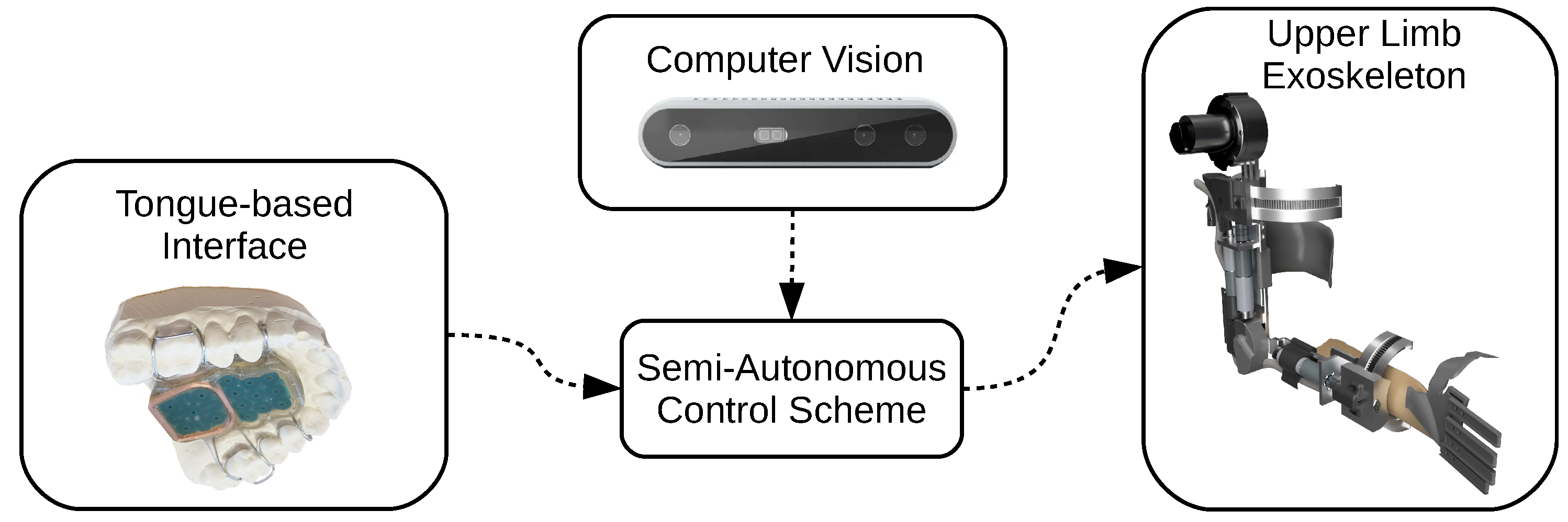
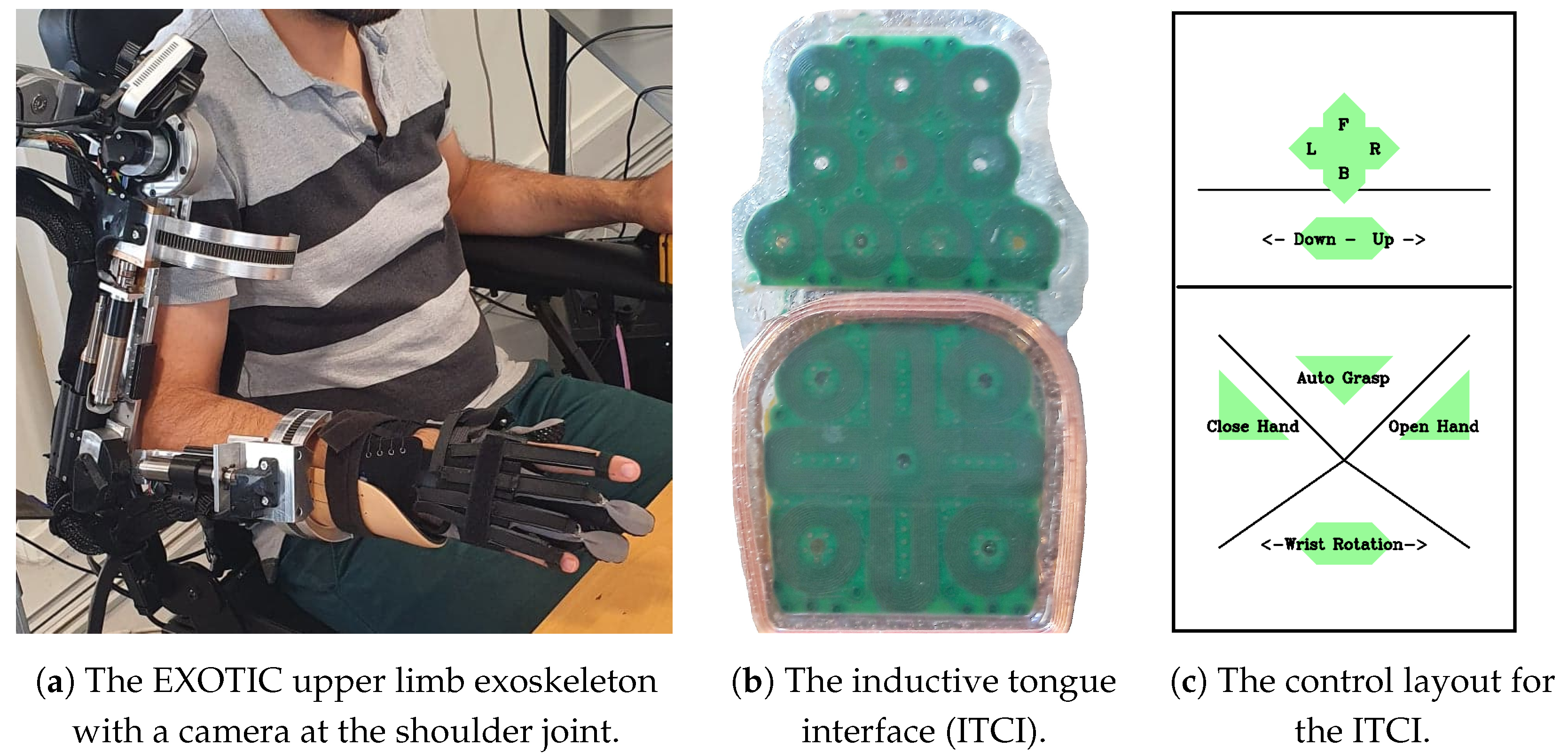
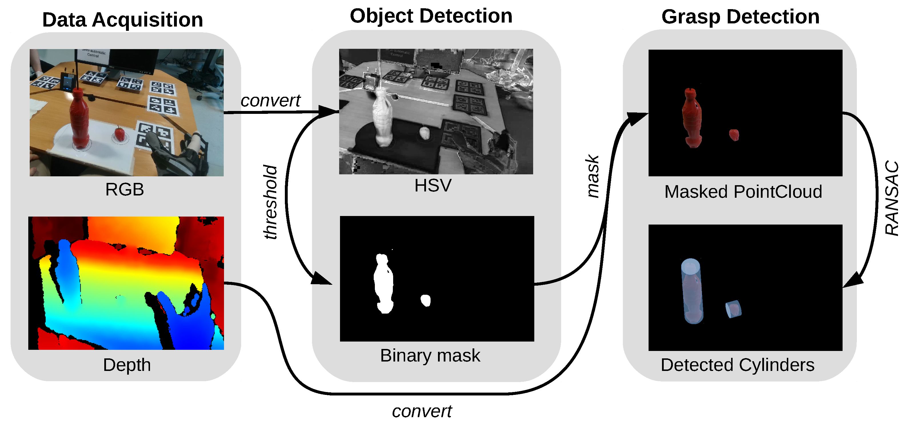
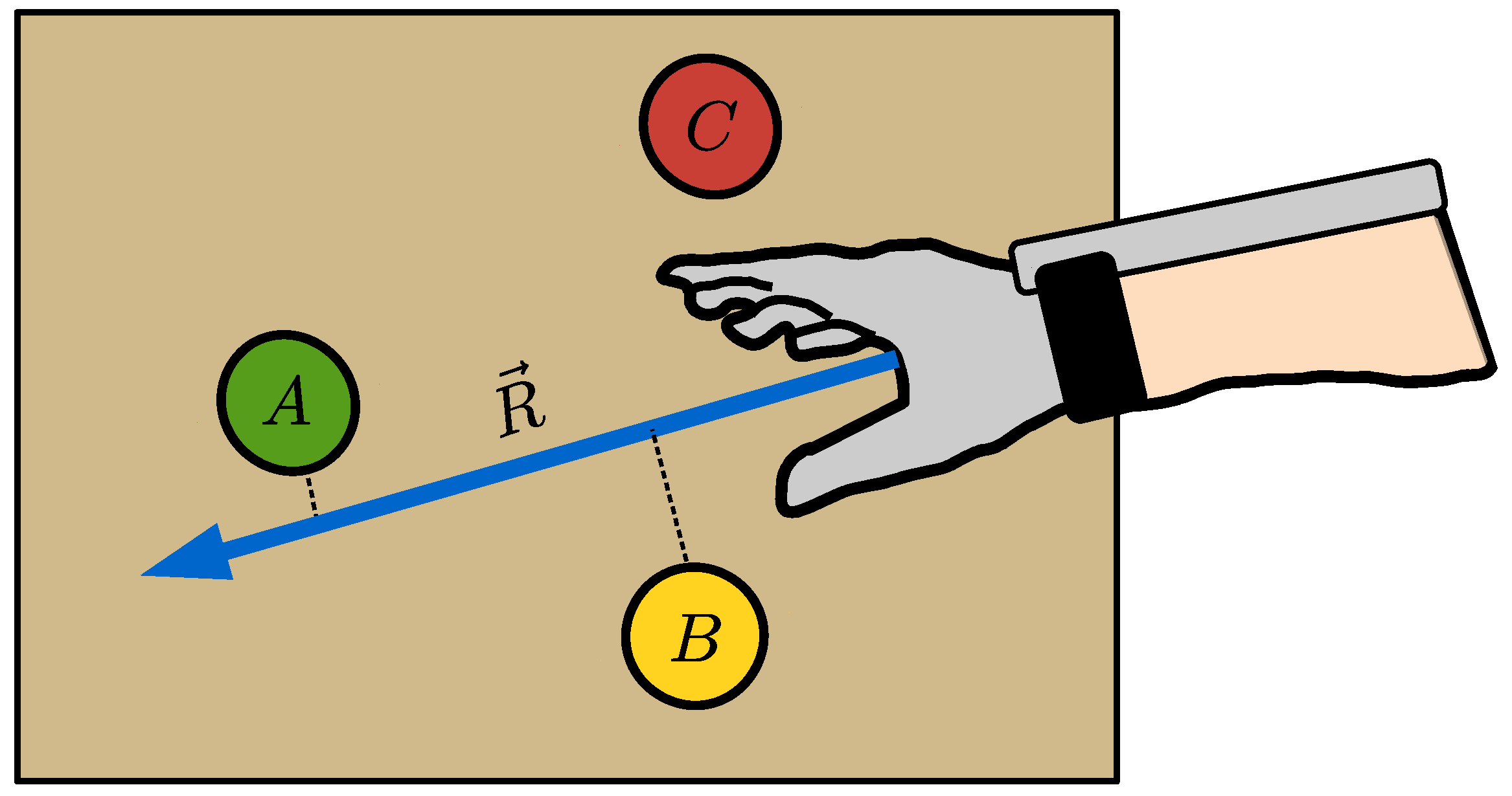
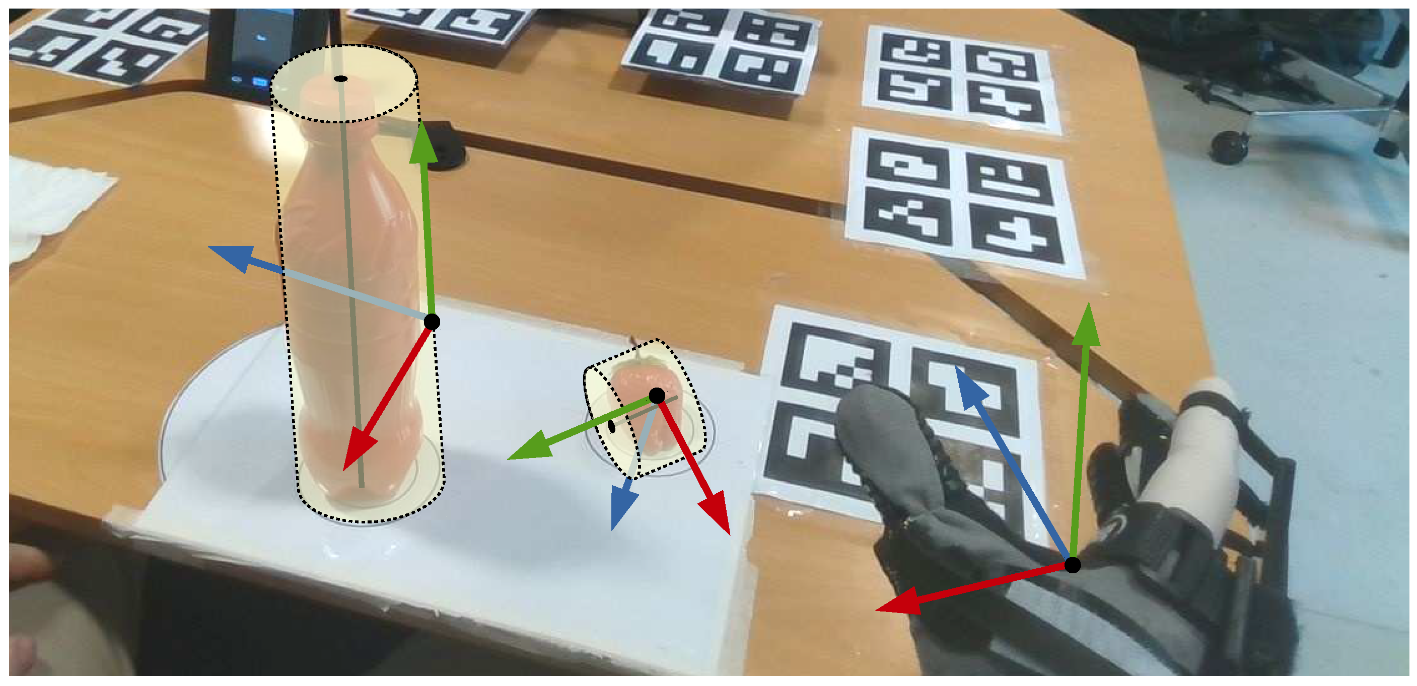
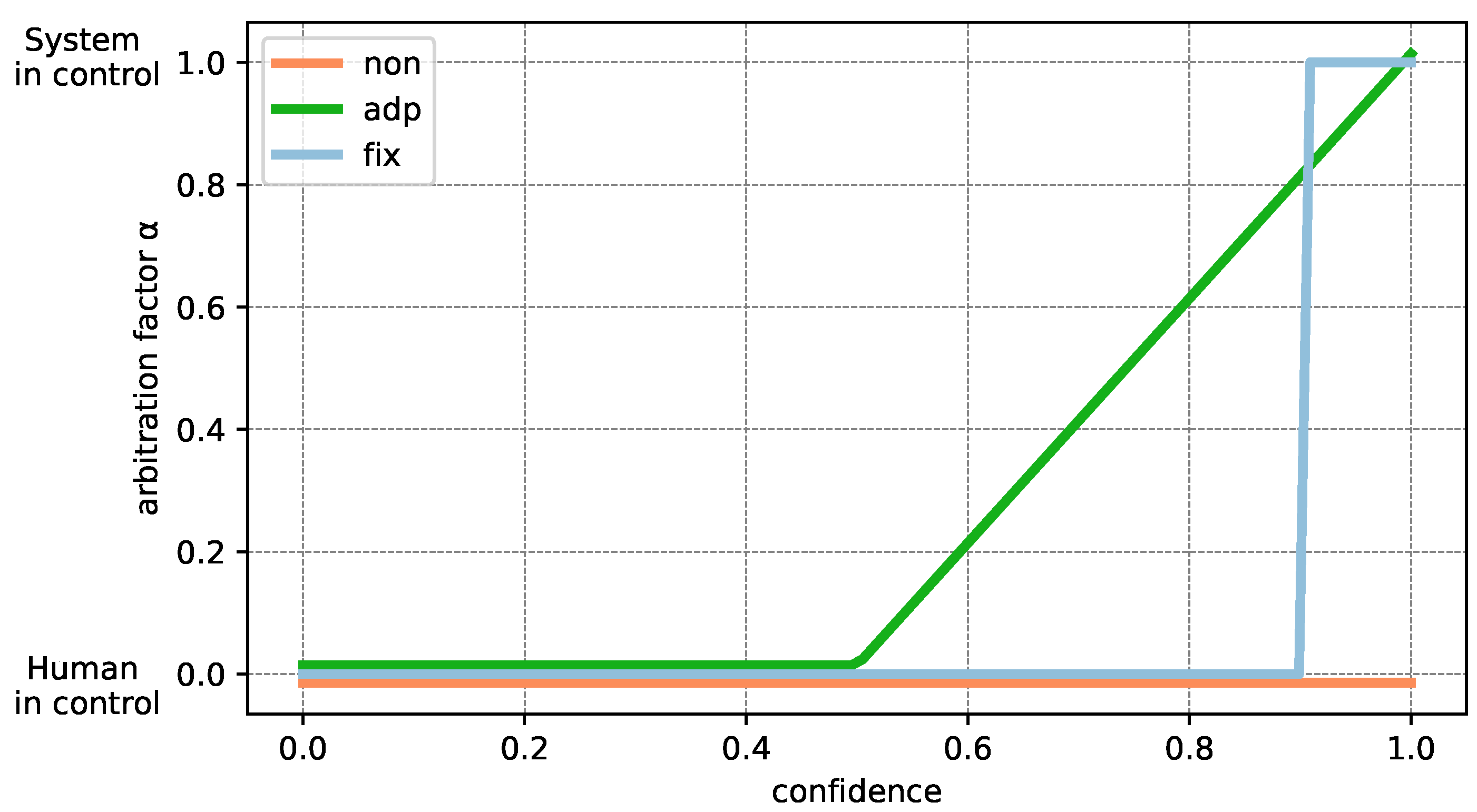
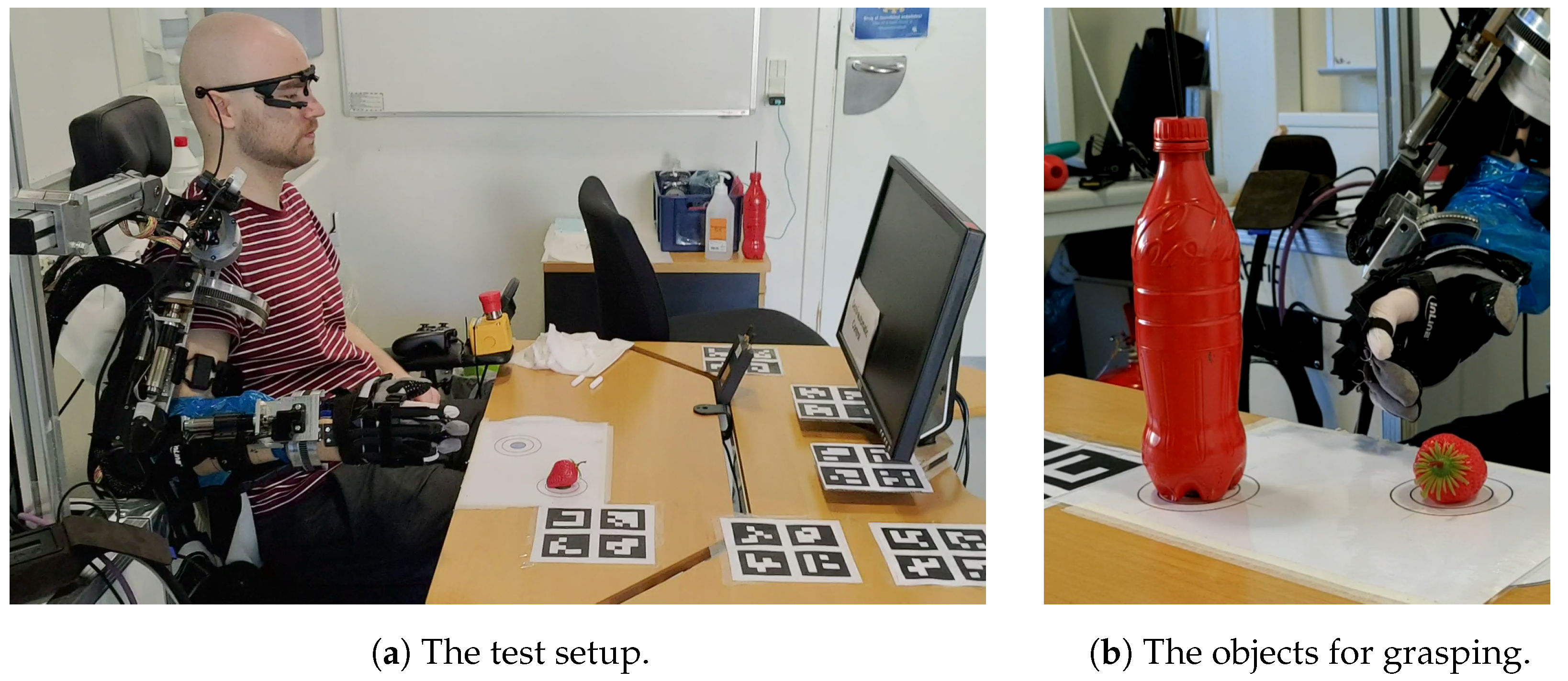
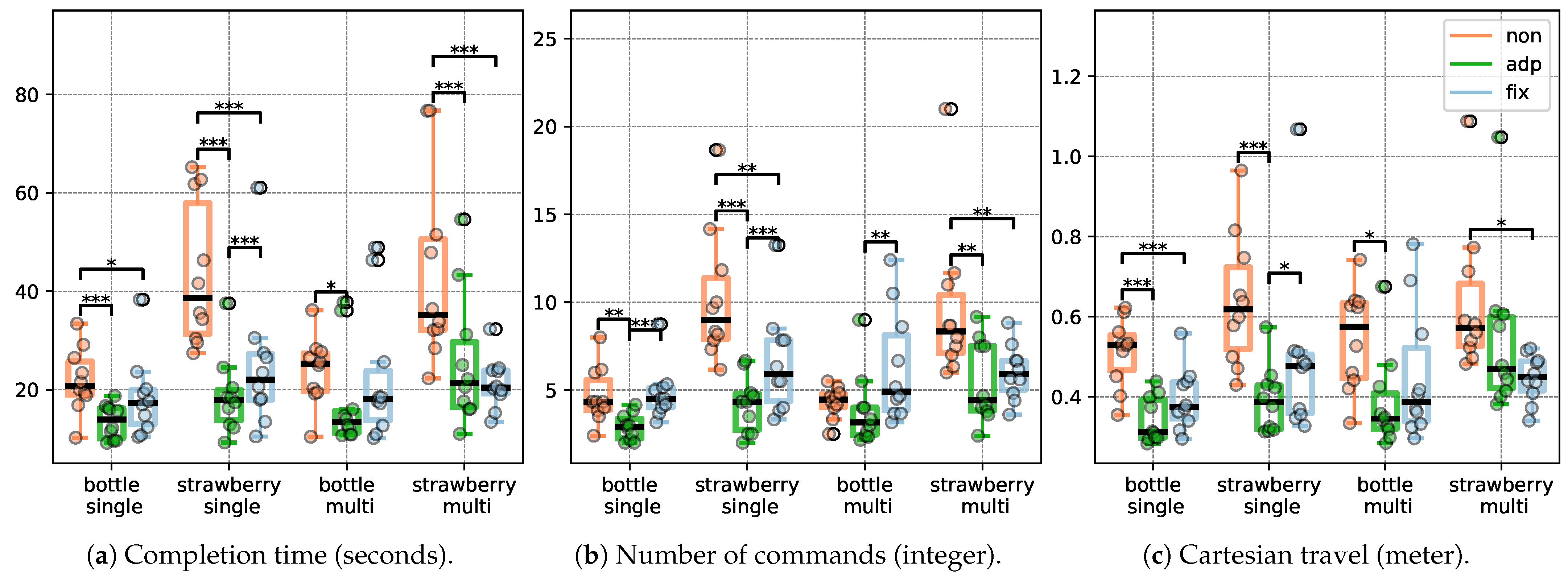

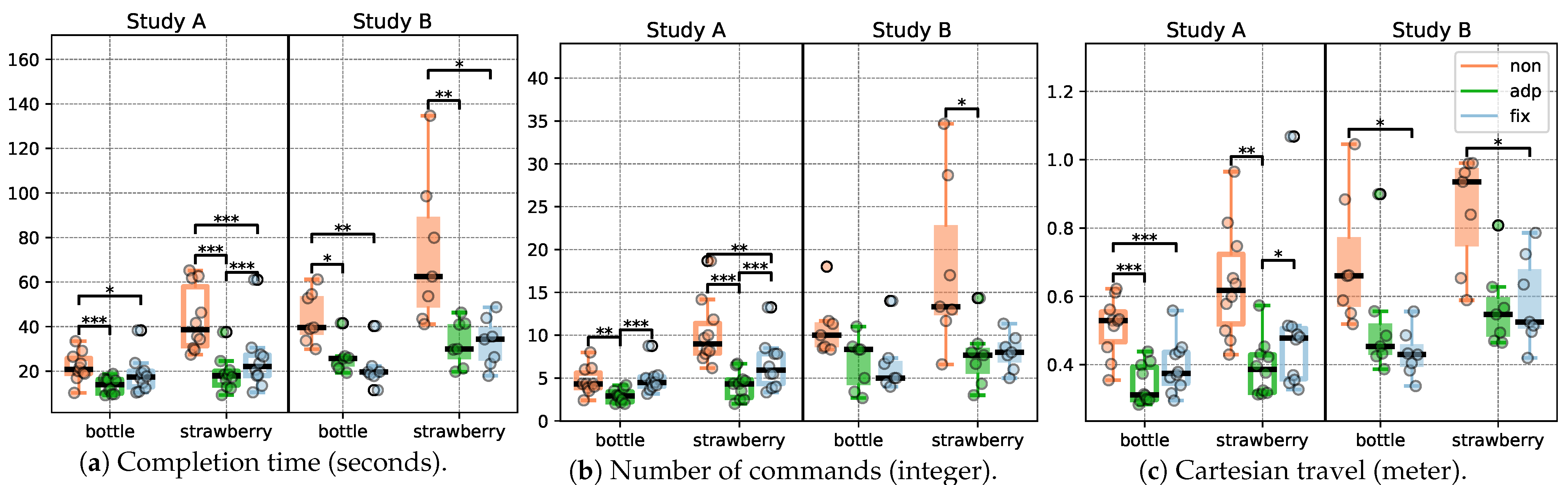
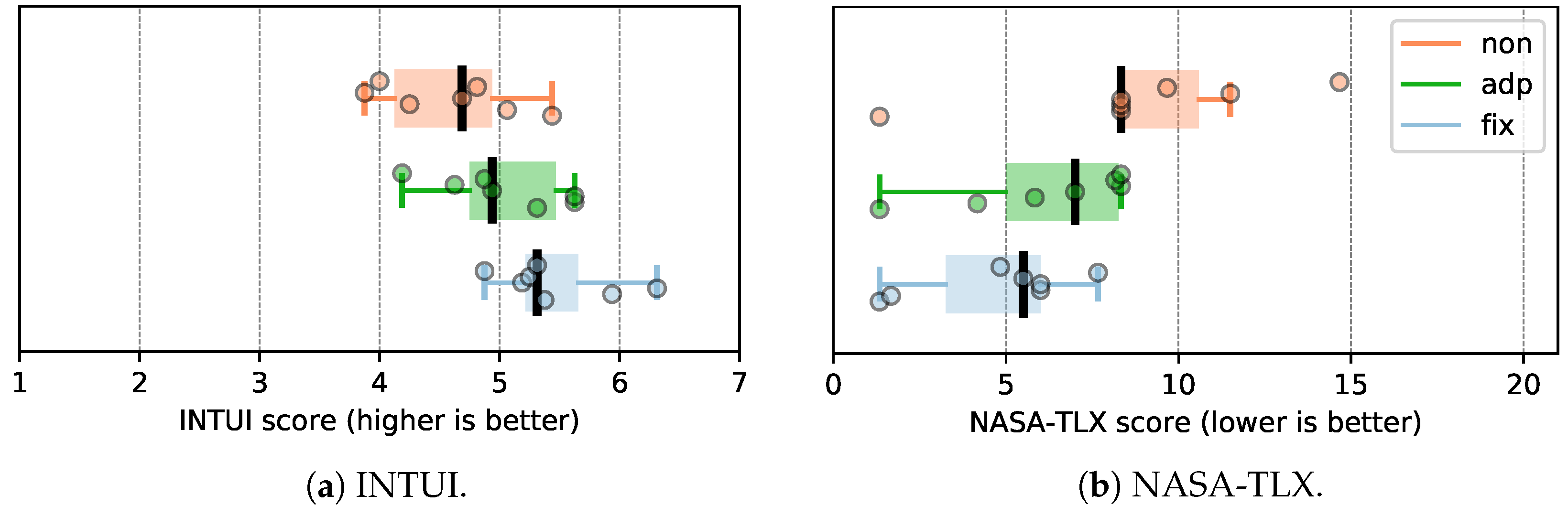

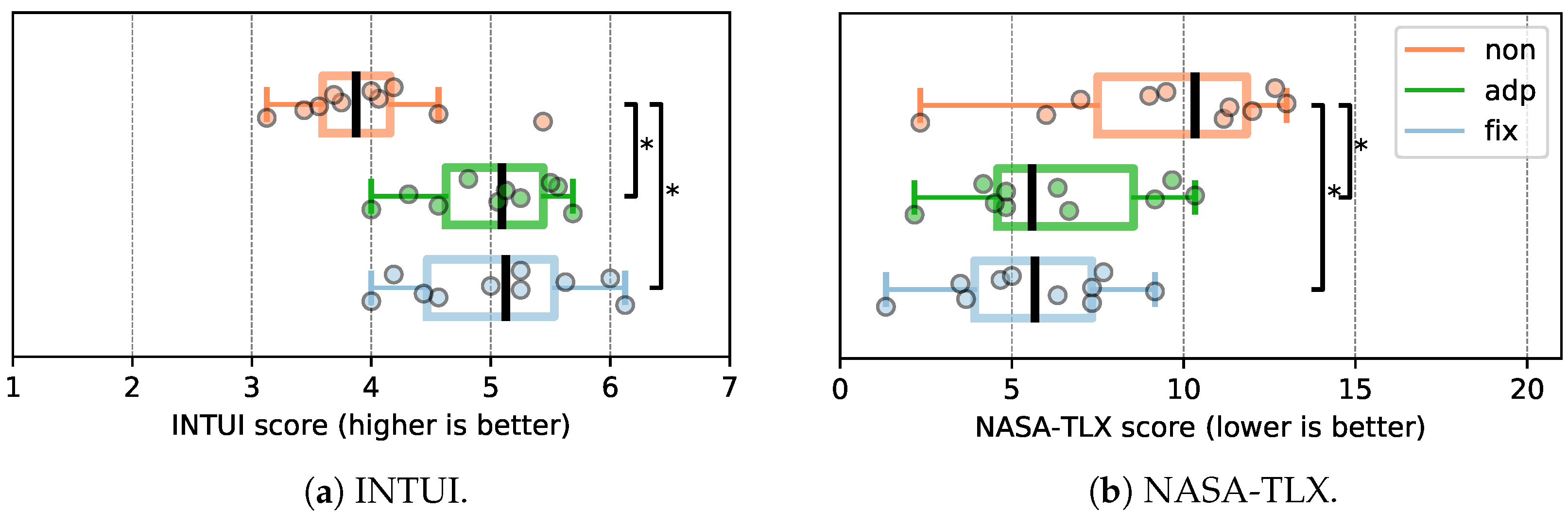